Abstract
A fastener for use with undergarment, including a first tape having a body provided with a plurality of first connectors; a second tape having a body provided with a plurality of second connectors for connecting with the first connectors in the first tape; and each of the first and second tapes includes an attachment portion having a retainer adapted for connecting with the undergarment, the first and second connectors are elastic; and a method of forming the same.
Claims (20)
1. A fastener for use with undergarment, comprising: a first tape having a body provided with a plurality of first connectors; a second tape having a body provided with a plurality of second connectors for connecting with the first connectors in the first tape; and each of the first and second tapes includes an attachment portion having a retainer adapted for connecting with said undergarment; wherein the first and second connectors are self restorable; wherein the attachment portion of each of the first and second tapes is provided at a first end of each of the first and second tapes; and the retainer of the attachment portion comprises a space defined by upper and lower layers of the attachment portion, the space is configured to receive a part of said undergarment.
18. A fastener for use with undergarment, comprising: a first tape having a body provided with a plurality of first connectors; a second tape having a body provided with a plurality of second connectors for connecting with the first connectors in the first tape; and each of the first and second tapes includes an attachment portion having a retainer adapted for connecting with said undergarment; wherein the first and second connectors are self-restorable; wherein the attachment portion of each of the first and second tapes includes a lamination of two layers of materials with different stretchabilities.
19. A fastener for use with undergarment, comprising: a first tape having a body provided with a plurality of first connectors; a second tape having a body provided with a plurality of second connectors for connecting with the first connectors in the first tape; and each of the first and second tapes includes an attachment portion having a retainer adapted for connecting with said undergarment; wherein the first and second connectors are self-restorable; wherein the plurality of first connectors are provided adjacent the attachment portion; the first tape includes a gripper portion provided opposite to the attachment portion of the first tape for manipulating by fingers of a user; and the gripping portion is devoid of the plurality of first connectors.
20. A fastener for use with undergarment, comprising: a first tape having a body provided with a plurality of first connectors; a second tape having a body provided with a plurality of second connectors for connecting with the first connectors in the first tape; and each of the first and second tapes includes an attachment portion having a retainer adapted for connecting with said undergarment; wherein the first and second connectors are self-restorable; wherein the attachment portion is provided at a first end of each of the first and second tapes; wherein the plurality of first connectors are supported on a backing sheet; and the attachment portion of the first tape is sewn onto said backing sheet and a base layer.
Show 16 dependent claims
2. The fastener as claimed in claim 1 , wherein the plurality of first connectors is provided adjacent the attachment portion of the first tape.
3. The fastener as claimed in claim 2 , wherein the plurality of first connectors and the attachment portion of the first tape are in connection with a base layer.
4. The fastener as claimed in claim 3 , wherein the base layer is formed from a layer of stretchable material.
5. The fastener as claimed in claim 3 , wherein the base layer is movable from a first position in which the first plurality of connectors is concealed, to a second position in which the first plurality of connectors is exposed.
6. The fastener as claimed in claim 3 , wherein the base layer is attached to the plurality of first connectors by way of adhesive.
7. The fastener as claimed in claim 3 , wherein the base layer is fixed to the plurality of first connectors via a support layer.
8. The fastener as claimed in claim 2 , wherein the first tape includes a gripper portion provided opposite to the attachment portion of the first tape for manipulating by fingers of a user.
9. The fastener as claimed in claim 8 , wherein the gripping portion is devoid of the first connectors.
10. The fastener as claimed in claim 9 , wherein at least a part of the gripping portion includes a layer of stretchable material.
11. The fastener as claimed in claim 1 , wherein the attachment portion of each of the first and second tapes includes a lamination of two layers of materials with different stretchabilities.
12. The fastener as claimed in claim 1 , wherein the plurality of first connectors is supported on a backing sheet.
13. The fastener as claimed in claim 12 , wherein the attachment portion of the first tape is sewed onto said backing sheet and a base layer.
14. The fastener as claimed in claim 1 , wherein the plurality of first connectors comprise self restorable hook connectors and the plurality of second connectors comprise self restorable loop connectors for engaging the hook connectors.
15. A method of manufacturing a first tape as claimed in claim 1 comprising the steps of: providing a layer of first self restorable connectors; attaching the layer of first self restorable connectors onto a support layer; attaching a base layer to at least one of the layer of first self restorable connectors and the support layer at three sides of the base layer; moving the base layer from a first position to a second position to simultaneously expose the layer of first self restorable connectors, place the base layer under the support layer and conceal the three sides at which the base layer is attached to the layer of first self restorable connectors and the support layer.
16. The method as claimed in claim 15 further comprising the step of forming a gripping portion adjacent the layer of first self restorable connectors.
17. The fastener as claimed in claim 1 , wherein the first and second tapes are hook and loop tapes.
Full Description
Show full text →
The present invention relates to a fastener for use with clothing to close off openings, for example particularly, but not exclusively, a hook and eye fastener for undergarment.
BACKGROUND OF THE INVENTION
Conventional hook and eye fastener is a type of closure commonly used in clothing and sewing projects. It consists of two separate pieces: a small hook and a small eye. The hook is typically sewn onto one side of a garment or piece of fabric while the eye is sewn onto another side. The hook is then inserted into the eye to create a secure closure. This type of fastener is often used on the back of dresses, skirts, and blouses. It is a simple and effective alternative to close a garment other than buttons or zippers.
With the eye connector lying flat on the upper surface of an eye tape, it can be difficult for user to insert the hook connector sewed to the hook tape, especially when it is done without looking. It is relatively common to use at least two pairs of hook and eye fasteners to securely close off an opening. It can be difficult to fastener one pair of hook and eye fastener blind folded, not to mention two.
The problem is more profound with the less able such as an elderly who has weak grip and shaky hands. The challenges in using hook and eye fasteners are shared by the disabled and young children.
Hook and eye connectors are usually made from wire or plastic. These materials are relatively hard and may cause discomfort to the skin of a user. This is particularly the case when they are used with undergarments. Cushions have been applied to mask the hardness of the hook and eye connectors from the skin of a user but the fastener becomes very bulky. The bulkiness affects the aesthetic appearance of the undergarment and makes it difficult to conceal.
The invention seeks to eliminate or at least to mitigate such shortcomings by providing a fastener for use with garments.
SUMMARY OF THE INVENTION
In a first aspect of the invention there is provided a fastener for use with undergarment, comprising a first tape having a body provided with a plurality of first connectors; a second tape having a body provided with a plurality of second connectors for connecting with the first connectors in the first tape; and each of the first and second tapes includes an attachment portion having a retainer adapted for connecting with said undergarment; wherein the first and second connectors are self restorable; preferably, the attachment portion is provided at a first end of the tape; more preferably, the retainer of the attachment portion comprises a space defined by upper and lower layers of the attachment portion, the space is configured to receive a part of said undergarment; yet more preferably, the first connectors are provided adjacent the attachment portion. It is preferable that the first connectors and the attachment portion are in connection with a base layer; advantageously, the base layer is formed from a layer of stretchable material; more advantageously, the attachment portion includes a lamination of two layers of materials with different stretchabilities. Yet more advantageously, the first tape includes a gripper portion provided opposite to the attachment portion for manipulating by fingers of a user. In a preferred embodiment, the gripping portion is devoid of the first connectors; preferably, at least a part of the gripping portion includes a layer of stretchable material; preferably, the base layer is movable from a first position in which the first connectors connectors are concealed, to a second position in which the first connectors are exposed; more preferably, the base layer is fixed in position by way of adhesive; it is preferable that the base layer is fixed to the first connection via a support layer; preferably, the first connectors are supported on a backing sheet; more preferably, the attachment portion is sewed onto a backing sheet and the base layer. It is preferable that the first connector comprises self restorable hook connector and the second connector comprises self restorable loop connector for engaging the hook connector. Preferably, the first and second tapes are Velcro™ tapes.
In a second aspect of the invention there is provided a method of manufacturing a first tape as claimed in claim 1 comprising the steps of:
•
• providing a layer of first self restorable connectors; • attaching the layer of first self restorable connectors onto a support layer; • attaching a base layer to at least one of the layer of first self restorable connectors and the support layer at three sides of the base layer; • moving the base layer from a first position to a second position to simultaneously expose the layer of first self restorable connectors, place the base layer under the support layer and conceal the three sides at which the base layer is attached to the layer of first self restorable connectors and the support layer; preferably, the method further comprises the step of forming a gripping portion adjacent the layer of first self restorable connectors.
BRIEF DESCRIPTION OF DRAWINGS
The invention will now be more particularly described, by way of example only, with reference to the accompanying drawings, in which:
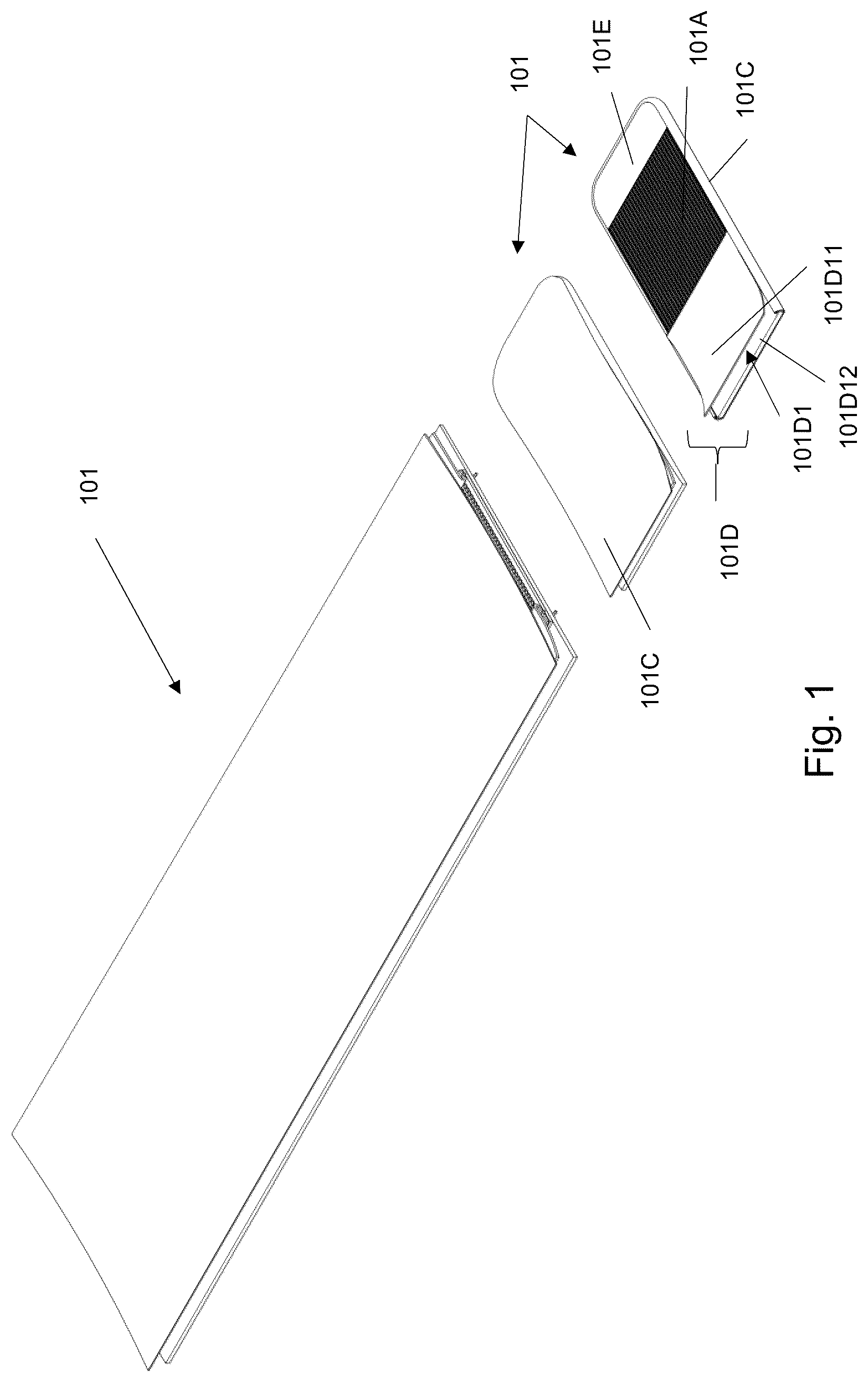
is an illustrative perspective view of the formation of a hook tape of a first embodiment of a fastener in accordance with the invention;
A is an illustrative cross-sectional view of the hook tape in at a first state;
B is an illustrative cross-sectional view of the hook tape in at a second state;
A is a perspective view of the hook tape in B ;
B is a side view of the hook tape in B ;
is an illustrative perspective view of the formation of a loop tape of the first embodiment of the fastener in accordance with the invention;
A is an illustrative cross-sectional view of the loop tape in at the first state;
B is an illustrative cross-sectional view of the loop tape in at its second state;
A and 6 B are illustrative perspective views of the loop tape in ;
C is an illustrative side view of the loop tape in ;
A is an illustrative perspective view showing the hook and loop tapes of the first embodiment of the fastener being fastened;
B is an illustrative perspective view showing the fastener in A with a gripping portion being raised;
is an illustrative perspective view of the formation of a hook tape of the second embodiment of the fastener in accordance with the invention;
A is an illustrative cross-sectional view of the hook tape in ;
B is an illustrative perspective view of the hook tape in ;
C is an illustrative side view of the hook tape in ;
is an illustrative perspective view of the formation of a loop tape of the second embodiment of the fastener in accordance with the invention;
A is an illustrative cross-sectional view of the loop tape in ;
B is an illustrative perspective view of the loop tape in ;
C is an illustrative side view of the loop tape in ;
A is an illustrative perspective view showing the hook and loop tapes of the second embodiment of the fastener being fastened; and
B is an illustrative perspective view showing the fastener in A with a gripping portion raised;
DETAILED DESCRIPTION OF PREFERRED EMBODIMENT
Referring to to 12 B , there is shown two embodiments of a fastener 100 and 200 in accordance with the invention. The fastener 100 or 200 may be used with and undergarment to close off openings. More specifically, it is used with a brasserie.
The fastener 100 or 200 includes a first, hook tape 101 / 201 , and a second, loop tape 102 / 202 , that are reversibly interconnectable. When used with a brasserie, the hook tape 101 / 201 is attached, for example by way of a seam, to one arm of the brasserie and the loop tape 102 / 202 is attached, for example by way of a seam, to another arm of the brasserie. Another possible way of attaching the hook and loop tapes 101 / 102 / 201 / 202 to respective arms of the brasserie may involve adhesive or ultrasonic welding. When fastened, hook and loop connectors 101 A/ 201 A/ 102 A/ 202 A on the hook and loop tapes 101 / 102 / 201 / 202 connect the arms of the brasserie to form a complete loop.
The hook tape 101 / 201 of both of the first and second embodiments includes a plurality of hook connectors 101 A/ 201 A extending from a backing sheet 101 B/ 201 B, which collectively forms a layer of hook connectors. The backing sheet 101 B/ 201 B are supported on a base layer 101 C/ 201 C. More specifically the layer of hook connectors is attached, directly or indirectly and possibly by way of adhesive, to the base layer 101 C/ 201 C for support. An attachment portion 101 D/ 201 D is provided at one end of the hook tape 101 / 201 and adjacent the hook connectors 101 A/ 201 A. A gripping portion 101 E/ 201 E is provided at another end of the hook tape 101 / 201 and located opposite to the attachment portion 101 D/ 201 D. The gripping proton 101 E/ 201 E and the attachment portion 101 D/ 201 D are devoid of any hook connectors 101 A/ 201 A. A window is defined between the gripping portion 101 E/ 201 E and the attachment portion 101 D/ 201 D through which the hook connectors 101 A/ 201 A are exposed. The attachment portion 101 D/ 201 D includes a retainer 101 D 1 / 201 D 1 which is an opened end dimensioned to receive the arm of a brasserie.
The loop tape 102 / 202 of both of the first and second embodiments include a plurality of loop connectors 102 A/ 202 A extending from a backing sheet 102 B/ 202 B, which collectively forms a layer of loop connectors. The layer of loop connectors are supported on a base layer 102 C/ 202 C. More specifically the layer of loop connectors is attached, directly or indirectly and possibly by way of adhesive, to the base layer 102 C/ 202 C for support. An attachment portion 102 D/ 202 D is provided at one end of the loop tape 102 / 202 and adjacent the loop connectors 102 A/ 202 A. The attachment portion 102 D/ 202 D is devoid of any loop connectors 102 A/ 202 A.
The hook connectors 101 A/ 201 A and the loop connectors 102 A/ 202 A are made of pliable, elastic and/or self-restorable material. An example would be a Velcro™ hook and loop connectors.
With reference to A and 7 B as well as A and 12 B , the hook tape 101 / 201 is placed on top of the loop tape 102 / 202 and the two are pressed against one another so as to allow the hook connectors 101 A/ 201 A on the hook tape 101 / 201 to engage, by way of hooking, onto the loop connectors 102 A/ 202 A of the loop tape 102 / 202 . Overlapping between the hook tape 101 / 201 and the loop tape 102 / 202 is adjustable lengthwise so as to adjust the overall length of the fastener 100 / 200 , hence the overall length of the connected arms of the brasserie. The greater the degree of the lengthwise overlapping between the hook and loop tapes 101 / 201 / 102 / 202 , the shorter the overall length of the fastener 100 / 200 .
to 3 B show a hook tape 101 of the first embodiment of the fastener.
Referring to , there is shown an elongated tape that is cut into hook tapes 101 of preferred dimension. As can be seen from the , the hook connectors 101 A are concealed by a base layer 101 C which has three sides attached to corresponding three sides of the support layer 101 G/backing sheet 101 B to form a pocket with an opened end. Through the opened end, the base layer 101 C is moved or flipped to simultaneously reveal the hook connectors 101 A and be placed underneath the support layer 101 G.
In more detail, as shown in A to 3 B , the backing sheet 101 B is placed over a support layer 101 G and occupies the middle portion of the support layer 101 G. One end of the hook tape 101 is provided with a gripping portion 101 E. The gripping portion 101 E is made of stretchable or elastic material and it is devoid of hook connectors 101 A. The gripping portion 101 E is fixed in position by attaching to an upper surface of the backing sheet 101 B at one end portion and an upper surface of the support layer 101 G at another end portion. Such attachment may be by way of a seam or adhesive. In this specific embodiment, one end of the gripping portion 101 E is sewed onto the backing sheet 101 B and the support layer 101 G while the other end of the gripping portion 101 E is ultrasonically welded to the upper surface of the support layer 101 G which is not covered by the backing sheet 101 B. The attachment portion 101 D is provided at another end of the hook tape 101 opposite the gripping portion 101 E, thereby defines a window through which the hook connectors 101 A are exposed. The attachment portion 101 D includes a retainer 101 D 1 defined by a gap between a folded layer of fabric 101 D 11 and a corresponding end portion 101 D 12 of the support layer 101 G which is not covered by the backing sheet 101 B. The fabric 101 D 11 is a lamination of two layers of fabric with different stretchabilities. A first layer being elastic and stretchable and a second layer being rigid and inelastic to offer support. This fabric 101 D 11 along with the end portion 101 D 12 of the support layer 101 G forms a retainer 101 D 1 in the form of an opened end dimensioned to receive an arm of a brasserie. The fabric 101 D 11 is sewed onto the backing sheet 101 B and the support layer 101 G.
In A , the base layer 101 C is placed above and covers the attachment portion 101 D, the gripping portion 101 E and the hook connectors 101 A. The base layer 101 C is attached to the three sides of the layers underneath it to form a pocket. By flipping the base layer 101 C inside out, simultaneously, the base layer 101 C is placed under the support layer 101 G whilst the hook connectors 101 A, the gripping portion 101 E and the attachment portion 101 D are revealed. At the same time, the three edges where the base layer 101 C is attached to the rest of the hook tape 101 are concealed as shown in B to 3 B . The base layer 101 C may be attached to the support layer 101 G in a further step by way of adhesive.
Referring to to 6 C , there is shown a first embodiment of the loop tape 102 .
In , there is shown an elongated tape that is cut into loop tapes 102 of preferred dimension. As can be seen from the A , the loop connectors 102 A are concealed by a base layer 102 C with three sides attached to corresponding three sides of the rest of the fastener 100 to form a pocket with an opened end. Through the opened end, the base layer 102 C is moved or flipped to reveal the loop connectors 102 A and being placed underneath the support layer 102 G simultaneously.
In more detail, as shown in to 6 C , the loop connectors 102 A and its backing sheet 102 B is placed over a support layer 102 G and occupies most of an upper surface of the support layer 102 G except an end portion where the attachment portion 102 D is provided. The attachment portion 102 D includes a retainer 102 D 1 defined by a folded layer of fabric 102 D 11 and a corresponding end portion 102 D 12 of the support layer 102 G. The fabric 102 D 11 is a lamination of two layers of fabric with different stretchabilities. An upper layer being elastic and stretchable and a lower layer being rigid and inelastic to offer support. This fabric 102 D 11 along with the end portion 102 D 12 of the support layer 102 G forms the retainer 102 D in the form of an opened end dimensioned to receive an arm of a brasserie. One end of the fabric 102 D 11 is sewed onto the backing sheet 102 B and the support layer 102 G.
In A to 6 C , the base layer 102 C is placed above and covers the attachment portion 102 D and the loop connectors 102 A. The base layer 102 C is attached to the three sides of the layers underneath it, which includes the backing sheet 102 B and the support layer 102 G to form a pocket. By flipping the base layer 102 C inside out, the base layer 102 C is placed under the support layer 102 G, the loop connectors 102 A and the attachment portion 102 D are revealed simultaneously while three edges at which the base layer 102 C is attached to the rest of the loop tape 102 are concealed by the base layer 102 C. The base layer 102 C may be attached to the support layer 102 G in a further step by way of adhesive as shown.
With reference to A and 7 B , the gripping portion 101 E offers a non-fastening portion that is devoid of any hook connectors 101 A. The gripping portion 101 E permits easy disconnection of the hook tape 101 from the loop tape 102 by offering a part to be held by fingers of a user for pulling the hook tape 101 from the hook tape 101 after the two are fastened. It also makes it easy to bring the hook tape 101 and the loop tape 102 together. In another embodiment, the gripping portion may be provided with the loop tape 102 .
to 12 B show a second embodiment of the fastener in accordance with the invention. The construction of the hook and loop tapes 201 / 202 in the second embodiment of the fastener is slightly different from that in the first embodiment as an adaptation for suiting different needs.
Referring to , there is shown an elongated tape that is cut into hook tapes 201 of preferred dimension. As can be seen from the , the hook tape 201 is a lamination of various layers of material including a layer of hook connectors 201 A supported by a backing sheet 201 B which is positioned above a base layer 201 C. The backing sheet 201 B and the base layer 201 C are attached to one another via a layer of heat sensitive adhesive material 201 H.
In more detail, as shown in A to 9 C , the hook connectors 201 A occupy a middle portion of backing sheet 201 B and the overall hook tape 201 . The backing sheet 201 B is of the same dimension as the base layer 201 C for supporting a gripping portion 201 E at one end and an attachment portion 201 D at another end opposite that of the first mentioned end. The gripping portion 201 E is a lamination of two layers of fabric with different strechabilities. A first layer of the fabric is a stretchable or elastic material supported by a second layer that is relatively more rigid and inelastic. The gripping portion 201 E is devoid of hook connectors 201 A and is fixed in position by adhesively attached to the backing sheet 201 B. The attachment portion 201 D and the gripping portion 201 E define a window through which the hook connectors 201 A are exposed. The attachment portion 201 D includes a retainer 201 D 1 defined by a folded layer of fabric. The fabric 201 D 11 is a lamination of two layers of fabric with different stretchabilities. First layer is elastic and stretchable and a second layer being rigid and inelastic to offer support. The folded layer forms an opened end dimensioned to receive an arm of a brasserie. Lower portion of the folded layer is attached to the backing layer 201 B by adhesive while the upper layer forms an upper surface of the fastener 200 along with the hook connectors 201 A and the gripping portion 201 E.
Referring to to 11 C , there is shown a loop tape 202 of a second embodiment of the fastener 200 . As can be seen from the figures, the loop tape 202 is a lamination of various layers of material including a layer of loop connectors 202 A placed on top of a backing sheet 202 B which is positioned above a base layer 202 C. The backing sheet 202 B and the base layer 202 C are attached to one another by way of a layer of heat sensitive adhesive 202 H.
In , there is shown an elongated tape that is cut into loop tapes 202 of preferred dimension. The backing sheet 202 B along with the attachment portion 202 D occupied the entire upper surface of the base layer 202 C. The attachment portion 202 D includes a retainer 202 D 1 defined by a folded layer of fabric 202 D 11 . The fabric 202 D 11 is a lamination of two layers of fabric with different stretchabilities. First layer is elastic and stretchable and second layer is relatively rigid and inelastic to offer support. The folded layer forms an opened end dimensioned to receive an arm of a brasserie. Lower part of the folded layer is attached to the base layer 202 C by adhesive while the upper layer forms an upper surface of the fastener which is devoid of any loop connectors 202 A. The loop connectors 202 A and the upper layer of the attachment portion 202 D forms an upper surface of the fastener 202 .
With reference to A and 12 B , the gripping portion 201 E of the hook tape 201 offers a gripping portion that is devoid of any hook connectors 201 A. The gripping portion 201 E permits easy disconnection of the hook tape 201 from the loop tape 202 by offering a part to be held by fingers of a user for pulling the hook tape 201 from the loop tape 202 after the two are fastened. It also makes it easy to bring the hook tape 201 and the loop tape 202 together. In another embodiment, the gripping portion may be provided with the loop tape 202 .
The invention has been given by way of example only, and various other modifications of and/or alterations to the described embodiment may be made by persons skilled in the art without departing from the scope of the invention as specified in the appended claims.
Figures (12)
Citations
This patent cites (9)
- US4033348
- US5926926
- US2002/0023321
- US2005/0027279
- US2005/0131372
- US2016/0058631
- US2016/0128877
- US2016/0128878
- US2022/0386746