Power Distribution Architecture with Series-connected Bus Converter
Abstract
Apparatus for power conversion are provided. One apparatus includes a power converter including an input circuit and an output circuit. The power converter is configured to receive power from a source for providing power at a DC source voltage V S . The power converter is adapted to convert power from the input circuit to the output circuit at a substantially fixed voltage transformation ratio K DC =V OUT /V IN at an output current, wherein V IN is an input voltage and V OUT is an output voltage. The input circuit and at least a portion of the output circuit are connected in series across the source, such that an absolute value of the input voltage V IN applied to the input circuit is approximately equal to the absolute value of the DC source voltage V S minus a number N times the absolute value of the output voltage V OUT , where N is at least 1.
Claims (95)
1. An apparatus, comprising: a bus converter circuit having a first terminal, a second terminal, and a common terminal and being configured to convert power in a direction, the direction being one of the following: (a) a first direction in which the first terminal and common terminal form an input for receiving input power at a first voltage, V1, and the second terminal and the common terminal form an output for delivering output power at a second voltage, V2, or (b) a second direction in which the second terminal and the common terminal form an input for receiving input power at the second voltage, V2, and the first terminal and the common terminal form an output for delivering output power at the first voltage, V1; wherein the input and output are galvanically connected; wherein over a range of input voltages the bus converter circuit uses an essentially fixed voltage transformation ratio, K, equal to the second voltage, V2 divided by the first voltage, V1, (K=V2/V1), to convert power in the direction, such that output power delivered in the first direction is at the second voltage, V2=K×V1, and output power delivered in the second direction is at the first voltage, V1=V2/K; wherein the first voltage, V1, is greater than the second voltage, V2; wherein the bus converter circuit includes (i) a transformer having a first winding and a second winding, (ii) a plurality of switches, and (iii) a controller configured to operate the plurality of switches in a series of converter operating cycles; wherein each converter operating cycle includes a first and a second power transfer interval, the first and second power transfer intervals having essentially equal durations, and wherein during the first power transfer interval a first set of the plurality of switches is ON and power is converted in the direction, and during the second power transfer interval a second set of the plurality of switches is ON and power is converted in the direction; wherein the bus converter circuit is configured during the first power transfer interval (a) to form a first series circuit in which at least the following elements are all connected in series without regard to order: at least one of the first or second terminals, at least one of the first or second windings of the transformer, at least one of the plurality of switches in the first set, and at least one capacitor, and (b) to conduct current in the direction between the first terminal and the second terminal; wherein the bus converter circuit is configured during the second power transfer interval (a) to form a second series circuit in which at least the following elements are all connected in series without regard to order: at least one of the first or second terminals, at least one of the first or second windings of the transformer, at least one of the plurality of switches in the second set, and at least one capacitor, and (b) to conduct current in the direction between the first terminal and the second terminal; wherein the bus converter circuit is configured to, before the first power transfer interval, reduce a voltage across a first ZVS switch prior to turning the first ZVS switch ON, such that the voltage across the first ZVS switch is reduced when the first ZVS switch is turned ON, the first ZVS switch being at least one of the plurality of switches in the first set; and wherein the bus converter circuit is configured to, before the second power transfer interval, reduce a voltage across a second ZVS switch prior to turning the second ZVS switch ON, such that the voltage across the second ZVS switch is reduced when the second ZVS switch is turned ON, the second ZVS switch being at least one of the plurality of switches in the second set.
68. A method, comprising: providing a bus converter circuit having a first terminal, a second terminal, and a common terminal and being configured to convert power in a direction, the direction being one of the following: (a) a first direction in which the first terminal and common terminal form an input for receiving input power at a first voltage, V1, and the second terminal and the common terminal form an output for delivering output power at a second voltage, V2, or (b) a second direction in which the second terminal and the common terminal form an input for receiving input power at the second voltage, V2, and the first terminal and the common terminal form an output for delivering output power at the first voltage, V1; galvanically connecting the input and the output; wherein over a range of input voltages the bus converter circuit a uses an essentially fixed voltage transformation ratio, K, equal to the second voltage, V2 divided by the first voltage, V1, (K=V2/V1), to convert power in the direction, such that output power delivered in the first direction is at the second voltage, V2=K×V1, and output power delivered in the second direction is at the first voltage, V1=V2/K; wherein the first voltage, V1, is greater than the second voltage, V2; wherein the bus converter circuit includes (i) a transformer having a first winding and a second winding, (ii) a plurality of switches, and (iii) a controller; operating, by the controller, the plurality of switches in a series of converter operating cycles including a first and a second power transfer interval, the first and second power transfer intervals having essentially equal durations, and wherein during the first power transfer interval a first set of the plurality of switches is ON and power is converted in the direction, and during the second power transfer interval a second set of the plurality of switches is ON and power is converted in the direction; forming, by the bus converter circuit, during the first power transfer interval a first series circuit in which at least the following elements are all connected in series without regard to order: at least one of the first or second terminals, at least one of the first or second windings of the transformer, at least one of the plurality of switches in the first set, and at least one capacitor, and conducting, by the bus converter circuit, current in the direction between the first terminal and the second terminal; forming, by the bus converter circuit, during the second power transfer interval a second series circuit in which at least the following elements are all connected in series without regard to order: at least one of the first and second terminals, at least one of the first or second windings of the transformer, at least one of the plurality of switches in the second set, and at least one capacitor, and conducting, by the bus converter circuit, current in the direction between the first terminal and the second terminal; before the first power transfer interval, reducing, by the bus converter circuit, a voltage across a first ZVS switch prior to turning the first ZVS switch ON, such that the voltage across the first ZVS switch is reduced when the first ZVS switch is turned ON, the first ZVS switch being at least one of the plurality of switches in the first set; and reducing, by the bus converter circuit, a voltage across a second ZVS switch prior to turning the second ZVS switch ON, such that the voltage across the second ZVS switch is reduced when the second ZVS switch is turned ON, the second ZVS switch being at least one of the plurality of switches in the second set.
85. A method of powering a computer processor, the method comprising: using an input bus to distribute input power at a first voltage, V1; using one or more non-isolated bus converters to convert power received from the input bus for delivery to an output at a second voltage, V2; using one or more output power busses to distribute power from the one or more bus converters at the second voltage, V2, to one or more loads; using a plurality of regulators to regulate power received from the output power busses for delivery via a regulator output to the one or more loads; and wherein one or more of the loads comprise a computer processor; wherein the one or more non-isolated bus converters have a first terminal, a second terminal, and a common terminal, and the first terminal and common terminal form an input connected to receive power from the input bus at the first voltage, V1, and the second terminal and the common terminal form an output for delivering output power at the second voltage, V2, to the one or more power busses; wherein the input is galvanically connected to the output; using an essentially fixed voltage transformation ratio, K, equal to the second voltage, V2 divided by the first voltage, V1, (K=V2/V1), to convert power in the one or more bus converters from the input for delivery to the output at the second voltage, V2=K×V1, over a range of input voltages; wherein the first voltage, V1, is greater than the second voltage, V2; wherein the one or more non-isolated bus converters include (i) a transformer having a first winding and a second winding, (ii) a plurality of switches, and (iii) a controller; using the controller to operate the plurality of switches in a series of converter operating cycles including a first and a second power transfer interval, the first and second power transfer intervals having essentially equal durations, and wherein during the first power transfer interval a first set of the plurality of switches is ON and power is converted from the input to the output, and during the second power transfer interval a second set of the plurality of switches is ON and power is converted from the input to the output; wherein the one or more non-isolated bus converters are configured, during the first power transfer interval to (a) form a first series circuit in which at least the following elements are all connected in series without regard to order: at least one of the first or second terminals, at least one of the first or second windings of the transformer, at least one of the plurality of switches in the first set, and at least one capacitor, and (b) convert current flowing through the first terminal into current flowing through the second terminal in inverse proportion to the essentially fixed voltage transformation ratio, K; wherein the one or more non-isolated bus converters are configured during the second power transfer interval to (a) form a second series circuit in which at least the following elements are all connected in series without regard to order: at least one of the first and second terminals, at least one of the first or second windings of the transformer, at least one of the plurality of switches in the second set, and at least one capacitor, and (b) convert current flowing through the first terminal into current flowing through the second terminal in inverse proportion to the essentially fixed voltage transformation ratio, K; wherein the one or more non-isolated bus converters are configured before the first power transfer interval, to reduce a voltage across a first ZVS switch prior to turning the first ZVS switch ON, such that the voltage across the first ZVS switch is reduced when the first ZVS switch is turned ON, the first ZVS switch being at least one of the plurality of switches in the first set; and wherein the one or more non-isolated bus converters are configured before the second power transfer interval, to reduce a voltage across a second ZVS switch prior to turning the second ZVS switch ON, such that the voltage across the second ZVS switch is reduced when the second ZVS switch is turned ON, the second ZVS switch being at least one of the plurality of switches in the second set.
89. A computer apparatus comprising: a power distribution system including an input bus for receiving power at a relatively high safe voltage, preferably approximately 48 Volts; one or more bus converter circuits connected to receive power from the input bus; one or more power busses connected to receive power from the one or more bus converter circuits; a plurality of regulators, each having an input connected to receive power from the one or more power busses and an output for delivering a regulated output; and one or more semiconductor processors connected to receive power from one or more of the regulators; wherein at least one of the one or more bus converter circuits has a first terminal, a second terminal, and a common terminal and is configured to convert power in a first direction in which the first terminal and common terminal form an input for receiving input power at a first voltage, V1, and the second terminal and the common terminal form an output for delivering output power at a second voltage, V2; wherein the input and output are galvanically connected; wherein over a range of input voltages the at least one of the one or more bus converter circuits uses an essentially fixed voltage transformation ratio, K, equal to the second voltage, V2 divided by the first voltage, V1, (K=V2/V1), to convert power in the first direction, such that output power delivered is at the second voltage, V2=K×V1; wherein the first voltage, V1, is greater than the second voltage, V2; wherein the at least one of the one or more bus converter circuits includes (i) a transformer having a first winding and a second winding, (ii) a plurality of switches, and (iii) a controller configured to operate the plurality of switches in a series of converter operating cycles; wherein each converter operating cycle includes a first and a second power transfer interval, the first and second power transfer intervals having essentially equal durations, and wherein during the first power transfer interval a first set of the plurality of switches is ON and power is converted in the first direction, and during the second power transfer interval a second set of the plurality of switches is ON and power is converted in the first direction; wherein the at least one of the one or more bus converter circuits is configured during the first power transfer interval to (a) form a first series circuit in which at least the following elements are all connected in series without regard to order: at least one of the first or second terminals, at least one of the first or second windings of the transformer, at least one of the plurality of switches in the first set, and at least one capacitor, and (b) convert in the first direction current flowing through the first terminal into current flowing through the second terminal in inverse proportion to the essentially fixed voltage transformation ratio, K; wherein the at least one of the one or more bus converter circuits is configured during the second power transfer interval to (a) form a second series circuit in which at least the following elements are all connected in series without regard to order: at least one of the first or second terminals, at least one of the first or second windings of the transformer, at least one of the plurality of switches in the second set, and at least one capacitor, and (b) convert in the first direction current flowing through the first terminal into current flowing through the second terminal in inverse proportion to the essentially fixed voltage transformation ratio, K; wherein the at least one of the one or more bus converter circuits is configured to, before the first power transfer interval, reduce a voltage across a first ZVS switch prior to turning the first ZVS switch ON, such that the voltage across the first ZVS switch is reduced when the first ZVS switch is turned ON, the first ZVS switch being at least one of the plurality of switches in the first set; and wherein the at least one of the one or more bus converter circuits is configured to, before the second power transfer interval, reduce a voltage across a second ZVS switch prior to turning the second ZVS switch ON, such that the voltage across the second ZVS switch is reduced when the second ZVS switch is turned ON, the second ZVS switch being at least one of the plurality of switches in the second set.
Show 91 dependent claims
2. The apparatus of claims 1 , wherein the bus converter circuit is a self-contained assembly adapted to be installed as a unit.
3. A computer apparatus, comprising: a power distribution system including an input bus for receiving power at a relatively high safe voltage, preferably approximately 48 Volts; one or more bus converter circuits of claim 1 , connected to receive power from the input bus; one or more power busses connected to receive power from the one or more bus converter circuits; a plurality of regulators, each having an input connected to receive power from the one or more power busses and an output for delivering a regulated output; and one or more semiconductor processors connected to receive power from one or more of the plurality of regulators.
4. The apparatus of claim 1 , wherein forming the first and second series circuits comprises at least two of the first and second terminals.
5. The apparatus of claim 4 , further comprising: a power distribution bus connected to distribute power from the output; and a plurality of voltage regulators, wherein each voltage regulator comprises a regulator input connected to the power distribution bus to receive power from the output and a regulator output connected to supply power to a respective load, the plurality of voltage regulators each being separated by a distance from the bus converter circuit.
6. The apparatus of claim 5 , wherein the direction is the first direction.
7. The apparatus of claim 6 , wherein the respective load comprises a computer processor.
8. A computer apparatus, comprising: a power distribution system including an input bus for receiving power at a relatively high safe voltage, preferably approximately 48 Volts; one or more bus converter circuits of claim 4 , connected to receive power from the input bus; one or more power busses connected to receive power from the one or more bus converter circuits; a plurality of regulators, each having an input connected to receive power from the one or more power busses and an output for delivering a regulated output; and one or more semiconductor processors connected to receive power from one or more of the plurality of regulators.
9. The apparatus of claim 4 , wherein the bus converter circuit is further capable of converting power in either of the first direction or the second direction and the direction is a function of conditions external to the bus converter circuit.
10. A computer apparatus, comprising: a power distribution system including an input bus for receiving power at a relatively high safe voltage, preferably approximately 48 Volts; one or more bus converter circuits of claim 9 , connected to receive power from the input bus; one or more power busses connected to receive power from the one or more bus converter circuits; a plurality of regulators, each having an input connected to receive power from the one or more power busses and an output for delivering a regulated output; and one or more semiconductor processors connected to receive power from one or more of the plurality of regulators.
11. The apparatus of claim 4 , wherein the first series circuit comprises one or more of the following: (a) at least one component that is not in the second series circuit, (b) at least one component that is in the second series circuit but is connected in an order that is different from in the second series circuit, or (c) at least one component that is in the second series circuit but is connected to carry a current that flows in a direction that is opposite from a current that the component carries in the second series circuit.
12. A computer apparatus, comprising: a power distribution system including an input bus for receiving power at a relatively high safe voltage, preferably approximately 48 Volts; one or more bus converter circuits of claim 11 , connected to receive power from the input bus; one or more power busses connected to receive power from the one or more bus converter circuits; a plurality of regulators, each having an input connected to receive power from the one or more power busses and an output for delivering a regulated output; and one or more semiconductor processors connected to receive power from one or more of the plurality of regulators.
13. The apparatus of claim 4 , wherein the first set of switches includes one or more switches that are not in the second set of switches.
14. The apparatus of claim 4 , wherein the first set of switches does not include any switches that are in the second set of switches.
15. The apparatus of claim 4 , wherein at least one winding of the first series circuit is different than at least one winding of the second series circuit.
16. The apparatus of claim 4 , wherein at least one winding of the first series circuit is the same as at least one winding of the second series circuit.
17. The apparatus of claim 16 , wherein the at least one winding is configured in the first series circuit to carry current in one direction and in the second series circuit to carry current in another direction opposite to the one direction.
18. The apparatus of claim 16 , wherein the first series circuit and the second series circuit each comprises at least two windings of the transformer.
19. The apparatus of claims 18 , wherein the bus converter circuit is a self-contained assembly adapted to be installed as a unit.
20. A computer apparatus, comprising: a power distribution system including an input bus for receiving power at a relatively high safe voltage, preferably approximately 48 Volts; one or more bus converter circuits of claim 18 , connected to receive power from the input bus; one or more power busses connected to receive power from the one or more bus converter circuits; a plurality of regulators, each having an input connected to receive power from the one or more power busses and an output for delivering a regulated output; and one or more semiconductor processors connected to receive power from one or more of the plurality of regulators.
21. The apparatus of claim 18 , wherein the at least two windings in the first and second series circuits each comprises the first winding and the second winding, and the first winding and the second winding are configured in the first series circuit to carry current in one direction and are configured in the second series circuit to carry current in another direction opposite to the one direction.
22. The apparatus of claim 21 , wherein the first and second windings are configured in a first order in the first series circuit and in a second different order in the second series circuit.
23. The apparatus of claim 22 , wherein the first and second windings are configured in the first series circuit for current to flow in the first direction and in the second series circuit for current to flow in the another direction.
24. The apparatus of claim 18 , wherein the first and second series circuits form a first and a second series resonant circuit, each having a characteristic resonant period; and the essentially equal duration of the first and second power transfer intervals is less than each characteristic resonant period.
25. The apparatus of claims 24 , wherein the bus converter circuit is a self-contained assembly adapted to be installed as a unit.
26. The apparatus of claim 18 , wherein the transformer comprises a third winding and the first and second series circuits each further comprises the third winding.
27. The apparatus of claim 26 , wherein the first, second, and third windings are configured in the first series circuit to carry current in one direction and in the second series circuit to carry current in another direction opposite to the one direction.
28. The apparatus of claim 26 , wherein the first set of switches includes one or more switches that are not in the second set of switches.
29. The apparatus of claim 26 , wherein the first set of switches does not include any switches that are in the second set of switches.
30. The apparatus of claim 16 , wherein the transformer comprises a third winding and the first series circuit and the second series circuit each comprises at least two windings of the transformer.
31. The apparatus of claims 30 , wherein the bus converter circuit is a self-contained assembly adapted to be installed as a unit.
32. A computer apparatus, comprising: a power distribution system including an input bus for receiving power at a relatively high safe voltage, preferably approximately 48 Volts; one or more bus converter circuits of claim 30 , connected to receive power from the input bus; one or more power busses connected to receive power from the one or more bus converter circuits; a plurality of regulators, each having an input connected to receive power from the one or more power busses and an output for delivering a regulated output; and one or more semiconductor processors connected to receive power from one or more of the plurality of regulators.
33. The apparatus of claim 4 , wherein the voltage across the first ZVS switch is reduced to nearly zero before the first ZVS switch is turned ON and the voltage across the second ZVS switch is reduced to nearly zero before the second ZVS switch is turned ON.
34. The apparatus of claim 1 , wherein the voltage across the first ZVS switch is reduced to nearly zero before the first ZVS switch is turned ON and the voltage across the second ZVS switch is reduced to nearly zero before the second ZVS switch is turned ON.
35. The apparatus of claim 1 , wherein at least one of the windings is coupled to the input and at least one of the windings is coupled to the output during the power transfer intervals.
36. The apparatus of claim 35 , wherein the first winding is coupled to the input during the first power transfer interval and the second winding is coupled to the output during the first power transfer interval.
37. The apparatus of claim 36 , wherein the transformer comprises a third winding and the third winding is coupled to the output during the second power transfer interval.
38. The apparatus of claim 1 , wherein the bus converter circuit is a self-contained assembly adapted to be installed as a unit.
39. The apparatus of claim 38 , wherein the direction is the first direction.
40. The apparatus of claim 6 , wherein the respective load comprises a computer processor.
41. The apparatus of claim 1 , wherein the first series circuit comprises one or more of the following: (a) at least one component that is not in the second series circuit, (b) at least one component that is in the second series circuit but is connected in an order that is different from in the second series circuit, or (c) at least one component that is in the second series circuit but is connected to carry a current that flows in a direction that is opposite from a current that the component carries in the second series circuit.
42. A computer apparatus, comprising: a power distribution system including an input bus for receiving power at a relatively high safe voltage, preferably approximately 48 Volts; one or more bus converter circuits of claim 41 , connected to receive power from the input bus; one or more power busses connected to receive power from the one or more bus converter circuits; a plurality of regulators, each having an input connected to receive power from the one or more power busses and an output for delivering a regulated output; and one or more semiconductor processors connected to receive power from one or more of the plurality of regulators.
43. The apparatus of claim 1 , wherein the first set of switches includes one or more switches that are not in the second set of switches.
44. The apparatus of claim 1 , wherein the first set of switches does not include any switches that are in the second set of switches.
45. The apparatus of claim 1 , wherein at least one winding of the first series circuit is different than at least one winding of the second series circuit.
46. The apparatus of claim 1 , wherein at least one winding of the first series circuit is the same as at least one winding of the second series circuit.
47. The apparatus of claim 46 , wherein the at least one winding is configured in the first series circuit to carry current in one direction and in the second series circuit to carry current in another direction opposite to the one direction.
48. The apparatus of claim 46 , wherein the first series circuit and the second series circuit each comprises at least two windings of the transformer.
49. A computer apparatus, comprising: a power distribution system including an input bus for receiving power at a relatively high safe voltage, preferably approximately 48 Volts; one or more bus converter circuits of claim 41 , connected to receive power from the input bus; one or more power busses connected to receive power from the one or more bus converter circuits; a plurality of regulators, each having an input connected to receive power from the one or more power busses and an output for delivering a regulated output; and one or more semiconductor processors connected to receive power from one or more of the plurality of regulators.
50. The apparatus of claim 49 , wherein the bus converter circuit is a self-contained assembly adapted to be installed as a unit.
51. The apparatus of claim 48 , wherein the at least two windings in the first and second series circuits each comprises the first winding and the second winding, and the first winding and the second winding are configured in the first series circuit to carry current in one direction and are configured in the second series circuit to carry current in another direction opposite to the one direction.
52. The apparatus of claim 51 , wherein the first and second windings are configured in a first order in the first series circuit and in a second different order in the second series circuit.
53. The apparatus of claim 52 , wherein the first and second windings are configured in the first series circuit for current to flow in the one direction and in the second series circuit for current to flow in the another direction.
54. The apparatus of claim 51 , wherein the transformer comprises a third winding and the first and second series circuits each further comprise the third winding.
55. The apparatus of claim 54 , wherein the first, second, and third windings are configured in the first series circuit to carry current in the one direction and in the second series circuit to carry current in the another direction.
56. The apparatus of claim 54 , wherein the first set of switches does not include any switches that are in the second set of switches.
57. The apparatus of claim 54 , wherein the first set of switches does not include any switches that are in the second set of switches.
58. The apparatus of claim 56 , wherein the bus converter circuit is a self-contained assembly adapted to be installed as a unit.
59. The apparatus of claim 58 , wherein the bus converter circuit is a self-contained assembly adapted to be installed as a unit.
60. The apparatus of claim 46 , wherein the transformer comprises a third winding and the first series circuit and the second series circuit each comprises at least two windings of the transformer.
61. A computer apparatus, comprising: a power distribution system including an input bus for receiving power at a relatively high safe voltage, preferably approximately 48 Volts; one or more bus converter circuits of claim 60 , connected to receive power from the input bus; one or more power busses connected to receive power from the one or more bus converter circuits; a plurality of regulators, each having an input connected to receive power from the one or more power busses and an output for delivering a regulated output; and one or more semiconductor processors connected to receive power from one or more of the plurality of regulators.
62. The apparatus of claim 61 , wherein one or more of the bus converter circuits is a self-contained assembly adapted to be installed as a unit.
63. The apparatus of claim 1 , wherein the first winding and the second winding are connected together at a node and the second terminal is connected to receive power from the node.
64. The apparatus of claim 63 , wherein the first winding and the second winding comprise an equal number of turns and the bus converter circuit is further capable of converting power in either the first direction or the second direction.
65. The apparatus of claim 64 , wherein the transformer further comprises a third winding, and the first and second series circuits each include at least two windings.
66. The apparatus of claim 1 , wherein the first winding and second winding are connected together at a node and the common terminal is connected to the node.
67. The apparatus of claim 66 , wherein the first winding and the second winding comprise an equal number of turns, and the bus converter circuit is further capable of converting power in either the first direction or a second opposite direction.
69. The method of claim 68 , further comprising providing inrush current control at least during start-up of the bus converter circuit.
70. The method of claim 68 , further comprising providing the bus converter circuit as a self-contained assembly.
71. The method of claim 68 , wherein forming the first and second series circuits includes at least two of the first and second terminals.
72. The method of claim 71 , wherein the bus converter circuit is capable of converting power in either of the first direction or the second direction and the direction is a function of conditions external to the bus converter circuit.
73. The method of claim 71 , wherein at least one winding of the first series circuit is the same as at least one winding of the second series circuit; and the at least one winding of the first series circuit is connected to carry current in one direction and the at least one winding of the second series circuit is connected to carry current in another direction opposite to the one direction.
74. The method of claim 71 , wherein at least one winding of the first series circuit is different than at least one winding of the second series circuit.
75. The method of claim 74 , comprising connecting the first, second, and third windings in the first series circuit to carry current in one direction and in the second series circuit to carry current in another direction opposite to the one direction.
76. The method of claim 71 , wherein the voltage across the first ZVS switch is reduced to nearly zero before the first ZVS switch is turned ON and the voltage across the second ZVS switch is reduced to nearly zero before the second ZVS switch is turned ON.
77. The method of claim 68 , wherein the first series circuit and the second series circuit each comprises at least two windings of the transformer.
78. The method of claim 77 , comprising: connecting the first winding and the second winding in the first series circuit to carry current in the one direction; and connecting the first winding and the second winding in the second series circuit to carry current in the another direction.
79. The method of claim 77 , comprising connecting the first and second windings in a first order in the first series circuit and in a second different order in the second series circuit.
80. The method of claim 77 , wherein the first and second series circuits include the first and second terminals.
81. The method of claim 80 , wherein the transformer comprises a third winding and the first and second series circuits each further comprises the third winding.
82. The apparatus of claim 68 , wherein the first and second series circuits form a first and a second series resonant circuit, each having a characteristic resonant period; and the essentially equal duration of the first and second power transfer intervals is less than each characteristic resonant period.
83. The method of claim 68 , wherein the voltage across the first ZVS switch is reduced to nearly zero before the first ZVS switch is turned ON and the voltage across the second ZVS switch is reduced to nearly zero before the second ZVS switch is turned ON.
84. The method of claim 68 , further comprising: providing an input power bus connected to supply power to the input of the bus converter circuit; providing a power distribution bus connected to receive power at a relatively high safe voltage, preferably approximately 48 Volts, from the output of the bus converter circuit; providing a plurality of regulators, each having an input connected to receive power from the power distribution bus and an output for delivering a regulated output; and one or more semiconductor processors connected to receive power from one or more of the plurality of regulators.
86. The method of claim 85 , further comprising converting power from an AC utility line for delivery at a DC voltage, the converting providing voltage step down and galvanic isolation to provide a relatively high safe voltage, preferably approximately 48 Volts and wherein the first voltage, V1, is approximately 48 Volts.
87. The method of claim 85 , wherein the first winding and the second winding are connected together at a node and further comprising delivering power via the node to the second terminal.
88. The method of claim 87 , wherein the first winding comprises a first number of turns and the second winding comprise a second number of turns, and the first number and second number are equal.
90. The apparatus of claim 89 , wherein the first series circuit comprises one or more of the following: (a) at least one component that is not in the second series circuit, (b) at least one component that is in the second series circuit but is connected in an order that is different from in the second series circuit, or (c) at least one component that is in the second series circuit but is connected to carry a current that flows in a direction that is opposite from a current that the component carries in the second series circuit.
91. The apparatus of claim 90 , wherein the first winding and the second winding are connected together at a node and the common terminal is connected to the node.
92. The apparatus of claim 91 , wherein the first winding and the second winding comprise an equal number of turns and the at least one of the one or more bus converter circuits is further capable of converting power in either the first direction or a second opposite direction.
93. The apparatus of claim 92 , wherein the transformer further comprises a third winding, and the first and second series circuits each include at least two windings.
94. The apparatus of claim 1 , wherein the first winding and second winding are connected together at a node and the second terminal is connected to receive power from the node.
95. The apparatus of claim 93 , wherein the first winding and the second winding comprise an equal number of turns, and the at least one of the one or more bus converter circuits is further capable of converting power in either the first direction or a second opposite direction.
Full Description
Show full text →
CROSS-REFERENCE TO RELATED PATENT APPLICATIONS
This application is a continuation of U.S. patent application Ser. No. 17/385,384 filed Jul. 26, 2021, which is a continuation of U.S. patent application Ser. No. 16/781,070, filed Feb. 4, 2020 (now U.S. Pat. No. 11,075,583), which is a continuation of U.S. patent application Ser. No. 16/022,636, filed Jun. 28, 2018 (now U.S. Pat. No. 10,594,223), which is a continuation of U.S. patent application Ser. No. 13/933,252, filed Jul. 2, 2013 (now U.S. Pat. No. 10,199,950), each of which are incorporated herein by reference in their entirety.
BACKGROUND
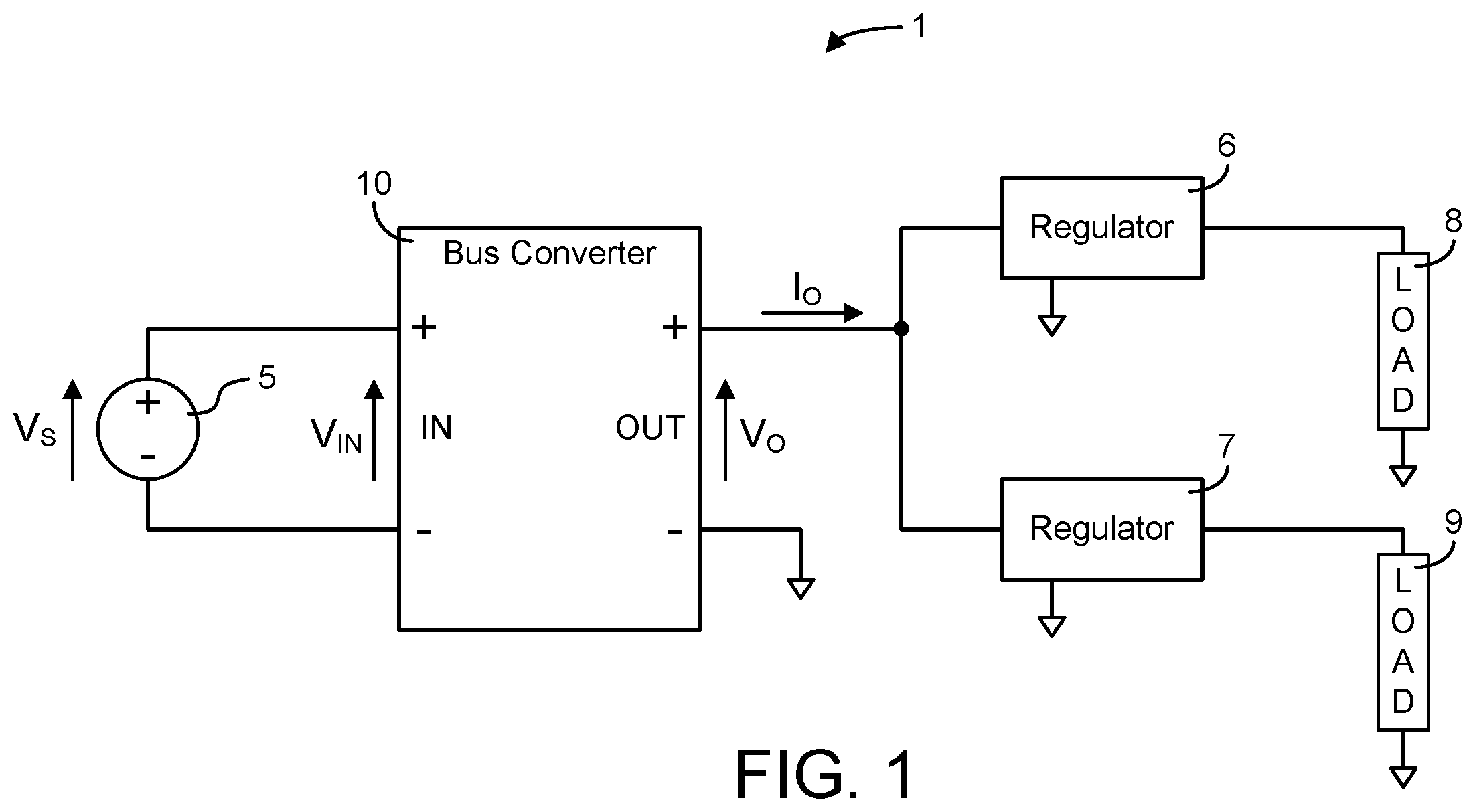
Referring to , a prior art power distribution system 1 such as an Intermediate Bus Architecture (“IBA”) is shown having a DC power source 5 , supplying power at a source voltage, V S , to the input of a bus converter 10 . The output of the bus converter 10 supplies power to one or more down-stream regulators, e.g. regulators 6 , 7 which in turn provide regulated power, e.g. regulated voltage, to respective loads 8 , 9 . The bus converter 10 may include a DC Transformer which is a switching power converter that may provide voltage transformation from its input to output at an essentially fixed voltage gain and also provide galvanic isolation between its input and output. The bus converter 10 may adjust its output slightly during predetermined operating conditions to provide in-rush current limiting, e.g. during start up and may provide partial regulation over selected portions of the source voltage range. Although a single bus converter is shown in , a plurality of bus converters may be connected to receive power from a single source 5 and provide power at one or more voltages to a plurality of down-stream regulators, such as regulators 6 and 7 . Additionally, two or more bus converters or two or more DC Transformers may be connected in parallel to increase power throughput or to provide a measure of fault tolerance.
SUMMARY
One embodiment of the disclosure relates to an apparatus that includes a power distribution system comprising a source for providing power at a DC source voltage V S . The apparatus further includes a bus converter that includes an input circuit and an output circuit. The bus converter is adapted to convert power from the input circuit to the output circuit at a substantially fixed voltage transformation ratio K DC at an output current. An input voltage V IN is applied to the input circuit and an output voltage V OUT is produced by the output of the bus converter, and the substantially fixed voltage transformation ratio can be represented as K DC =V OUT /V IN . The apparatus further includes a power distribution bus connected to distribute power from the output circuit of the bus converter at the output voltage V OUT . The apparatus further includes a plurality of regulators. Each regulator includes a regulator input connected to the power distribution bus to receive power from the output circuit of the bus converter and a regulator output connected to supply power to a respective load. The plurality of regulators each are separated by a distance from the bus converter. The input circuit of the bus converter and at least a portion of the output circuit of the bus converter are connected in series across the source such that an absolute value of the input voltage V IN applied to the input circuit is approximately equal to the absolute value of the DC source voltage V S minus a number N times the absolute value of the output voltage V OUT , where Nis at least 1.
Another embodiment relates to an apparatus that includes a power converter including an input circuit and an output circuit. The power converter is configured to receive power from a power distribution system comprising a source for providing power at a DC source voltage V S . The power converter is adapted to convert power from the input circuit to the output circuit at a substantially fixed voltage transformation ratio K DC at an output current. An input voltage V IN is applied to the input circuit and an output voltage V OUT is produced by the output of the power converter. The substantially fixed voltage transformation ratio can be represented as K DC =V OUT /V IN . The power converter further includes a series connection between the input circuit of the power converter and at least a portion of the output circuit of the power converter across the source, such that an absolute value of the input voltage V IN applied to the input circuit is approximately equal to the absolute value of the DC source voltage V S minus a number N times the absolute value of the output voltage V OUT , where N is at least 1.
Yet another embodiment relates to an apparatus that includes a bus converter including an input circuit and an output circuit. The bus converter is configured to receive power from a power distribution system including a source for providing power at a DC source voltage V S . The bus converter is adapted to convert power from the input circuit to the output circuit at a substantially fixed voltage transformation ratio K DC at an output current. An input voltage V IN is applied to the input circuit and an output voltage V OUT is produced by the output of the bus converter, and the substantially fixed voltage transformation ratio can be represented as K DC =V OUT /V IN . The apparatus further includes a power distribution bus connected to distribute power from the output circuit of the bus converter at the output voltage V OUT . The apparatus further includes a plurality of regulators. Each regulator includes a regulator input connected to the power distribution bus to receive power from the output circuit of the bus converter and a regulator output connected to supply power to a respective load. The plurality of regulators each are separated by a distance from the bus converter. The input circuit of the bus converter and at least a portion of the output circuit of the bus converter are connected in series across the source such that an absolute value of the input voltage V IN applied to the input circuit is approximately equal to the absolute value of the DC source voltage V S minus a number N times the absolute value of the output voltage V OUT , where N is at least 1.
Another embodiment relates to an apparatus comprising an intermediate bus architecture power distribution system for a telecommunications system comprising a source for providing power at a DC source voltage; a circuit board comprising a bus converter, the bus converter comprising an input circuit, the input circuit comprising a primary transformer winding, the bus converter further comprising an output circuit, the output circuit comprising a secondary transformer winding, wherein the primary and secondary transformer windings are galvanically connected in series, and wherein the bus converter is configured to provide power to a power distribution bus that is not galvanically isolated from the source; and the circuit board further comprising a plurality of regulators, wherein each regulator comprises a regulator input connected to the power distribution bus to receive power from the output circuit of the bus converter and a regulator output connected to supply power to a respective load, the plurality of regulators each being separated by a distance from the bus converter.
BRIEF DESCRIPTION OF THE DRAWINGS
shows a schematic block diagram of a prior art IBA power distribution system according to an illustrative embodiment.
shows a functional block diagram of a series-connected DC Transformer according to an illustrative embodiment.
shows a schematic diagram of a new power distribution architecture according to an illustrative embodiment.
shows a schematic diagram of an isolated SAC-based DC Transformer according to an illustrative embodiment.
shows a schematic diagram of a series-connected SAC-based DC Transformer according to an illustrative embodiment.
shows a schematic diagram of a series-connected SAC-based DC Transformer having a center-tapped winding in the output circuit according to an illustrative embodiment.
shows a schematic diagram of a series-connected DC Transformer for receiving power from a negative input source and delivering power at a positive output voltage according to an illustrative embodiment.
DETAILED DESCRIPTION
Power Distribution Architecture
A power distribution system 50 is shown in having a primary power source 51 delivering power via a connection 52 to a front-end power-processing unit 53 . The primary power source 51 may be an AC utility line, and the front end unit 53 may be a power conversion stage that converts power from the power source 51 delivering power at a relatively high but safe DC voltage to a power distribution bus 55 , e.g. the DC voltage may vary from a minimum, e.g. 38 Volts, to a maximum, e.g. 55 Volts. Preferably, the front-end unit 53 provides voltage step down and isolation and may optionally provide power factor correction, regulation, or both. An optional backup power system 54 is shown connected to the power distribution bus 55 to provide power in the event of a loss of power from the primary power source 52 . The backup power system may include batteries, a charger for maintaining the batteries, and a switchover mechanism that connects the batteries to the bus in response to predetermined events, such as a decline in voltage or loss of power from the output of the front end 53 or the primary power source 51 .
One or more bus converters, e.g. bus converters 56 , 57 , may be connected to the power distribution bus 55 downstream from the front end 53 as shown in the example of to convert power received from the relatively high voltage power distribution bus 55 for delivery to a respective lower voltage bus. As shown, bus converters 56 and 57 respectively supply power to buses 58 and 59 at voltages, e.g. at or near the requisite load voltages, that are lower than the voltage of the power distribution bus 55 , providing step-down voltage transformation. The bus converters 56 , 57 are generally separated by a distance from their respective regulators 60 , 61 . For example, in a typical system, one or more system circuit boards housed in a common enclosure may each include one or more bus converters, preferably located near the edge of, or other location on, the board where power connections are made to the board. A down-stream regulator receiving power from the bus converter(s) may be preferably located adjacent to the circuitry, e.g. a processor, ASIC, or other circuitry, to which it or they supply power. The physical distance separating the bus converter and a respective down-stream regulator in such an example may range from as much as a dimension of the system circuit board, i.e. a diagonal dimension where the bus converter and regulator located at opposite corners, a length or width dimension where they are located at opposite edges, a half-length or width where one is situated closer to the middle and the other is at an edge, etc. In another example, a bus converter may be located off of the system board in which case the electrical distance could be greater than a dimension of the system board. Naturally, the distance separating the bus converter and a respective down-stream regulator will depend on the system layout. However, a bus converter housed in a self-contained assembly adapted to be installed as a unit at a location remote from the down-stream regulator(s) may be separated by a distance from a down-stream regulator regardless of their respective mounting locations at the system level.
The output of each bus converter 56 , 57 may, in turn, provide power via its respective bus 58 , 59 to a respective plurality of regulators, preferably at or near the point of load, such as point-of-load switching voltage regulators 60 , 61 . It should be understood that although two bus converters 56 , 57 are shown in the example of , any number of bus converters, e.g. one, may be used. Similarly, although regulators 60 and 61 are shown in as comprising a plurality of individual regulators, any suitable number of regulators, e.g. one, may be connected to a particular bus converter within the constraints of the physical devices used. The regulators 60 , 61 may supply power to respective loads (not shown). The loads can be a variety of devices, including integrated circuits and electromechanical devices (such as storage and cooling devices).
The bus converters 56 , 57 shown in the system of , however, preferably do not provide galvanic isolation between their respective output busses 58 , 59 and the power distribution bus 55 as described in additional detail below.
Series-Connected DC Transformer
Referring to , a functional block diagram of a series-connected power conversion system 20 suitable for use as a bus converter in the power distribution system 50 of is shown. The power conversion system 20 includes an input 21 for receiving power from a source at a source voltage, V S , and an output 22 for delivering power to a load at an output voltage, V O , that is less than V S , and a DC Transformer 25 . The DC Transformer 25 may be implemented preferably using the Sine-Amplitude Converter (“SAC”) topologies and timing architectures described in Vinciarelli, Factorized Power Architecture and Point of Load Sine Amplitude Converters, U.S. Pat. No. 6,930,893 and in Vinciarelli, Point of Load Sine Amplitude Converters and Methods, U.S. Pat. No. 7,145,786 both assigned to VLT., Inc. and incorporated here in their entirety by reference (hereinafter the “SAC Patents”). Alternatively, other converter topologies, such as hard-switching, fixed ratio DC-DC converters, may be used. The DC Transformer 25 converts power received from its input 23 (distinguished from the input 21 of the bus converter 20 ) at an input voltage, V IN , for delivery to its output 24 at an output voltage, V OUT , using an essentially fixed voltage gain or voltage transformation ratio.
The voltage gain or voltage transformation ratio of a system as defined generally herein is the ratio of its output voltage to its input voltage at a specified current such as an output current. For the system 20 in , the voltage transformation ratio may be expressed as K SYS =V O /V S @ I L . Similarly, the voltage transformation ratio of the DC Transformer 25 may be stated as K DC =V OUT /V IN @ I O . Note that the system output voltage, V O , and the DC Transformer output voltage, V OUT , are the same in the configuration shown. However, the input 23 and output 24 of the DC Transformer 25 are shown in a series-connected configuration across the system input 21 . As a result, the input voltage, V IN , to the DC Transformer input 23 is less than the input voltage, V S , to the system input 21 by an amount equal to the output voltage: V IN =V S −V O . (1)
Similarly as shown in , the current, I L , drawn by the load from the system output 22 is greater than the current produced at the output 24 of the DC Transformer 25 by an amount equal to the input current: I O =I L −I IN . (2)
The system voltage transformation ratio, K SYS , using the series-connected DC Transformer 25 , may be expressed as a function of the DC Transformer voltage transformation ratio, K DC : K SYS =K DC /( K DC +1) (3)
The above equation (3) may be rearranged to express the DC Transformer 25 voltage transformation ratio, KDC, required in a series-connected system as a function of the system voltage transformation ratio, K SYS : K DC =K SYS /(1− K SYS ) (4)
Referring to , an isolated SAC that may be utilized for DC Transformer 25 , according to one embodiment, is shown having a full-bridge input circuit, including switches S1, S2, S3, and S4, connected to drive the resonant circuit including capacitor C and the input winding, having N1 turns, with the input voltage V IN . The isolated SAC is shown having a full-bridge output circuit, including switches S5, S6, S7, and S8, connected to rectify the voltage impressed across the output winding, having N2 turns, and delivering the output voltage, V O . The voltage transformation ratio of the SAC will be essentially a function of the turns ratio: K DC =V O /V IN =N2/N1.
A series-connected SAC 200 is shown in . By way of comparison, the series-connected SAC 200 uses the same full-bridge input circuit topology, including switches S1, S2, S3, and S4, driving the resonant circuit including capacitor C and the input winding, having N1 turns, with the input voltage V IN . SAC 200 also uses the same full-bridge output topology, including switches S5, S6, S7, and S8, connected to rectify the voltage impressed across the output winding, having N2 turns, and delivering the output voltage, V O . The voltage transformation ratio of the series-connected SAC 200 from the input circuit to output circuit is also essentially a function of the transformer turns ratio N2/N1 and the same as the isolated SAC 25 in : K DC =V O /V IN =N2/N1. However, when evaluated in terms of the system, i.e. using V S applied across the series-connected input and output, the voltage transformation ratio becomes: K SYS =V O /V S =N2/(N2+N1).
Many contemporary applications use a voltage transformation ratio equal to ⅕ requiring an odd transformer turns ratio (N2/N1=⅕) which is generally not optimal. Referring to equation (4) above, the K SYS =⅕ bus converter may be implemented using a K DC =¼ series-connected topology (e.g. as shown in , 4 , and 5 ), allowing the use of an even, i.e. 1:4, turns ratio in the transformer. An even transformer turns ratio may provide greater transformer layout flexibility and efficiency.
Note that the series-connected converter 200 may be implemented by connecting an off-the-shelf isolated DC Transformer, such as the isolated converter shown in , as shown in . Alternatively, the converter 200 may be implemented as series-connected input and output circuits, e.g. as shown in , 6 , and 7 discussed below, in an integrated converter, optionally providing greater power density eliminating the isolation imposed design constraints, eliminating control circuit bias currents from flowing through to the output and the potential need for an output clamp, and providing system-ground referenced control circuitry (not shown) for interface signals that are referenced to ground rather than the output for the reconfigured off-the-shelf isolated converter.
Connecting the input and output of the DC Transformer 25 in series eliminates galvanic isolation between the input and output of the series-connected bus converter 20 , which is counterintuitive. However, when used in the architecture of , isolation is deployed at an intermediate stage where the isolation may be superfluous. The architecture of , therefore, trades isolation at this stage for efficiency gain and reduced component stress. If isolation is required, e.g. for safety reasons, in the architecture of , it may preferably be provided by an upstream power conversion stage such as the front-end converter 53 .
Efficiency
The power processed by the isolated SAC shown in may be compared with that of the series-connected SAC 200 ( ) by summing the product of maximum voltage across (V n ) and average current (I n ) through each switch (n=1 through 8).
P Processed = ∑ n = 1 n = 8 n ( Vn * In ) ( 5 )
Each input switch (S1, S2, S3 and S4) in the full bridge input circuits ( , 5 ) is subjected to the input voltage, V IN , (distinguished from the source voltage V S ) and an average of one half of the input current, I IN . The sinusoidal nature of the current in the SAC topology represents a difference between the RMS and average currents, which is unimportant for the following comparison between two converters using the same topology. The power processed by the input circuits is: P IN =2* V IN *I IN (6)
Similarly, each output switch (S5, S6, S7 and S8) in the full bridge output circuit of will be subjected to the full output voltage, V O , and will carry an average of one half of the output current, I O . Note that the output current in the case of the isolated converter is equal to the load current, I L and in the case of the series-connected converter (discussed below) is not. The power processed by the output circuits may therefore be reduced to: P OUT =2* V O *I O (7)
Combining equations (6) and (7) and making the appropriate substitutions using K DC =V O /V IN and the corollary I IN =K DC *I O , the total power processed by the converters reduces to: P= 4* V O *I O (8)
In the isolated converter of , the output current equals the load current (I O =I L ), therefore, the power processed by the isolated converter, P ISO , may be reduced to the following function of load power, P Load =V O *I L : P ISO =4* P Load (9)
Neglecting fixed losses in the converter, the input current may be expressed as a function of the output current and voltage transformation ratio as follows: I IN =I O *K DC (10)
Combining equations (2), (4), and (10), the output current of the series-connected converter may be expressed as a function of load current and voltage transformation ratio as follows: I O-Series =I L *(1− K SYS ) (11)
Substituting equation (11) into equation (8) produces the total power processed by the series-connected converter as a function of load power (P Load =V O *I L ) and system voltage transformation ratio: P SERIES =4* P Load *(1− K SYS ) (12)
Accordingly, the efficiency advantage of the series-connected converter over the isolated converter—the ratio of equations (12) and (9)—reduces to: P SERIES /P ISO =(1− K SYS ) (13)
From equation (13) it can be seen that the series-connected converter offers a significant efficiency advantage. Consider a typical example for comparison, using a bus converter to convert power from a nominal 50 Volt power distribution bus for delivery to a 10 volt load (K SYS =⅕) at 100 amps: the series-connected converter processes only 80% of the power, offering a 20% efficiency savings compared to the isolated converter.
In a typical isolated DC Transformer, like most DC-DC converters, the control circuitry is configured to operate from power drawn from the input producing a quiescent component of the input current. Use of such a converter, e.g. an off-the-shelf DC Transformer, in a series-connected configuration could, therefore, allow the quiescent input current to flow unregulated into a load connected to the output, which would be problematic while the power train is not operating and, therefore, incapable of regulating the output voltage. It may, for that reason, be desirable to clamp the output voltage using a zener diode, such as zener diode 26 in , or other clamp circuit or device appropriately scaled in breakdown voltage and power dissipation to carry the quiescent input current, protecting the load and perhaps the output circuitry of the converter. Integrating the series-connected input and output circuitry into a non-isolated converter topology such as shown in , 6 , and 7 affords the opportunity to configure the control circuitry to draw power from the input to ground preventing that component of the input current from flowing out to the load. Additionally, a DC blocking capacitor may be used in the power train to avoid leakage current from flowing from the input to the output. One or both of the above measures may be used to avoid the need to clamp the output.
Configuring the control circuitry to reference the system ground in the integrated converter (rather than the input return in the off-the-shelf isolated converter) easily allows any interface signals to be ground-referenced (rather than output referenced) which is advantageous from the perspective of the system integrator.
Center-Tap Secondary
Another series-connected SAC 210 is shown in . By way of comparison, the series-connected SAC 210 uses the same full-bridge input circuit topology, including switches S1, S2, S3, and S4, driving the resonant circuit including capacitor C and the input winding, having N1 turns, with the input voltage V IN , as shown in . However, a center-tap output winding, having 2*N2 turns, is used in the output circuit, which includes switches S5, S6, S7, and S8, connected to rectify the voltage impressed across the output windings and delivering the output voltage, V O . The system voltage transformation ratio of the series-connected SAC 210 ( ) is essentially a function of the transformer turns ratio: K SYS =V O /V SYS =N2/(N1+2*N2); as is the voltage transformation ratio from input circuit to output circuit: K DC =V O /V IN =N2/N1.
The converter 210 of differs from the series-connected converter 200 ( ) in that the input voltage, V IN , presented to the input circuit is equal to the source voltage, V S , reduced by twice the output voltage, V O : V IN-210 =V S −2 V O (14) as suggested by the addition of N2 turns in the output winding of the transformer. Also, each output switch (S5, S6, S7 and S8) in the converter 210 is subjected to twice the output voltage, V O , with the upper output switches (S5 and S7) each carrying an average of half of the input current, I IN , and the lower output switches (S6 and S8) each carrying an average of half of the difference between the load current, I L , and the input current, I IN . Using the same analysis as described above, summing the product of maximum voltage across (V n ) and average current (I n ) through each switch (N=1 through 8), the total power processed by the converter 210 of is: P 210 =2* V IN *I IN +2* V O *I IN +2* V O *( I L −I IN ) (15)
Using the system voltage transformation ratio, K SYS =V O /V S in equation (14), the input voltage may be expressed as: V IN-210 =V O *((1/ K SYS )−2) (16)
Recognizing that in an ideal converter the input power equals the output power V S *I IN =V O *I L the input current may be expressed as: I IN =K SYS *I L (17)
Making the appropriate substitutions into equation (15), the total power processed by series-connected converter 210 ( ) reduces to: P 210 =4* V O *I L *(1− K SYS ) (18) which may be further reduced to express the total power processed by the series-connected converter 210 using a center-tap output winding as shown in as a function of load power (P Load =V O *I L ) and system voltage transformation ratio: P 210 =4* P Load *(1− K SYS ) (19)
Which is the same result obtained in equation (12) above for the series-connected converter 200 in .
There may be certain advantages of one series-connected topology over the other depending upon the application. For example, the transformer in the converter 200 ( ) has N2 fewer turns than in the transformer of the converter 210 ( ) offering reduced winding losses. However, the input switches (S1, S2, S3 and S4) in the converter 210 ( ) are exposed to lower voltages than in the converter 200 ( ) which may afford lower switch conduction losses. Also, two of the output switches (S5 and S7) in converter 210 ( ) carry much less current and may be implemented with smaller and more cost effective devices than in converter 200 ( ).
Negative Input-Positive Output
Referring to , another series-connected SAC-based converter 215 is shown configured to receive a negative source voltage, V S , and deliver a positive output voltage. (The topology shown in may alternatively be adapted to receive a positive source voltage and deliver a negative output voltage.) Converter 215 may be viewed as a variation of the converter 210 ( ) in which the input and output circuit positions have been rearranged with the output terminal serving as the common terminal. The converter 215 of differs from the converter 210 ( ) in that the absolute value of the input voltage, V IN , presented to the input circuit is equal to the absolute value of the source voltage, V S , reduced by the absolute value of the output voltage, V O (compared to twice the output voltage in ) because of the polarity change from input to output: | V IN-215 |=|V S |−|V O | (20) as also suggested by the transformer configuration. Also, the upper output switches (S5 and S7) each carry an average of half of the output current, I O , which equals the load current, I L in , compared to the difference between the load current, I L , and the input current, I IN , in . Once again, summing the product of maximum voltage across (V n ) and average current (I n ) through each switch (N=1 through 8) as described above, the total power processed by the converter 215 of is: P 215 =2* V IN *I IN +2* V O *I IN +2* V O *I L (21) which, when reduced using equations (17) and (20), becomes: P 215 =4* P Load (22)
A comparison of the power processed by the converter 215 (equation (22); ) with the power processed by the isolated converter 25 (equation (9); ) may indicate no efficiency advantage, however, the input switches (S1, S2, S3 and S4) in the series-connected converter 215 of are subjected to lower voltages potentially affording use of better figure of merit switches leading to potential efficiency improvements. Furthermore, the absence of isolation-related design constraints in such an integrated converter may be used to increase power density.
The converters 20 ( ), 200 ( ), 210 ( ), and 215 ( ) are examples of a class of series-connected converters in which at least a portion of the output circuit is connected in series with the input circuit such that the absolute value of the voltage, V IN , presented to the input circuit is equal to the absolute value of the source voltage V S , minus N times the absolute value of the output voltage, V O , where the value of N is at least 1: | V IN |=|V S |−N*|V O | (23)
The value of N will vary depending upon the converter topology used, e.g. a center-tap secondary or not, polarity reversing or not, etc. In the examples described above: N=1 for converters 20 ( ), 200 ( ), and 215 ( ) and N=2 for converter 210 ( ) as shown in equation 14. Although a full bridge switch configuration is preferred for its superior noise performance, half-bridge switch configurations may also be deployed in the input circuitry, the output circuitry, or both.
The disclosure is described above with reference to drawings. These drawings illustrate certain details of specific embodiments that implement the systems, apparatus, and/or methods of the present disclosure. However, describing the disclosure with drawings should not be construed as imposing on the disclosure any limitations that may be present in the drawings. No claim element herein is to be construed under the provisions of 35 U.S.C. § 112, sixth paragraph, unless the element is expressly recited using the phrase “means for.” Furthermore, no element, component or method step in the present disclosure is intended to be dedicated to the public, regardless of whether the element, component or method step is explicitly recited in the claims.
It should be noted that although the disclosure provided herein may describe a specific order of method steps, it is understood that the order of these steps may differ from what is described. Also, two or more steps may be performed concurrently or with partial concurrence. It is understood that all such variations are within the scope of the disclosure.
The foregoing description of embodiments of the disclosure have been presented for purposes of illustration and description. It is not intended to be exhaustive or to limit the disclosure to the precise form disclosed, and modifications and variations are possible in light of the above teachings or may be acquired from practice of the disclosure. The embodiments were chosen and described in order to explain the principals of the disclosure and its practical application to enable one skilled in the art to utilize the disclosure in various embodiments and with various modifications as are suited to the particular use contemplated.
Figures (7)
Citations
This patent cites (864)
- US443441
- US1181803
- US2042274
- US2497534
- US2852730
- US2902862
- US2953738
- US3008068
- US3008506
- US3029398
- US3083328
- US3141140
- US3146406
- US3161837
- US3174042
- US3229111
- US3241035
- US3295042
- US3307073
- US3313996
- US3343073
- US3400325
- US3435375
- US3443194
- US3448370
- US3454853
- US3458798
- US3459957
- US3471747
- US3495157
- US3506908
- US3514692
- US3517301
- US3553428
- US3564393
- US3569818
- US3573483
- US3573494
- US3573508
- US3573544
- US3573597
- US3579026
- US3581186
- US3582754
- US3582758
- US3584289
- US3588595
- US3599073
- US3604920
- US3619713
- US3629648
- US3629725
- US3638099
- US3643152
- US3646395
- US3657631
- US3660672
- US3663941
- US3665203
- US3668508
- US3684891
- US3696286
- US3704381
- US3710231
- US3714545
- US3733538
- US3735235
- US3737755
- US3742242
- US3743861
- US3751676
- US3753071
- US3753076
- US3754177
- US3757195
- US3769545
- US3771040
- US3781505
- US3781638
- US3787730
- US3805094
- US3816810
- US3818237
- US3818312
- US3820008
- US3824450
- US3845404
- US3848175
- US3851240
- US3851278
- US3859638
- US3873846
- US3879647
- US3879652
- US3904950
- US3909695
- US3909700
- US3912940
- US3913002
- US3913036
- US3916289
- US3919656
- US3927363
- US3930196
- US3932764
- US3938024
- US3940682
- US3949238
- US3959716
- US3974397
- US3976932
- US3986052
- US3986097
- US3989995
- US3991319
- US4005335
- US4007413
- US4010381
- US4011518
- US4017746
- US4017783
- US4017784
- US4027228
- US4037271
- US4044268
- US4051445
- US4058369
- US4060757
- US4066945
- US4074182
- US4078247
- US4104539
- US4106084
- US4109192
- US4114048
- US4115704
- US4122359
- US4126793
- US4128868
- US4131860
- US4140959
- US4150423
- US4177389
- US4184197
- US4187458
- US4194147
- US4205368
- US4207475
- US4208594
- US4208706
- US4209710
- US4210858
- US4210958
- US4238690
- US4238691
- US4241261
- US4245194
- US4245286
- US4251857
- US4253136
- US4254459
- US4257087
- US4257089
- US4262214
- US4268476
- US4270164
- US4270165
- US4272806
- US4274133
- US4275317
- US4276594
- US4277726
- US4277728
- US4288739
- US4288865
- US4292581
- US4293902
- US4293904
- US4297590
- US4300191
- US4301496
- US4302803
- US4307441
- US4310771
- US4313060
- US4315207
- US4316097
- US4317056
- US4318007
- US4318164
- US4322817
- US4323787
- US4323788
- US4323962
- US4325017
- US4327298
- US4328482
- US4330816
- US4334263
- US4336587
- US4344122
- US4344124
- US4346342
- US4347558
- US4353113
- US4355884
- US4356541
- US4357654
- US4368409
- US4371919
- US4381457
- US4386394
- US4393316
- US4395639
- US4398156
- US4399499
- US4403269
- US4415960
- US4423341
- US4427899
- US4438411
- US4441070
- US4442339
- US4443840
- US4449173
- US4449174
- US4449175
- US4451743
- US4451876
- US4465966
- US4471289
- US4473756
- US4476399
- US4479175
- US4484084
- US4499531
- US4504895
- US4519024
- US4520296
- US4523265
- US4524411
- US4524413
- US4527228
- US4528459
- US4533986
- US4535399
- US4536700
- US4538073
- US4538101
- US4539487
- US4546421
- US4553039
- US4556802
- US4561046
- US4562522
- US4564800
- US4566059
- US4571551
- US4575640
- US4578631
- US4584635
- US4586119
- US4587604
- US4591782
- US4593213
- US4605999
- US4607195
- US4607323
- US4618919
- US4621313
- US4622511
- US4622629
- US4626982
- US4628426
- US4635179
- US4638175
- US4642475
- US4642743
- US4644440
- US4648017
- US4651020
- US4652769
- US4659942
- US4663699
- US4670661
- US4672517
- US4672518
- US4672528
- US4674019
- US4675796
- US4677311
- US4677534
- US4680688
- US4680689
- US4683528
- US4685039
- US4688160
- US4691273
- US4694384
- US4694386
- US4695935
- US4697136
- US4698738
- US4706177
- US4709316
- US4709318
- US4716514
- US4717833
- US4727308
- US4727469
- US4730242
- US4733102
- US4734839
- US4734844
- US4734924
- US4745299
- US4745538
- US4747034
- US4748550
- US4754160
- US4754161
- US4760276
- US4763237
- US4768141
- US4772994
- US4777382
- US4777575
- US4779185
- US4782241
- US4783728
- US4785387
- US4788450
- US4788634
- US4794506
- US4796173
- US4800479
- US4805078
- US4809148
- US4811191
- US4812672
- US4814962
- US4814965
- US4823249
- US4825348
- US4829216
- US4833582
- US4841160
- US4853832
- US4853837
- US4855858
- US4855888
- US4860184
- US4860185
- US4860188
- US4860189
- US4864479
- US4864483
- US4866588
- US4866589
- US4868729
- US4870555
- US4873616
- US4873618
- US4877972
- US4881014
- US4882646
- US4882664
- US4882665
- US4885674
- US4890210
- US4890214
- US4893227
- US4893228
- US4896092
- US4899271
- US4900885
- US4902508
- US4903183
- US4903189
- US4908857
- US4916599
- US4920470
- US4922397
- US4922404
- US4924170
- US4926303
- US4929605
- US4931918
- US4935857
- US4937468
- US4952849
- US4953068
- US4958268
- US4959764
- US4959766
- US4961128
- US4975823
- US4982149
- US5001318
- US5006782
- US5008795
- US5010261
- US5012401
- US5013980
- US5016245
- US5017800
- US5019717
- US5019719
- US5019954
- US5023766
- US5027002
- US5027264
- US5029062
- US5036452
- US5038264
- US5038265
- US5038266
- US5041777
- US5043859
- US5047911
- US5055722
- US5057698
- US5057986
- US5063338
- US5063489
- US5066900
- US5073848
- US5077486
- US5079686
- US5097403
- US5099406
- US5101336
- US5103110
- US5103387
- US5105351
- US5111372
- US5111374
- US5113334
- US5113337
- US5119013
- US5119283
- US5119284
- US5122726
- US5122945
- US5126651
- US5128603
- US5132888
- US5132889
- US5138184
- US5138249
- US5140509
- US5140512
- US5140514
- US5144547
- US5146394
- US5157269
- US5159541
- US5161241
- US5162663
- US5164609
- US5168435
- US5173846
- US5177675
- US5179512
- US5206800
- US5208740
- US5216351
- US5218522
- US5221887
- US5224025
- US5233509
- US5235502
- US5237208
- US5237606
- US5254930
- US5255174
- US5264736
- US5267135
- US5267137
- US5268830
- US5272612
- US5272613
- US5274539
- US5274543
- US5289364
- US5303138
- US5304875
- US5305191
- US5305192
- US5343383
- US5353212
- US5355077
- US5355293
- US5355294
- US5363323
- US5377090
- US5383858
- US5386359
- US5396403
- US5396412
- US5398182
- US5400239
- US5410467
- US5412308
- US5412557
- US5424932
- US5428523
- US5430632
- US5430633
- US5434770
- US5438499
- US5442534
- US5448469
- US5461301
- US5477091
- US5481178
- US5481449
- US5500791
- US5513092
- US5514921
- US5519599
- US5528480
- US5528482
- US5530635
- US5534768
- US5535112
- US5537021
- US5539630
- US5539631
- US5541827
- US5552695
- US5559423
- US5559682
- US5570276
- US5576940
- US5590032
- US5594629
- US5621621
- US5625541
- US5635826
- US5636107
- US5636116
- US5663876
- US5663877
- US5663887
- US5691870
- US5708571
- US5719754
- US5726869
- US5729444
- US5734563
- US5736843
- US5742491
- US5745359
- US5754414
- US5757625
- US5757627
- US5768118
- US5771160
- US5774350
- US5781420
- US5781421
- US5784266
- US5805432
- US5818704
- US5831839
- US5841641
- US5841643
- US5862042
- US5870299
- US5872705
- US5880939
- US5880949
- US5894412
- US5901052
- US5903452
- US5907481
- US5916313
- US5929692
- US5946202
- US5946207
- US5949658
- US5956242
- US5956245
- US5959370
- US5991167
- US5999417
- US6002597
- US6005773
- US6011703
- US6016258
- US6016261
- USRE36571
- US6026005
- US6038148
- US6046920
- US6058026
- US6066943
- US6069799
- US6069804
- US6084792
- US6087817
- US6088329
- US6091616
- US6137697
- US6137698
- US6141224
- US6169675
- US6191964
- US6208535
- US6211657
- US6222742
- US6246592
- US6252781
- US6262890
- US6278621
- USRE37510
- US6370050
- US6385059
- US6417653
- US6421262
- US6430071
- USRE37889
- US6466454
- USRE37898
- US6477065
- US6487093
- US6504267
- US6535407
- US6552917
- US6580258
- US6594159
- US6608768
- US6696882
- US6700365
- US6721192
- US6724631
- US6728118
- US6731520
- US6735094
- US6804125
- US6836415
- US6845019
- US6853563
- US6853568
- US6862194
- US6862195
- US6862198
- US6927987
- US6930893
- US6965517
- US6970366
- US6970367
- US6984965
- US6987679
- US7019997
- US7031128
- US7035120
- US7050309
- US7055309
- US7061775
- US7072190
- US7145786
- US7184280
- US7187562
- US7230405
- US7236368
- US7269034
- US7272023
- US7307857
- USRE40438
- US7403397
- US7428159
- US7501715
- US7558083
- US7564702
- US7727021
- US7746041
- US7768801
- US7855905
- US8023290
- US8243473
- US8493751
- US8582333
- US8749990
- US9087656
- US9166481
- US9516761
- US10199950
- US10374505
- US10594223
- US11075583
- US2003/0007372
- US2003/0174522
- US2004/0100778
- US2005/0047177
- US2006/0209572
- US2006/0220938
- US2006/0262575
- US2006/0285368
- US2006/0290689
- US2007/0076377
- US2008/0175024
- US2008/0211304
- US2009/0051221
- US2009/0243079
- US2010/0091526
- US2010/0232180
- US2010/0259241
- US2011/0057713
- US2011/0176333
- US2012/0155104
- US2013/0121033
- US2013/0163287
- US2014/0085939
- US2021/0155104
- US1181803
- US2042274
- US29 02 862
- US0 165 37
- US0 418 83
- US0 779 58
- US0 584 00
- US0 184 963
- US0 223 504
- US0 102 614
- US0 139 870
- US0 244 186
- US0 289 196
- US0 343 855
- US0 410 866
- US0 449 504
- US0 467 778
- US0 472 261
- US0 481 466
- US0 484 610
- US0 291 403
- US0 549 920
- US0 550 167
- US0 582 814
- US0 588 569
- US0 257 817
- US0 336 725
- US0 605 752
- US0 608 091
- US0 610 158
- US0 616 281
- US0 622 891
- US0 549 920
- US0 665 634
- US0 687 058
- US0 428 377
- US0 694 826
- US0 696 831
- US0 529 180
- US0 474 471
- US0 709 949
- US0 476 278
- US0 720 278
- US0 736 959
- US0 741 447
- US0 595 232
- US0 599 814
- US0 848 485
- US0 508 664
- US0 429 310
- US0 757 428
- US0 575 626
- US0 884 829
- US0 503 806
- US0 944 162
- US0 954 088
- US0 973 246
- US0 996 219
- US0 618 666
- US0 925 638
- US0 798 846
- US0 932 929
- US0 851 566
- US0 805 540
- US0 854 564
- US1 231 705
- US2535133
- US2608857
- US2 217 931
- US2 110 493
- US2 117 144
- US2 131 238
- US2 160 722
- US2 233 479
- US2 244 155
- US2 255 865
- US2 291 287
- US2 313 495
- USS6149583
- US61-273171
- US61-277372
- US62-233067
- US63-257458
- US63-277471
- USS6450762
- USH01-278265
- USH01-283061
- USH02-155465
- USH02-202362
- USH02-246774
- USH318275
- USH389851
- US04-105556
- USH05-064446
- US05-199744
- US05-207745
- US06-098540
- US06-187056
- US06-315263
- US06-339266
- USH06-343262
- US07-007928
- US07-115766
- US07-194104
- US07-308062
- US07-337005
- US07-337006
- US08-019251
- US08-205533
- US08-223906
- US08-275518
- US08-289538
- US08-336282
- US09-093917
- US09-172775
- US09-182416
- USH07-337005
- US10-066336
- US10-136646
- US10-146054
- US10-210740
- US10-248248
- US11-004577
- US11-069803
- US11-103572
- US11-146650
- USH11-134989
- US11-178335
- US2004-254393
- US2012-034522
- US177578
- USWO-84/04634
- USWO-86/02787
- USWO-87/05165
- USWO-88/09084
- USWO-89/01719
- USWO-91/07803
- USWO-95/23451
- USWO-95/30182
- USWO-95/32458
- USWO-98/11658
- USWO-98/18198
- USWO-98/26496
- USWO-98/33267
- USWO-01/97371
- USWO-2004/082119
- USWO-2005/008872
- US9711503