Joint Structure and Assembly Method for Same
Abstract
A joint structure includes a connection member provided between a reinforced member and a reinforcing member and connecting both of them to each other. The connection member includes a first coupling portion and a second coupling portion that are coupled to one and another of the reinforced member and the reinforcing member, respectively. The first coupling portion is coupled to a joint portion of one of the reinforced member and the reinforcing member by an adhesive or welding. The first coupling portion and the joint portion are shaped so as to be caught by each other in a joining direction in which the reinforced member and the reinforcing member are joined to each other.
Claims (9)
1. A joint structure in which a reinforced member and a reinforcing member are coupled to each other, the joint structure comprising: a plurality of elastically deformable connection members provided between the reinforced member and the reinforcing member and connecting the reinforced member and the reinforcing member to each other, the reinforced member, the reinforcing member, and each of the plurality of connection members are mutually different members, the reinforced member includes an attachment surface to which the plurality of connection members are attached, a first direction and a second direction defined, with respect to the attachment surface, as being perpendicular to each other wherein the reinforcing member extends in an elongated shape in a position selected in the first direction, along the second direction, the reinforcing member having a joint portion projecting in a joining direction that intersects the attachment surface, each of the plurality of connection members includes: either a first coupling portion coupled to the reinforcing member by an adhesive or welding to a first side of the joint portion or a first opposing coupling portion coupled to the reinforcing member by an adhesive or welding to an opposite second side of the joint portion, and a second coupling portion attached to the reinforced member, the plurality of connection members including connection members with the first coupling portion and connection members with the first opposing coupling portions, respectively, the first coupling portions and the first opposing coupling portions shaped so as to catch the joint portion of the reinforcing member therebetween in the joining direction, and connection members with the first coupling portion being arranged in a series of selectively spaced connection positions in the second direction, connection members with the first opposing coupling portion being arranged in a second series of selectively spaced connection positions in the second direction, and the joint portion is sandwiched, between the respective connection members with the first coupling portion and connection members with the first opposing coupling portion, the first direction having a first left direction perpendicular to the second direction and a first right direction perpendicular to the second direction that is opposite the first left direction, the joint portion including a protrusion portion that protrudes in the first left direction, the first coupling portions shaped so as to interpose the protrusion portion between portions of the first coupling portion in the joining direction, the joint portion including a second protrusion portion that protrudes in the first right direction, the first opposing coupling portions shaped so as to interpose the second protrusion portion between portions of the first opposing coupling portion in the joining direction, and each connection member with the first coupling portion can receive a load applied from the joint portion in the first left direction and each connection member with the first opposing coupling portion can receive a load applied from the joint portion in the first right direction to thereby maintain the reinforcing member in the position selected in the first direction, along the second direction by impeding displacement of the reinforcing member in the first direction.
9. A method of joining a reinforced member with a reinforcing member, the reinforced member includes an attachment surface having a first direction and a second direction that are perpendicular to each other on which the reinforcing member is to be joined extending in an elongated shape in a position selected in the first direction, along the second direction, the first direction having a first left direction perpendicular to the second direction and a first right direction perpendicular to the second direction that is opposite the first left direction, the reinforcing member having a joint portion projecting therefrom, the method comprising: providing a plurality of elastically deformable connection members for connecting the reinforced member and the reinforcing member to each other, such that: the reinforced member, the reinforcing member, and each of the plurality of connection members are mutually different members, each of the plurality of connection members includes: either a first coupling portion for coupling to the reinforcing member to a first side of the joint portion or a first opposing coupling portion for coupling to the reinforcing member to an opposite second side of the joint portion, and a second coupling portion for attachment to the reinforced member, the plurality of connection members including connection members with the first coupling portion and connection members with the first opposing coupling portions, respectively, the first coupling portions and the first opposing coupling portions shaped so as to catch the joint portion of the reinforcing member therebetween when the connection members are attached to the attachment surface of the reinforced member in a joining direction that intersects the attachment surface, the joint portion including a protrusion portion that protrudes in the first left direction, the first coupling portions shaped so as to interpose the protrusion portion between portions of the first coupling portion in the joining direction, the joint portion including a second protrusion portion that protrudes in the first right direction, the first opposing coupling portions shaped so as to interpose the second protrusion portion between portions of the first opposing coupling portion in the joining direction, and attaching the plurality of connection members to the reinforced member via respective second coupling portions including: attaching connection members with the first coupling portion in a series of selectively spaced connection positions in the second direction, and attaching connection members with the first opposing coupling portion in a second series of selectively spaced connection positions in the second direction, inserting the joint portion of the reinforcing member between the respective connection members with the first coupling portion and connection members with the first opposing coupling portion, whereby each of connection member with the first coupling portion can receive a load applied from the joint portion in the first left direction and each of connection member with the first opposing coupling portion can receive a load applied from the joint portion in the first right direction side to thereby maintain the reinforcing member in the position selected in the first direction, along the second direction by impeding displacement of the reinforcing member in the first direction, and coupling the joint portion of the reinforcing member to the first coupling portions and the first opposing coupling portions by an adhesive or welding.
Show 7 dependent claims
2. The joint structure according to claim 1 , wherein: the series of selective spacing of connection positions of connection members with the first coupling portion is arranged with the second series of selective spacing of connection positions of connection members with the first opposing coupling portion such that pairs of connection members that face each other are defined to interpose the joint portion therebetween.
3. A method of assembling the joint structure of claim 2 that joins the reinforced member with the reinforcing member, the method comprising: attaching the plurality of connection members to the reinforced member via respective second coupling portions including: attaching connection members with the first coupling portion to the reinforced member in the series of selectively space connection positions in the second direction; attaching connection members with the first opposing coupling portion to the reinforced member via respective second coupling portions in the second series of selectively space connection positions in the second direction, inserting the joint portion of the reinforcing member between the first coupling portions and the first opposing coupling portions in the joining direction, and coupling the joint portion of the reinforcing member to the first coupling portions and the first opposing coupling portions by the adhesive or welding.
4. The joint structure according to claim 1 , wherein the series of selective spacing of connection positions of connection members with the first coupling portion is arranged with the second series of selective spacing of connection positions of connection members with the first opposing coupling portion such that connection positions of connection members with the first coupling portion are staggered in the second direction from the connection positions of connection members with the first opposing coupling portion.
5. The joint structure according to claim 4 , wherein a connection positions of connection members with the first coupling portion are arranged in a zigzag manner in the second direction with respect to connection positions of connection members with the first opposing coupling portion.
6. A method of assembling the joint structure of claim 5 that joins the reinforced member with the reinforcing member, the method comprising: attaching the plurality of connection members to the reinforced member via respective second coupling portions including: attaching connection members with the first coupling portion to the reinforced member in the series of selectively space connection positions in the second direction; attaching connection members with the first opposing coupling portion to the reinforced member via respective second coupling portions in the second series of selectively space connection positions in the second direction, inserting the joint portion of the reinforcing member between the first coupling portions and the first opposing coupling portions in the joining direction, and coupling the joint portion of the reinforcing member to the first coupling portions and the first opposing coupling portions by the adhesive or welding.
7. A method of assembling the joint structure of claim 4 that joins the reinforced member with the reinforcing member, the method comprising: attaching the plurality of connection members to the reinforced member via respective second coupling portions including: attaching connection members with the first coupling portion to the reinforced member in the series of selectively space connection positions in the second direction; attaching connection members with the first opposing coupling portion to the reinforced member via respective second coupling portions in the second series of selectively space connection positions in the second direction, inserting the joint portion of the reinforcing member between the first coupling portions and the first opposing coupling portions in the joining direction, and coupling the joint portion of the reinforcing member to the first coupling portions and the first opposing coupling portions by the adhesive or welding.
8. A method of assembling the joint structure of claim 1 that joins the reinforced member with the reinforcing member, the method comprising: attaching the plurality of connection members to the reinforced member via respective second couplings portions including: attaching connection members with the first coupling portion to the reinforced member in the series of selectively space connection positions in the second direction; attaching connection members with the first opposing coupling portion to the reinforced member via respective second coupling portions in the second series of selectively space connection positions in the second direction, inserting the joint portion of the reinforcing member between the first coupling portions and the first opposing coupling portions in the joining direction, and coupling the joint portion of the reinforcing member to the first coupling portions and the first opposing coupling portions by the adhesive or welding.
Full Description
Show full text →
TECHNICAL FIELD
The present invention relates to a joint structure in which a reinforced member and a reinforcing member are coupled to each other, and relates to a method of assembling the joint structure.
BACKGROUND ART
When a body of an automobile, a fuselage of an aircraft, or another structure is constituted by a predetermined constituent member (reinforced member), the constituent member is coupled to a reinforcing member in order to increase mechanical strength of the constituent member. For example, according to Patent Literature 1, a barrel section (reinforced member) constituting a fuselage of an aircraft is coupled via a first frame section (connection member) to a second frame section (reinforcing member).
CITATION LIST
Patent Literatures
•
• Patent Literature 1: Japanese Patent Application Laid-Open Publication No. 2008-222221
SUMMARY OF INVENTION
Technical Problem
When a reinforced member and a reinforcing member are coupled to each other via a connection member, the connection member coupled to the reinforced member is coupled to the reinforcing member by an adhesive and a bolt (or rivet). In other words, when the two members are coupled to each other by only an adhesive, mechanical strength of this coupled portion is insufficient. Thus, the two members are coupled to each other, additionally by a bolt or rivet (hereinafter, referred to also as a bolt or the like).
However, when the connection member is coupled to the reinforcing member by a bolt or the like, a penetration hole for passing of the bolt or the like needs to be formed in each of the connection member and the reinforcing member. The same applies to the case where the connection member is coupled to the reinforced member by a bolt or the like. Thus, it is desired that a bolt or the like is not used, or the number of used bolts and the like is reduced.
An object of the present invention is to enable securing of mechanical strength of a coupled portion between a connection member and one of a reinforced member and a reinforcing member when the one of the reinforced member and the reinforcing member is coupled to the connection member by an adhesive or welding without using a bolt or the like, in the case where the reinforced member and the reinforcing member are coupled to each other via the connection member.
Solution to Problem
In order to accomplish the above-described object, a structure according to the present invention is a joint structure in which a reinforced member and a reinforcing member are coupled to each other, the joint structure including:
•
• a connection member provided between the reinforced member and the reinforcing member and connecting the reinforced member and the reinforcing member to each other, • wherein the connection member includes a first coupling portion and a second coupling portion that are coupled to one and another of the reinforced member and the reinforcing member, respectively, and the first coupling portion is coupled to a joint portion of the one by an adhesive or welding, and • the first coupling portion and the joint portion are shaped so as to be caught by each other in a joining direction in which the reinforced member and the reinforcing member are joined to each other.
A method according to the present invention is method of assembling a joint structure in which a reinforced member and a reinforcing member are coupled to each other, the method including:
•
• (A) preparing the reinforced member, the reinforcing member, and a connection member, • (B) coupling a first coupling portion of the connection member to one of the reinforced member and the reinforcing member, and coupling a second coupling portion of the connection member to another of the reinforced member and the reinforcing member, • wherein (B) includes: arranging the first coupling portion and a joint portion of the one so as to be caught by each other in a joining direction in which the reinforced member and the reinforcing member are joined to each other; and coupling the first coupling portion and the joint portion to each other by an adhesive or welding.
Advantageous Effects of Invention
According to the present invention, when the connection member and the one of the reinforced member and the reinforcing member are coupled to each other by the adhesive or welding in a configuration in which the reinforced member and the reinforced member are connected via the connection member, the first coupling portion and the joint portion are shaped so as to be caught by each other in the joining direction in which the reinforced member and the reinforcing member are joined to each other. Accordingly, mechanical strength of a coupled portion between the joint portion and the connection member can be secured in the joining direction by coupling based on the adhesive or the welding and further by the first coupling portion and the joint portion being caught by each other in the joining direction.
BRIEF DESCRIPTION OF DRAWINGS
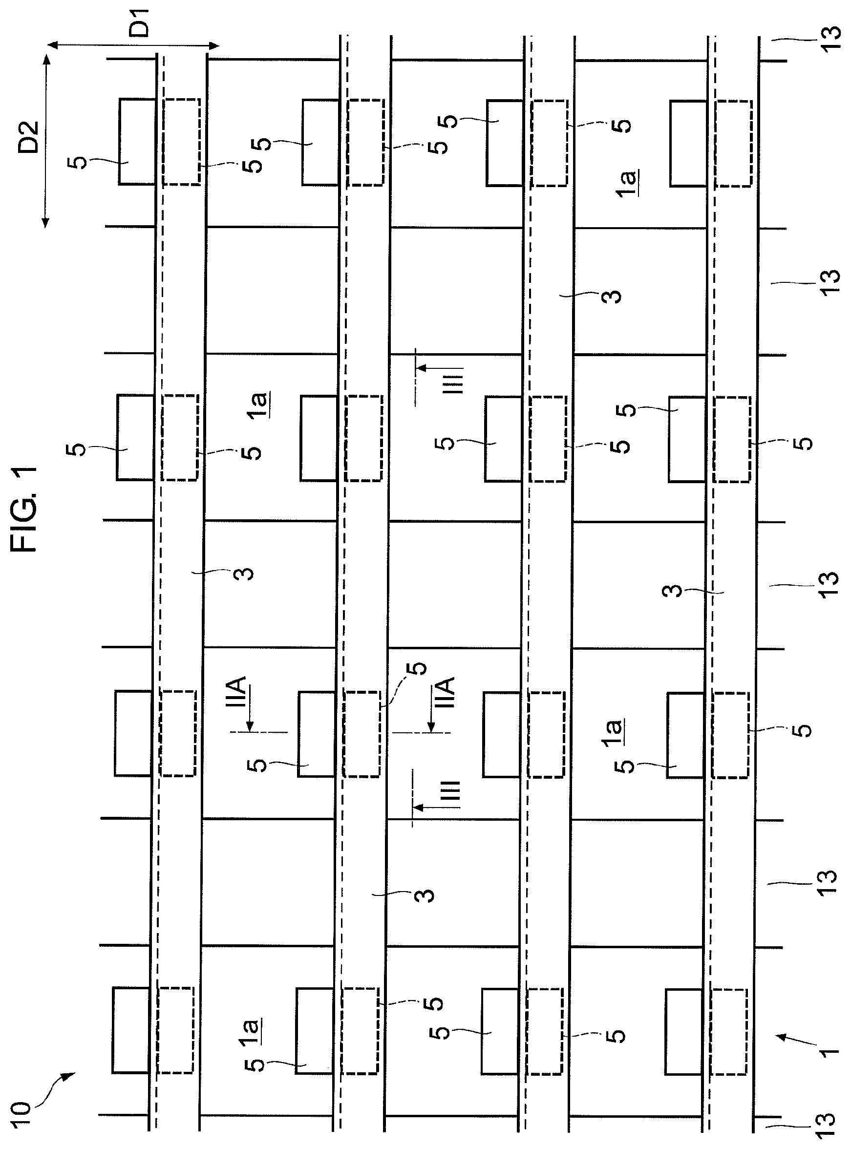
illustrates a joint structure according to a first embodiment of the present invention.
A is a view of the IIA-IIA arrows in .
B is a partially enlarged view of A .
is a view of the arrows in .
is a flowchart illustrating a method of assembling the joint structure according to the first embodiment of the present invention.
A is an illustration of the method of assembling the joint structure according to the first embodiment of the present invention.
B is another illustration of the method of assembling the joint structure according to the first embodiment of the present invention.
C is another illustration of the method of assembling the joint structure according to the first embodiment of the present invention.
A illustrates another configuration example of a connection member and a joint portion.
B illustrates still another configuration example of the connection member and the joint portion.
illustrates configurations of a connection member and a joint portion according to a reference example.
illustrates a joint structure according to a second embodiment of the present invention.
A is a view of the IXA-IXA arrows in .
B is a view of the IXB-IXB arrows in .
illustrates another configuration example of the connection member and the joint portion.
A illustrates another configuration example of the connection member and the joint portion.
B illustrates the connection member in A .
A is an illustration of a method of assembling a joint structure in the case of A .
B is another illustration of the method of assembling the joint structure in the case of A .
DESCRIPTION OF EMBODIMENTS
The following describes embodiments of the present invention with reference to the drawings. In the drawings, the common parts are denoted by the same reference signs, and overlapping description is omitted.
First Embodiment
Configuration of Joint Structure
illustrates a joint structure 10 according to a first embodiment of the present invention. A is a view of the IIA-IIA arrows in . is a view of the arrows in . The joint structure 10 includes a reinforced member 1 , a reinforcing member 3 , and a connection member 5 . In other words, the joint structure 10 is formed by coupling the reinforced member 1 and the reinforcing member 3 to each other via the connection member 5 . The reinforced member 1 , the reinforcing member 3 , and the connection member 5 may be made of fiber reinforced plastic, metal, or another material. In this case, the reinforced member 1 , the reinforcing member 3 , and the connection member 5 may be, but do not need to be, formed of the same materials.
The reinforced member 1 is a plate-shaped member in an example of the respective drawings. The plate-shaped reinforced member 1 includes an attachment surface 1 a to which the connection member 5 is attached. The attachment surface 1 a is a surface facing in a thickness direction of the plate-shaped reinforced member 1 . The attachment surface 1 a may be a flat surface, but is not limited to this, and may be a curved surface.
The reinforcing member 3 is coupled to the reinforced member 1 via the connection member 5 . illustrates the first direction D 1 and the second direction D 2 that are along the attachment surface 1 a and that are perpendicular to each other. In the example of , a plurality of the reinforcing members 3 are arranged at intervals in the first direction D 1 , and each of the reinforcing members 3 extend in an elongated shape in the second direction D 2 . Each of the reinforcing members 3 has a cross section that is on a plane perpendicular to the second direction D 2 and whose size and shape may be constant regardless of positions in the second direction D 2 . The shape of the cross section of the reinforcing member 3 is a shape of an inverted-L in the example of A , but is not limited to this. A joint portion 3 a of the reinforcing member 3 may be formed integrally with the reinforcing member 3 , as illustrated in A . Alternatively, the joint portion 3 a may be formed as another member separate from the reinforcing member 3 , and be then coupled to the reinforcing member 3 . This coupling may be made by an adhesive or welding, a bolt or the like, or a combination thereof.
The connection member 5 is provided between the reinforced member 1 and the reinforcing member 3 , and couples these two members to each other. According to the present embodiment, the two connection members 5 are arranged such that in a perpendicular direction (the first direction D 1 in the example of A ), the two connection members 5 face each other, and the joint portion 3 a is sandwiched between the two connection members 5 . The perpendicular direction is perpendicular to the joining direction D 3 (refer to A ) in which the reinforced member 1 and the reinforcing member 3 are joined to each other. In this case, assuming that the two connection members 5 forms one pair, a plurality of pairs of the connection members 5 may be arranged at a plurality of respective connection positions at each of which the reinforced member 1 and the reinforcing member 3 are coupled to each other, as illustrated in . The one pair of the connection members 5 may have configurations symmetrical to each other with respect to a plane that is parallel to the joining direction D 3 and that passes through a position between these two connection members 5 . The pairs of the connection members 5 may have the same configurations regardless of the connection positions. Each of the connection members 5 has a cross section that is on a plane perpendicular to the second direction D 2 and whose size and shape may be constant regardless of positions in the second direction D 2 .
It is assumed that a first perpendicular direction and a second perpendicular direction are each the above-described perpendicular direction (first direction D 1 ), and are opposite to each other. At each of the connection positions, a first coupling portion 5 a of the one connection member 5 of the one pair is positioned on a first-perpendicular-direction side (the right side in A ) of the joint portion 3 a and can receive a load applied from the joint portion 3 a to a first-perpendicular-direction side, and a first coupling portion 5 a of the other connection member 5 of the one pair is positioned on a second-perpendicular-direction side (the left side in A ) of the joint portion 3 a and can receive a load applied from the joint portion 3 a to a second-perpendicular-direction side.
The connection member 5 includes the first coupling portion 5 a and a second coupling portion 5 b that are coupled to one and the other of the reinforced member 1 and the reinforcing member 3 , respectively. The first coupling portion 5 a is coupled to the joint portion 3 a of the one (the reinforcing member 3 in the present embodiment) of the reinforced member 1 and the reinforcing member 3 by an adhesive or welding. The connection member 5 is made of a material enabling elastic deformation. In other words, the connection member 5 before being adhered or welded to the reinforcing member 3 is formed so as to be elastically deformable.
B is a partially enlarged view of A , and illustrates the joint portion 3 a and the first coupling portion 5 a . The joint portion 3 a and the first coupling portion 5 a are shaped so as to be caught by each other in the joining direction D 3 in which the reinforced member 1 and the reinforcing member 3 are joined to each other. According to the present embodiment, the first coupling portion 5 a is shaped so as to interpose a part (the below-described protrusion portion 7 ) of the joint portion 3 a between portions of the first coupling portion 5 a in the joining direction D 3 . In other words, the first coupling portion 5 a includes overlapping surfaces 12 a and 12 b that overlap, in the joining direction D 3 , with overlapping surfaces 11 a and 11 b constituting the above-mentioned part of the joint portion 3 a . This part is sandwiched between the overlapping surfaces 12 a and 12 b in the joining direction D 3 .
The joining direction D 3 may denote a direction from a leading end of the joint portion 3 a to the closest position of the reinforced member 1 , and may denote a direction opposite to this direction. The leading end of the joint portion 3 a is included in the joint portion 3 a and closest to the reinforced member 1 . The above-mentioned closest position of the reinforced member 1 is included in the reinforced member 1 and closest to the joint portion 3 a . In the example of , the joining direction D 3 is a direction perpendicular to the attachment surface 1 a . In the present embodiment, the overlapping surfaces 11 a , 11 b , 12 a , and 12 b each face in a direction (e.g., a direction making, with the joining direction D 3 , an angle larger than 0 degrees and equal to or smaller than 45 degrees) inclined from the joining direction D 3 .
The joint portion 3 a includes the protrusion portion 7 protruding in the perpendicular direction (the first direction D 1 in B ) perpendicular to the joining direction D 3 in which the reinforced member 1 and the reinforcing member 3 are joined to each other. In the present embodiment, the joint portion 3 a includes the two protrusion portions 7 protruding in the perpendicular directions opposite to each other. An adhesive 9 for adhering a surface 11 of the protrusion portion 7 to a surface 12 of the first coupling portion 5 a is provided between both the surfaces 11 and 12 that face each other. The surface 11 includes the above-described overlapping surfaces 11 a and 11 b . The surface 12 includes the above-described overlapping surfaces 12 a and 12 b . Instead of using the adhesive 9 , both the surfaces 11 and 12 may be welded to each other. In this case, the joint portion 3 a (reinforcing member 3 ) and the first coupling portion 5 a (connection member 5 ) may be formed of a thermoplastic resin, or a thermoplastic resin film for the welding may be used. A bolt or the like does not need to be used for coupling the joint portion 3 a and the connection member 5 to each other.
The second coupling portion 5 b may be coupled to the reinforced member 1 by, for example, an adhesive or welding (or a bolt and a nut, or a rivet, or both of an adhesive or welding and a bolt and a nut, or both of an adhesive or welding and a rivet), which is not illustrated in to . In the example of , a longitudinal member 13 as well as the reinforcing member 3 are coupled to the attachment surface 1 a . The longitudinal member 13 extends in the first direction D 1 . A plurality of the longitudinal members 13 are arranged at intervals in the second direction D 2 . Each of the longitudinal members 13 is arranged so as to pass in the first direction D 1 through a space between the attachment surface 1 a and the reinforcing member 3 , as illustrated in .
The above-described joint structure 10 may be a monocoque structure in one example. In this case, for example, the plate-shaped reinforced member 1 is an outer plate constituting a fuselage of an aircraft or constituting a body of an automobile. When the reinforced member 1 is an outer plate (skin) constituting a fuselage of an aircraft (e.g., a passenger aircraft), the above-described first direction D 1 is an axial direction parallel to a central axis of the fuselage of the aircraft, and the second direction D 2 is a circumferential direction around the central axis. Such an outer plate 1 may be formed in a cylindrical shape, for example. For such an outer plate 1 , each of the reinforcing members 3 is a frame extending in the circumferential direction, and the attachment surface 1 a is an inner circumferential surface extending in the first direction D 1 and in the second direction D 2 . Each of the longitudinal members 13 (stringers) is coupled to the outer plate 1 so as to extend in the axial direction. Although a plurality of pairs of the connection members 5 are provided in the above description, one pair of the connection members 5 may be provided instead of a plurality of pairs of the connection members 5 , depending on sizes and shapes of the reinforced member 1 and the reinforcing member 3 .
Method for Assembling Joint Structure
is a flowchart illustrating a method of assembling the above-described joint structure 10 . A to C are illustrations of the method of assembling the joint structure 10 .
At the step S 1 , the reinforced member 1 , the reinforcing member 3 , and the connection member 5 are prepared.
At the step S 2 , the first coupling portion 5 a of the connection member 5 is coupled to one (the reinforcing member 3 in the present embodiment) of the reinforced member 1 and the reinforcing member 3 , and the second coupling portion 5 b of the connection member 5 is coupled to the other (the reinforced member 1 in the present embodiment) of the reinforced member 1 and the reinforcing member 3 .
Here, the first coupling portion 5 a and the reinforcing member 3 may be coupled to each other as follows. In other words, the first coupling portion 5 a and the joint portion 3 a are arranged such that the first coupling portion 5 a and the joint portion 3 a are caught by each other in the joining direction D 3 (two directions D 3 opposite to each other). In this state, the first coupling portion 5 a and the joint portion 3 a are coupled to each other by an adhesive or welding. The step S 2 includes steps S 21 to S 23 .
At the step S 21 , the second coupling portion 5 b of each of the two connection members 5 is coupled to the attachment surface 1 a of the reinforced member 1 such that these two connection members 5 face each other in the perpendicular direction (first direction D 1 ) perpendicular to the joining direction D 3 , as illustrated in A . This coupling may be made by an adhesive or welding, for example, but there is no limitation to this.
The second coupling portions 5 b of the two connection members 5 are coupled to the attachment surface 1 a by the step S 21 . In this state, the two connection members 5 extend in the joining direction D 3 from the second coupling portions 5 b coupled to the attachment surface 1 a , so as to form a gap G in the first direction D 1 at the first coupling portions 5 a between these connection members 5 , as illustrated in A . The gap G includes an opening Go facing in the joining direction D 3 , on a side opposite to the attachment surface 1 a (opposite to the second coupling portions 5 b ). The gap G includes a reception portion Gr closer to the attachment surface 1 a (closer to the second coupling portions 5 b ) than the opening Go. A size of the reception portion Gr in the first direction D 1 is larger than a size of the opening Go in the first direction D 1 . The gap G may have a shape conforming to a shape of the joint portion 3 a . For example, the protrusion portions 7 are received in the reception portion Gr at the below-described step S 22 , and accordingly, the reception portion Gr has a shape conforming to shapes of the protrusion portions 7 . Such a gap G is defined by the surfaces 12 of the first coupling portions 5 a of the two connection members 5 . The gap G penetrates through the two connection members 5 in the second direction D 2 .
At the step S 22 , the two connection members 5 are elastically deformed so as to widen the opening Go, as illustrated in B . For example, the two connection members 5 may be elastically deformed so as to widen the opening Go, by human hands or by pushing the joint portion 3 a into the opening Go in the joining direction D 3 . Next, the protrusion portions 7 of the joint portion 3 a are inserted into the gap G from the opening Go in the joining direction D 3 . The protrusion portions 7 are thereby positioned in the reception portion Gr. As a result, the protrusion portions 7 are received in the reception portion Gr, and the joint portion 3 a and each of the first coupling portions 5 a are arranged so as to be caught by each other in the joining direction D 3 , as illustrated in C . In the example of C , each of the protrusion portions 7 of the first coupling portions 5 a of the respective connection members 5 is thereby brought into a state of being sandwiched, in the joining directions D 3 , between the overlapping surface 12 a and the overlapping surface 12 b of the first coupling portion 5 a of the corresponding connection member 5 , as illustrated in B .
As a result of the step S 22 , the reinforcing member 3 is supported by the reinforced member 1 via the joint portion 3 a and the connection member 5 , thus making a temporarily assembled state of the joint structure 10 . In other words, elastic force of the connection member 5 prevents the joint portion 3 a from being detached from the connection member 5 in any direction.
In the present embodiment, the joint portion 3 a has a size (a size in the first direction D 1 in the example of A ) that gradually increases in a region from its leading end on the side of the attachment surface 1 a to its intermediate portion as a position shifts to a side opposite to the attachment surface 1 a . Further, this size of the joint portion 3 a gradually decreases in a region from its intermediate portion (the portion at which the size becomes maximum) to a predetermined position as a position shifts to the side opposite to the attachment surface 1 a . This makes it easy to insert the joint portion 3 a into the gap G, from its leading end portion, through the opening Go.
When the joint portion 3 a and the first coupling portion 5 a are coupled by the adhesive 9 , the adhesive 9 may be applied to one or both of the surface 11 of the protrusion portion 7 and the surface 12 of the first coupling portion 5 a before the joint portion 3 a is inserted into the gap G at the step S 22 .
In this case, at the step S 23 , the adhesive 9 is cured to couple the first coupling portion 5 a and the joint portion 3 a to each other by the adhesive 9 . For example, in a state where the protrusion portion 7 is received in the reception portion Gr, the surface 11 and the surface 12 are connected via the adhesive 9 , and this state is thus maintained until the adhesive 9 is cured. At this time, the first coupling portions 5 a of the respective connection members 5 are pressed toward the joint portion 3 a by an appropriate means in the directions (first direction D 1 ) indicated by the arrows A in C . This pressing may be maintained until the adhesive 9 is cured, for example.
In the case where welding is performed instead of the coupling with the adhesive 9 , the first coupling portion 5 a and the joint portion 3 a may be coupled to each other by welding at the step S 23 when the joint portion 3 a (protrusion portion 7 ) and the connection member 5 (first coupling portion 5 a ) are formed of thermoplastic resins. At this time, the first coupling portion 5 a and the joint portion 3 a themselves may be melted and directly welded and coupled to each other, or both may be coupled to each other by welding with a thermoplastic resin film. When the thermoplastic resin film is used, the joint portion 3 a and the connection member 5 do not need to be formed of thermoplastic resins. In such a manner, the surface 11 of the protrusion portion 7 and the surface 12 of the first coupling portion 5 a may be coupled to each other by the welding.
In this case, in one example, the surface 11 of the protrusion portion 7 and the surface 12 of the first coupling portion 5 a are heated by a heater and thereby melted before the joint portion 3 a is inserted into the gap G at the step S 22 . In this state, the joint portion 3 a is inserted into the gap G. Then, at the step S 23 , the first coupling portions 5 a of the respective connection members 5 are kept pressed toward the joint portion 3 a by an appropriate means in the directions (first direction D 1 ) indicated by the arrows A in C so as to press the surface 12 against the surface 11 until the melted surface 11 and surface 12 are cooled and solidified and thereby integrated with each other. In another example, at the step S 23 , vibration welding may cause the protrusion portion 7 inserted into the gap G and the first coupling portion 5 a to be coupled to each other directly or via a thermoplastic resin film. Alternatively, at the step S 23 , another welding method may cause the surface 11 and the surface 12 to be integrated with each other directly or via a thermoplastic resin film so that the joint portion 3 a and the first coupling portion 5 a are coupled to each other. In the case where the thermoplastic resin film is used as described above, the thermoplastic resin film also can be regarded as the adhesive 9 , for example when the joint portion 3 a and the first coupling portion 5 a are made of a material (e.g., metal) that is not melted at the time of the welding.
Alternatively, at the step S 23 , the first coupling portions 5 a of the respective connection members 5 may be pressed toward the joint portion 3 a by an appropriate means while the respective first coupling portions 5 a and the joint portions 3 a are heated by an external heater or the like. Next, at the step S 23 , the heating may be stopped. Then, at the step S 23 , the pressing may be stopped once the adhesive 9 is cured, or once the portion melted for welding is solidified.
Assuming that the two connection members 5 form one pair, the above-described step S 2 may be performed for each pair of the connection members 5 when the reinforced member 1 and the one reinforcing member 3 are connected to each other by a plurality of the pairs of the connection members 5 as illustrated in . In this case, after the step S 21 is performed for a plurality of the pairs of the connection members 5 , the steps S 22 and S 23 may be performed simultaneously for a plurality of the pairs of the connection members 5 . Also when a plurality of the reinforcing members 3 are provided as illustrated in , each of the reinforcing members 3 may be coupled to the reinforced member 1 via a plurality of pairs of the connection members 5 as described above.
Other Configuration Examples of First Embodiment
In the first embodiment, shapes of the joint portion 3 a and the connection member 5 are not limited to the shapes illustrated in A and B . For example, the joint portion 3 a and the connection member 5 may have shapes illustrated in A or B . Each of A and B is a view of the IIA-IIA arrows in (i.e., corresponds to B ), but illustrates the case where the joint portion 3 a and the connection member 5 have other shapes.
The following describes the configuration example of A and the configuration example of B . The matters that are not described below for the joint structure 10 and the method of assembling the same in the case of these configuration examples may be the same as those described above.
In the example of A , the joint portion 3 a is provided with the two protrusion portions 7 that protrude in directions (first direction D 1 ) perpendicular to the joining direction D 3 and opposite to each other. One (on the right side in A ) of the two protrusion portions 7 includes an overlapping surface 11 b facing in the joining direction D 3 toward a side of the attachment surface 1 a , and includes an overlapping surface 11 a facing toward a side opposite to the attachment surface 1 a in a direction inclined from the joining direction D 3 . The other protrusion portion 7 includes an overlapping surface 11 a facing in the joining direction D 3 toward a side opposite to the attachment surface 1 a , and includes an overlapping surface 11 b facing toward a side of the attachment surface 1 a in a direction inclined from the joining direction D 3 .
The two connection members 5 provided for such a joint portion 3 a have the following shapes. The surface 12 of one of the connection members 5 includes surfaces 12 a and 12 b facing, and coupled to, the overlapping surfaces 11 a and 11 b of the one protrusion portion 7 , respectively. The surface 12 of the other connection member 5 includes surfaces 12 a and 12 b facing, and coupled to, the overlapping surfaces 11 a and 11 b of the other protrusion portion 7 , respectively
In the example of B , the joint portion 3 a is provided with the two protrusion portions 7 that protrude in directions (first direction D 1 ) perpendicular to the joining direction D 3 and opposite to each other. Each of the two protrusion portions 7 includes an overlapping surface 11 b facing toward a side of the attachment surface 1 a in a direction inclined from the joining direction D 3 , and includes an overlapping surface 11 a facing in the joining direction D 3 toward a side opposite to the attachment surface 1 a . Each of the two connection members 5 provided for such a joint portion 3 a includes surfaces 12 a and 12 b facing, and coupled to, the overlapping surfaces 11 a and 11 b of the corresponding protrusion portion 7 , respectively.
Advantageous Effects of First Embodiment
According to the first embodiment, the joint portion 3 a of the reinforcing member 3 and the connection member 5 are coupled to each other by the adhesive 9 or welding, and the joint portion 3 a and the first coupling portion 5 a of the connection member 5 are shaped so as to be caught by each other in the joining direction D 3 . Thus, the joint portion 3 a and the connection member 5 are coupled to each other by the adhesive 9 or welding and further caught by each other in the joining direction D 3 so that mechanical strength of the coupled portion between the joint portion 3 a and the connection member 5 can be secured in the joining direction D 3 . Accordingly, a bolt or the like does not need to be used for coupling the joint portion 3 a and the connection member 5 to each other. Thus, a hole thorough which a bolt or the like penetrates does not need to be formed in the joint portion 3 a and the connection member 5 , the number of components of the joint structure 10 is decreased, and a work load of assembling the joint structure 10 is reduced.
Meanwhile, illustrates a configuration of a reference example, and corresponds to A . In , a connection member 105 that connects a reinforced member 101 and a reinforcing member 103 to each other is coupled to a joint portion 103 a of the reinforcing member 103 by an adhesive 109 . However, the adhesive 109 alone achieves insufficient mechanical strength in the joining direction D 3 , for a coupled portion between the joint portion 103 a and the connection member 105 . For this reason, the joint portion 103 a and the connection member 105 are connected to each other further by a bolt 111 and a nut 112 . In this case, differently from the first embodiment of the present invention, a hole through which the bolt 111 penetrates needs to be formed in the joint portion 103 a and the connection member 105 . In contrast, according to the joint structure 10 of the first embodiment, such a hole for a bolt does not need to be formed as described above. Such an advantageous effect can be gained against the case where, instead of the bolt 111 and the nut 112 , rivet coupling is used in in order to achieve mechanical strength, which is not illustrated in the drawing.
Further, according to the first embodiment, each of the connection members 5 is elastically deformable. Thus, the connection member 5 is inserted into the gap G while elastically deformed as in the above-described step S 22 . Thereby, temporary assembling of the joint structure 10 can be easily made.
Second Embodiment
illustrates a joint structure 10 according to a second embodiment of the present invention. A is a view of the IXA-IXA arrows in . B is a view of the IXB-IXB arrows in . The following describes the second embodiment, but configurations of the joint structure 10 of the second embodiment and a method of assembling the same that are not described below may be the same as those in the first embodiment.
In the second embodiment, the reinforced member 1 and the reinforcing member 3 are connected to each other at each of a plurality of connection positions by the one connection member 5 instead of a plurality of the connection members 5 . Hereinafter, two directions (first direction D 1 ) perpendicular to the joining direction D 3 and opposite to each other are assumed to be a first perpendicular direction (a right direction in A and B ) and a second perpendicular direction (a left direction A and B ).
At one of the connection positions, the first coupling portion 5 a of the connection member 5 is positioned on a first-perpendicular-direction side of the joint portion 3 a , and can receive a first-perpendicular-direction load from the joint portion 3 a , as illustrated in A . At this connection position, the first coupling portion 5 a and the joint portion 3 a are coupled to each other in the first perpendicular direction by an adhesive 9 or welding. The adhesive 9 is provided between both of these as illustrated in A .
At another connection position, the first coupling portion 5 a of the connection member 5 is positioned on a second-perpendicular-direction side of the joint portion 3 a , and can receive a second-perpendicular-direction load from the joint portion 3 a , as illustrated in B . At this connection position, the first coupling portion 5 a and the joint portion 3 a are coupled to each other in the second perpendicular direction by an adhesive 9 or welding. The adhesive 9 is provided between both of these as illustrated in B .
In the example of , a plurality of the connection members 5 are arranged in a zigzag manner at each of the reinforcing members 3 extending in an elongated shape in the second direction D 2 . In other words, at each of the reinforcing members 3 , for each combination of the two connection members 5 adjacent to each other in the second direction D 2 , the one connection member 5 is positioned on the first-perpendicular-direction side of the joint portion 3 a , and the other connection member 5 is positioned on the second-perpendicular-direction side of the joint portion 3 a . In this case, configurations (the joint portion 3 a , the connection member 5 , the adhesive 9 , and the like) concerning each connection position may be the same as those in the case of A or B . In other words, a plurality of the connection members 5 positioned on the first-perpendicular-direction side of the joint portion 3 a and a plurality of the connection members 5 positioned on the second-perpendicular-direction side of the joint portion 3 a are arranged in the zigzag manner when viewed in the joining direction D 3 (the direction perpendicular to the paper sheet of ).
In the method of assembling the joint structure 10 according to the second embodiment, the steps S 21 to S 23 of the above-described step S 2 are performed as follows.
At the step S 21 , for the one reinforcing member 3 , the second coupling portion 5 b of the one connection member 5 is coupled to the one attachment surface 1 a at each of the connection positions that are different from each other in the second direction D 2 . At this time, these connection members 5 are arranged in the zigzag manner as described above.
At the step S 22 , the one reinforcing member 3 is arranged such that this reinforcing member 3 (joint portion 3 a ) is sandwiched in the first direction D 1 between the connection members 5 provided at the different connection positions, and the joint portion 3 a and the first coupling portion 5 a are caught by each other in the joining direction D 3 at each of the connection positions, as illustrated in A and B .
At the step S 23 , in the state of the arrangement made at the step S 22 , the first coupling portion 5 a and the joint portion 3 a are coupled by the adhesive 9 or welding at each of the connection positions.
According to the second embodiment, each of the reinforcing members 3 is sandwiched in the first direction D 1 between the connection members 5 provided at the connection positions that are different from each other in the second direction D 2 . Accordingly, the reinforcing member 3 is prevented from being displaced from the connection members 5 in each of the first perpendicular direction and the second perpendicular direction, thus maintaining a state where the joint portion 3 a and the first coupling portion 5 a are caught by each other in the joining direction D 3 . Therefore, the same advantageous effect as that of the first embodiment can be gained while the number of connection members 5 are made smaller than that in the case of the first embodiment. Thus, the configuration of the first embodiment or the second embodiment can be adopted depending on mechanical strength intended for the joint structure 10 .
In the second embodiment, the connection members 5 (that are provided at the different connection positions and that interpose the reinforcing member 3 between themselves in the first direction D 1 ) and the joint portion 3 a may be same as the one connection member 5 , the other connection member 5 , and the joint portion 3 a in A or B , respectively, or may have other shapes.
The present invention is not limited to the above-described embodiments. As a matter of course, various modifications can be made within the scope of the technical idea of the present invention. For example, any one of the following modified examples 1 to 3 may be adopted, or two or more of the modified examples 1 to 3 may be arbitrarily combined to be adopted. In this case, the matters that are not described below may be the same as those described above.
Modified Example 1
According to the modified example 1, the joint portion 3 a may be shaped so as to interpose, between portions of the joint portion 3 a , a part of each of the first coupling portions 5 a in the joining direction D 3 as illustrated in . is a view of the IIA-IIA arrows in , but illustrates a configuration example where the joint portion 3 a and the connection member 5 have other shapes. When these shapes are applied to the first embodiment or the second embodiment described above, the other configurations of the joint structure 10 and the method of assembling this joint structure 10 may be the same as those described above.
Modified Example 2
According to the modified example 2, in the case where the reinforcement member 1 is not flat, or in another appropriate case, a joint portion having the same configuration as that of the above-described joint portion 3 a may be provided at the reinforced member 1 , instead of providing the joint portion 3 a at the reinforcing member 3 . In this case, the first coupling portion 5 a of the connection member 5 is coupled to the joint portion of the reinforced member 1 , and the second coupling portion 5 b of the connection member 5 is coupled to the reinforcing member 3 . Here, the first coupling portion 5 a and the joint portion of the reinforced member 1 are coupled to each other by the same configurations as those by which the first coupling portion 5 a and the joint portion 3 a described above are coupled to each other. Further, the second coupling portion 5 b and the reinforcing member 3 may be coupled to each other by an adhesive or welding (or a bolt and a nut, or a rivet, or a combination of an adhesive or welding and a bolt and a nut, or both of an adhesive or welding and a rivet).
Modified Example 3
According to the modified example 3, the second coupling portion 5 b of the connection member 5 is coupled to a joint portion 1 b of the reinforced member 1 by an adhesive 9 or welding as illustrated in A , and the second coupling portion 5 b and the joint portion 1 b may be shaped so as to be caught by each other in the joining direction D 3 in which the reinforced member 1 and the reinforcing member 3 are joined to each other. A is a view of the IIA-IIA arrows in , but illustrates a configuration example where the second coupling portion 5 b of the connection member 5 is coupled to the reinforced member 1 in such a manner. In the example of A , the connection member 5 includes the two first coupling portions 5 a , the two second coupling portions 5 b , and an intermediate portion 5 c.
The two first coupling portions 5 a are arranged such that in a direction (first direction D 1 ) perpendicular to the joining direction D 3 , the two first coupling portions 5 a face each other, and the joint portion 3 a of the reinforcing member 3 is sandwiched between the two first coupling portions 5 a . The two first coupling portions 5 a each have the same configuration (a shape, a material, and the like) and function as those of the two first coupling portions 5 a in the one pair of the connection members 5 in the first embodiment. Accordingly, their detailed description is omitted. In A , the joint portion 3 a of the reinforcing member 3 is the same as the joint portion 3 a in the first embodiment.
The two second coupling portions 5 b are arranged such that in the direction (first direction D 1 ) perpendicular to the joining direction D 3 , the two second coupling portions 5 b face each other, and the joint portion 1 b of the reinforced member 1 is sandwiched between the two second coupling portions 5 b . The joint portion 1 b may be formed integrally with the reinforced member 1 . Alternatively, the joint portion 1 b may be formed as a member separate from the reinforced member 1 , and may be then coupled to the reinforced member 1 . This coupling may be made by an adhesive or welding, a bolt or the like, or a combination thereof.
The two second coupling portions 5 b and the joint portion 1 b in the modified example 3 may have the same functions (e.g., the same configuration (shape and material)) as those of the two first coupling portions 5 a and the joint portion 3 a in the modified example 3. For example, the joint portion 1 b may include the protrusion portions 7 that are caught by the respective second coupling portions 5 b in the joining direction D 3 .
The intermediate portion 5 c is positioned between the two first coupling portions 5 a and the two second coupling portions 5 b , and is coupled to the two first coupling portions 5 a and the two second coupling portions 5 b . For example, the intermediate portion 5 c , the respective first coupling portions 5 a , and the respective second coupling portions 5 b may be formed integrally with each other.
B is a diagram of A in which illustrations of the configurations other than that of the connection member 5 are omitted. As illustrated in B , the connection member 5 forms a gap G in the first direction D 1 between the two first coupling portions 5 a , and also forms a gap G in the first direction D 1 between the two second coupling portions 5 b . Each of the gaps G includes an opening Go at an end in the joining direction D 3 and a reception portion Gr on a side closer to the intermediate portion 5 c than the opening Go. The opening Go and the reception portion Gr have configurations (shapes, sizes, and the like) and functions that are the same as those of the opening Go and the reception portion Gr in the case of the first embodiment.
A and B are views corresponding to A , and illustrate one example of the method of assembling the joint structure 10 according to the modified example 3. In the method of assembling the joint structure 10 according to the modified example 3, the above-described step S 2 may be performed as follows.
At the step S 2 in the above-described assembling method, the connection member 5 is elastically deformed so as to widen the opening Go of the gap G that is formed by the two second coupling portions 5 b , as illustrated in A . Next, the connection member 5 is attached to the joint portion 1 b such that the joint portion 1 b (protrusion portions 7 ) passes through this opening Go and is thus arranged in the reception portion Gr. Then, the connection member 5 is elastically deformed so as to widen the opening Go of the gap G that is formed by the two first coupling portions 5 a , as illustrated in B . Next, the joint portion 3 a is attached to the connection member 5 such that the joint portion 3 a (protrusion portions 7 ) passes through this opening Go and is thus arranged in the reception portion Gr. Then, the first coupling portion 5 a and the joint portion 3 a are coupled to each other by an adhesive 9 or welding, and the second coupling portion 5 b and the joint portion 1 b are coupled to each other by an adhesive 9 or welding.
Here, a timing of applying the adhesive 9 , a timing of heating and pressing each portion for welding, and the like may be the same as those in the case of first embodiment described above, or may be appropriately changed. After the connection member 5 is attached to the joint portion 3 a of the reinforcing member 3 , the joint portion 1 b of the reinforced member 1 may be attached to the connection member 5 . In this case, other matters may be the same as those described above. The reinforced member 1 and the reinforcing member 3 may be coupled by the connection member 5 at one connection position or at each of a plurality of connection positions as in the first embodiment.
REFERENCE SIGNS LIST
•
• 1 reinforced member (outer plate), 1 a attachment surface, 1 b joint portion, 3 reinforcing member (frame), 3 a joint portion, 5 connection member, 5 a first coupling portion, 5 b second coupling portion, 5 c intermediate portion, 7 protrusion portion, 9 adhesive, 10 joint structure, 11 surface of joint portion, 11 a and 11 b overlapping surface, 12 a and 12 b overlapping surface, 13 longitudinal member, G gap, D 1 first direction, D 2 second direction, D 3 joining direction
Figures (12)
Citations
This patent cites (24)
- US3703747
- US4671470
- US6374570
- US6945727
- US7555873
- US7670527
- US8840979
- US8844868
- US9862477
- US2004/0011927
- US2007/0166098
- US2008/0230652
- US2013/0164465
- US2014/0272312
- US2016/0244140
- US1190056
- US48-113546
- US2004-507629
- US2007-534538
- US2008-222221
- US2015-072042
- US2006139669
- US2578085
- USWO-2005/098241