Abstract
A vehicle includes an upper frame, a lower frame, a front frame, a rear frame, a pair of rear wheels, a drive motor to drive the pair of rear wheels, a battery supported by the upper frame and the lower frame to supply electric power to the drive motor, a straddled seat at a higher position than the drive motor, and a bar handle at a higher position than the straddled seat. The battery includes a battery lower portion and a battery upper portion. The battery upper portion includes a projection that overhangs in at least a horizontal direction with respect to the battery lower portion. At least a portion of the drive motor is below or directly below the projection.
Claims (12)
1. A vehicle comprising: an upper frame; a lower frame; a front frame connecting a front portion of the upper frame with the lower frame; a rear frame connecting a rear portion of the upper frame with a rear portion of the lower frame; a pair of rear wheels; a drive motor to drive the pair of rear wheels; and a battery supported by the upper frame and the lower frame to supply electric power to the drive motor; wherein the battery includes a battery lower portion and a battery upper portion above the battery lower portion; the battery upper portion includes a projection that overhangs in at least a horizontal direction with respect to the battery lower portion; and at least a portion of the drive motor is below the projection.
Show 11 dependent claims
2. The vehicle according to claim 1 , wherein a length of the battery upper portion is greater than a length of the battery lower portion in a side view of the vehicle.
3. The vehicle according to claim 1 , wherein an area of a cross section of the battery upper portion is greater than an area of a cross section of the battery lower portion in the horizontal direction.
4. The vehicle according to claim 1 , wherein the projection overhangs rearward with respect to the battery lower portion.
5. The vehicle according to claim 1 , wherein the battery includes a battery case that includes the projection.
6. The vehicle according to claim 1 , wherein the battery upper portion projects forward with respect to the battery lower portion and corresponds to a shape of the front frame.
7. The vehicle according to claim 1 , wherein the battery upper portion overhangs forward and rearward with respect to the battery lower portion.
8. The vehicle according to claim 1 , wherein a lateral width of the battery upper portion is equal or substantially equal to a lateral width of the battery lower portion.
9. The vehicle according to claim 1 , further comprising a charging/discharging connector in the battery upper portion that does not protrude from a front end or a rear end of the battery upper portion.
10. The vehicle according to claim 9 , wherein the battery upper portion further includes a slanted portion including the charging/discharging connector.
11. The vehicle according to claim 1 , further comprising an elastic member between the battery and at least one of the upper frame and the lower frame.
12. The vehicle according to claim 1 , further comprising: a straddled seat at a higher position than the drive motor; and a bar handle is at a higher position than the straddled seat.
Full Description
Show full text →
CROSS REFERENCE TO RELATED APPLICATIONS
This application claims the benefit of priority to Japanese Patent Application No. 2021-207429 filed on Dec. 21, 2021. The entire contents of this application are hereby incorporated herein by reference.
BACKGROUND OF THE INVENTION
1. Field of the Invention
The present invention relates to vehicles, and more specifically to electric ATVs (All Terrain Vehicles) and the like.
2. Description of the Related Art
Japanese Patent No. 5509811 discloses an electric rough terrain vehicle which is pertinent to conventional techniques of this kind. The vehicle includes a steering shaft which is supported pivotably at a front portion of a vehicle frame; a left-right pair of front wheels steered by means of the steering shaft; a left-right pair of rear wheels; a left-right pair of electric motors disposed between the left and right front wheels for driving the left and right front wheels respectively; a left-right pair of electric motors disposed between the left and right rear wheels for driving the left and right rear wheels respectively; and a rectangular parallelepiped battery disposed between the front and the rear wheels.
Also, Japanese Patent No. 4214759 discloses a four-wheeled electric rough terrain vehicle. The vehicle includes an electric motor disposed at a position near a rear portion of a body frame; a plurality of rectangular parallelepiped batteries provided in line in a fore-aft direction at a generally intermediate portion of the body frame; and a controller disposed ahead of the batteries.
As shown in Japanese Patent No. 5509811 and Japanese Patent No. 4214759, batteries which are used in the electric ATV occupy a large volume in the vehicle body, and therefore layout of the battery and other components must be ingeniously designed.
However, in both of Japanese Patent No. 5509811 and Japanese Patent No. 4214759, the battery is formed in a rectangular parallelepiped shape, and the battery and the electric motor are apart from each other. In other words, there is room for consideration of a layout of the battery and the electric motor within a limited space while allowing for an increased volume of the battery.
SUMMARY OF THE INVENTION
Preferred embodiments of the present invention provide vehicles that each allow a satisfactory layout of the battery and the drive motor within a limited space and an increased volume of the battery.
According to a preferred embodiment of the present invention, a vehicle includes an upper frame, a lower frame, a front frame connecting a front portion of the upper frame with the lower frame, a rear frame connecting a rear portion of the upper frame with a rear portion of the lower frame, a pair of rear wheels, a drive motor to drive the pair of rear wheels, and a battery supported by the upper frame and the lower frame to supply electric power to the drive motor. In this vehicle, the battery includes a battery lower portion and a battery upper portion above the battery lower portion, the battery upper portion includes a projection that overhangs in at least a horizontal direction with respect to the battery lower portion, and at least a portion of the drive motor is below the projection.
In a preferred embodiment of the present invention, the battery upper portion includes a projection that overhangs at least in a horizontal direction with respect to the battery lower portion, and at least a portion of the drive motor is below or directly below the projection. By ingeniously designing the shape of the battery in this way, it becomes possible to make effective use of the space below the projection, position the drive motor closely to the battery, i.e., to lay out the battery and the drive motor satisfactorily within a limited space while also providing an increased battery volume.
Preferably, in a side view of the vehicle, a length of the battery upper portion is greater than a length of the battery lower portion. In this case, it is possible to easily provide the projection, and make effective use of the space below the projection.
Further preferably, in a horizontal direction, an area of a cross section of the battery upper portion is greater than an area of a cross section of the battery lower portion. In this case, it is possible to easily provide the projection, and make effective use of the space below the projection.
Further, preferably, the projection overhangs rearward with respect to the battery lower portion. In this case, it is possible to position the drive motor behind the battery. In other words, it is possible to position the battery in a vacant space forward of the drive motor, thus making effective use of the limited space.
Preferably, the battery includes a battery case including the projection. With this arrangement, even in a case where the battery includes a battery case, it is possible to easily provide the projection, and make effective use of the space below the projection.
Further preferably, the battery upper portion projects forward with respect to the battery lower portion and corresponds to a shape of the front frame. In this case, it is possible to position the battery satisfactorily in the space defined by the front frame.
Further, preferably, the battery upper portion projection overhangs forward and rearward with respect to the battery lower portion. In this case, even in a case where the region which is surrounded by the upper frame, the lower frame, the front frame, and the rear frame is narrower in its lower portion than its upper portion in a side view of the vehicle, it is possible to position the battery and the drive motor satisfactorily within the region.
Preferably, a lateral width of the battery upper portion is equal or substantially equal to a lateral width of the battery lower portion. In this case, it is possible to provide a battery with a larger volume even if the space is limited.
Further preferably, the vehicle further includes a charging/discharging connector provided in the battery upper portion that does not protrude from a front end and a rear end of the battery upper portion. In this case, when the battery is removed from the vehicle, it is possible to easily remove the battery without causing the charging/discharging connector to be caught by the front frame or the rear frame.
Further, preferably, the battery upper portion further includes a slanted portion including the charging/discharging connector. In this case, it is possible to provide the charging/discharging connector so as not to protrude very much from the sides of the battery.
Preferably, the vehicle further includes an elastic member between the battery and at least one of the upper frame and the lower frame. In this case, it is possible for the elastic member to reduce impacts and vibrations to the battery when the vehicle is running.
Further preferably, the vehicle further includes a straddled seat at a higher position than the drive motor, and a bar handle is at a higher position than the straddled seat. Thus, the straddled seat and the bar handle are suitably applied to an ATV which is configured as above.
The above and other elements, features, steps, characteristics and advantages of the present invention will become more apparent from the following detailed description of the preferred embodiments with reference to the attached drawings.
BRIEF DESCRIPTION OF THE DRAWINGS
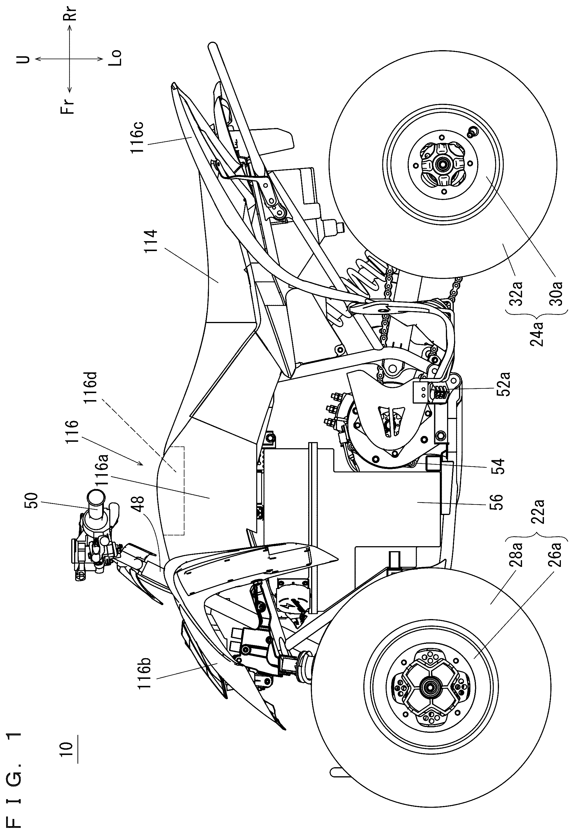
is a side view which shows a vehicle according to a preferred embodiment of the present invention.
is a plan view which shows the vehicle in .
is a perspective view which shows the vehicle with exterior components removed.
is a front view which shows the vehicle in .
is a side view which shows the vehicle in viewed from the left.
is a side view which shows the vehicle in viewed from the right.
is a plan view which shows the vehicle in .
is a bottom view which shows the vehicle in .
A to 9 C show a battery, wherein A is a plan view, B is a front view, and C is a side view.
is an illustrative sectional view taken along line A-A in .
is an illustrative sectional view taken along line B-B in .
is an illustrative sectional view taken along the line A-A which shows a vicinity of a battery lower portion.
is an enlarged perspective view which shows a vicinity of a battery upper portion.
is an illustrative sectional view taken along the line A-A which shows a vicinity of the battery upper portion.
A and 15 B show a variation of the battery, wherein A is an illustrative front view, and B is an illustrative side view.
A and 16 B show another variation of the battery, wherein A is an illustrative front view, and B is an illustrative side view.
A and 17 B show still another variation of the battery, wherein A is an illustrative front view, and B is an illustrative side view.
A and 18 B show still another variation of the battery, wherein A is an illustrative front view, and B is an illustrative side view.
A and 19 B show another variation of the battery, wherein A is an illustrative front view, and B is an illustrative side view.
A and 20 B show another variation of the battery, wherein A is an illustrative front view, and B is an illustrative side view.
A and 21 B show still another variation of the battery, wherein A is an illustrative front view, and B is an illustrative side view.
A and 22 B show still another variation of the battery, wherein A is an illustrative front view, and B is an illustrative side view.
DETAILED DESCRIPTION OF THE PREFERRED EMBODIMENTS
Hereinafter, preferred embodiments of the present invention will be described with reference to the drawings. It should be noted here that the terms front and rear, left and right, and up and down used in the preferred embodiments of the present invention refer to front and rear, left and right, and up and down based on the state where a driver of the vehicle 10 is seated in a straddled seat 114 (which will be described below), facing a bar handle 50 (which will be described below). In the drawings, “Fr” indicates forward, “Rr” indicates rearward, “R” indicates rightward, “L” indicates leftward, “U” indicates upward and “Lo” indicates downward.
Referring to and , a vehicle 10 according to a preferred embodiment of the present invention is an electric ATV which carries one person.
Referring to through , the vehicle 10 includes a body frame 12 . The body frame 12 includes a pair of upper frames 14 a , 14 b , a pair of lower frames 16 a , 16 b , a front frame 18 , and a rear frame 20 .
The pair of upper frames 14 a , 14 b extend in a fore-aft direction at a distance from each other in a left-right direction, with their intermediate portions having an inverted V-shape in a side view so as to slightly protrude upward. The pair of upper frames 14 a , 14 b have their generally intermediate portions connected by a support frame 14 c which supports a steering shaft 48 (which will be described below). The support frame 14 c is generally V-shaped, and is provided on the pair of upper frames 14 a , 14 b to extend forward and diagonally upward in a side view.
The pair of lower frames 16 a , 16 b extend in a fore-aft direction below the pair of upper frames 14 a , 14 b , at a distance from each other in a left-right direction, such that the distance between the pair is greater between rearward portions than between forward portions.
The front frame 18 connects front portions of the pair of upper frames 14 a , 14 b to the pair of lower frames 16 a , 16 b . More specifically, the front frame 18 includes a pair of first frames 18 a , 18 b which connect the front portions of the pair of upper frames 14 a , 14 b with front portions of the pair of lower frames 16 a , 16 b ; and a pair of second frames 18 c , 18 d which connect the front portions of the pair of upper frames 14 a , 14 b with generally intermediate portions of the pair of lower frames 16 a , 16 b . The pair of second frames 18 c , 18 d function as reinforcing members.
The rear frame 20 connects rear portions of the pair of upper frames 14 a , 14 b to rear portions of the pair of lower frames 16 a , 16 b . More specifically, the rear frame 20 includes a third frame 20 a which is generally U-shaped in a rear view and generally V-shaped in a side view and connects the rear portions of the pair of upper frames 14 a , 14 b to the rear portions of the pair of lower frames 16 a , 16 b ; a cross member 20 b which connects two end portions of the third frame 20 a ; a pair of fourth frames 20 c , 20 d which extend rearward and slightly upward from upper portions of both sides of the third frame 20 a ; a pair of fifth frames 20 e , 20 f which extend rearward and upward from generally intermediate portions of both sides of the third frame 20 a ; and a sixth frame 20 g which is generally U-shaped. The sixth frame 20 g is located so that its first end portion is sandwiched by a rear end portion of the fourth frame 20 c and a rear end portion of the fifth frame 20 e while its second end portion is sandwiched by a rear end portion of the fourth frame 20 d and a rear end portion of the fifth frame 20 f.
A pair of front wheels 22 a , 22 b are provided near a front portion of the body frame 12 and a pair of rear wheels 24 a , 24 b are provided near a rear portion of the body frame 12 (see and ). The front wheels 22 a , 22 b include wheels 26 a , 26 b and tires 28 a , 28 b assembled to the wheels 26 a , 26 b , respectively. Likewise, the rear wheels 24 a , 24 b include wheels 30 a , 30 b and tires 32 a , 32 b assembled to the wheels 30 a , 30 b , respectively.
The pair of front wheels 22 a , 22 b are connected to the body frame 12 via suspensions 34 a , 34 b , respectively.
The pair of rear wheels 24 a , 24 b are connected to the body frame 12 via a suspension 36 , swing arms 38 a , 38 b and so on. In other words, two side portions of the third frame 20 a of the rear frame 20 are connected with each other via a pivot shaft 40 which extends in a widthwise direction of the vehicle. The rear wheels 24 a , 24 b are connected with each other via an axle 42 which extends widthwise of the vehicle. At an intermediate portion of the axle 42 , an arm support portion 44 is attached rotatably with respect to the axle 42 . The pivot shaft 40 and the arm support portion 44 are connected with each other by the swing arms 38 a , 38 b extending in a fore-aft direction at a space in a left-right direction from each other. The swing arms 38 a , 38 b have their rear portions connected with each other by a connecting portion 46 . The suspension 36 is provided at an intermediate portion in the vehicle's widthwise direction, and connects the third frame 20 a with the connecting portion 46 .
A steering shaft 48 is provided to extend through a space between the pair of upper frames 14 a , 14 b . The steering shaft 48 has its lower end portion connected with the pair of first frames 18 a , 18 b of the front frame 18 . The steering shaft 48 is supported, at a position slightly above its intermediate portion, by the support frame 14 c . A bar handle 50 to steer the pair of front wheels 22 a , 22 b is attached to an upper end portion of the steering shaft 48 . The bar handle 50 is provided at a higher position than the straddled seat 114 . When the bar handle 50 is operated, the steering shaft 48 is rotated to steer the front wheels 22 a , 22 b via an unillustrated pair of tie rods.
A pair of steps 52 a , 52 b are attached to two end portions of the third frame 20 a of the rear frame 20 to extend outward of the vehicle.
The body frame 12 supports a drive motor 54 which drives the pair of rear wheels 24 a , 24 b , and a battery 56 which supplies electric power to the drive motor 54 . The drive motor 54 and the battery 56 are located on the pair of lower frames 16 a , 16 b . The drive motor 54 is behind the battery 56 . Preferably, the battery 56 is an interchangeable rechargeable battery.
Referring to A to 9 C , the battery 56 includes a battery case 56 a . The battery case 56 a includes projections 56 b , 56 c that extend outward and overhang in horizontal directions. The battery case 56 a houses a battery module 56 d (see ).
The battery 56 includes a battery lower portion 56 e and a battery upper portion 56 f provided on and above the battery lower portion 56 e . On a front surface of the battery lower portion 56 e , at its generally intermediate region, a protruding portion 56 g is provided. On an upper surface of the battery upper portion 56 f , a protruding portion 56 h is provided. The battery upper portion 56 f includes the projection 56 b overhanging farther forward than the battery lower portion 56 e , and the projection 56 c overhanging farther rearward than the battery lower portion 56 e . As described, the battery upper portion 56 f overhangs forward and rearward with respect to the battery lower portion 56 e . The battery upper portion 56 f and the battery lower portion 56 e look like a letter T in a side view. Also, the battery upper portion 56 f has a shape that corresponds or follows a shape of the pair of second frames 18 c , 18 d of the front frame 18 (see ). At least a portion of the drive motor 54 is below the projection 56 c , preferably directly below the projection 56 c . In other words, at least a portion of the drive motor 54 overlaps the projection 56 c in a plan view.
In a side view, the battery upper portion 56 f has a length L 1 which is greater than a length L 2 of the battery lower portion 56 e . Also, in a horizontal direction, the battery upper portion 56 f has an area of cross section which is greater than an area of cross section of the battery lower portion 56 e . The battery upper portion 56 f has a lateral width W 1 which is equal or substantially equal to a lateral width W 2 of the battery lower portion 56 e.
The battery upper portion 56 f includes slanted portions 56 i , 56 j in its front two corners. More specifically, the projection 56 b includes the slanted portions 56 i , 56 j in its two corners. The slanted portions 56 i , 56 j are provided with charging/discharging connectors 56 k , 56 l , respectively. The charging/discharging connectors 56 k , 56 l are provided in the battery upper portion 56 f such that it does not protrude from a front end and a rear end of the battery upper portion 56 f.
Referring to , and , in a side view, the drive motor 54 and the battery 56 are located in a region which is surrounded by the upper frames 14 a , 14 b , the lower frames 16 a , 16 b , the pair of second frames 18 c , 18 d of the front frame 18 , and the third frame 20 a of the rear frame 20 . In the present preferred embodiment, the drive motor 54 and the battery 56 are located inside the region which is surrounded by the upper frames 14 a , 14 b , the lower frames 16 a , 16 b , the second frames 18 c , 18 d of the front frame 18 , and the third frame 20 a of the rear frame 20 , and do not overlap these frames in a side view. An output shaft 54 a of the drive motor 54 is able to be positioned rearward and downward in the region. In a side view, the drive motor 54 and the battery 56 do not protrude downward from the pair of lower frames 16 a , 16 b.
The battery 56 is supported by the upper frames 14 a , 14 b and the lower frames 16 a , 16 b . More specifically, the battery 56 is supported as described below.
Referring to , , and through , the pair of second frames 18 c , 18 d of the front frame 18 are connected with each other by a rectangular pipe 58 extending in the vehicle's width direction. The rectangular pipe 58 includes a flange portion 58 a in its first end region (left end region), and a flange portion 58 b in its second end region (right end region). The flange portion 58 b of the rectangular pipe 58 includes a bracket 60 attached thereto with two fasteners 62 . The bracket 60 and the flange portion 58 a of the rectangular pipe 58 hold the protruding portion 56 g which is provided on the front surface of the battery lower portion 56 e from both sides. Between the rectangular pipe 58 and the protruding portion 56 g , an elastic member 64 made of, for example, rubber is inserted. Between the bracket 60 and the protruding portion 56 g , an elastic member 66 made of, for example, rubber is inserted.
Referring to and , the lower frames 16 a , 16 b are connected with each other by a bracket 68 . On the bracket 68 , there is provided a rectangular pipe 70 which extends in the vehicle's width direction. The bracket 68 supports a lower surface of the battery lower portion 56 e . The rectangular pipe 70 supports a lower portion of a rear surface of the battery lower portion 56 e . Between the bracket 68 and the lower surface of the battery lower portion 56 e , an elastic member 72 made of, for example, rubber is inserted. Between the rectangular pipe 70 and the lower portion of the rear surface of the battery lower portion 56 e , an elastic member 74 made of, for example, rubber is inserted.
Referring to and , platy flange portions 76 a , 76 b are provided respectively in the pair of upper frames 14 a , 14 b , at locations slightly forward than locations where the support frame 14 c is attached. The flange portions 76 a , 76 b are connected with each other by a bracket 78 that extends in the vehicle's width direction and has a generally U-shaped section. The bracket 78 is fixed to the flange portions 76 a , 76 b with two fasteners 80 . The bracket 78 has a lower surface to which an elastic member 82 made of, for example, rubber and extending in the vehicle's width direction is attached with two fasteners 84 . The elastic member 82 is inserted between the bracket 78 and a forward portion of the upper surface of the battery upper portion 56 f.
Platy flange portions 86 a , 86 b are provided respectively in the pair of upper frames 14 a , 14 b , at locations more rearward than the flange portions 76 a , 76 b . The flange portions 86 a , 86 b are connected with each other by a bracket 88 extending in the vehicle's width direction and having a generally J-shaped section. The bracket 88 is fixed to the flange portions 86 a , 86 b with two fasteners 90 . The bracket 88 includes a rear portion, to both sides of which there are brackets 92 a , 92 b attached respectively with fasteners 94 to support the upper frames 14 a , 14 b . The bracket 88 has a lower surface, to which an elastic member 96 made of, for example, rubber and extending in the vehicle's width direction is attached with two fasteners 98 . The elastic member 96 is inserted between the bracket 88 and a rearward portion of the upper surface of the battery upper portion 56 f . Also, an elastic member 100 made of, for example, rubber is inserted between the bracket 88 and an upper portion of a rear surface of the battery upper portion 56 f.
Brackets 102 a , 102 b each having a generally U-shaped section are provided respectively in the pair of upper frames 14 a , 14 b , between the flange portions 76 a , 76 b and the flange portions 86 a , 86 b . Platy brackets 104 a , 104 b are attached to the brackets 102 a , 102 b , respectively. The bracket 104 a is fixed to the bracket 102 a with two fasteners 106 . The bracket 104 b is fixed to the bracket 102 b with two fasteners 106 . The brackets 104 a , 104 b sandwich the protruding portion 56 h of the upper surface of the battery upper portion 56 f from the vehicle's width direction. An elastic member 108 made of, for example, rubber is inserted between each of the brackets 104 a , 104 b and the protruding portion 56 h.
In this way, the elastic members 82 , 96 , 100 , 108 are provided between the upper frames 14 a , 14 b and the battery 56 , and the elastic members 64 , 66 , 72 , 74 are provided between the lower frames 16 a , 16 b and the battery 56 .
Also, the rectangular pipe 58 and the bracket 60 are in face-to-face contact with a front portion of the battery 56 via the elastic members 64 , 66 ; the bracket 68 is in face-to-face contact with a lower surface of the battery 56 via the elastic member 72 ; and the rectangular pipe 70 in face-to-face contact with a lower portion of a rear surface of the battery 56 via the elastic member 74 . Also, the bracket 78 is in face-to-face contact with a front portion of the upper surface of the battery 56 via the elastic members 82 ; the bracket 88 in face-to-face contact with a rear portion of the upper surface and an upper portion of the rear surface of the battery 56 via the elastic members 96 , 100 ; and the brackets 104 a , 104 b are in face-to-face contact with an upper portion of the battery 56 via the two elastic members 108 . In this arrangement, the battery 56 is fixed from up-down, left-right, and fore-aft directions for easy attachment/detachment.
Referring to through , a motor control unit (MCU) 110 is provided above the battery 56 in order to control the drive motor 54 . The motor control unit 110 is supported by the pair of upper frames 14 a , 14 b via an unillustrated bracket. Power from the output shaft 54 a of the drive motor 54 is transmitted to the pair of rear wheels 24 a , 24 b via a power transmission member 112 to drive the pair of rear wheels 24 a , 24 b . The power transmission member 112 includes a sprocket 112 a attached to the output shaft 54 a , a sprocket (not illustrated) attached to the axle 42 , and a chain 112 b connecting the sprocket 112 a and the axle-side sprocket with each other. Therefore, the power from the output shaft 54 a is transmitted through the sprocket 112 a , the chain 112 b , and the axle-side sprocket, to the axle 42 , and then to the pair of rear wheels 24 a , 24 b.
Referring to and , the straddled seat 114 and an exterior portion 116 are mounted to the body frame 12 .
The straddled seat 114 is at a position higher than the drive motor 54 , and is supported by the pair of fourth frames 20 c , 20 d of the rear frame 20 .
The exterior portion 116 includes a top cover 116 a located ahead of the straddled seat 114 , a front fender 116 b located ahead of the top cover 116 a , and a rear fender 116 c located behind the top cover 116 a to surround the straddled seat 114 . The top cover 116 a includes a console box 116 d attached thereto. The console box 116 d is above the battery 56 .
According to the vehicle 10 as described thus far, the battery upper portion 56 f includes the projections 56 b , 56 c overhanging at least in a horizontal direction with respect to the battery lower portion 56 e , and at least a portion of the drive motor 54 is below or directly below the projection 56 c . By ingeniously designing the shape of the battery 56 , it becomes possible to make effective use of the space below the projections 56 b , 56 c , position the drive motor 54 closely to the battery 56 , i.e., to lay out the battery 56 and the drive motor 54 satisfactorily within a limited space while allowing for increased battery volume.
In a side view, the battery upper portion 56 f has the length L 1 , which is greater than the length L 2 of the battery lower portion 56 e . Therefore, it is possible to easily provide the projections 56 b , 56 c , and make effective use of the space below the projections 56 b , 56 c.
In a horizontal direction, the battery upper portion 56 f has an area of cross section which is greater than an area of cross section of the battery lower portion 56 e . Therefore, it is possible to easily provide the projections 56 b , 56 c , and make effective use of the space below the projections 56 b , 56 c.
The projection 56 c overhangs rearward with respect to the battery lower portion 56 e . Therefore, it is possible to position the drive motor 54 behind the battery 56 . In other words, it is possible to position the battery 56 in a vacant space ahead of the drive motor 54 , thus making effective use of the limited space.
The battery 56 includes the battery case 56 a which includes the projections 56 b , 56 c . Therefore, even in a case where the battery 56 includes a battery case, it is possible to easily provide the projections 56 b , 56 c , and make effective use of the space below the projections 56 b , 56 c.
The battery upper portion 56 f projects forward with respect to the battery lower portion 56 e and corresponds to or follows the shape of the pair of second frames 18 c , 18 d of the front frame 18 . Therefore, it is possible to position the battery 56 satisfactorily in the space which is defined by the pair of second frames 18 c , 18 d of the front frame 18 .
The battery upper portion 56 f overhangs forward and rearward with respect to the battery lower portion 56 e . Therefore, even in a case where the region which is surrounded by the upper frames 14 a , 14 b , the lower frames 16 a , 16 b , the front frame 18 , and the rear frame 20 is narrower in its lower portion than its upper portion in a side view, it is possible to position the battery 56 and the drive motor 54 satisfactorily in the region.
The battery upper portion 56 f has a lateral width W 1 which is equal or substantially equal to a lateral width W 2 of the battery lower portion 56 e . Therefore, it is possible to provide the battery 56 with a larger volume even if the space is limited.
The charging/discharging connectors 56 k , 56 l are provided in the battery upper portion 56 f so as not to protrude from a front end and a rear end of the battery upper portion 56 f . Therefore, when the battery 56 is removed from the vehicle 10 , it is possible to easily remove the battery 56 without causing the charging/discharging connectors 56 k , 56 l to be caught by the front frame 18 or the rear frame 20 .
The battery upper portion 56 f includes the slanted portions 56 i , 56 j where the charging/discharging connectors 56 k , 56 l are provided. Therefore, it is possible to provide the charging/discharging connectors 56 k , 56 l so as not to protrude very much from the sides of the battery 56 .
The elastic members 82 , 96 , 100 , 108 are provided between the upper frames 14 a , 14 b and the battery 56 , and the elastic members 64 , 66 , 72 , 74 are provided between the lower frames 16 a , 16 b and the battery 56 . Therefore, it is possible for the elastic members 64 , 66 , 72 , 74 , 82 , 96 , 100 , 108 to reduce impacts and vibrations to the battery 56 when the vehicle is running.
Preferred embodiments of the present invention described above may be suitably applied to an ATV.
The battery may be configured as described below.
Referring to A and 15 B , a battery 118 includes a battery case 118 a . The battery case 118 a includes a projection 118 b overhanging rearward. The battery case 118 a houses one battery module 118 c.
The battery 118 includes a battery lower portion 118 d and a battery upper portion 118 e provided on the battery lower portion 118 d . The battery upper portion 118 e includes the projection 118 b overhanging more rearward than the battery lower portion 118 d . As described, the battery upper portion 118 e overhangs rearward with respect to the battery lower portion 118 d . The battery upper portion 118 e and the battery lower portion 118 d have the shape of an inverted letter L in a side view.
In a side view, the battery upper portion 118 e has a length which is greater than a length of the battery lower portion 118 d . Also, in a horizontal direction, the battery upper portion 118 e has an area of cross section which is greater than an area of cross section of the battery lower portion 118 d . The battery upper portion 118 e has a lateral width which is equal or substantially equal to a lateral width of the battery lower portion 118 d.
According to the battery 118 , it is possible to effectively use a layout space, and to have the battery 118 follow or correspond to the shape of the battery module 118 c.
Referring to A and 16 B , a battery 120 includes a battery case 120 a . The battery case 120 a includes a projection 120 b overhanging rearward. The battery case 120 a houses two battery modules 120 c , 120 d.
The battery 120 includes a battery lower portion 120 e and a battery upper portion 120 f provided on the battery lower portion 120 e . The battery upper portion 120 f includes the projection 120 b overhanging more rearward than the battery lower portion 120 e . As described, the battery upper portion 120 f overhangs rearward with respect to the battery lower portion 120 e . The battery upper portion 120 f and the battery lower portion 120 e have the shape of an inverted letter L in a side view.
In a side view, the battery upper portion 120 f has a length which is greater than a length of the battery lower portion 120 e . Also, in a horizontal direction, the battery upper portion 120 f has an area of cross section which is greater than an area of cross section of the battery lower portion 120 e . The battery upper portion 120 f has a lateral width which is equal or substantially equal to a lateral width of the battery lower portion 120 e.
According to the battery 120 , it is possible to effectively use a layout space, and to easily provide the battery 120 with two battery modules 120 c , 120 d.
Referring to A and 17 B , a battery 122 includes a battery case 122 a . The battery case 122 a includes a projection 122 b overhanging rearward. The battery case 122 a houses three battery modules 122 c , 122 d , 122 e.
The battery 122 includes a battery lower portion 122 f and a battery upper portion 122 g provided on the battery lower portion 122 f . The battery upper portion 122 g includes the projection 122 b overhanging more rearward than the battery lower portion 122 f . As described, the battery upper portion 122 g overhangs rearward with respect to the battery lower portion 122 f . The battery upper portion 122 g and the battery lower portion 122 f have the shape of an inverted letter L in a side view.
In a side view, the battery upper portion 122 g has a length which is greater than a length of the battery lower portion 122 f . Also, in a horizontal direction, the battery upper portion 122 g has an area of cross section which is greater than an area of cross section of the battery lower portion 122 f . The battery upper portion 122 g has a lateral width which is equal or substantially equal to a lateral width of the battery lower portion 122 f.
According to the battery 122 , it is possible to effectively use a layout space, and to easily provide the battery 122 with three battery modules 122 c , 122 d , 122 e.
Referring to A and 18 B , a battery 124 includes a battery case 124 a . The battery case 124 a includes a projection 124 b overhanging laterally (leftward in the present preferred embodiment). The battery case 124 a houses one battery module 124 c.
The battery 124 includes a battery lower portion 124 d and a battery upper portion 124 e provided on the battery lower portion 124 d . The battery upper portion 124 e includes a projection 124 b overhanging more laterally than the battery lower portion 124 d . As described, the battery upper portion 124 e overhangs laterally with respect to the battery lower portion 124 d . The battery upper portion 124 e and the battery lower portion 124 d have the shape of an inverted letter L in a front view.
In a side view, the battery upper portion 124 e has a length which is equal or substantially equal to a length of the battery lower portion 124 d . Also, in a horizontal direction, the battery upper portion 124 e has an area of cross section which is greater than an area of cross section of the battery lower portion 124 d . The battery upper portion 124 e has a lateral width which is greater than a lateral width of the battery lower portion 124 d.
According to the battery 124 , it is possible to effectively use a layout space, and to easily provide the battery 124 with a shape that follows the shape of the battery module 124 c.
Referring to A and 19 B , a battery 126 includes a battery case 126 a . The battery case 126 a includes a projection 126 b overhanging laterally (leftward in the present preferred embodiment) and rearward. The battery case 126 a houses one battery module 126 c.
The battery 126 includes a battery lower portion 126 d and a battery upper portion 126 e provided on the battery lower portion 126 d . The battery upper portion 126 e includes a projection 126 b overhanging more laterally and rearward than the battery lower portion 126 d . As described, the battery upper portion 126 e overhangs laterally and rearward with respect to the battery lower portion 126 d . The battery upper portion 126 e and the battery lower portion 126 d have the shape of an inverted letter L in a front view and a side view.
In a side view, the battery upper portion 126 e has a length which is greater than a length of the battery lower portion 126 d . Also, in a horizontal direction, the battery upper portion 126 e has an area of cross section which is greater than an area of cross section of the battery lower portion 126 d . The battery upper portion 126 e has a lateral width which is greater than a lateral width of the battery lower portion 126 d.
According to the battery 126 , it is possible to effectively use a layout space, and to form the battery 126 to follow the shape of the battery module 126 c.
Referring to A and 20 B , a battery 128 includes battery cases 128 a , 128 b . The battery case 128 b includes a projection 128 c overhanging rearward. The battery case 128 a houses one battery module 128 d , while the battery case 128 b houses one battery module 128 e.
In this variation, a battery lower portion 128 f includes the battery case 128 a and the battery module 128 d , while a battery upper portion 128 g includes the battery case 128 b and the battery module 128 e . The battery upper portion 128 g includes the projection 128 c overhanging more rearward than the battery lower portion 128 f . As described, the battery upper portion 128 g overhangs rearward with respect to the battery lower portion 128 f . The battery upper portion 128 g and the battery lower portion 128 f have the shape of an inverted letter L in a side view.
In a side view, the battery upper portion 128 g has a length which is greater than a length of the battery lower portion 128 f . Also, in a horizontal direction, the battery upper portion 128 g has an area of cross section which is greater than an area of cross section of the battery lower portion 128 f . The battery upper portion 128 g has a lateral width which is equal or substantially equal to a lateral width of the battery lower portion 128 f.
According to the battery 128 , it is possible to effectively use a layout space, and by making the battery upper portion 128 g and the battery lower portion 128 f as separate components from each other, it becomes possible to easily obtain the battery 128 having a desirable shape by simply placing the battery upper portion 128 g on the battery lower portion 128 f.
Referring to A and 21 B , a battery 130 includes a battery case 130 a . The battery case 130 a includes a projection 130 b overhanging rearward. The battery case 130 a houses two battery modules 130 c , 130 d.
The battery 130 includes a battery lower portion 130 e and a battery upper portion 130 f provided on the battery lower portion 130 e . The battery upper portion 130 f is provided on the battery lower portion 130 e at an intermediate region in a width direction. Therefore, in a front view, the battery upper portion 130 f and the battery lower portion 130 e have a convex shape. The battery upper portion 130 f includes a projection 130 b overhanging more rearward than the battery lower portion 130 e . As described, the battery upper portion 130 f overhangs rearward with respect to the battery lower portion 130 e . The battery upper portion 130 f and the battery lower portion 130 e have the shape of an inverted letter L in a side view.
In a side view, the battery upper portion 130 f has a length which is greater than a length of the battery lower portion 130 e . The battery upper portion 130 f has a lateral width which is smaller than a lateral width of the battery lower portion 130 e.
According to the battery 130 , it is possible to effectively use a layout space, and it becomes possible for the driver of the vehicle to straddle the battery 130 easily.
Referring to A and 22 B , a battery 132 includes a battery case 132 a . The battery case 132 a includes a projection 132 b overhanging rearward. The battery case 132 a houses three battery modules 132 c , 132 d , 132 e.
The battery 132 includes a battery lower portion 132 f and a battery upper portion 132 g provided on the battery lower portion 132 f . The battery upper portion 132 g includes a projection 132 b overhanging more rearward than battery lower portion 132 f . As described, the battery upper portion 132 g overhangs rearward with respect to the battery lower portion 132 f . The battery upper portion 132 g and the battery lower portion 132 f have the shape of an inverted letter of L in a side view. Also, the battery upper portion 132 g includes a protruding portion 132 h protruding upward.
In a side view, the battery upper portion 132 g has a length which is greater than a length of the battery lower portion 132 f . Also, in a horizontal direction, the battery upper portion 132 g has an area of cross section which is greater than an area of cross section of the battery lower portion 132 f . The battery upper portion 132 g has a lateral width which is equal or substantially equal to a lateral width of the battery lower portion 132 f.
According to the battery 132 , it is possible to provide the battery 132 within a given layout space by ingeniously designing the shapes of the battery case 132 a and the battery modules 132 c , 132 d , 132 e.
It should be noted here that the projection of the battery upper portion should project at least in a horizontal direction with respect to the battery lower portion.
The battery may have the shape of an inverted triangle as a result of a combination of the battery upper portion and the battery lower portion.
The elastic member should be provided between the battery and at least one of the upper frame and the lower frame.
While preferred embodiments of the present invention have been described above, it is to be understood that variations and modifications will be apparent to those skilled in the art without departing from the scope and spirit of the present invention. The scope of the present invention, therefore, is to be determined solely by the following claims.
Figures (20)
Citations
This patent cites (18)
- US7537499
- US9308966
- US9896144
- US9963184
- US10011323
- US10611425
- US10710635
- US2004/0084239
- US2012/0103716
- US2014/0339008
- US2014/0367184
- US2015/0008053
- US2015/0314830
- US2015/0329175
- US2015/0329176
- US2023/0093742
- US4214759
- US5509811