Abstract
An impact tool includes: a brushless motor; a spindle, which is rotated by the brushless motor; a hammer, which is held on the spindle; an anvil, which is impacted in a rotational direction by the hammer; a polymer housing, which houses the brushless motor; a hammer case, which is connected to the polymer housing and houses the hammer and the spindle; and a light unit, which is held on the hammer case and comprises a plurality of light-emitting devices. The maximum tightening torque of the anvil is 1,000 N·m or more and 2,500 N·m or less.
Claims (20)
1. An impact driver comprising: a brushless motor; a spindle, which is rotated by the brushless motor; a hammer, which is held on the spindle; an anvil, which is impacted in a rotational direction by the hammer and has an insertion hole; a chuck configured to hold a tool accessory inserted in the insertion hole; a motor housing, which is made of a polymer and houses the brushless motor; a hammer case, which is made of metal and is connected to the motor housing, the hammer and the spindle being disposed in the hammer case; a light unit, which is held on the hammer case, illuminates the tool accessory and comprises: a plurality of light-emitting devices, a ring-shaped circuit board supporting the plurality of light-emitting devices, a plurality of light-transmitting parts each composed of an optically transmissive synthetic polymer, the light-transmitting parts respectively facing the light-emitting devices and being configured to transmit illumination light emitted from the light-emitting devices, and a light cover, which is disposed forward of the ring-shaped circuit board and has a plurality of openings that are spaced apart in different portions of the light cover; and a battery-holding part, which is connected to the motor housing and on which a battery pack having a rated voltage of 18 V is mounted; wherein: the anvil has a maximum tightening torque of 210 Nm or more; the light-transmitting parts are respectively disposed in the openings; the light cover is composed of a material that differs from the optically transmissive synthetic polymer; the light-transmitting parts and the light cover are integrated by molding such that the light-transmitting parts are held in part by the light cover; and at least two of the light-transmitting parts are connected to each other by a coupling part that is composed of a material different from the light cover and is fixed to the light cover.
16. An impact driver comprising: a brushless motor; a spindle, which is rotated by the brushless motor; a hammer, which is held on the spindle; an anvil, which is impacted in a rotational direction by the hammer and has an insertion hole; a chuck configured to hold a tool accessory inserted in the insertion hole; a motor housing, which is made of a polymer and houses the brushless motor; a metal hammer case, which is connected to the motor housing and houses the hammer and the spindle; a battery-holding part, which is connected to the motor housing and on which a battery pack having a rated voltage of 18 V is mounted; and a light unit, which is held on the hammer case and comprises: first, second and third light-emitting devices, a ring-shaped circuit board supporting the first, second and third devices, first, second and third light-transmitting parts each composed of an optically transmissive synthetic polymer, and being configured to respectively transmit illumination light emitted from the first, second and third light-emitting devices, and a light cover, which is disposed forward of the ring-shaped circuit board and has first, second and third openings that are spaced apart in different portions of the light cover; wherein: the anvil has a maximum tightening torque of 210 N·m or more; the first light transmitting part is disposed in the first opening of the light cover and faces the first light-emitting device, the first light transmitting part being immovable relative to the first light-emitting device; the second light transmitting part is disposed in the second opening of the light cover and faces the second light-emitting device, the second light transmitting part being immovable relative to the second light-emitting device; the third light transmitting part is disposed in the third opening of the light cover and faces the third light-emitting device, the third light transmitting part being immovable relative to the third light-emitting device; the light cover is composed of a material that differs from the optically transmissive synthetic polymer; the first, second and third light-transmitting parts and the light cover are integrated by molding such that the light-transmitting parts are held in part by the light cover; and the first and second light-transmitting parts are connected to each other by a coupling part that is composed of a material different from the light cover and is fixed to the light cover.
Show 18 dependent claims
2. The impact driver according to claim 1 , wherein the coupling part is disposed between two of the openings.
3. The impact driver according to claim 2 , wherein a voltage applied to each of the light-emitting devices is between 2V and 10V.
4. The impact driver according to claim 3 , wherein an amperage applied to each of the light-emitting devices is between 10 mA and 50 mA.
5. The impact driver according to claim 4 , wherein at least three of the light-emitting devices are provided.
6. The impact driver according to claim 1 , wherein a voltage applied to each of the light-emitting devices is between 2V and 10V.
7. The impact driver according to claim 1 , wherein an amperage applied to each of the light-emitting devices is between 10 mA and 50 mA.
8. The impact driver according to claim 1 , wherein at least three of the light-emitting devices are provided.
9. The impact driver according to claim 8 , wherein the coupling part is disposed between two of the openings.
10. The impact driver according to claim 1 , wherein the plurality of light-emitting devices are respectively connected to the plurality of light-transmitting parts in a fixed relationship.
11. The impact driver according to claim 1 , wherein the plurality of light-transmitting parts are immovable relative to the plurality of light-emitting devices.
12. The impact driver according to claim 1 , wherein the light cover is connected to the ring-shaped circuit board such that the light cover is immovable relative to the ring-shaped circuit board.
13. The impact driver according to claim 12 , wherein: the plurality of light-emitting devices are respectively connected to the plurality of light-transmitting parts in a fixed relationship; and the plurality of light-transmitting parts are immovable relative to the plurality of light-emitting devices.
14. The impact driver according to claim 13 , wherein at least three of the light-emitting devices are provided.
15. The impact driver according to claim 14 , wherein the coupling part is disposed between two of the openings.
17. The impact driver according to claim 16 , wherein the light cover is connected to the ring-shaped circuit board such that the light cover is immovable relative to the ring-shaped circuit board.
18. The impact driver according to claim 16 , wherein the plurality of light-transmitting parts are immovable relative to the plurality of light-emitting devices.
19. The impact driver according to claim 16 , wherein the plurality of light-emitting devices are respectively connected to the plurality of light-transmitting parts in a fixed relationship.
20. The impact driver according to claim 19 , wherein at least three of the light-emitting devices are provided.
Full Description
Show full text →
CROSS-REFERENCE
This application claims priority to Japanese Patent Application No. 2021-201914 filed on Dec. 13, 2021, and to Japanese Patent Application No. 2021-201915 filed on Dec. 13, 2021, the contents of both of which are incorporated herein by reference.
TECHNICAL FIELD
Techniques disclosed in the present specification relate to an impact tool.
BACKGROUND ART
A known impact driver comprising lights is disclosed in Japanese Patent No. 5900141.
SUMMARY
It is one non-limiting object of the present teachings to disclose techniques for improving the ergonomics and/or work efficiency of an impact tool, such as an impact wrench and/or an impact driver.
In one non-limiting aspect of the present teachings, an impact tool, such as an impact wrench or impact driver, may comprise: a brushless motor; a spindle, which is rotated by the brushless motor; a hammer, which is held (and/or around) on the spindle; an anvil, which is (configured to be) impacted in a rotational direction by the hammer; a motor housing, which is made of a resin (polymer) and houses the brushless motor; a hammer case, which is connected to the motor housing and houses the hammer and the spindle; and a battery-holding part, which is connected to the motor housing and on which a battery pack having a rated voltage of 18 V is mounted. The impact tool may comprise a light unit, which is held on the hammer case and comprises a plurality of light-emitting devices. The distance from a front-end portion of the anvil to a rear-end portion of the motor housing may be 100 mm or less. The maximum tightening torque of the anvil may be 210 N·m or more.
According to the techniques disclosed in the present specification, an impact tool having improved ergonomics and/or work efficiency is provided.
BRIEF DESCRIPTION OF THE DRAWINGS
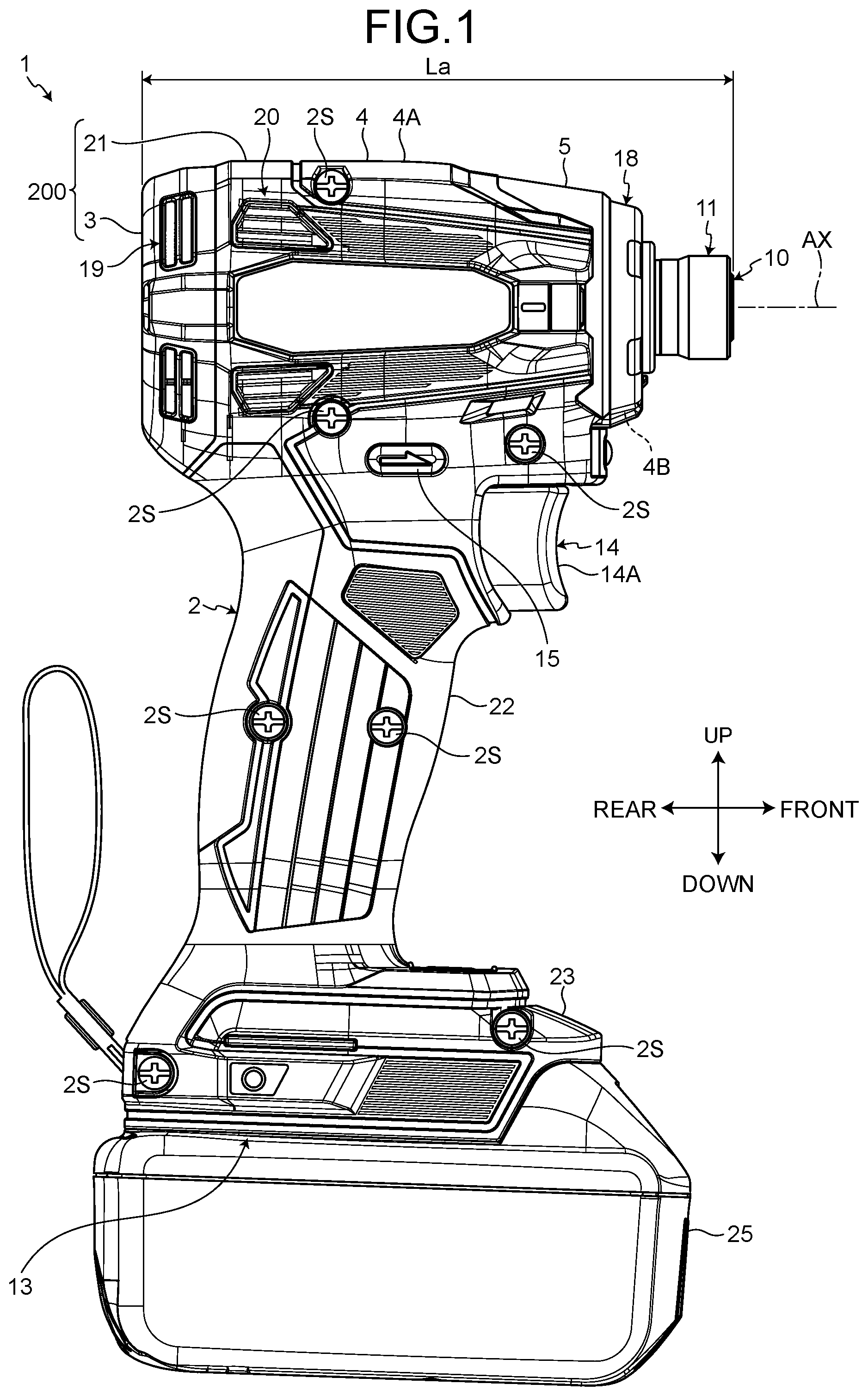
is a side view that shows an impact tool according to one representative, non-limiting embodiment of the present teachings.
is a front view that shows the impact tool according to the embodiment.
is a cross-sectional view that shows the impact tool according to the embodiment.
is an exploded, oblique view, viewed from the front, that shows a light unit according to the embodiment.
is a table that shows the specifications of a variety of known impact tools impact tools.
is a graph that shows the relationship between maximum tightening torque of an anvil and number of light-emitting devices according to the above-described known impact tools and the embodiment.
is a graph that shows the relationship between overall length of the impact tool and number of light-emitting devices according to the above-described known impact tools and the embodiment.
is a drawing that schematically shows a modified example of a light circuit board according to the embodiment.
is a drawing that schematically shows a modified example of the light circuit board according to the embodiment.
is a drawing that schematically shows a modified example of the light circuit board according to the embodiment.
DETAILED DESCRIPTION
As was mentioned above, in one or more embodiments, an impact tool may comprise: a brushless motor; a spindle, which is rotated by the brushless motor; a hammer, which is held on the spindle; an anvil, which is impacted in a rotational direction by the hammer; a motor housing, which is made of a resin (polymer) and houses the brushless motor; a hammer case, which is connected to the motor housing and houses the hammer and the spindle; and a battery-holding part, which is connected to the motor housing and on which a battery pack having a rated voltage of 18 V is mounted. The impact tool may comprise a light unit, which is held on the hammer case and comprises a plurality of light-emitting devices. The distance from a front-end portion of the anvil to a rear-end portion of the motor housing may be 100 mm or less. The maximum tightening torque of the anvil may be 210 N·m or more.
According to the above-mentioned configuration, because the light unit comprises the plurality of light-emitting devices, the work environment is brightly illuminated with illumination light. In addition, the distance from a front-end portion of the anvil to a rear-end portion of the motor housing is 100 mm or less, and the maximum tightening torque of the anvil is 210 N·m or more. Consequently, an impact tool having improved ergonomics and/or work efficiency is provided.
In one or more embodiments, at least three of the light-emitting devices may be provided. Thus, in an embodiment in which the maximum tightening torque of the anvil is 210 N·m or more and three light-emitting devices are provided, the maximum tightening torque divided by the total number of the light-emitting devices is 70 Nm or more.
According to the above-mentioned configuration, because the light unit comprises at least three of the light-emitting devices, the work environment is brightly illuminated with illumination light. Consequently, an impact tool having improved ergonomics and/or work efficiency is provided.
In one or more embodiments, the weight of the impact tool may be 1.5 kg or less.
According to the above-mentioned configuration, because the weight of the impact tool in the state in which the battery pack is mounted is 1.5 kg or less, an impact tool having improved ergonomics and/or work efficiency is provided.
In one or more embodiments, the maximum rotational speed of the anvil may be 3,000 rpm or less.
According to the above-mentioned configuration, because the maximum rotational speed of the anvil is 3,000 rpm or less, an impact tool having improved ergonomics and/or work efficiency is provided.
In one or more embodiments, an impact tool may comprise: a brushless motor; a spindle, which is rotated by the brushless motor; a hammer, which is held on the spindle; an anvil, which is impacted in a rotational direction by the hammer; a motor housing, which is made of a resin (polymer) and houses the brushless motor; a hammer case, which is connected to the motor housing and houses the hammer and the spindle; and a battery-holding part, which is connected to the motor housing and on which a battery pack having a rated voltage of 36 V is mounted. The impact tool may comprise a light unit, which is held on the hammer case and comprises a plurality of light-emitting devices. The distance from a front-end portion of the anvil to a rear-end portion of the motor housing may be 110 mm or less. The maximum tightening torque of the anvil may be 200 N·m or more.
According to the above-mentioned configuration, because the light unit comprises the plurality of light-emitting devices, the work environment is brightly illuminated with illumination light. In addition, the overall length, which is defined as the distance from the front-end portion of the anvil to the rear-end portion of the motor housing, is 110 mm or less, and the maximum tightening torque of the anvil is 200 N·m or more. Consequently, an impact tool having improved ergonomics and/or work efficiency is provided.
In one or more embodiments, the light unit may comprise: a light circuit board, which is disposed at least partially around the hammer case and holds the plurality of light-emitting devices; and optical members, which are disposed forward of the light-emitting devices and the light circuit board.
According to the above-mentioned configuration, the light-emitting devices and the light circuit board are protected by the optical members.
In one or more embodiments, an impact tool may comprise: a brushless motor; a spindle, which is rotated by the brushless motor; a hammer, which is held on the spindle; an anvil, which is impacted in a rotational direction by the hammer; a motor housing, which is made of a resin (polymer) and houses the brushless motor; a hammer case, which is connected to the motor housing and houses the hammer and the spindle; a battery-holding part, which is connected to the motor housing and on which a battery pack having a rated voltage of 18 V is mounted. The impact tool may comprise a light unit, which is held on the hammer case and comprises four light-emitting devices. The maximum tightening torque of the anvil may be 180 N·m or more.
According to the above-mentioned configuration, because the light unit comprises four of the light-emitting devices, the work environment is brightly illuminated with illumination light. In addition, the maximum tightening torque of the anvil is 180 N·m or more. Consequently, an impact tool having improved ergonomics and/or work efficiency is provided.
An embodiment is explained below, with reference to the drawings. In the embodiment, positional relationships among the parts are explained using the terms left, right, front, rear, up, and down. These terms indicate relative position or direction, wherein the center of an impact tool 1 is the reference. The impact tool 1 comprises a motor 6 , which serves as a motive power supply.
In the embodiment, the direction parallel to rotational axis AX of the motor 6 is called the axial direction where appropriate, the direction that goes around rotational axis AX is called the circumferential direction or the rotational direction where appropriate, and the radial direction of rotational axis AX is called the radial direction where appropriate.
Rotational axis AX extends in a front-rear direction. One side in the axial direction is forward, and the other side in the axial direction is rearward. In addition, in the radial direction, a location that is proximate to or a direction that approaches rotational axis AX is called radially inward where appropriate, and a location that is distant from or a direction that leads away from rotational axis AX is called radially outward where appropriate.
Impact Tool
is a side view that shows the impact tool 1 according to one representative, non-limiting embodiment of the present teachings. is a front view that shows the impact tool 1 according to the embodiment. is a cross-sectional view that shows the impact tool 1 according to the embodiment. In the embodiment, the impact tool 1 is an impact driver.
The impact tool 1 comprises a housing 2 , a rear cover 3 , a hammer case 4 , a hammer-case cover 5 , the motor 6 , a speed-reducing mechanism 7 , a spindle 8 , an impact mechanism 9 , an anvil 10 , a chuck mechanism 11 , a fan 12 , a battery-mounting part 13 , a trigger switch 14 , a forward/reverse-change lever 15 , an action-mode-change switch 16 , a controller 17 , and a light unit 18 .
The housing 2 houses at least the motor 6 . The housing 2 is made of a synthetic resin (polymer), such as nylon. The housing 2 is a resin (polymer) housing. The housing 2 comprises a pair of half housings. The housing 2 comprises a left housing 2 L and a right housing 2 R, which is disposed rightward of the left housing 2 L. The left housing 2 L and the right housing 2 R are fixed to each other by a plurality of screws 2 S.
The housing 2 comprises a motor-housing part 21 , a grip part 22 , and a battery-holding part 23 .
The motor-housing part 21 houses the motor 6 . The motor-housing part 21 is disposed around the motor 6 . The motor-housing part 21 has a tubular shape.
The grip part 22 is gripped by a user. The grip part 22 protrudes downward from the motor-housing part 21 . The trigger switch 14 is provided at an upper portion of the grip part 22 .
The battery-holding part 23 holds a battery pack 25 via the battery-mounting part 13 . The battery-holding part 23 houses the controller 17 . The battery-holding part 23 is connected to a lower-end portion of the grip part 22 . In both the front-rear direction and the left-right direction, the dimension of the outer shape of the battery-holding part 23 is larger than the dimension of the outer shape of the grip part 22 .
The rear cover 3 is fixed to a rear-end portion of the motor-housing part 21 . The rear cover 3 is made of a synthetic resin (polymer), such as nylon. The rear cover 3 is disposed such that it covers an opening in the rear-end portion of the motor-housing part 21 .
In the embodiment, a motor housing 200 , which is made of a resin (polymer), such as nylon, and houses the motor 6 , comprises the motor-housing part 21 and the rear cover 3 .
The hammer case 4 houses the speed-reducing mechanism 7 , the spindle 8 , the impact mechanism 9 , and at least a portion of the anvil 10 . The hammer case 4 is made of metal. The hammer case 4 has a tube shape. The hammer case 4 is connected to a front portion of the motor-housing part 21 . The hammer case 4 is sandwiched between the left housing 2 L and the right housing 2 R. A bearing box 24 is fixed to a rear portion of the hammer case 4 . The bearing box 24 is fixed to both the motor-housing part 21 and the hammer case 4 .
The hammer-case cover 5 covers at least a portion of the surface of the hammer case 4 . The hammer-case cover 5 is made of a synthetic resin (polymer), such as nylon. The hammer-case cover 5 protects the hammer case 4 . The hammer-case cover 5 blocks contact between the hammer case 4 and objects around the impact tool 1 . The hammer-case cover 5 blocks contact between the hammer case 4 and the user.
The motor 6 is the motive power supply of the impact tool 1 . The motor 6 is an inner-rotor-type brushless motor. The motor 6 is housed in the motor-housing part 21 , which is a portion of the housing 2 .
The motor 6 comprises a stator 26 and a rotor 27 . The stator 26 is supported by the motor-housing part 21 . At least a portion of the rotor 27 is disposed in the interior of the stator 26 . The rotor 27 rotates relative to the stator 26 . The rotor 27 rotates about rotational axis AX, which extends in the front-rear direction.
The stator 26 comprises a stator core 28 , a front insulator 29 , a rear insulator 30 , and coils 31 .
The stator core 28 is disposed more radially outward than the rotor 27 ; i.e. the stator core 28 radially surrounds the rotor 27 . The stator core 28 comprises a plurality of laminated steel sheets. Each of the steel sheets is a sheet made of a metal in which iron is the main component. The stator core 28 has a tube shape. The stator core 28 comprises teeth that respectively support the coils 31 .
The front insulator 29 is provided at a front portion of the stator core 28 . The rear insulator 30 is provided at a rear portion of the stator core 28 . The front insulator 29 and the rear insulator 30 are each an electrically insulating member that is made of a synthetic resin (polymer). The front insulator 29 is disposed such that it covers a portion of the surface of each of the teeth. The rear insulator 30 is disposed such that it covers a portion of the surface of each of the teeth.
The coils 31 are mounted on the stator core 28 via (over) the front insulator 29 and the rear insulator 30 . A plurality of the coils 31 is disposed. The coils 31 are respectively disposed around the teeth of the stator core 28 via (over) the front insulator 29 and the rear insulator 30 . The coils 31 and the stator core 28 are electrically insulated from each other by the front insulator 29 and the rear insulator 30 . Pairs of the coils 31 are respectively electrically connected via bus bars (short-circuiting members).
The rotor 27 rotates about rotational axis AX. The rotor 27 comprises a rotor core 32 , a rotor shaft 33 , rotor magnets 34 , and a sensor magnet 35 .
The rotor core 32 and the rotor shaft 33 are each made of steel. A front portion of the rotor shaft 33 protrudes forward from a front-end surface of the rotor core 32 . A rear portion of the rotor shaft 33 protrudes rearward from a rear-end surface of the rotor core 32 . The front portion and the rear portion of the rotor shaft 33 are each supported in a rotatable manner by rotor bearings 39 . The rotor bearing 39 on the front side is held by the bearing box 24 . The rotor bearing 39 on the rear side is held by the rear cover 3 . A front-end portion of the rotor shaft 33 is disposed in the internal space of the hammer case 4 through an opening in the bearing box 24 .
The rotor magnets 34 are fixed to the rotor core 32 . Each of the rotor magnets 34 has a circular-tube shape. The rotor magnets 34 are disposed around the rotor core 32 .
The sensor magnet 35 is fixed to the rotor core 32 . The sensor magnet 35 has a circular-ring shape. The sensor magnet 35 is disposed at a front-end surface of the rotor core 32 and front-end surfaces of the rotor magnets 34 .
A sensor board 37 is mounted on the front insulator 29 . The sensor board 37 comprises: a circuit board, which has a disk shape wherein a hole is provided at the center; and a rotation-detection device, which is supported by the circuit board. The rotation-detection device detects the position of the rotor 27 in the rotational direction by detecting the position of the sensor magnet 35 .
A pinion gear 41 is formed at a front-end portion of the rotor shaft 33 . The pinion gear 41 is coupled to at least a portion of the speed-reducing mechanism 7 . The rotor shaft 33 is coupled to the speed-reducing mechanism 7 via the pinion gear 41 .
The speed-reducing mechanism 7 couples the rotor shaft 33 and the spindle 8 to each other. The speed-reducing mechanism 7 transmits the rotation of the rotor 27 to the spindle 8 . The speed-reducing mechanism 7 causes the spindle 8 to rotate at a rotational speed that is lower than the rotational speed of the rotor 27 , but at a higher torque. The speed-reducing mechanism 7 comprises a planetary-gear mechanism. The speed-reducing mechanism 7 is disposed forward of the motor 6 .
The speed-reducing mechanism 7 comprises a plurality of planet gears 42 disposed around the pinion gear 41 and an internal gear 43 disposed around the plurality of planet gears 42 . The pinion gear 41 , the planet gears 42 , and the internal gear 43 are each housed in the hammer case 4 and the bearing box 24 . Each of the planet gears 42 meshes with the pinion gear 41 . The planet gears 42 are supported in a rotatable manner by the spindle 8 via pins 42 P. The spindle 8 is rotated by the planet gears 42 . The internal gear 43 has inner teeth, which mesh with the planet gears 42 . The internal gear 43 is fixed to the bearing box 24 . The internal gear 43 is always non-rotatable relative to the bearing box 24 .
When the rotor shaft 33 rotates in response to the operation (energization) of the motor 6 , the pinion gear 41 rotates, and the planet gears 42 revolve around the pinion gear 41 . The planet gears 42 revolve while meshing with the inner teeth of the internal gear 43 . In response to the revolving of the planet gears 42 , the spindle 8 , which is connected to the planet gears 42 via the respective pins 42 P, rotates at a rotational speed that is lower than the rotational speed of the rotor shaft 33 .
The spindle 8 is rotated by the motor 6 . The spindle 8 rotates in response to the rotational force of the rotor 27 transmitted by the speed-reducing mechanism 7 . The spindle 8 is housed in the hammer case 4 . The spindle 8 is disposed forward of the motor 6 . At least a portion of the spindle 8 is disposed forward of the speed-reducing mechanism 7 .
The spindle 8 comprises a spindle-shaft part 8 A and a flange part 8 B, which is disposed at a rear portion of the spindle-shaft part 8 A. The spindle-shaft part 8 A protrudes forward from the flange part 8 B. The planet gears 42 are supported in a rotatable manner by the flange part 8 B via the respective pins 42 P. The rotational axis of the spindle 8 and rotational axis AX of the motor 6 coincide with each other. The spindle 8 rotates about rotational axis AX.
The spindle 8 is supported in a rotatable manner by a spindle bearing 44 . The spindle bearing 44 is held by the bearing box 24 .
The impact mechanism 9 impacts the anvil 10 in the rotational direction in response to transmission of the rotational force of the spindle 8 . The rotational force of the motor 6 is transmitted to the impact mechanism 9 via the speed-reducing mechanism 7 and the spindle 8 . The impact mechanism 9 comprises a hammer 47 , balls 48 , and a coil spring 49 . The impact mechanism 9 , which comprises the hammer 47 , is housed in the hammer case 4 .
The hammer 47 is configured to impact (strike) the anvil 10 in the rotational direction, as will be further described below. The hammer 47 is held on the spindle 8 . The hammer 47 is disposed around the spindle-shaft part 8 A. The balls 48 are disposed between the spindle 8 and the hammer 47 . The coil spring 49 is supported by both the spindle 8 and the hammer 47 .
The hammer 47 is rotatable, together with the spindle 8 , in response to transmission of the rotational force of the spindle 8 . The rotational axis of the hammer 47 , the rotational axis of the spindle 8 , and rotational axis AX of the motor 6 coincide with each other. The hammer 47 rotates about rotational axis AX.
Each of the balls 48 is made of a metal such as steel. The balls 48 are disposed between the spindle-shaft part 8 A and the hammer 47 . The spindle 8 has spindle grooves, in which at least portions of the balls 48 are respectively disposed. The spindle grooves are provided in portions of an outer surface of the spindle-shaft part 8 A. The hammer 47 has hammer grooves, in which at least portions of the balls 48 are respectively disposed. The hammer grooves are provided in portions of an inner surface of the hammer 47 . The balls 48 are respectively disposed between the spindle grooves and the hammer grooves. The balls 48 can respectively roll in each of the interiors of the spindle grooves and the interiors of the hammer grooves. The hammer 47 is capable of moving along with the balls 48 . The spindle 8 and the hammer 47 are capable of relative movement in both the axial direction and the rotational direction within a movable range that is defined by the spindle grooves and the hammer grooves.
The coil spring 49 generates an elastic restoring force, which causes (biases) the hammer 47 to move forward. The coil spring 49 is disposed between the flange part 8 B and the hammer 47 . A recessed portion is provided on a rear surface of the hammer 47 . The recessed portion recesses forward from a rear surface of the hammer 47 . A washer 45 is provided in the interior of the recessed portion. A rear-end portion of the coil spring 49 is supported by the flange part 8 B. A front-end portion of the coil spring 49 is supported by the washer 45 .
The anvil 10 is the output part of the impact tool 1 , on which a tool accessory is mounted. The anvil 10 is disposed forward of the spindle 8 . The anvil 10 is connected to a front-end portion of the spindle-shaft part 8 A. At least a portion of the anvil 10 is disposed forward of the hammer 47 . The anvil 10 has an insertion hole 10 C, into which a tool accessory is inserted.
The anvil 10 comprises an anvil-shaft part 10 A and anvil-projection parts 10 B. The insertion hole 10 C is provided such that it extends rearward from a front-end portion of the anvil-shaft part 10 A. The anvil-projection parts 10 B protrude radially outward from a rear-end portion of the anvil-shaft part 10 A.
The anvil 10 is supported in a rotatable manner by an anvil bearing. The rotational axis of the anvil 10 , the rotational axis of the hammer 47 , the rotational axis of the spindle 8 , and rotational axis AX of the motor 6 coincide with each other. The anvil 10 rotates about rotational axis AX. The anvil bearing is held by the hammer case 4 . A ball bearing is an illustrative example of the anvil bearing.
At least portions of the hammer 47 are capable of making contact with the anvil-projection parts 10 B. Hammer-projection parts, which protrude forward, are provided at a front portion of the hammer 47 . The hammer-projection parts of the hammer 47 and the anvil-projection parts 10 B are capable of making contact with each another. In the state in which the hammer 47 and the anvil-projection parts 10 B are in contact with each another, the anvil 10 rotates together with the hammer 47 and the spindle 8 in response to the (energization) operation of the motor 6 .
However, the anvil 10 is always configured to be impacted (struck) in the rotational direction by the hammer 47 . For example, during screw-tightening work, there are situations in which, when the load that acts on the anvil 10 becomes high (exceeds a predetermined threshold), the anvil 10 can no longer be caused to rotate merely by the power generated by the motor 6 . Instead, when the anvil 10 can no longer be caused to rotate merely by the power generated by the motor 6 , the rotation of the anvil 10 and the hammer 47 will temporarily stop. The spindle 8 and the hammer 47 can move relative to each another in the axial direction and the circumferential direction via the balls 48 . Even though the rotation of the hammer 47 temporarily stops, the rotation of the spindle 8 continues owing to the power generated by the motor 6 . In the state in which the rotation of the hammer 47 has temporarily stopped but the spindle 8 continues to rotate, the balls 48 move rearward while being guided by the respective spindle grooves and hammer grooves. The hammer 47 receives a force from the balls 48 and moves rearward along with the balls 48 . That is, in the state in which the rotation of the anvil 10 is temporarily stopped, the hammer 47 moves rearward in response to the rotation of the spindle 8 . The contact between the hammer 47 and the anvil-projection parts 10 B is released by the movement of the hammer 47 rearward.
As was noted above, because the coil spring 49 generates an elastic restoring force, it causes (urges) the hammer 47 to move forward. Therefore, after the hammer 47 has been caused to move rearward, it will subsequently move forward owing to the elastic force of the coil spring 49 . When the hammer 47 moves forward, it receives a force in the rotational direction from the balls 48 . That is, the hammer 47 moves forward while rotating. When the hammer 47 moves forward while rotating, the hammer 47 makes contact with (impacts, strikes) the anvil-projection parts 10 B while rotating. Thereby, the anvil-projection parts 10 B are impacted in the rotational direction by the hammer 47 . At this time, both the power of the motor 6 and the inertial force of the hammer 47 act on the anvil 10 . As a result, the anvil 10 can be caused to rotate about rotational axis AX with a higher torque.
The chuck mechanism 11 is disposed around a front portion of the anvil 10 . The chuck mechanism 11 holds the tool accessory that has been inserted into the insertion hole.
The fan 12 generates an airflow for cooling the motor 6 . The fan 12 is fixed to a rear portion of the rotor shaft 33 . The fan 12 rotates in response to the rotation of the rotor 27 . In other words, in response to the rotor shaft 33 rotating, the fan 12 rotates together with the rotor shaft 33 . The motor-housing part 21 is provided with air-intake openings 20 , and the rear cover 3 is provided with air-exhaust openings 19 . In response to the rotation of the fan 12 , air in the external space of the housing 2 flows into the internal space of the housing 2 via the air-intake openings 20 . The air that has flowed into the internal space of the housing 2 flows through the internal space of the housing 2 , and thereby cools the motor 6 . In response to the rotation of the fan 12 , the air that has flowed through the internal space of the housing 2 flows out to the external space of the housing 2 via the air-exhaust openings 19 .
The battery-mounting part 13 is connected to the battery pack 25 . The battery pack 25 is mounted on the battery-mounting part 13 . The battery pack 25 is detachable from the battery-mounting part 13 . The battery-mounting part 13 is disposed at a lower portion of the battery-holding part 23 . The battery pack 25 is mounted on the battery-holding part 23 , which is a portion of the housing 2 , via the battery-mounting part 13 .
The battery pack 25 comprises secondary batteries. In the embodiment, the battery pack 25 comprises rechargeable lithium-ion batteries. By being mounted on the battery-mounting part 13 , the battery pack 25 can supply electric power (current) to the impact tool 1 . The motor 6 operates (is energized) using electric power supplied from the battery pack 25 . The controller 17 operates (is powered) using electric power supplied from the battery pack 25 .
In the embodiment, the rated voltage of the battery pack 25 is 18 V.
The trigger switch 14 is manipulated (e.g., pressed) by the user in order to start (the energization of) the motor 6 . The trigger switch 14 is provided on the grip part 22 . The trigger switch 14 comprises a trigger lever 14 A and a switch main body 14 B. The switch main body 14 B is housed in the grip part 22 . The trigger lever 14 A protrudes forward from an upper portion of a front portion of the grip part 22 . In response to the trigger lever 14 A being manipulated by the user, the motor 6 is switched between operation (energization) and stoppage.
The forward/reverse-change lever 15 is manipulated (pressed, slid) by the user in order to change the rotational direction of the motor 6 from one of the forward-rotational direction and the reverse-rotational direction to the other. The forward/reverse-change lever 15 is provided at an upper portion of the grip part 22 . In response to the forward/reverse-change lever 15 being manipulated, the rotational direction of the motor 6 is changed from one of the forward-rotational direction and the reverse-rotational direction to the other. In response to the rotational direction of the motor 6 being changed, the rotational direction of the spindle 8 is changed.
The action-mode-change switch 16 is manipulated by the user in order to change the control mode of the motor 6 , e.g., a sequence of motor rotational speeds. The action-mode-change switch 16 is provided on the battery-holding part 23 .
The controller 17 outputs control signals that control at least (the energization of) the motor 6 . The controller 17 is housed in the battery-holding part 23 . The controller 17 comprises a circuit board on which a plurality of electronic components is mounted. A processor, such as a CPU (central processing unit); nonvolatile memory, such as ROM (read-only memory) and storage; volatile memory, such as RAM (random-access memory); transistors; and resistors are illustrative examples of the electronic components mounted on the circuit board.
Light Unit
is an exploded, oblique view, viewed from the front, that shows the light unit 18 according to the embodiment. The light unit 18 emits illumination light. The light unit 18 illuminates the anvil 10 and the periphery of the anvil 10 with illumination light. The light unit 18 illuminates forward of the anvil 10 with illumination light. In addition, the light unit 18 illuminates the tool accessory mounted on the anvil 10 and the periphery of the tool accessory with illumination light.
The light unit 18 is held on the hammer case 4 . The light unit 18 is disposed at (on) a front portion of the hammer case 4 . The light unit 18 is disposed at least partially around the hammer case 4 .
The hammer case 4 comprises a hammer-housing part 4 A and a bearing-retaining part 4 B. The hammer-housing part 4 A has a tube shape. The hammer-housing part 4 A is disposed around the impact mechanism 9 . The hammer-housing part 4 A houses at least the hammer 47 . The bearing-retaining part 4 B has a tube shape. The bearing-retaining part 4 B is disposed more forward than the hammer-housing part 4 A. The outer diameter of the bearing-retaining part 4 B is smaller than the outer diameter of the hammer-housing part 4 A. The bearing-retaining part 4 B is disposed around the anvil bearing. The bearing-retaining part 4 B holds the anvil bearing.
The light unit 18 is disposed around the bearing-retaining part 4 B. A rear portion of the hammer-housing part 4 A is housed in the motor-housing part 21 .
The light unit 18 comprises light-emitting devices 60 , a light circuit board 61 , optical members 62 , and a light cover 63 .
Each of the light-emitting devices 60 is a light source that emits illumination light. Light-emitting diodes (LEDs) are illustrative examples of the light-emitting devices 60 .
The plurality of the light-emitting devices 60 is provided such that the light-emitting devices 60 are spaced apart around the anvil 10 . The number of light-emitting devices 60 is, for example, two or more and eight or less. At least three of the light-emitting devices 60 may be provided. The number of light-emitting devices 60 may be, for example, three or more and six or less. In the embodiment, four of the light-emitting devices 60 are provided around the anvil 10 .
The light circuit board 61 supports the plurality of light-emitting devices 60 . The light circuit board 61 is disposed at least partially around the hammer case 4 . In the embodiment, the light circuit board 61 is disposed partially around the hammer case 4 . The light circuit board 61 is disposed partially around the bearing-retaining part 4 B.
The light circuit board 61 comprises a printed wiring board (PWB) or printed circuit board (PCB). The light circuit board 61 has wiring (traces, conductive paths) that is (are) connected to the light-emitting devices 60 . Electric power (current) is supplied to the light-emitting devices 60 via the wiring of the light circuit board 61 . The light-emitting devices 60 are mounted on a front surface of the light circuit board 61 . In the embodiment, the light unit 18 comprises surface-mount-type (SMD: surface-mount device) light-emitting diodes. Each of the light-emitting devices 60 comprises a so-called chip LED.
The voltage input to each one of the light-emitting devices 60 is 1.0 volt (V) or more and 10.0 V or less. The voltage applied to each one of the light-emitting devices 60 may be, for example, 2.0 V or more and 8.0 V or less or may be 2.5 V or more and 5.0 V or less.
Electric current supplied to each one of the light-emitting devices 60 is 5 milliamps (mA) or more and 100 mA or less. Electric current supplied to each one of the light-emitting devices 60 may be 10 mA or more and 50 mA or less or may be 15 mA or more and 30 mA or less.
The light beam of the illumination light emitted from each one of the light-emitting devices 60 is 1 lumen (lm) or more and 20 lm or less. The light beam of the illumination light emitted from each one of the light-emitting devices 60 may be 3 lm or more and 15 lm or less or may be 5 lm or more and 10 lm or less.
The luminous intensity of the illumination light emitted from each one of the light-emitting devices 60 is 0.5 candela (cd) or more and 10 cd or less. The luminous intensity of the illumination light emitted from each one of the light-emitting devices 60 may be 1 cd or more and 7 cd or less or may be 2 cd or more and 5 cd or less.
As shown in , the outer shape of each one of the light-emitting devices 60 is substantially rectangular-parallelepiped-shaped.
Width W of each one of the light-emitting devices 60 is 0.5 millimeters (mm) or more and 3 mm or less. Width W of each one of the light-emitting devices 60 may be 1 mm or more and 2 mm or less or may be 1.2 mm or more and 1.8 mm or less.
Length L of each one of the light-emitting devices 60 is 1.5 mm or more and 6 mm or less. Length L of each one of the light-emitting devices 60 may be 2.5 mm or more and 3.5 mm or less.
Thickness H of each one of the light-emitting devices 60 is 0.2 mm or more and 2 mm or less. Thickness H of each one of the light-emitting devices 60 may be 0.3 mm or more and 1 mm or less or may be 0.4 mm or more and 0.8 mm or less.
The optical members 62 are disposed forward of the light-emitting devices 60 and the light circuit board 61 . Each of the optical members 62 comprises: light-transmitting parts 62 A, which transmits the illumination light emitted from the corresponding light-emitting devices 60 ; and a coupling part 62 B, which is connected to the light-transmitting parts 62 A.
In the embodiment, the optical members 62 comprise an optical member 62 L, which is disposed more leftward than rotational axis AX, and an optical member 62 R, which is disposed more rightward than rotational axis AX. As can be seen, e.g., in , the optical members 62 L, 62 R do not directly contact each other when integrated into the light cover 63 , but are indirectly connected (linked) to each other via the material of the light cover 63 in the integrated state. The optical member 62 L comprises two of the light-transmitting parts 62 A. The optical member 62 R comprises two of the light-transmitting parts 62 A. Of the four light-emitting devices 60 , the two light-emitting devices 60 disposed more leftward than rotational axis AX respectively oppose the two light-transmitting parts 62 A of the optical member 62 L. Of the four light-emitting devices 60 , the two light-emitting devices 60 disposed more rightward than rotational axis AX respectively oppose the two light-transmitting parts 62 A of the optical member 62 R.
Each of the optical members 62 , in particular light-transmitting parts 62 A thereof (see below), is formed of an optically transmissive synthetic resin (polymer). In the embodiment, each of the optical members 62 is formed of a polycarbonate resin (polymer). It is noted that each of the optical members 62 may be formed of an acrylic resin (polymer).
Each of the light-transmitting parts 62 A has a lens function. Each of the light-transmitting parts 62 A refracts illumination light emitted from the corresponding light-emitting device 60 . It is noted that each of the light-transmitting parts 62 A does not have to have a lens function.
The light cover 63 is disposed forward of the light-emitting devices 60 and the light circuit board 61 . In the embodiment, the light cover 63 is substantially ring-shaped.
The light cover 63 is formed of a synthetic resin (polymer). The light cover 63 may be formed of a material the same as that of the optical members 62 . The light cover 63 may be formed of a material that differs from that of the optical members 62 . In the embodiment, the light cover 63 is formed of a polycarbonate resin (polymer). It is noted that the light cover 63 may be formed of an acrylic resin (polymer). The optical members 62 and the light cover 63 are integrally molded. The optical members 62 and the light cover 63 are integrated by, for example, insert molding.
As can be seen in , openings 63 A are provided spaced part in different portions of the light cover 63 . The light-transmitting parts 62 A of the optical members 62 are respectively disposed in the openings 63 A of the light cover 63 such that the light-transmitting parts 62 A are separated from each other on the outer surface of the light cover 63 and such that the light-transmitting parts 62 A respectively face the light-emitting devices 60 in a fixed relationship with the corresponding light-emitting devices 60 ; i.e. the light-transmitting parts 62 A are immovable relative to the light-emitting devices 60 . The light-transmitting parts 62 A are not covered by the light cover 63 . That is, the light cover 63 is not disposed forward or rearward of the light-transmitting parts 62 A. The coupling parts 62 B of the optical members 62 are fixed to the light cover 63 . The light cover 63 is connected to the ring-shaped circuit board 61 such that the light cover 63 is immovable relative to the ring-shaped circuit board 61 .
The optical members 62 and the light cover 63 are disposed around the bearing-retaining part 4 B. The optical members 62 and the light cover 63 are supported on the hammer case 4 via the hammer-case cover 5 .
The optical members 62 and the light cover 63 protect the light-emitting devices 60 and the light circuit board 61 . The optical members 62 and the light cover 63 block contact between objects around the impact tool 1 on one side and the light-emitting devices 60 and the light circuit board 61 on the other side. The optical members 62 and the light cover 63 are integrally molded such that a gap is not formed between the optical members 62 and the light cover 63 . The optical members 62 and the light cover 63 have a dustproofing function that inhibits the ingress of moisture to the light-emitting devices 60 and the light circuit board 61 . The optical members 62 and the light cover 63 have a dustproofing function that inhibits the ingress of dust to the light-emitting devices 60 and the light circuit board 61 .
Relationship Between Maximum Tightening Torque and Number of Light-Emitting Devices
is a table that shows the specifications of a variety of known impact drivers. shows the specifications for: Product A, Product B, and Product C, which are impact drivers manufactured and sold by Company a; Product D, Product E, and Product F, which are impact drivers manufactured and sold by Company B; Product G, Product H, and Product I, which are impact drivers manufactured and sold by Company y; and Product J, Product K, and Product L, which are impact drivers manufactured and sold by Company 8 . Each product from Product A to Product L has structural elements equivalent to the structural elements of the impact tool 1 , which was described above with reference to to . A battery pack is mounted on each product from Product A to Product L.
The number of light-emitting devices, the maximum tightening torque [N·m] of the anvil, the rated voltage [V] of the battery pack, the weight [kg] of the impact driver in the state in which the battery pack is mounted, the overall length [mm] indicating the distance from the front-end portion of the anvil to the rear-end portion of the motor-housing part, and the maximum rotational speed [rpm] of the anvil are illustrative examples of the specifications of the impact driver.
As shown in , the number of light-emitting devices is three for Product A, and similarly is three for Product B, three for Product C, one for Product D, one for Product E, one for Product F, one for Product G, one for Product H, one for Product I, one for Product J, one for Product K, and one for Product L.
As shown in , the maximum tightening torque is 206 N·m for Product A, and, expressed in a similar manner, is 159 N·m for Product B, 147 N·m for Product C, 203 N·m for Product D, 226 N·m for Product E, 181 N·m for Product F, 170 N·m for Product G, 158 N·m for Product H, 181 N·m for Product I, 240 N·m for Product J, 240 N·m for Product K, and 135 N·m for Product L.
As shown in , the overall length is 134.6 mm for Product A, and, in a similar manner, is 141 mm for Product B, 146.1 mm for Product C, 133.4 mm for Product D, 116.6 mm for Product E, 29.5 mm for Product F, 144.8 mm for Product G, 149.9 mm for Product H, 170.18 mm for Product I, 152 mm for Product J, 168 mm for Product K, and 150 mm for Product L.
The values of the rated voltage (V) of the battery pack, the weight (kg) of the impact driver in the state in which the battery pack is mounted, and the maximum rotational speed (rpm) of the anvil are as shown in .
In each product from Product A to Product L, the rated voltage of the battery pack is roughly 18 V.
is a graph that shows the relationship between maximum tightening torque of the anvil and number of light-emitting devices according to both the above-described known impact tools and the embodiment. In the graph shown in , the abscissa is the number of light-emitting devices, and the ordinate is the maximum tightening torque of the anvil. The points shown in plot the relationship between maximum tightening torque of the anvil and number of the light-emitting devices for each product from Product A to Product L shown in .
To provide an impact tool 1 having improved ergonomics and/or work efficiency, it is effective to brightly illuminate the work environment with illumination light using the light unit 18 . In addition, for the same purpose, it is effective to shorten the overall length. On the other hand, if the maximum tightening torque becomes large, there is a tendency for the overall length of the impact tool 1 to become large. It is important to decide on a suitable tradeoff between overall length and maximum tightening torque of the impact tool 1 .
As described above, the impact tool 1 comprises a plurality of structural elements, such as the motor 6 , the spindle 8 , the impact mechanism 9 , the anvil 10 , and the light unit 18 . By optimizing these structural elements, an improved impact tool 1 can be provided. In the present specification, the structural elements of the impact tool 1 are optimized, and thereby the impact tool 1 , in which ergonomics and/or work efficiency is (are) better than in the above-described known impact drivers, is provided.
With regard to the impact tool 1 according to the embodiment, the battery pack 25 having a rated voltage of 18 V is mounted. As shown by the hatched area in , the impact tool 1 according to the embodiment comprises the plurality of light-emitting devices 60 , and the maximum tightening torque of the anvil 10 is 210 N·m or more. An impact driver wherein the battery pack 25 having a rated voltage of 18 V is mounted, the plurality of light-emitting devices is provided, and the maximum tightening torque of the anvil 10 is 210 N·m or more does not exist in the above-described known impact tools. It is noted that the maximum tightening torque of the anvil 10 may be 210 N·m or more and 300 N·m or less.
In addition, the impact tool 1 according to the embodiment comprises four of the light-emitting devices 60 , and the maximum tightening torque of the anvil 10 is 180 N·m or more. An impact driver wherein the battery pack 25 having a rated voltage of 18 Vis mounted, four of the light-emitting devices are provided, and the maximum tightening torque of the anvil 10 is 180 N·m or more does not exist in the above-described known impact tools. It is noted that the maximum tightening torque of the anvil 10 may be 180 N·m or more and 300 N·m or less.
Relationship Between Overall Length and Number of Light-Emitting Devices In addition, to provide an impact tool 1 having improved ergonomics and/or work efficiency, it is effective to optimize the overall length of the impact tool 1 . As shown in , overall length La of the impact tool 1 is the distance from a front-end portion of the anvil 10 to a rear-end portion of the motor housing 200 (rear-end portion of the rear cover 3 ).
is a graph that shows the relationship between overall length of the impact tool and number of the light-emitting devices according to both the above-described known impact tools and the embodiment. In the graph shown in , the abscissa is the number of light-emitting devices, and the ordinate is the overall length of the impact tool. The points shown in plot the relationship between overall length of the impact tool and number of the light-emitting devices for each product from Product A to Product L shown in .
With regard to the impact tool 1 according to the present embodiment, the battery pack 25 having a rated voltage of 18 V is mounted. As shown by the hatched area in , the impact tool 1 according to the embodiment comprises a plurality of the light-emitting devices 60 and has overall length La of 100 mm or less. An impact driver wherein the battery pack 25 having a rated voltage of 18 V is mounted and that comprises the plurality of the light-emitting devices and having an overall length of 100 mm or less does not exist in the above-described known impact tools.
It is noted that, in the impact tool 1 comprising the plurality of light-emitting devices 60 and wherein the maximum tightening torque of the anvil 10 is 1,000 N·m or more and 2,500 N·m or less, overall length La of the impact tool 1 may be 155 mm or less.
Relationship Between Weight of Impact Tool and Maximum Rotational Speed of Anvil
In addition, to provide an impact tool 1 having improved ergonomics and/or work efficiency, it is effective to optimize the weight of the impact tool 1 . In the embodiment, the weight of the impact tool is the weight of the impact tool in the state in which the battery pack is mounted. In addition, to provide an impact tool 1 having improved ergonomics and/or work efficiency, it is effective to optimize the maximum rotational speed of the anvil 10 .
In the embodiment, the weight of the impact tool 1 is 1.5 kg or less. In addition, the maximum rotational speed of the anvil 10 is 3,000 rpm or less.
Effects
As explained above, an impact tool 1 comprises: a motor 6 ; a spindle 8 , which is rotated by the motor 6 ; a hammer 47 , which is held on the spindle 8 ; an anvil 10 , which is impacted in a rotational direction by the hammer 47 ; a motor housing 200 , which is made of a resin (polymer) and houses the motor 6 ; a hammer case 4 , which is connected to the motor housing 200 and houses the hammer 47 and the spindle 8 ; and a batter-holding part 23 , which is connected to the motor housing 200 and on which the battery pack 25 having a rated voltage of 18 V is mounted. The impact tool 1 comprises a light unit 18 , which is held on the hammer case 4 and comprises a plurality of light-emitting devices 60 . Overall length La indicating the distance from a front-end portion of the anvil 10 to a rear-end portion of the motor housing 200 is 100 mm or less. The maximum tightening torque of the anvil 10 is 210 N·m or more.
According to the above-mentioned configuration, because the light unit 18 comprises the plurality of light-emitting devices 60 , the work environment is brightly illuminated with illumination light. In addition, overall length La indicating the distance from a front-end portion of the anvil 10 to a rear-end portion of the motor housing 200 is 100 mm or less, and the maximum tightening torque of the anvil 10 is 210 N·m or more. Consequently, an impact tool 1 having improved ergonomics and/or work efficiency is provided.
In the embodiment, at least three of the light-emitting devices 60 are provided.
According to the above-mentioned configuration, because the light unit 18 comprises at least three of the light-emitting devices 60 , the work environment is brightly illuminated with illumination light. Consequently, an impact tool 1 having improved ergonomics and/or work efficiency is provided.
In the embodiment, the weight of the impact tool 1 is 1.5 kg or less.
According to the above-mentioned configuration, because the weight of the impact tool 1 in the state in which the battery pack 25 is mounted is 1.5 kg or less, an impact tool 1 having improved ergonomics and/or work efficiency is provided.
In the embodiment, the maximum rotational speed of the anvil 10 is 3,000 rpm or less.
According to the above-mentioned configuration, because the maximum rotational speed of the anvil 10 is 3,000 rpm or less, an impact tool 1 having improved ergonomics and/or work efficiency is provided.
In the embodiment, the light unit 18 comprises: a light circuit board 61 , which is disposed at least partially around the hammer case 4 and holds a plurality of the light-emitting devices 60 ; and optical members 62 , which are disposed forward of the light-emitting devices 60 and the light circuit board 61 .
According to the above-mentioned configuration, the light-emitting devices 60 and the light circuit board 61 are protected by the optical members 62 .
In one or more embodiments, the impact tool 1 comprises: the motor 6 ; the spindle 8 , which is rotated by the motor 6 ; the hammer 47 , which is held on the spindle 8 ; the anvil 10 , which is impacted in a rotational direction by the hammer 47 ; the motor housing 200 , which is made of a resin (polymer) and houses the motor 6 ; the hammer case 4 , which is connected to the motor housing 200 and houses the hammer 47 and the spindle 8 ; the battery-holding part 23 , which is connected to the motor housing 200 and on which the battery pack 25 having a rated voltage of 18 V is mounted. The impact tool 1 comprises the light unit 18 , which is held on the hammer case 4 and comprises four light-emitting devices 60 . The maximum tightening torque of the anvil 10 is 180 N·m or more.
According to the above-mentioned configuration, because the light unit 18 comprises four of the light-emitting devices 60 , the work environment is brightly illuminated with illumination light. In addition, the maximum tightening torque of the anvil 10 is 180 N·m or more. Consequently, an impact tool 1 having improved ergonomics and/or work efficiency is provided.
Modified Examples
schematically show modified examples of the light circuit board 61 according to the above-described embodiment. As shown in , a light circuit board 61 A may have a ring shape. As shown in , a light circuit board 61 B may have an arc shape. A gap 61 G is provided between one-end portion and the other-end portion of the light circuit board 61 B. As shown in , the gap 61 G between one-end portion and the other-end portion of a light circuit board 61 C may be large.
In the embodiment described above, the rated voltage of the battery pack 25 mounted on the battery-holding part 23 may be 36 V. In the impact tool 1 wherein the battery pack 25 having a rated voltage of 36 V is mounted, overall length La, which is defined as the distance from a front-end portion of the anvil 10 to a rear-end portion of the motor housing 200 , may be 110 mm or less, and the maximum tightening torque of the anvil 10 may be 200 N·m or more. In the above-mentioned configuration as well, because the light unit 18 comprises the plurality of light-emitting devices 60 , the work environment is brightly illuminated with illumination light. In addition, because overall length La, which is defined as the distance from the front-end portion of the anvil 10 to the rear-end portion of the motor housing 200 , is 110 mm or less and the maximum tightening torque of the anvil 10 is 200 N·m or more, an impact tool 1 having improved ergonomics and/or work efficiency is provided.
In the embodiments described above, it is assumed that the impact tool 1 is an impact driver. The impact tool 1 may be an impact wrench.
In the embodiments described above, the power supply of the impact tool 1 does not have to be the battery pack 25 and may be commercial power supply (AC power supply).
Representative, non-limiting examples of the present invention were described above in detail with reference to the attached drawings. This detailed description is merely intended to teach a person of skill in the art further details for practicing preferred aspects of the present teachings and is not intended to limit the scope of the invention. Furthermore, each of the additional features and teachings disclosed above may be utilized separately or in conjunction with other features and teachings to provide improved impact tools, such as impact wrenches and impact drivers.
Moreover, combinations of features and steps disclosed in the above detailed description may not be necessary to practice the invention in the broadest sense, and are instead taught merely to particularly describe representative examples of the invention. Furthermore, various features of the above-described representative examples, as well as the various independent and dependent claims below, may be combined in ways that are not specifically and explicitly enumerated in order to provide additional useful embodiments of the present teachings.
All features disclosed in the description and/or the claims are intended to be disclosed separately and independently from each other for the purpose of original written disclosure, as well as for the purpose of restricting the claimed subject matter, independent of the compositions of the features in the embodiments and/or the claims. In addition, all value ranges or indications of groups of entities are intended to disclose every possible intermediate value or intermediate entity for the purpose of original written disclosure, as well as for the purpose of restricting the claimed subject matter.
EXPLANATION OF THE REFERENCE NUMBERS
•
• 1 Impact tool • 2 Housing • 3 Rear cover • 2 L Left housing • 2 R Right housing • 2 S Screw • 4 Hammer case • 4 A Hammer-housing part • 4 B Bearing-retaining part • 5 Hammer-case cover • 6 Motor • 7 Speed-reducing mechanism • 8 Spindle • 8 A Spindle-shaft part • 8 B Flange part • 9 Impact mechanism • 10 Anvil • 10 A Anvil-shaft part • 10 B Anvil-projection part • 10 C Insertion hole • 11 Check mechanism • 12 Fan • 13 Battery-mounting part • 14 Trigger switch • 14 A Trigger lever • 14 B Switch main body • 15 Forward/reverse-change lever • 16 Mode-change switch • 17 Controller • 18 Light unit • 19 Air-exhaust opening • 20 Air-intake opening • 21 Motor-housing part • 22 Grip part • 23 Battery-holding part • 24 Bearing box • 25 Battery pack • 26 Stator • 27 Rotor • 28 Stator core • 29 Front insulator • 30 Rear insulator • 31 Coil • 32 Rotor core • 33 Rotor shaft • 34 Rotor magnet • 35 Sensor magnet • 37 Sensor board • 39 Rotor bearing • 41 Pinion gear • 42 Planet gear • 42 P Pin • 43 Internal gear • 44 Spindle bearing • 45 Washer • 47 Hammer • 48 Ball • 49 Coil spring • 60 Light-emitting device • 61 Light circuit board • 61 A Light circuit board • 61 B Light circuit board • 61 C Light circuit board • 61 G Gap • 62 Optical member • 62 A Light-transmitting part • 62 B Coupling part • 62 L Optical member • 62 R Optical member • 63 Light cover • 63 A Opening • 200 Motor housing • AX Rotational axis • H Thickness • L Length • La Overall length • W Width
Figures (8)
Citations
This patent cites (78)
- US4936171
- US5525842
- US5584565
- US7726863
- US8371848
- US8496366
- US8827483
- US9028088
- US9352458
- US9774273
- US10525582
- US10850383
- US11453106
- US11958170
- US12194602
- US2003/0002934
- US2003/0058638
- US2003/0095402
- US2004/0174699
- US2005/0157489
- US2006/0092674
- US2008/0266845
- US2009/0256319
- US2010/0149790
- US2010/0214768
- US2010/0224033
- US2011/0180286
- US2011/0187211
- US2011/0188232
- US2012/0224381
- US2013/0021783
- US2013/0155668
- US2013/0286635
- US2014/0008088
- US2014/0036482
- US2014/0182869
- US2015/0042246
- US2015/0069864
- US2015/0283685
- US2016/0204718
- US2016/0354889
- US2017/0173768
- US2018/0085901
- US2018/0126538
- US2018/0222022
- US2019/0091824
- US2021/0028671
- US2021/0060755
- US2021/0094158
- US2021/0122017
- US2021/0222866
- US2021/0379743
- US2022/0009064
- US2022/0040829
- US2022/0190687
- US2022/0193846
- US2022/0193878
- US2022/0203512
- US2022/0388134
- US2023/0147598
- US2023/0182269
- US2023/0182270
- US2023/0256580
- US2024/0208013
- US2024/0308035
- US2024/0351175
- US202015007649
- US2004174635
- US2014107965
- US2015066636
- US2015139827
- US5900141
- US2016097498
- US2018183874
- US2021024044
- US2021112816
- US2011013853
- US2023086237