Hingedly Plated Locking Collar for Retrofitting a Barred Weight
Abstract
A barred weight collar of hinged plates is provided to incrementally increase the weight characteristics of a bar weight. The collar includes a ring assembly of multiple, different plates formed from solid metal such as steel, which are hingedly coupled to one another and a frictional insert with an exterior shape matching an interior shape of the collar. A distal end of one of the plates is then coupled to a proximal end of an adjacent one of the plates with a latch. In this way, when the distal end of the one of the plates is coupled to the proximal end of the adjacent one of the plates with the latch, the different plates of the ring assembly form the collar which in turn collars a circumferential surface of one of two different weighted circumferential structures positioned oppositely along a bar of the bar weight, thereby incrementally increasing the weight characteristic of the bar weight.
Claims (12)
1. A collar of hinged plates for incrementally increasing a weight characteristic of a bar weight, the collar comprising: a ring assembly of multiplicity of different plates, the plates being hingedly coupled to one another and a distal end of one of the plates being coupled to a proximal end of an adjacent one of the plates with a latch, the different plates of the ring assembly when coupled to each other forming the collar; each of the plates being formed from solid metal; and, a frictional insert with an exterior shape matching an interior shape of the collar; whereby the collar collars a circumferential surface of one of two different weighted circumferential structures positioned oppositely along a bar of the bar weight, thereby incrementally increasing the weight characteristic of the bar weight.
Show 11 dependent claims
2. The collar of claim 1 , wherein the collar has a circular shape and each of the plates comprises a circular segment with a central angle matching a central angle of the circumferential surface.
3. The collar of claim 1 , wherein an interior portion of the collar has a polygonal shape matching a polygonal shape of the circumferential surface, and each of the plates comprises a polygonal segment of at least three faces with each distal one of the faces having an identical angle of intersection to an adjacent one of the faces as each other distal one of the faces.
4. The collar of claim 1 , wherein an interior portion of the collar has a circular shape, and the frictional insert has an exterior circular shape and an interior polygonal shape.
5. The collar of claim 1 , wherein an interior portion of the collar has a polygonal shape, and the frictional insert has an exterior polygonal shape and an interior circular shape.
6. The collar of claim 1 , wherein the frictional insert is a rubber insert.
7. The collar of claim 1 , wherein the latch is a draw latch.
8. The collar of claim 1 , wherein the hinged couplings each is a hinge pin.
9. The collar of claim 1 , wherein the solid metal is steel.
10. The collar of claim 1 , wherein the solid metal is cast iron.
11. The collar of claim 1 , wherein the frictional insert comprises a multiplicity of frictional insert segments, each corresponding to a different one of the plates, each of the segments being secured to an interior portion of a corresponding one of the different one of the plates with a spring.
12. The collar of claim 1 , wherein one of the plates comprises a trapezoidal foot extending from an exterior surface of the one of the plates.
Full Description
Show full text →
CROSS-REFERENCE TO RELATED APPLICATIONS
This application is a Continuation-in-Part under 35 U.S.C. § 120 of U.S. patent application Ser. No. 17/718,178, filed Apr. 11, 2022, the entirety of which is incorporated herein by reference.
BACKGROUND OF THE INVENTION
Field of the Invention
The present invention relates to the field of training equipment and more particularly to a barred weight accessory.
Description of the Related Art
Physical fitness includes the combined concepts of cardiovascular exercise and strength training. As to the latter, strength training primarily requires the use of specialized equipment by the individual so as to target the strengthening of specific groups of muscles. The most common tool, of course, is the barred weight in which weights are positioned at opposite ends of a bar. And, the most common construct of the barred weight is the combination of bar and weighted circumferential structures, such as circular discs or hexagonal discs. There are essentially two types of traditional bar weights combining a bar with weighted circumferential structures.
In the first instance, each weighted circumferential structure of correspondingly equal weight is permanently affixed to opposing ends of the bar so that the total weight represented by the bar weight is fixed and cannot be changed. The foregoing is most commonly found in the form of a dumbbell in which the bar is of limited length and designed to be held by a single hand. In the second instance, each weighted circumferential structure is only temporarily affixed to the opposing ends of the bar so that the total weight of the bar weight can be adjusted by either replacing the weighted circumferential structures affixed to the bar with differently weighted circumferential structures, or by adding or removing weighted circumferential structures from the bar.
In the former instance, where each bar weight is of fixed weight, in order to provide a variety of differently weighted bar weights, the user must store a multiplicity of different bar weights—typically on a rack of dumbbells, quite large in footprint. In the latter instance, where each bar weight can vary in weight according to the addition or removal of differently weighted circumferential structures, in order to provide a variety of different weighted bar weights, a multiplicity of different weighted circumferential structures, must be stored, typically on a spike of stacked weighted circumferential structures.
In either circumstance, as can be seen, a storage facility must be provided, for example a rack of the dumbbells, or a stack of the weighted circumferential structures. Yet, in a space limited setting, either circumstance is not preferred. Additionally, costs vary directly with increasingly heavier dumbbell sizes. For these reasons smaller gyms will often limit their dumbbell size range to one hundred pounds or less due to high cost and lack of space. This can result in a loss of sales because individuals who can utilize heavier sizes must travel to larger gyms with higher cost memberships.
BRIEF SUMMARY OF THE INVENTION
Embodiments of the present invention address deficiencies of the art in respect to the variable weighting of a bar weight and provide a novel and non-obvious adaptive weight belt retrofitting a bar weight. In an embodiment of the invention, a collar of hinged plates is provided. The collar includes a ring assembly of multiple, different plates formed from solid metal such as steel, which are hingedly coupled to one another, for instance with a hinge pin. A distal end of one of the plates is then coupled to a proximal end of an adjacent one of the plates with a latch such as a draw latch. A frictional insert is also provided with an exterior surface shape that matches a shape of an interior surface of the collar. In this way, when the distal end of the one of the plates is coupled to the proximal end of the adjacent one of the plates with the latch, the different plates of the ring assembly form the collar which by way of the frictional insert collars a circumferential surface of one of two different weighted circumferential structures positioned oppositely along a bar of the bar weight, thereby incrementally increasing the weight characteristic of the bar weight.
Aspect of the embodiment include the following options which may be present alone or in different combinations with one another:
•
• The collar has a circular shape and each of the plates includes a circular segment with a central angle matching a central angle of the circumferential surface. • An interior portion of the collar has a polygonal shape matching a polygonal shape of the circumferential surface, and each of the plates includes a polygonal segment of at least three faces with each distal one of the faces having an identical angle of intersection to an adjacent one of the faces as each other distal one of the faces. • An interior portion of the collar has a circular shape, such that the collar further includes a frictional insert such as a rubber insert with an exterior circular shape and an interior polygonal shape. • An interior portion of the collar has a polygonal shape, such that the collar further includes a frictional insert such as a rubber insert with an exterior polygonal shape and an interior circular shape. • The frictional insert is a set of frictional insert segments each coupled to an interior portion of a corresponding one of the plates with a spring which biases the insert away from the interior portion of the corresponding one of the plates. • At least one of the plates has a floor support positioned at an exterior surface of the plate.
In consequence of the foregoing, it will be apparent to one of skill in the art that an existing set of barred weights can be expanded in weight, incrementally, without requiring the costly purchase of additional plates or dumbbells. Further, in consequence of the foregoing, it will be apparent to one of skill in the art that an existing set of barred weights can be expanded in weight, incrementally, without requiring the space inefficient arrangement of additional storage racks to support newly purchased plates or dumbbells. Indeed, whereas oftentimes gym owners purchase a set of dumbbells across a range of weights with a corresponding rack, incrementally increasing the heaviest of those dumbbells requires a completely new storage mechanism since the rack provided with the original set of dumbbells will have been filled with the initial set of weights. The hingedly plated locking collar described herein avoids both the excess cost of a completely new set of dumbbells, and also the necessity for additional storage rack expense and allocated space.
Additional aspects of the invention will be set forth in part in the description which follows, and in part will be obvious from the description, or may be learned by practice of the invention. The aspects of the invention will be realized and attained by means of the elements and combinations particularly pointed out in the appended claims. It is to be understood that both the foregoing general description and the following detailed description are exemplary and explanatory only and are not restrictive of the invention, as claimed.
BRIEF DESCRIPTION OF THE SEVERAL VIEWS OF THE DRAWINGS
The accompanying drawings, which are incorporated in and constitute part of this specification, illustrate embodiments of the invention and together with the description, serve to explain the principles of the invention. The embodiments illustrated herein are presently preferred, it being understood, however, that the invention is not limited to the precise arrangements and instrumentalities shown, wherein:
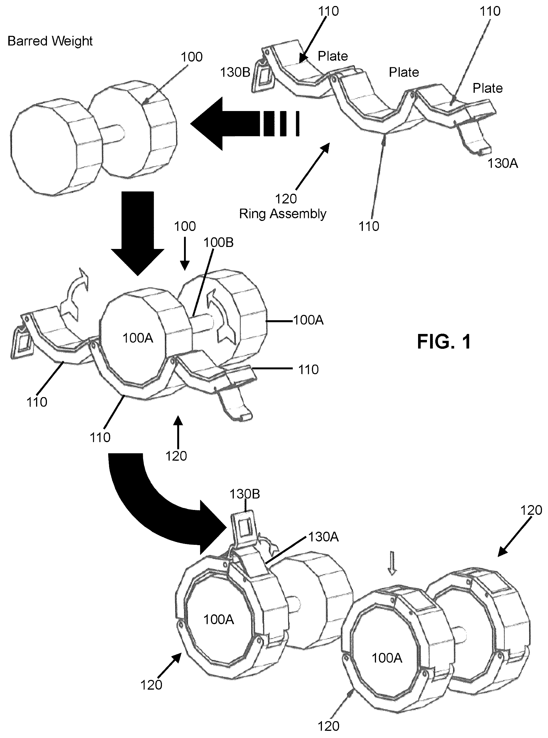
is pictorial illustration of the incremental increasing of a weight characteristic of a bar weight with a collar of hinged plates;
is a side view of the collar of hinged plates of secured through the operation of a latch;
is a perspective view of an aspect of the collar of hinged plates of , including a frictional insert having an exterior circular shape and an interior circular shape.
is a perspective view of an aspect of the collar of hinged plates of , including a frictional insert having an exterior polygonal shape and an interior circular shape.
is a perspective view of an aspect of the collar of hinged plates of , including a frictional insert having an exterior circular shape and an interior polygonal shape.
is a side view of an aspect of the collar of hinged plates of , including separable spring biased fixed inserts for each of the hinged plates.
is a perspective view of an aspect of the collar of hinged plates of with at least one of the hinged plates including a floor support.
DETAILED DESCRIPTION OF THE INVENTION
Embodiments of the invention provide for a collar of hinged plates adapted to provide an adaptive weight belt retrofitting a bar weight. In accordance with an embodiment of the invention, the collar includes several hinged plates, each formed of solid metal such as steel or cast iron. The hinged plates are hinged to one another with a hinge pin, for example, at respective distal and proximal ends of the hinged plates with one of the plates having a hinge connection to an adjacent plate at a proximal end and a portion of a latch at a distal end, and another of the plates having a hinge connection to an adjacent plate at a distal end and a complimentary portion of the latch at the proximal end. In this way, the latch secures the two plates together forming a collar of hinged plates. In operation, the latch secures the two plates together forming the collar and friction fitting the collar to an exterior surface of a weight portion of a barred weight so as to incrementally increase the weight of the barred weight according to the cumulative weight of the plates of the collar while ensuring the collar does not slip from the weight portion of the barred weight.
In further illustration, is pictorial illustration of the incremental increasing of a weight characteristic of a bar weight with a collar of hinged plates. As shown in , a ring assembly 120 of different plates 110 , each of solid metal, are hinged to one another in sequence. One of the plates 110 at a distal end includes a keeper 130 A and another of the plates 110 at a proximal end includes a hook 130 B, the keeper 130 A and the hook 130 B forming a latch. In this way, when the keeper 130 A engages the hook 130 B around an exterior surface of the weight portion 100 A of a barred weight 100 of two weight portions 100 A coupled to one another by a bar 100 B, the resulting ring assembly 120 forms a collar of hinged plates secured to the exterior surface of the weight portion 100 A. The collar of hinged plates augments the weight of the weight portion 120 A by the cumulative weight of the plates 110 of the ring assembly 120 .
In more particular illustration, is a side view of the collar of hinged plates of secured through the operation of a latch. As shown in , different plates 210 are hinged to one another in sequence with a common hinge pin 260 . The plates 210 in the example shown in , when formed into the collar 220 , have an interior portion of a polygonal shape matching a polygonal shape of a circumferential surface of the weight portion of a barred weight. To that end, each of the plates 210 includes a polygonal segment of at least three faces with each distal one of the faces has an identical angle of intersection to an adjacent one of the faces as each other distal one of the faces. One of the plates 210 at one end of the sequence of plates 210 has a latching portion 230 A with a keeper 250 adapted to mate with a hook 240 of a complementary latching portion 230 B of another of the plates 210 positioned at an opposite end of the sequence of plates 210 so as to form the collar 220 when the keeper 250 engages the hook 240 and is carried forth to a maximum travel distance drawing the hook 240 and the keeper 250 past the center of 230 B hinge pin allowing the keeper 250 to be secured.
In an alternative aspect of the embodiment, the collar 220 can have a circular shape with each of the plates including, not a multifaced polygonal profile, but a circular profile with a circular segment having a central angle matching a central angle of the circumferential surface of the weight of the barred weight to which the collar 220 is to be affixed. In this regard, is a perspective view of an aspect of a collar of hinged plates similar to that of in which each of the plates of collar 320 has a circular profile with a circular segment having a central angle matching a central angle of the circumferential surface of the weight portion 300 A of the barred weight to which the collar is to be affixed.
Notably, as shown in , the collar can support a frictional insert 370 fixed to the interior surface of the plates when secured into the collar 320 . The frictional insert 370 can include different profiles adapted to match the profile of an exterior surface of the weight portion 300 A of a barred weight. For instance, as shown in , the frictional insert 370 has an exterior circular shape 380 B matching the interior profile of the collar 320 , and an interior circular shape 380 A matching the exterior profile of the weight portion 300 A of the barred weight. The shape of the frictional insert 370 , though can vary in other aspects of the embodiment.
To that end is a perspective view of an aspect of the collar of hinged plates of , including a frictional insert having an exterior polygonal shape and an interior circular shape. As shown in , a frictional insert 470 has an exterior polygonal shape 480 B matching the shape of the interior portion of the collar 420 , and an interior circular shape 480 A matching the exterior profile of the weight portion 400 A of the barred weight. Conversely, as shown in , a frictional insert 570 has an exterior circular shape 580 B matching the shape of the interior portion of the collar 520 , and an interior polygonal shape 580 A matching the exterior profile of the weight portion 500 A of the barred weight.
In an alternative aspect of the embodiment, each hinged plate in the collar can have a corresponding segment of a frictional insert. More particularly, is a side view of an aspect of the collar of hinged plates of , including separable spring biased frictional inserts for each of the hinged plates. As shown in , each hinged plate of the collar 620 has a corresponding frictional insert segment 680 B with a shape confirming to an interior portion of the corresponding frictional insert. The frictional insert segment 680 B can be a steel or cast iron plate secured at an exterior surface to an interior surface of the corresponding hinged plate by a spring 680 A, 680 D (spring 680 A in a compressed state and spring 680 D in an extended state) biasing the plate 680 B outwardly away from the interior surface of the corresponding hinged plate. A frictional pad 680 C such as a rubber pad, polyethylene pad, fabric pad or other such fiction bearing material, is secured to an interior portion of the plate 680 B. In this way, when the collar 620 envelops the exterior surface of the weight portion 600 A of the barred weight, each frictional insert segment 680 B through the frictional pad 680 C separately engages a counterpart exterior surface of the weight portion 600 A of the barred weight.
Finally, in even yet another aspect of the embodiment, one of the hinged plates can include a floor support that includes, by way of non-limiting example, an integrated trapezoidal foot 720 A, 720 B extending from a surface of the one of the hinged plates. As shown in , the floor support 720 A, 720 B be a unitary part of one of the hinged plates providing a flat base with opposing feet to stabilize the collar when the collar engages the exterior surface of the barred weight and rests on a flat surface.
The terminology used herein is for the purpose of describing particular embodiments only and is not intended to be limiting of the invention. As used herein, the singular forms “a”, “an” and “the” are intended to include the plural forms as well, unless the context clearly indicates otherwise. It will be further understood that the terms “include”, “includes”, and/or “including,” when used in this specification, specify the presence of stated features, elements, and/or components, but do not preclude the presence or addition of one or more other features, elements, components, and/or groups thereof.
The corresponding structures, materials, acts, and equivalents of all means or step plus function elements in the claims below are intended to include any structure, material, or act for performing the function in combination with other claimed elements as specifically claimed. The description of the present invention has been presented for purposes of illustration and description but is not intended to be exhaustive or limited to the invention in the form disclosed. Many modifications and variations will be apparent to those of ordinary skill in the art without departing from the scope and spirit of the invention. The embodiment was chosen and described in order to best explain the principles of the invention and the practical application, and to enable others of ordinary skill in the art to understand the invention for various embodiments with various modifications as are suited to the particular use contemplated.
Having thus described the invention of the present application in detail and by reference to embodiments thereof, it will be apparent that modifications and variations are possible without departing from the scope of the invention defined in the appended claims as follows:
Figures (4)
Citations
This patent cites (13)
- US4971318
- US7128667
- US8900104
- US10625136
- US11247093
- US11324986
- US11666793
- US2005/0075221
- US2009/0205106
- US2013/0316880
- US2017/0304671
- US2017/0361148
- US2020/0094100