Abstract
Neural activity in the brain arising from a stimulus is monitored. A stimulus is applied to a target structure of the brain and a neural measurement is obtained from at least one electrode implanted in contact with the target structure. The neural measurement is configured to capture a measure of any late response arising in the target structure, typically being a neural response arising after conclusion of an ECAP, such as in the period 1.5-10 ms after stimulus onset. The late response(s) can be a useful biomarker such as of therapeutic ranges of deep brain stimulation, disease progression, medication efficacy, and intra-operative changes.
Claims (20)
1. A method of stimulating a brain, the method comprising: applying, by a control unit, a plurality of stimuli to a target structure of the brain with at least one implantable electrode in contact with the target structure, where stimuli in the plurality of stimuli are delivered at varied amplitudes; obtaining, by the control unit, a plurality of neural measurements from the at least one implantable electrode in contact with the target structure, each neural measurement configured to capture a measure of any late response arising in the target structure resulting from a corresponding stimulus in the plurality of stimuli; and identifying, by the control unit, a therapeutic transition point associated with the late response by recording and processing the plurality of neural measurements that each capture a respective measure of the late response arising in the target structure from a respective stimulus of the plurality of stimuli, wherein the therapeutic transition point comprises a therapeutic transition stimulation amplitude of the plurality of stimuli at, or around which, a peak of the late response is delayed relative to respective late response peaks corresponding to stimuli having stimulation amplitudes that are lower than the therapeutic transition stimulation amplitude; or a growth curve of the late response changes, and applying, by the control unit, subsequent stimuli to the target structure at amplitudes at or greater than the therapeutic transition stimulation amplitude.
16. An implantable device for stimulating neural activity in a brain, the device comprising: a control unit; a stimulus source powered by a battery and controlled by the control unit to provide a plurality of stimuli from one or more electrodes to a target structure of the brain, where stimuli in the plurality of stimuli are delivered at varied amplitudes; measurement circuitry for obtaining a plurality of neural measurements from the one or more electrodes in contact with the target structure, the neural measurement configured to capture a measure of any late response arising in the target structure resulting from a corresponding stimulus in the plurality of stimuli; wherein the control unit is configured to identify a therapeutic transition point associated with the late response by recording and processing the plurality of neural measurements that each capture a respective measure of the late response arising in the target structure from a respective stimulus of the plurality of stimuli, wherein the therapeutic transition point comprises a therapeutic transition stimulation amplitude of the plurality of stimuli at, or around which, a peak of the late response is delayed relative to respective late response peaks corresponding to stimuli having stimulation amplitudes that are lower than the therapeutic transition amplitude; or a growth curve of the measured late response changes; and the control unit is further configured to apply subsequent stimuli to the target structure at amplitudes at or greater than the therapeutic transition stimulation amplitude.
20. A non-transitory computer readable medium for stimulating neural activity in a brain, comprising instructions which, when executed by one or more processors, causes performance of the following: applying, by a control unit, a plurality of stimuli to a target structure of the brain with at least one implantable electrode in contact with the target structure, where stimuli in the plurality of stimuli are delivered at varied amplitudes; obtaining, by the control unit, a plurality of neural measurements from the at least one implantable electrode in contact with the target structure, each neural measurement configured to capture a measure of any late response arising in the target structure resulting from a corresponding stimulus in the plurality of stimuli; and identifying, by the control unit, a therapeutic transition point associated with the late response by recording and processing the plurality of neural measurements that each capture a respective measure of the late response arising in the target structure from a respective stimulus of the plurality of stimuli, wherein the therapeutic transition point comprises a therapeutic transition stimulation amplitude of the plurality of stimuli at, or around which, a peak of the late response is delayed relative to respective late response peaks corresponding to stimuli having stimulation amplitudes that are lower than the therapeutic transition amplitude; or a growth curve of the measured late response changes, and applying, by the control unit, subsequent stimuli to the target structure at amplitudes at or greater than the therapeutic transition stimulation amplitude.
Show 17 dependent claims
2. The method of claim 1 further comprising: obtaining a plurality of neural measurements of evoked compound action potentials (ECAPs) arising from respective ones of the plurality of stimuli; setting a target ECAP amplitude for the ECAPs arising from the plurality of stimuli, the target ECAP amplitude comprising an ECAP amplitude arising from application of the stimuli at or around the therapeutic transition stimulation amplitude; and adjusting at least one stimulus subsequent to the plurality of stimuli giving rise to the obtained plurality of neural measurements of ECAPs, the adjusting being based on the target ECAP amplitude.
3. The method of claim 1 , further comprising: obtaining a neural measurement of an evoked compound action potential (ECAP) arising from one of the plurality of stimuli; determining an ECAP parameter comprising at least one of presence, amplitude, morphology, and latency of the ECAP; and adjusting at least one stimulus subsequent to said one of the plurality of stimuli giving rise to the obtained neural measurement of the ECAP, the adjusting based on the ECAP parameter.
4. The method of claim 1 , wherein identifying the therapeutic transition point is based on a late response growth curve of the respective late responses.
5. The method of claim 1 wherein each of the plurality of neural measurements are obtained in a respective time period beginning 2-3 ms after onset of the respective one of the plurality of stimuli.
6. The method of claim 1 wherein each of the plurality of neural measurements are obtained in a respective time period ending in a range of 5-10 ms after onset of the respective one of the plurality of stimuli.
7. The method of claim 1 wherein each of the plurality of neural measurements are obtained in a respective time period ending in a range of 5.5-8 ms after onset of the respective one of the plurality of stimuli.
8. The method of claim 1 wherein each of the plurality of neural measurements are obtained in a respective time period ending in a range of 6.5-7.5 ms after onset of the respective one of the plurality of stimuli.
9. The method of claim 1 wherein each of the plurality of neural measurements are obtained in a respective time period configured to also capture a measure of any compound action potential arising directly from the respective stimulus, prior to the respective late response.
10. The method of claim 1 further comprising comparing a characteristic of at least one of the measures of the late response to a healthy range in order to diagnose a disease state.
11. The method of claim 1 further comprising, upon determining a presence of a first late response from a first neural measurement of the plurality of neural measurements, monitoring subsequent neural measurements of the plurality of neural measurements for changes in a respective measure of a characteristic of the respective late responses over time, in order to diagnose a disease state.
12. The method of claim 1 wherein the applying of the subsequent stimuli is to regulate neural activity in the brain to a target level or target profile.
13. The method of claim 1 , further comprising adjusting a stimulation paradigm in response to the measure of the late response.
14. The method of claim 1 further comprising monitoring the plurality of neural measurements to assess beta band oscillations influencing the neural measurements.
15. The method of claim 2 , wherein the method further comprises the step of monitoring changes in the therapeutic transition point, and adjusting, by the control unit, application of subsequent stimuli in response to the monitored changes in the therapeutic transition point.
17. The device of claim 16 , wherein the control unit is further configured to: obtain a plurality of neural measurements of evoked compound action potentials (ECAPs) arising from respective ones of the plurality of stimuli; set a target ECAP amplitude for the ECAPs arising from the plurality of stimuli, the target ECAP amplitude comprising an ECAP amplitude arising from application of the stimuli at or around the therapeutic transition stimulation amplitude; and adjust at least one stimulus subsequent to the plurality of stimuli giving rise to the obtained plurality of neural measurements of ECAPs, the adjustment being based on the target ECAP amplitude.
18. The device of claim 16 , wherein the control unit is further configured to: obtain a neural measurement of an evoked compound action potential (ECAP) arising from one of the plurality of stimuli; determine an ECAP parameter comprising at least one of presence, amplitude, morphology, and latency of the ECAP; and adjust at least one stimulus subsequent to said one of the plurality of stimuli giving rise to the obtained neural measurement of the ECAP, the adjustment based on the ECAP parameter.
19. The device of claim 17 , wherein the control unit is further configured to monitor changes in the therapeutic transition point, and adjust application of subsequent stimuli in response to the monitored changes in the therapeutic transition point.
Full Description
Show full text →
CROSS-REFERENCE TO RELATED APPLICATIONS
This application is a continuation of U.S. patent application Ser. No. 15/036,395 filed on May 12, 2016, which is a national stage of PCT Application No. PCT/AU2014/001049 filed Nov. 14, 2014, which claims the benefit of Australian Provisional Patent Application No. 2013904434 filed Nov. 15, 2013, Australian Provisional Patent Application No. 2014901076 filed Mar. 26, 2014, and Australian Provisional Patent Application No. 2014904271 filed Oct. 24, 2014, the disclosures of which are incorporated herein by reference in their entireties.
TECHNICAL FIELD
The present invention relates to neural modulation in the brain, and in particular relates to a method for monitoring neural measurements of activity in the brain arising from stimulation in order to monitor therapeutic effect of the stimulation, or to monitor therapeutic effect of medicine, or to monitor disease state.
BACKGROUND OF THE INVENTION
Neuromodulation involves applying an electric stimulus to biological tissue in order to produce a therapeutic effect. Neuromodulation can be non-invasive such as by transcutaneous electrical nerve stimulation (TENS), transcranial magnetic stimulation (TMS), or highly invasive when requiring the implantation of one or more electrodes and a controlling stimulator as in the case of deep brain stimulation (DBS). DBS has become the most effective treatment for late stage Parkinson's disease, but is a highly invasive therapy requiring the implantations of two leads deep into subcortical nuclei and connection to one or more pulse generators implanted in the chest. Many DBS electrode target structures have been studied to treat a wide variety of diseases and the preferred location of the electrode varies depending on the disease that is being treated. In the case of Parkinson's disease, the preferred targets are the internal segment of the globus pallidus (GPi) and the subthalamic nucleus (STN). The GPi has also been targeted for Huntington's disease and Tourette's syndrome, the nucleus accumbens has been targeted for chronic depression and alcohol dependence, and the fornix is being trialed for Alzheimer's disease.
Parkinson's disease is a degenerative disorder affecting dopamine-releasing cells in the substantia nigra. Many theories describing the functioning of the basal ganglia and how this degeneration relates to Parkinson's disease have been proposed, however all such theories have significant inadequacies in describing all aspects of Parkinson's disease, and understanding the mechanisms of DBS remains the focus of considerable research effort.
A significant reason for the lack of understanding about the mechanisms of DBS and the basal ganglia is the difficulty of measuring the direct responses of the nervous tissue to stimulation. Most of the findings are based on single-cell measurements on efferent structures and, until recently, it was impossible to adequately measure the direct compound response of the target structures because when recording close to the stimulation site, large artefacts (electrical and electrode artefacts) tend to mask the tissue response.
Any discussion of documents, acts, materials, devices, articles or the like which has been included in the present specification is solely for the purpose of providing a context for the present invention. It is not to be taken as an admission that any or all of these matters form part of the prior art base or were common general knowledge in the field relevant to the present invention as it existed before the priority date of each claim of this application.
Throughout this specification the word “comprise”, or variations such as “comprises” or “comprising”, will be understood to imply the inclusion of a stated element, integer or step, or group of elements, integers or steps, but not the exclusion of any other element, integer or step, or group of elements, integers or steps.
In this specification, a statement that an element may be “at least one of” a list of options is to be understood that the element may be any one of the listed options, or may be any combination of two or more of the listed options.
SUMMARY OF THE INVENTION
According to a first aspect the present invention provides a method of monitoring neural activity in the brain arising from a stimulus, the method comprising:
•
• applying a stimulus to a target structure of the brain; and • obtaining a neural measurement from at least one electrode implanted in contact with the target structure, the neural measurement configured to capture a measure of any late response arising in the target structure.
According to a second aspect the present invention provides an implantable device for monitoring neural activity in the brain arising from a stimulus, the device comprising:
•
• a stimulus source for providing a stimulus to be delivered from one or more stimulus electrodes to a target structure of the brain; and • measurement circuitry for obtaining a neural measurement from a sense electrode in contact with the target structure, the neural measurement configured to capture a measure of any late response arising in the target structure.
The measure of the late response in some embodiments comprises a record of substantially the entire duration of the late response. In the case of the subthalamic nucleus the measure of the late response in some embodiments may encompass a time period beginning 1-5 ms after the stimulus onset, more preferably beginning 1.5-4 ms after the stimulus, more preferably beginning 2-3 ms after the stimulus. In the case of the subthalamic nucleus the measure of the late response in some embodiments may encompass a time period ending 5-10 ms after the stimulus, more preferably ending 5.5-8 ms after the stimulus, more preferably ending 6.5-7.5 ms after the stimulus onset. It is to be noted that the late response as referred to herein may comprise multiple neural responses, so that the measure of the late response may comprise multiple maxima and minima.
The neural measurement in some embodiments is configured to also capture a measure of any compound action potential (CAP) arising directly from the stimulus, prior to the late response. In such embodiments a period encompassing the late response may be defined by reference to one or more features of the CAP, such as the CAP P 2 peak, rather than defining such period relative to the stimulus.
The neural measurement is preferably obtained in accordance with the teaching of International Patent Publication No. WO2012/155183 by the present applicant, the content of which is incorporated herein by reference.
According to another aspect, the present invention provides a non-transitory computer readable medium for monitoring neural activity in the brain arising from a stimulus, comprising instructions which, when executed by one or more processors, causes performance of the following:
•
• applying a stimulus to a target structure of the brain; and • obtaining a neural measurement from at least one electrode implanted in contact with the target structure, the neural measurement configured to capture a measure of any late response arising in the target structure.
By capturing a measure of any late response arising in the target structure some embodiments of the present invention may deliver a diagnostic method. The presence, amplitude, morphology, and/or latency of the late response may be compared to healthy ranges and/or monitored for changes over time in order to diagnose a disease state. The method of the invention may be applied in some embodiments in order to determine a therapeutic effect of the stimulation, determine a therapeutic effect of medicine, and/or to monitor disease state. A therapeutic response may subsequently be ordered, requested and/or administered based on the diagnosis.
Some embodiments of the present invention may be applied specifically in relation to stimulation of the subthalamic nucleus. However alternative embodiments may be applied in relation to the application of stimuli to other portions of the brain in which an early neural response arises in a linear manner in response to the stimulus, and in which a non-linear late response subsequently arises which may be separately monitored to the early response.
The therapeutic effect determined from the late response may be used in some embodiments in order to regulate neural activity to a target level or target profile.
The therapeutic effect determined from the late response may be used in some other embodiments as an intra-operative tool to assist surgeons to implant an electrode at an ideal location or orientation. For example by exploring a stimulus parameter space repeatedly throughout implantation, while watching the late response, to find a location, orientation and stimulus paradigm which is therapeutic and of lowest power consumption, and/or to monitor for adverse side effects. In the case of epilepsy a neural region of heightened excitability, as indicated by early onset of the late response as compared to other regions, may be identified as a likely focus of focal seizures.
In still further embodiments, the late response may reveal an efficacy of a medication taken by the user, and may be used to adjust a stimulation paradigm over time as medicine wears off. Moreover, a reduction in efficacy of a medicine over time, or the monitoring of progression of a disease over time, such as over weeks, months or years, may be monitored by some embodiments of the present invention.
It is to be understood that the at least one electrode from which the neural measurement is obtained is implanted in electrical contact with the target structure but not necessarily in physical contact with the target structure. For example where the stimulus is applied to the STN, the at least one electrode from which the neural measurement is obtained may be implanted partly or wholly within the zona incerta or in another structure near the STN.
Some embodiments of the present invention may further provide for monitoring of local field periodic signals by reference to the late response. For example a peak-to-peak amplitude of the late response may be modulated by the heartbeat of the patient and thus the deep brain stimulator may in some embodiments be configured to monitor the patient's heart rate by reference to 0.5-3 Hz modulations of the peak to peak amplitude of a plurality of measurements of the late response, thus eliminating the need to provide a separate heart rate monitor, and without the need to interrupt the stimulation. These and/or other embodiments may further assess beta-band oscillations influencing the measurement(s) of the late response, which can be one of the main observable electrophysiological changes in PD.
BRIEF DESCRIPTION OF THE DRAWINGS
An example of the invention will now be described with reference to the accompanying drawings, in which:
illustrates a simulated single fibre action potential profile;
a illustrates evoked compound action potentials (ECAPs) measured on electrodes at close range to a stimulus site, and b illustrates the biphasic stimulus delivered;
shows the growth curves of the P 2 -N 1 amplitude for a truncated and non-truncated ECAP;
illustrates the late responses for various stimulus currents;
illustrates the late response progressing non-linearly through three different states;
illustrates the latency between the N 1 peak and the P 2 peak, on each of electrodes 3 and 4 ;
shows the growth curve of the second peak of the late responses, relative to increasing stimulus current, measured on each of electrodes 3 and 4 ;
is a schematic diagram of a deep brain stimulator with local feedback;
is a schematic diagram of a deep brain stimulator with local feedback via simple tuning mechanism;
illustrates a hybrid feedback system;
a and 11 b illustrate that under medication the amplitude of the ECAPs is markedly decreased;
illustrates late responses for various stimulation currents in a patient on and off medication,
illustrates neural response measurements obtained from a patient being treated with deep brain stimulation of the ventral-intermediate nucleus of the thalamus;
illustrates data obtained from electrodes 3 and 4 in the left hemisphere of a patient treated with STN DBS, with a showing the neural response measurements from each electrode, b being a plot of late response latency against stimulus current, and c being a plot of late response amplitude against stimulus current;
illustrates data obtained from the same patient as , from electrodes 7 and 8 in the right hemisphere which was atrophied, with a showing the neural response measurements from each electrode, b being a plot of late response latency against stimulus current, and c being a plot of late response amplitude against stimulus current;
illustrates data obtained from the same patient as , from electrodes 5 and 6 in the right hemisphere, with a showing the neural response measurements from each electrode, and b being a plot of late response latency against stimulus current;
a illustrates late responses recorded in healthy tissue in the same patient as , for a constant stimulus amplitude but varying frequency, and b is a plot of the latency of one of the late response peaks against stimulus frequency; and
illustrates late response measurements obtained in respect of another patient receiving STN DBS.
DESCRIPTION OF THE PREFERRED EMBODIMENTS
The following describes a number of embodiments utilising measurement of the compound action potential arising from stimulation of the subthalamic nucleus (STN), and a number of applications that these measurements may have such as for improving the therapy. While the following embodiments relate to STN stimulation for Parkinson's disease, it is to be understood that other embodiments of the invention may be applied to other applications of deep brain stimulation.
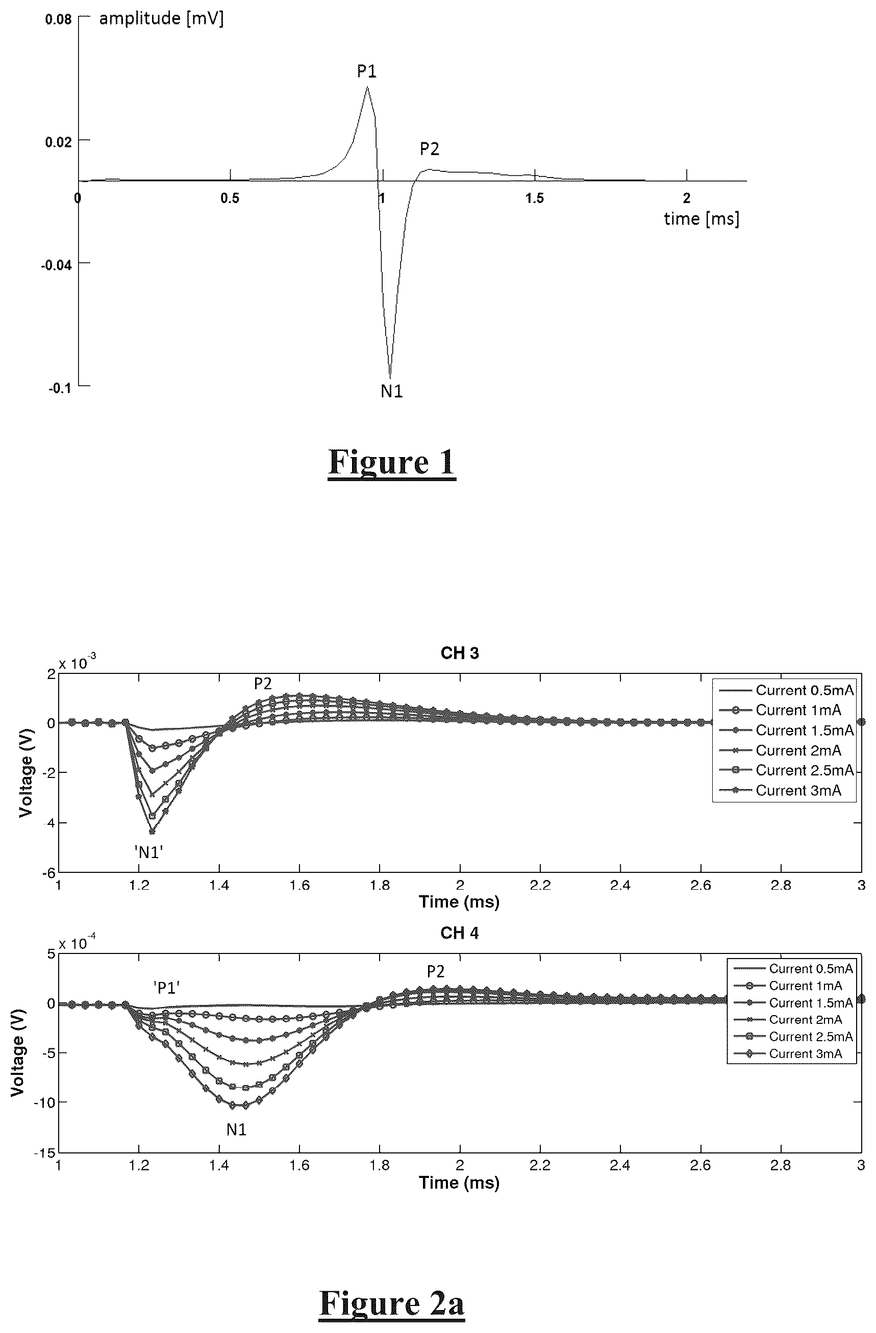
The combined response of nervous tissue to electrical stimulation usually takes the form of an evoked compound action potential (ECAP). For illustrative purposes, shows the evoked action potential arising when simulating a single fibre from a spinal cord model. The three peaks characteristic of the action potential, respectively referred to as the P 1 , N 1 and P 2 peaks, are clearly visible. The typical response of multiple fibres together, namely the compound action potential (CAP), is usually smoother and more spread-out then the single fibre action potential profile shown in , but the 3 characteristic peaks are nevertheless still present in a CAP.
The details of the measurement technique used in the present embodiments are described in WO2012/155183, and its application in a feedback loop are described in WO2012/155188 by the present applicant, the content of which is incorporated herein by reference.
When seeking to measure neural responses arising from a stimulus in a target structure in the brain, as in the case of DBS, it is noted that this application necessitates very short distances between the stimulating site and the recording site, for example no more than about 5 to 9 millimetres for the STN, and in the present embodiment electrode 3 is positioned about 1.5 mm away from the stimulus site, this being the inter electrode spacing. Considering the propagation speed, and the necessity for a certain minimum blanking period during which the measurement amplifiers must be disconnected from the electrodes to avoid artefact, the ECAPs measured on electrodes at this range are truncated as seen in both plots of a in the period prior to about 1.2 ms after the initiation of the stimulus in both plots of (note that the stimulus is not initiated at 1=0, the nature of the measurement setup causes some delay at the beginning of the measured trace prior to the first stimulus pulse). It is however possible to use the remaining signal, after about t=1.2 ms, i.e. from about 0.3 ms after completion of the stimulus, for analysis and feedback purposes in a similar way the full ECAP would be used if it were available.
present recordings of evoked action potentials (ECAPs) and Late Responses (LRs) measured intraoperatively in the subthalamic nucleus (STN) of patients undergoing the implantation of deep brain stimulators. In these figures the stimulus onset occurred at about 0.79 ms after t=0. a shows ECAPs obtained from biphasic bipolar stimulation at 130 Hz and 90 us pulse width on electrodes 1 and 2 of a DBS electrode array (denoted 201 and 202 , respectively, in b ), and measured on electrode 3 (top plot) and electrode 4 (bottom plot of a ) of the array (denoted 203 and 204 , respectively, in b ). The 3-peak response resembles ECAPs observed during spinal cord stimulation. The blanking period of the measurement device masks the first P 1 peak on electrode 3 , the electrode closest to the stimulus site. Also, peak N 1 is partially truncated. The upper plot in a shows measured ECAPs on electrode 3 , close to the stimulus site, at varying amplitudes of stimulus current. The signal is several millivolts strong for 3.5 mA stimulation and propagates away from the stimulus site. The lower plot in a shows measured ECAPs on electrode 4 , a small distance further from the stimulus site as compared to electrode 3 , at the same varying amplitudes of stimulus current. Peak P 1 again is removed by truncation but N 1 is more intact. While Channel 3 suffers more truncation, it receives signals of about 4 times greater amplitude than channel 4 , noting the different y-axis scales in the two plots. a shows that the compound action potential evoked by the stimulus in the STN rises with stimulus current, and concludes within about 1.7 ms of onset of the stimulus as the action potentials propagate away from the stimulus site.
b illustrates the biphasic stimulus delivered on electrode 1 ( 201 ) and electrode 2 ( 202 ) with an alternating polarity pattern in which the polarity of the first pulse in a biphasic stimulus changes with each impulse.
shows the growth curves of the P 2 -N 1 amplitude for a truncated and non-truncated peaks in the same patient. This illustrates that the linearity is well preserved which allows for an easy calibration and feedback design to control the ECAP amplitude. Despite the truncation in channel 3 , the electrode closer to the stimulus site displays larger responses when measured as |P 2 -N 1 | as compared to electrode 4 , further away from the stimulus site. Thus, despite the truncation, the general characteristics of fading and smearing as the response moves away from the stimulus are preserved. For the sake of clarity, the text will use the term “ECAP” to refer to both the complete ECAP and the truncated one. In the case of the truncated ECAP, the N 1 -P 2 amplitude is taken as shown on a.
shows the truncated ECAPs measured on two separate channels for various stimulation intensities. It can be seen that only channel 4 displays the full N 1 peak. Despite the truncation on channel 3 only, it has been shown that the |N 1 -P 2 | amplitudes both have linear growth curves with some threshold behaviour at very low stimulation intensities
shows growth curves of the |N 1 -P 2 | amplitude for various stimulation currents. CH 3 is the electrode closest to the stimulus site, in which the N 1 peak is truncated, and CH 4 is the electrode furthest away from the stimulus site with an intact N 1 peak. The growth curve displays a threshold behaviour below 0.5 mA stimulation and transitions smoothly to a linear regime. On E 3 , the slope is 1.7 mV/mA (R 2 >0.99) and on E 4 the slope is 0.37 mV/mA (R 2 >0.99) for stimulus currents 1.5 mA and above.
In addition to the ECAP arising directly from the stimulus and concluding within about 1.7 ms of the stimulus, as shown in a , the present invention further recognises that a late response follows the ECAPs, and carries important information. Without wishing to be limited by theory, it is nevertheless noted that the late responses (LR), unlike ECAPs (also referred to herein as early responses), are not the direct response of the tissue but rather appear to be a systems response from the cortex and other subcortical structures projecting back into the STN. Irrespective of mechanism the present invention recognises the existence of the late response, and a range of uses and applications arising from its measurement.
The late responses are typically of much smaller amplitude than the early ECAP, and typically do not have a linear growth curve. At 130 Hz stimulation (a standard frequency for maximum efficacy), two late responses can be observed, one occurring shortly after the end of the early response, and one occurring roughly 2-3 milliseconds after the first. The present specification when describing a late response in the singular may thus encompass more than one response manifesting in the neural measurement, after the ECAP.
Some embodiments of the present invention further recognise that, in the case of the STN, as the stimulation current is increased the late response progresses non-linearly through three different states as shown in :
•
• a. The subthreshold state 502 when the stimulation current is below about 0.6 mA, in which only a very small late response or no response at all occurs; • b. The non-therapeutic state 504 when the stimulation current is between about 0.6 mA and about 2.5 mA, in which a late response can be clearly observed between 4.5-7 ms on the time scale of , but in which the stimulation does not yet have therapeutic effects for the patient; and • c. The therapeutic state 506 in which the stimulation current is above about 2.5 mA, which corresponds to therapeutic levels of stimulation. Thus, the transitions from the subthreshold state to the non-therapeutic state and then to the therapeutic state are abrupt in the STN for this patient and marked boundaries can be observed in when the stimulus current is increased past the two transition points. Similar non-linear states of the late response may be similarly illustrative and useful in other target structures in the brain.
The transition from the non-therapeutic state to the therapeutic state is characterised by a marked shift in time of around 1.5 ms of the peak of the second late response with respect to its location in time in the non-therapeutic state (see and ). illustrates the late responses for various stimulus currents. The boldface traces each represent one of the states the system can be in. The late responses are an order of magnitude smaller than the ECAPs and peak roughly 1 ms and 3 ms after the end of the ECAP. For example in the lower plot of the second late response peaks at about 5.5 ms when the stimulation current is 1.5 mA, but peaks substantially later at about 7 ms when the stimulation current is 3.5 mA. Thus, therapeutic stimulation is correlated with a shift in time of the late responses of around 0.5-1.5 ms. The first late response also shifts slightly (from about 3 ms to about 3.5 ms) when the transition is made, this shift is however smaller and therefore may be harder to use in a clinical setting and noisy environment. Thus, even though the shift in the first late response could be used in a similar way than the shift in the second late response, the second part of the late response presents a more distinguishable characteristic and is thus the focus of the present embodiments. Nevertheless other embodiments could additionally or alternatively address the first part of the late response.
illustrates the latency between the N 1 peak and the P 2 peak, on each of electrodes 3 and 4 . This shows that the ECAPs of a do not spread out with increasing stimulus currents. The variations of E 4 are well within the sampling error (f sample =30 KHz). On E 3 the variation is mainly due to truncation of the signal and artefact.
Unlike the early responses which as seen in display a linear growth curve without plateau in the observed range (although a plateau is likely to occur at higher stimulus intensities), the late responses' amplitudes plateau very quickly. shows the growth curve of the second peak of the late responses, relative to increasing stimulus current, measured on each of electrodes 3 and 4 . Unlike the linearly growing ECAPs ( ), the growth curve of the late responses in levels off quickly and seems to be state-dependent. The late response peak on E 4 decreases in amplitude when the therapeutic state is reached and grows again within the new state. This is more conspicuous on E 4 than on E 3 which is closer to the stimulation site, where the size of the evoked response might mask some of the smaller responses and is likely to have decreased excitability shortly after the early response.
The neural measurements encompassing the period containing the late response(s) thus show that the responses are made up of two distinct parts: one being the ECAPs from the surrounding tissue and the second being the late responses, which may be cortical potentials projecting back into the basal ganglia. The preceding further establishes that the late responses undergo three distinct states when the stimulation current is increased: the subthreshold state where no response occurs, the non-therapeutic state in which a clear response is present but which has no therapeutic effect for the patient, and the therapeutic state which coincides with the neurologist's assessment of therapeutic levels of stimulation.
The identification of these distinct states could in turn in some embodiments be used to ease the design of feedback-enabled deep brain stimulators and provide a quantifiable way to assess the efficacy of deep brain stimulation in the surgical theatre and throughout the therapy.
The present invention thus recognises that by taking a measurement and monitoring for such a late response, a range of observations may be made. A number of such embodiments of the invention will now be discussed. In each of the systems presented below, each electrode can either be stimulating or recording. Each device will contain one or multiple leads with 2 or more electrodes on each lead. The stimulation and recording can be carried out on any given set of electrodes on each lead. Each of these systems will comprise the leads, a controllable stimulator and a processing unit that will process the recorded information and set the control parameters accordingly.
One embodiment involves parameter adjustment for DBS for Parkinson's. It is noted from that the amplitude growth of the ECAP is linear over a range of currents. The slope of growth, and the threshold at which an ECAP is first detected at smallest stimulus current, both provide a measure of the excitability of the DBS structure which is being stimulated, as well as providing long term and continuous information regarding the neurological state of the target being stimulated.
This embodiment thus recognises that measurement of the ECAP amplitudes and shapes as a function of stimulation parameters provides useful information for parameter programing. Measurement of the strength duration curve by measuring the ECAP threshold at a range of pulse widths allows determination of the chronaxie and rehobase for the recruited neurons. From this, the most efficient stimulation pulse width and current can be determined. Stimulating with efficient parameters has the beneficial effect of lowering the power consumption and allowing the construction of smaller devices.
The neural response measurements can be collected and stored in the implant for later downloading. The downloading and access to the data can be achieved via a number of means, for example the clinician can download information at the time of routine follow-up. Information can be downloaded when the patient charges their system of via wireless radio (preferably MCS band) periodically. The data can be transferred to centralised databases, etc.
Another embodiment provides a deep brain stimulator with local feedback. The neural response measurement can be used in a closed-loop feedback system. is a schematic diagram of such a feedback system using only 3 electrodes and a reference electrode for the amplifier. Once the optimal stimulation settings have been assessed, the stimulus is controlled in a way to maintain the response at a constant amplitude. This will eliminate all local effects such as heart beat and small changes in the response due to temporary or chronic metabolic changes. The responses are monitored, processed, and the stimulus adapted accordingly.
A plethora of causes can change the response of the tissue to stimulation, and may be addressed by the embodiment of , including:
•
• a. Adaptation • b. Changes in electrode micro environment co-incident with the heartbeat • c. A worsening of the state of the disease • d. The course of medication intake • e. The current overall state of the patient (sleep, rest, movement, etc.)
shows an example of bipolar stimulation, in which both the stimulation and ground electrode are part of the same electrode lead. However a monopolar stimulus, in which the ground electrode is elsewhere such as on the case of the implant, is also an option in other embodiments.
In another embodiment there is provided a device to determine the efficacy of the therapy and the best stimulation settings. As noted in the preceding, the neural measurements consist of early responses (1-3 ms) and much smaller late responses (3-7 ms), and there are marked changes in the late response characteristics. For the sake of simplicity, the term “delay” when referring to the late responses denominates any measure of the relative position in time of the late responses, the ECAP or the stimulus, with respect to each other.
In the past, during the implant of a DBS system a neurologist will assess the efficacy of the treatment by gauging the felt resistance of the patient's arm to movement alongside other motor tests such as pronate/supinate hand movements, and side effects are also monitored. This previous technique is subject to human error and has a large error margin. The observation of the late responses in the present embodiment of the invention instead allows the efficacy of the treatment to be assessed during the surgical procedure. This has several benefits, including eliminating human judgement (and human error) by presenting a measurable quantity, namely the delay between the late responses or a change in the late response.
Moreover, lesions caused by surgical electrode insertion can partly or entirely suppress patient symptoms, temporarily. As a consequence, at the time of insertion when such temporary effects occur it can be difficult to assess the efficacy of the electrode placement, because only imaging and observed side effects can give an indication of the lead placement. Observing the late responses in accordance with the present invention may thus in some embodiments be used to assist with lead placement.
The late response measure in many embodiments carries the further advantage that it presents a quantifiable measure which is available in real-time to assess the overall efficacy of the treatment, eliminating or reducing the need for a long trial period with repeated device adjustments by a clinician over many weeks or months to optimise device operation, a process which is costly and subjective. Another benefit is to determine the optimal stimulation current which minimises power consumption, thus increasing the battery life of the device and decreasing the risk of damaging the tissue due to prolonged exposure to chronic stimulation.
It is to be appreciated that other embodiments may be applied to any disorder displaying similar features in the late responses. DBS is used for a whole range of diseases including Huntington's disease, Tourette's syndrome, chronic depression, dependence, tremor, Alzheimer's disease and dystonia, all of which are thought to be caused by disruption of the normal neural pathways leading to a “disease state” which could then be acted upon by deep brain stimulation.
Yet another embodiment applies late response (LR) feedback. The recording of the late responses is used in a feedback system capable of monitoring the responses and adapting the stimulation intensity for changes in the response. Changes in posture, movement, time and the development of the disease, and all sorts of other physiological and environmental factors change the response of the nervous tissue to the same stimulus. The feedback device in this embodiment therefore records the delay or other changes of the late responses and adapts the stimulation intensity to achieve maximum therapeutic effect with minimum stimulation current. The targeted stimulation current is the smallest current in which the late responses are in the therapeutic state.
The circuit diagram shown in applies to this embodiment as well, albeit with distinctions in the way the processing unit drives the controller.
In a and 9 b the stimulator with local feedback uses the amplitude information of the late response and locks it to a determined value. A feedback system using the late responses will measure the latency of the late responses and adapt the stimulus intensity accordingly. One possible implementation would be the use of a simple tuning mechanism. Those mechanisms are widely used in all kinds of electronics applications, notably in variable DC sources. In its simplest form, an arbitrarily long word defines the current between two pre-set limits. The bits are then recursively modified to approach the optimal stimulation level by observing the late responses. If the latency fits the therapeutic state the next bit will decrease the current, if the late response latency indicates that stimulation is in the sub-therapeutic state then the current is increased. Thus the system uses a simple comparator and digital controller.
In other embodiments, the embodiment of may be altered so as to monitor the late responses only occasionally, instead of monitoring the late responses at all times. This allows a trade-off between stimulation power consumption and processor power consumption to be optimised. In such embodiments, a periodic or occasional sweep of stimulus current around the existing stimulation level may be performed, to minimise stimulus current while remaining in a therapeutic state. Also, stimulus current will be immediately adjusted if the late responses shift into a non-therapeutic state.
Yet another embodiment is illustrated in , comprising a hybrid feedback system. As the late responses are very small compared to the early responses and are therefore subject to noise and large variations, a hybrid feedback system is proposed which automatically sets the stimulation intensity to optimal levels by:
•
• a. Recording and processing (averaging, will need some memory) the late responses and finding the optimal stimulation intensity. • b. Recording the amplitude of the ECAP at that stimulation level • c. Applying closed-loop feedback on the ECAP
The device of will perform periodic or occasional current sweeps as discussed above.
The device of a and 10 b utilises a 2-stage control-system in which stage 1 finds the best stimulation setting, similarly to the Late Response Feedback presented above. Once the setting is found, local feedback is applied using the ECAP amplitude. As the late responses are of much smaller amplitude and more subject to noise, an accurate characterisation of the delay requires memory and computing power which will decrease the battery life of the implant. This hybrid feedback system will consume less power as the computationally heavy tasks can be made arbitrarily sparse.
In yet another embodiment, the concentration and efficacy of dopamine is detected. Dopamine concentration has an impact on the shape of action potentials. As shown in a and 11 b , in a patient under medication the amplitude of the ECAPs is markedly decreased, especially for lower stimulation currents. The device can be used to characterise the dopamine concentration in the STN by measuring the shape of the ECAP and the late responses (amplitude, distances between P 1 , N 1 and P 2 , distances between ECAPs and LRs). In the case of patients with Parkinson's disease, this information can be used to assess the state of the disorder and adjust the levels of levodopa administration.
The vast majority of DBS patients for Parkinson's disease require the continuing administration of Levodopa to manage their symptoms. The adjustment of the level of Levodopa in combination with DBS can be a protracted affair and can take several visits to the clinician and a number of adjustments before a stable condition is found. Knowledge of the variation in the ECAP and the late responses with Levodopa administration could be used to determine optimal dosage levels for the patient.
The measurements of show that in a patient currently under medication, the amplitude of the ECAPs is markedly decreased, especially for lower stimulation currents. The growth curve can therefore be used to assess the effect of Levodopa administration. This information can be used to adapt the dosage of Levodopa as well as monitor the course of the disease.
The late responses do not show any changes in amplitude with medication or without. The latency of the late responses however shifts markedly, from one case to the other. This information can be used alone or in conjunction with the ECAP data to assess the course of the disease and the effects of Levodopa administration. illustrates late responses for various stimulation currents in a patient on and off medication. The late responses shift to the same position once the treatment becomes therapeutically effective and therefore does not compromise the above feedback systems presented.
Further data was obtained of the late response in DBS recipients. illustrates data obtained from a patient with Klinefelter syndrome being treated for Essential Tremor with vim (ventral-intermediate nucleus of the thalamus) DBS. Prior to the surgery and during the entire length of the experiments, the patient was OFF medication. Electrodes 1 - 4 are on the left side and electrodes 5 - 8 on the right side. illustrates the neural responses measured in response to varying stimuli. No late response is observed in response to such a stimulus regime of the thalamus, indicating that the results obtained in respect of the STN as discussed in the preceding are not mere artefact but are a specific characteristic of that structure, confirming that the late response, when present in a brain structure, presents a functionally relevant marker to monitor.
illustrate data obtained from a Parkinson's disease patient treated with STN DBS, similarly to the patient reflected in . relates to data obtained from E 3 and E 4 , situated in healthy tissue in the left hemisphere. The late responses shown in a exhibit an increased latency with increasing stimulus current ( b ) and a non-linear amplitude growth with increasing stimulus current ( c ).
However, in contrast, the patient the subject of had “holes” or atrophies visible in imaging of the right hemisphere STN, near the most postero-ventral electrode, i.e. the deepest electrode, denoted E 5 herein. As shown in , stimulating next to those holes had no effect, which was reflected in the absence of a shift of the late responses measured by E 7 and E 8 , shown in . In particular, the late responses shown in a do not exhibit an increased latency with increasing stimulus current ( b ) which again is indicative that the change in latency of the late response reflects a neural systems response from the cortex and other subcortical structures and not merely local electrostatic effects or the like, and can thus be considered as a “control”. This is further illustrated when stimulating on E 8 and measuring on E 5 and E 6 as shown in . The shift in latency of the late responses recorded in a is more gradual than that seen in the left hemisphere in , which may suggest that the observed atrophies hinder the normal late response mechanism. b indicates the relationship of later response latency to stimulus current when stimulating on E 8 which, compared to b , shows a slower growth. Moreover, the late response on E 6 (which is closer to the stimulus site) occurs later than the late response on E 5 (which is further away from the stimulus site) which is the reverse of the situation in .
a illustrates late responses recorded in healthy tissue in the same patient as , for a constant stimulus amplitude but varying frequency. b illustrates the progression of latency of the late response peak arising at around 5.5 ms, with increasing stimulus frequency. As seen in b , a shift in latency of this particular peak occurs at around 130 Hz. It is noted that above about 160 Hz the length of the measurement phase is too short and the next pulse occurs before the late response can occur.
a also illustrates that there are more late responses than the two responses observed at 130 Hz such as in . a reveals late responses not only at around 5.5-6 ms but also at around 8 ms, 10 ms and 13 ms although the amplitude of the latter 3 responses is about 5 times smaller, or less, so the more useful marker appears to be the late response observed around 6 ms.
Comparison of the progression of the late response in different patients thus reveals that it is a change in the late response with changing stimulus that is useful to look for, which could be either an earlier response, or a later response, for example.
illustrates late response measurements obtained in respect of yet another Parkinsons patient receiving STN DBS. Once again, a marked alteration occurs in the late response with increasing stimulus amplitude, however in this case the observed change is a reduction in latency of the late response, in contrast to the increased latency observed in , 14 b and 16 b . However, once again, the point at which the change occurred (2 mA stimulus) corresponded to the point at which the therapy became effective for the patient, once again illustrating that a change in the late response is a useful biomarker. The change may be sought by monitoring latency of the late response, amplitude of the later response, or morphology of the late response such as the appearance of an additional peak in the late response as observed in , or the disappearance of a peak in the late response from the measurement window.
There are a vast number of other disease states which are treatable by DBS which include chronic depression, phantom pain, dependence, Huntington's disease, Tourette's syndrome and Alzheimer's disease. For all these disorders and for other applications, the combination of neuromodulation and drug administration may prove more effective than either alone. The majority of the CNS active pharmacological substances act on neural receptors or neurotransmitter release or metabolism. These in turn have an effect on the electrophysiology of the neurons which can be detected by measurement of ECAPs and/or late responses. The above methodology and techniques apply in all those cases and the concepts can be generalised to any type of neuromodulation in any brain centre.
Thus, while the present embodiments have been described in relation to measurement of a late response arising in response to stimulation of the subthalamic nucleus, it is to be appreciated that the present invention is also applicable in relation to the application of stimuli to other portions of the brain in which an early neural response arises in a linear manner in response to the stimulus, and in which a non-linear late response subsequently arises which may be separately monitored to the early response.
It will be appreciated by persons skilled in the art that numerous variations and/or modifications may be made to the invention as shown in the specific embodiments without departing from the spirit or scope of the invention as broadly described. The present embodiments are, therefore, to be considered in all respects as illustrative and not restrictive.
Figures (19)
Citations
This patent cites (481)
- US3724467
- US3736434
- US3817254
- US3898472
- US4158196
- US4418695
- US4474186
- US4628934
- US4807643
- US4856525
- US5113859
- US5139020
- US5143081
- US5156154
- US5172690
- US5184615
- US5188106
- US5215100
- US5324311
- US5417719
- US5431693
- US5458623
- US5476486
- US5497781
- US5638825
- US5702429
- US5758651
- US5776170
- US5785651
- US5792212
- US5814092
- US5895416
- US5913882
- US5999848
- US6020857
- US6027456
- US6038480
- US6066163
- US6114164
- US6144881
- US6157861
- US6212431
- US6246912
- US6381496
- US6449512
- US6463328
- US6473649
- US6473653
- US6493576
- US6516227
- US6522932
- US6600955
- US6658293
- US6675046
- US6782292
- US6895280
- US6898582
- US6909917
- US7089059
- US7171261
- US7177675
- US7206640
- US7231254
- US7286876
- US7412287
- US7450992
- US7634315
- US7734340
- US7742810
- US7792584
- US7818052
- US7831305
- US7835804
- US7890182
- US7894905
- US8083685
- US8190251
- US8224459
- US8239031
- US8249698
- US8332047
- US8359102
- US8401655
- US8417342
- US8454529
- US8494645
- US8515545
- US8588929
- US8670830
- US8886323
- US9044155
- US9155892
- US9302112
- US9381356
- US9386934
- US9872990
- US9974455
- US10206596
- US10278600
- US10368762
- US10426409
- US10500399
- US10568559
- US10588524
- US10588698
- US10632307
- US10842996
- US10849525
- US10894158
- US10918872
- US11006846
- US11006857
- US11045129
- US11110270
- US11167129
- US11172864
- US11179091
- US11191966
- US2002/0055688
- US2002/0099419
- US2002/0193670
- US2003/0032889
- US2003/0045909
- US2003/0139781
- US2003/0153959
- US2003/0195580
- US2004/0088017
- US2004/0116978
- US2004/0122482
- US2004/0158298
- US2004/0225211
- US2004/0254494
- US2005/0010265
- US2005/0017190
- US2005/0021104
- US2005/0065427
- US2005/0070982
- US2005/0075683
- US2005/0101878
- US2005/0107674
- US2005/0113877
- US2005/0137670
- US2005/0149154
- US2005/0192567
- US2005/0203600
- US2005/0209655
- US2005/0216064
- US2005/0282149
- US2006/0009820
- US2006/0020291
- US2006/0129205
- US2006/0135998
- US2006/0195159
- US2006/0212089
- US2006/0217782
- US2006/0264752
- US2006/0276722
- US2006/0287609
- US2007/0021800
- US2007/0073354
- US2007/0100378
- US2007/0178579
- US2007/0185409
- US2007/0208394
- US2007/0225765
- US2007/0225767
- US2007/0244410
- US2007/0250120
- US2007/0255372
- US2007/0265489
- US2007/0282217
- US2007/0287931
- US2008/0021292
- US2008/0051647
- US2008/0064947
- US2008/0077191
- US2008/0097529
- US2008/0132964
- US2008/0147155
- US2008/0183076
- US2008/0208304
- US2008/0234780
- US2008/0275527
- US2008/0294221
- US2008/0300655
- US2008/0319508
- US2009/0030337
- US2009/0033486
- US2009/0058635
- US2009/0082691
- US2009/0149912
- US2009/0157155
- US2009/0270957
- US2009/0281594
- US2009/0287277
- US2009/0299214
- US2009/0306491
- US2009/0306533
- US2010/0010388
- US2010/0057159
- US2010/0058126
- US2010/0069835
- US2010/0069996
- US2010/0070007
- US2010/0070008
- US2010/0100153
- US2010/0106231
- US2010/0114237
- US2010/0114258
- US2010/0125313
- US2010/0125314
- US2010/0145222
- US2010/0152808
- US2010/0179626
- US2010/0191307
- US2010/0204748
- US2010/0222844
- US2010/0222858
- US2010/0249643
- US2010/0249867
- US2010/0258342
- US2010/0262208
- US2010/0262214
- US2010/0280570
- US2010/0286748
- US2010/0331604
- US2010/0331926
- US2011/0004207
- US2011/0021943
- US2011/0028859
- US2011/0040546
- US2011/0077712
- US2011/0087085
- US2011/0093042
- US2011/0106100
- US2011/0130802
- US2011/0184488
- US2011/0204811
- US2011/0224665
- US2011/0224749
- US2011/0264165
- US2011/0270343
- US2011/0288391
- US2011/0307030
- US2011/0313310
- US2011/0313483
- US2012/0029377
- US2012/0059275
- US2012/0101552
- US2012/0101826
- US2012/0109004
- US2012/0109236
- US2012/0155183
- US2012/0185020
- US2012/0245481
- US2012/0253423
- US2012/0277621
- US2012/0277823
- US2012/0310301
- US2013/0041449
- US2013/0053722
- US2013/0060302
- US2013/0172774
- US2013/0289661
- US2013/0289683
- US2014/0046407
- US2014/0066803
- US2014/0142447
- US2014/0194771
- US2014/0194772
- US2014/0236042
- US2014/0236257
- US2014/0243926
- US2014/0243931
- US2014/0249396
- US2014/0276195
- US2014/0277250
- US2014/0277267
- US2014/0288551
- US2014/0288577
- US2014/0296737
- US2014/0324118
- US2014/0350634
- US2014/0358024
- US2015/0018699
- US2015/0025597
- US2015/0032181
- US2015/0051637
- US2015/0126839
- US2015/0148869
- US2015/0164354
- US2015/0174396
- US2015/0238104
- US2015/0238304
- US2015/0282725
- US2015/0313487
- US2015/0360031
- US2015/0374999
- US2016/0082265
- US2016/0082268
- US2016/0101289
- US2016/0106980
- US2016/0121124
- US2016/0129272
- US2016/0144189
- US2016/0166164
- US2016/0175594
- US2016/0287126
- US2016/0287182
- US2016/0367808
- US2017/0001017
- US2017/0049345
- US2017/0071490
- US2017/0135624
- US2017/0157410
- US2017/0173326
- US2017/0173335
- US2017/0173341
- US2017/0216587
- US2017/0361101
- US2018/0071513
- US2018/0104493
- US2018/0110987
- US2018/0117335
- US2018/0132747
- US2018/0132760
- US2018/0133459
- US2018/0228391
- US2018/0228547
- US2018/0229046
- US2018/0256052
- US2019/0001139
- US2019/0030339
- US2019/0125269
- US2019/0168000
- US2019/0216343
- US2019/0239768
- US2019/0307341
- US2019/0357788
- US2020/0029914
- US2020/0129108
- US2020/0155240
- US2020/0215331
- US2020/0282208
- US2021/0001133
- US2021/0008373
- US2021/0016091
- US2021/0121696
- US2021/0162214
- US2021/0267518
- US2021/0308449
- US2021/0315502
- US2021/0379386
- US2021/0387005
- US2021/0387008
- US2021/0393964
- US2022/0007987
- US2022/0039724
- US2022/0151536
- US2022/0168574
- US2022/0249009
- US2022/0287620
- US2013277009
- US103648583
- US103654762
- US103842022
- US104411360
- US0219084
- US1244496
- US0998958
- US2019716
- US2243510
- US2443995
- US2520327
- US2707095
- US3229893
- US2006504494
- US2009512505
- US2012524629
- US2013500779
- US2013527784
- US2013536044
- US2014522261
- US2014523261
- US1983003191
- US1993001863
- US1996012383
- US2000002623
- US2002036003
- US2002038031
- US2002049500
- US2002082982
- US2003028521
- US2003043690
- US2003103484
- US2004021885
- US2004103455
- US2005032656
- US2005105202
- US2005122887
- US2006091636
- US2007050657
- US2007064936
- US2007127926
- US2007130170
- US2008004204
- US2008049199
- US2009002072
- US2009002579
- US2009010870
- US2009130515
- US2009146427
- US2010013170
- US2010044989
- US2010051392
- US2010051406
- US2010057046
- US2010124139
- US2010138915
- US2011011327
- US2011014570
- US2011017778
- US2011066477
- US2011066478
- US2011112843
- US2011119251
- US2011159545
- US2012016138
- US2012027252
- US2012027791
- US2012155183
- US2012155184
- US2012155185
- US2012155187
- US2012155188
- US2012155189
- US2012155190
- US2012162349
- US2013063111
- US2013075171
- US2013116161
- US2014071445
- US2014071446
- US2014143577
- US2014150001
- US2015070281
- US2015074121
- US2015109239
- US2015143509
- US2015168735
- US2016011512
- US2016048974
- US2016059556
- US2016077882
- US2016090420
- US2016090436
- US2016115596
- US2016161484
- US2016168798
- US2016191807
- US2016191808
- US2016191815
- US2017053504
- US2017142948
- US2017173493
- US2017210352
- US2017219096
- US2018080753
- US2018119220
- US2018160992
- US2018170141
- US2019178634
- US2019204884
- US2019231796
- US2020082118
- US2020082126
- US2020082128
- US2020087123
- US2020087135
- US2020124135
- US2021007615