Article of Footwear Including Lace-engaging Slots and Foot Wrapping Bands
Abstract
Footwear includes an exterior upper component having a lace-engaging region with medial and lateral side edges. A medial lace engaging slot is defined through the exterior upper component at the medial side edge, and a lateral lace engaging slot is defined through the exterior upper component at the lateral side edge. A medial side foot wrapping band is fixed to a plantar support component and extends inside the exterior upper component toward the medial side edge of the lace-engaging region, and a lateral side foot wrapping band is fixed to the plantar support component and extends inside the exterior upper component toward the lateral side edge of the lace-engaging region. Each of the medial and lateral side foot wrapping bands includes a lace engaging element. A lace engages the medial lace engaging slot, the medial lace engaging element, the lateral lace engaging slot, and the lateral lace engaging element.
Claims (20)
1. An article of footwear, comprising: an exterior upper component including a lace-engaging region having a medial side edge and a lateral side edge, wherein the exterior upper component at least in part defines an interior chamber configured to receive a wearer's foot, and wherein: a first medial lace engaging slot is defined through the exterior upper component at a first medial location along the medial side edge of the lace-engaging region, a first medial side opening is defined through the exterior upper component along the medial side edge of the lace-engaging region and adjacent the first medial lace engaging slot, a first lateral lace engaging slot is defined through the exterior upper component at a first lateral location along the lateral side edge of the lace-engaging region, and a first lateral side opening is defined through the exterior upper component along the lateral side edge of the lace-engaging region and adjacent the first lateral lace engaging slot; a plantar support component engaged with the exterior upper component; a first medial side foot wrapping band fixed to the plantar support component and extending inside the interior chamber defined at least in part by the exterior upper component toward the medial side edge of the lace-engaging region, wherein the first medial side foot wrapping band extends through the first medial side opening and includes a first medial lace engaging element; a first lateral side foot wrapping band fixed to the plantar support component and extending inside the interior chamber defined at least in part by the exterior upper component toward the lateral side edge of the lace-engaging region, wherein the first lateral side foot wrapping band extends through the first lateral side opening and includes a first lateral lace engaging element; and a lace engaging the first medial lace engaging slot, the first medial lace engaging element, the first lateral lace engaging slot, and the first lateral lace engaging element, wherein the lace, the first medial lace engaging slot, and the first lateral lace engaging slot are configured such that the lace is capable of moving upward and/or downward in the first medial lace engaging slot and in the first lateral lace engaging slot, and wherein the lace extends: (i) through the first medial lace engaging slot, from the first medial lace engaging slot directly to and through the first medial lace engaging element, and (ii) through the first lateral lace engaging slot, from the first lateral lace engaging slot directly to and through the first lateral lace engaging element.
11. An article of footwear, comprising: an upper formed from one or more component parts, the upper including a plantar support component, a medial sidewall, a lateral sidewall, and a lace-engaging region having a medial side edge and a lateral side edge, wherein the upper at least in part defines an interior chamber configured to receive a wearer's foot, and wherein: a first medial lace engaging slot is defined through the medial sidewall at a first medial location along the medial side edge of the lace-engaging region, a first medial side opening is defined through the medial sidewall adjacent the first medial lace engaging slot, a first lateral lace engaging slot is defined through the lateral sidewall at a first lateral location along the lateral side edge of the lace-engaging region, and a first lateral side opening is defined through the lateral sidewall adjacent the first lateral lace engaging slot; a first medial side foot wrapping band fixed to the plantar support component and extending inside the interior chamber defined at least in part by the upper and inside the medial sidewall toward the medial side edge of the lace-engaging region, wherein the first medial side foot wrapping band extends through the first medial side opening and includes a first medial lace engaging element; a first lateral side foot wrapping band fixed to the plantar support component and extending inside the interior chamber defined at least in part by the upper and inside the lateral sidewall toward the lateral side edge of the lace-engaging region, wherein the first lateral side foot wrapping band extends through the first lateral side opening and includes a first lateral lace engaging element; and a lace engaging the first medial lace engaging slot, the first medial lace engaging element, the first lateral lace engaging slot, and the first lateral lace engaging element, wherein the lace, the first medial lace engaging slot, and the first lateral lace engaging slot are configured such that the lace is capable of moving upward and/or downward in the first medial lace engaging slot and in the first lateral lace engaging slot, and wherein the lace extends: (i) through the first medial lace engaging slot, from the first medial lace engaging slot directly to and through the first medial lace engaging element, and (ii) through the first lateral lace engaging slot, from the first lateral lace engaging slot directly to and through the first lateral lace engaging element.
Show 18 dependent claims
2. The article of footwear according to claim 1 , wherein a longest direction of the first medial lace engaging slot is oriented transverse to the medial side edge of the lace-engaging region, wherein the first medial side opening is spaced from and located adjacent a bottom end of the first medial lace engaging slot, wherein a longest direction of the first lateral lace engaging slot is oriented transverse to the lateral side edge of the lace-engaging region, and wherein the first lateral side opening is spaced from and located adjacent a bottom end of the first lateral lace engaging slot.
3. The article of footwear according to claim 1 , wherein the first medial lace engaging slot is oriented to extend in a top-to-bottom direction of the exterior upper component, wherein the first medial side opening is spaced from and located adjacent a bottom end of the first medial lace engaging slot, wherein the first lateral lace engaging slot is oriented to extend in the top-to-bottom direction of the exterior upper component, and wherein the first lateral side opening is spaced from and located adjacent a bottom end of the first lateral lace engaging slot.
4. The article of footwear according to claim 1 , wherein the first medial lace engaging slot includes a first medial reinforcing structure, and wherein the first lateral lace engaging slot includes a first lateral reinforcing structure.
5. The article of footwear according to claim 1 , wherein the plantar support component comprises a strobel member.
6. The article of footwear according to claim 1 , wherein the exterior upper component further includes: (i) a second medial lace engaging slot defined through the exterior upper component at a second medial location along the medial side edge of the lace-engaging region, and (ii) a second lateral lace engaging slot defined through the exterior upper component at a second lateral location along the lateral side edge of the lace-engaging region, wherein the article of footwear further comprises: a second medial side foot wrapping band fixed to the plantar support component and extending inside the interior chamber defined at least in part by the exterior upper component toward the medial side edge of the lace-engaging region, wherein the second medial side foot wrapping band includes a second medial lace engaging element; and a second lateral side foot wrapping band fixed at the plantar support component and extending inside the interior chamber defined at least in part by the exterior upper component toward the lateral side edge of the lace-engaging region, wherein the second lateral side foot wrapping band includes a second lateral lace engaging element, and wherein the lace additionally engages the second medial lace engaging slot, the second medial lace engaging element, the second lateral lace engaging slot, and the second lateral lace engaging element.
7. The article of footwear according to claim 1 , wherein the exterior upper component and the plantar support component comprise portions of a footwear upper, and wherein the article of footwear further comprises an interior midsole component formed from a polymer foam material removably received in the interior chamber.
8. The article of footwear according to claim 1 , wherein the exterior upper component and the plantar support component comprise portions of a footwear upper, wherein the article of footwear further comprises an interior midsole component located in the interior chamber, wherein the interior midsole component has a thickness measured directly from a top surface of the interior midsole component to a bottom surface of the interior midsole component, and wherein the thickness is at least 9 mm through at least 70% of the top surface.
9. The article of footwear according to claim 8 , wherein the interior midsole component includes raised outer edges.
10. The article of footwear according to claim 1 , wherein the exterior upper component includes a top panel extending over an instep and/or forefoot containing area of the article of footwear.
12. The article of footwear according to claim 11 , wherein a longest direction of the first medial lace engaging slot is oriented transverse to the medial side edge of the lace-engaging region, wherein the first medial side opening is spaced from and located adjacent a bottom end of the first medial lace engaging slot, wherein a longest direction of the first lateral lace engaging slot is oriented transverse to the lateral side edge of the lace-engaging region, and wherein the first lateral side opening is spaced from and located adjacent a bottom end of the first lateral lace engaging slot.
13. The article of footwear according to claim 11 , wherein the first medial lace engaging slot is oriented to extend in a top-to-bottom direction of the upper, wherein the first medial side opening is spaced from and located adjacent a bottom end of the first medial lace engaging slot, wherein the first lateral lace engaging slot is oriented to extend in the top-to-bottom direction of the upper, and wherein the first lateral side opening is spaced from and located adjacent a bottom end of the first lateral lace engaging slot.
14. The article of footwear according to claim 11 , wherein the first medial lace engaging slot includes a first medial reinforcing structure, and wherein the first lateral lace engaging slot includes a first lateral reinforcing structure.
15. The article of footwear according to claim 11 , wherein the plantar support component comprises a strobel member.
16. The article of footwear according to claim 11 , wherein the upper further includes: (i) a second medial lace engaging slot defined through the medial sidewall at a second medial location along the medial side edge of the lace-engaging region, and (ii) a second lateral lace engaging slot defined through the lateral sidewall at a second lateral location along the lateral side edge of the lace-engaging region, wherein the article of footwear further comprises: a second medial side foot wrapping band fixed to the plantar support component and extending inside the interior chamber defined at least in part by the upper and inside the medial sidewall toward the medial side edge of the lace-engaging region, wherein the second medial side foot wrapping band includes a second medial lace engaging element; and a second lateral side foot wrapping band fixed at the plantar support component and extending inside the interior chamber defined at least in part by the upper and inside the lateral sidewall toward the lateral side edge of the lace-engaging region, wherein the second lateral side foot wrapping band includes a second lateral lace engaging element, and wherein the lace additionally engages the second medial lace engaging slot, the second medial lace engaging element, the second lateral lace engaging slot, and the second lateral lace engaging element.
17. The article of footwear according to claim 11 , further comprising an interior midsole component formed from a polymer foam material removably received in the interior chamber.
18. The article of footwear according to claim 11 , further comprising an interior midsole component located in the interior chamber, wherein the interior midsole component has a thickness measured directly from a top surface of the interior midsole component to a bottom surface of the interior midsole component, and wherein the thickness is at least 9 mm through at least 70% of the top surface.
19. The article of footwear according to claim 18 , wherein the interior midsole component includes raised outer edges.
20. The article of footwear according to claim 11 , wherein the upper further includes a top panel extending over an instep and/or forefoot containing area of the article of footwear.
Full Description
Show full text →
RELATED APPLICATION DATA
This application: (a) is a continuation of co-pending U.S. patent application Ser. No. 17/166,651 filed Feb. 3, 2021, which application (b) is a continuation of U.S. patent application Ser. No. 16/116,353 filed Aug. 29, 2018 (now U.S. Pat. No. 10,945,491 B2 granted Mar. 16, 2021), which application (c) is a non-provisional of U.S. Provisional Patent Appln. No. 62/552,542 filed Aug. 31, 2017 and entitled “Articles of Footwear and Other Foot-Receiving Devices.” Each of U.S. patent application Ser. No. 17/166,651, U.S. patent application Ser. No. 16/116,353, and U.S. Provisional Patent Appln. No. 62/552,542 is entirely incorporated herein by reference.
FIELD OF THE INVENTION
The present invention relates to the field of footwear or other foot-receiving devices, e.g., including various conforming fit, stability, and/or “locked down” feel features.
BACKGROUND
Conventional articles of athletic footwear include two primary elements, an upper and a sole structure. The upper may provide a covering for the foot that securely receives and positions the foot with respect to the sole structure. In addition, the upper may have a configuration that protects the foot and provides ventilation, thereby cooling the foot and removing perspiration. The sole structure may be secured to a lower surface of the upper and generally is positioned between the foot and any contact surface. In addition to attenuating ground reaction forces and absorbing energy, the sole structure may provide traction and control potentially harmful foot motion, such as over pronation.
The upper forms a void on the interior of the footwear for receiving the foot. The void has the general shape of the foot, and access to the void is provided at an ankle opening. Accordingly, the upper extends over the instep and toe areas of the foot, along the medial and lateral sides of the foot, and around the heel area of the foot. A lacing system often is incorporated into the upper to allow users to selectively change the size of the ankle opening and to permit the user to modify certain dimensions of the upper, particularly girth, to accommodate feet with varying proportions. In addition, the upper may include a tongue that extends under the lacing system to enhance the comfort of the footwear (e.g., to modulate pressure applied to the foot by the laces). The upper also may include a heel counter to limit or control movement of the heel.
“Footwear,” as that term is used herein, means any type of wearing apparel for the feet, and this term includes, but is not limited to: all types of shoes, boots, sneakers, sandals, thongs, flip-flops, mules, scuffs, slippers, sport-specific shoes (such as golf shoes, tennis shoes, baseball cleats, soccer or football cleats, ski boots, basketball shoes, cross training shoes, etc.), and the like. “Foot-receiving device,” as that term is used herein, means any device into which a user places at least some portion of his or her foot. In addition to all types of “footwear,” foot-receiving devices include, but are not limited to: bindings and other devices for securing feet in snow skis, cross country skis, water skis, snowboards, and the like; bindings, clips, or other devices for securing feet in pedals for use with bicycles, exercise equipment, and the like; bindings, clips, or other devices for receiving feet during play of video games or other games; and the like. “Foot-receiving devices” may include: (a) one or more “foot-covering members” (e.g., akin to footwear upper components), which help position the foot with respect to other components or structures, and (b) one or more “foot-supporting members” (e.g., akin to footwear sole structure components), which support at least some portion(s) of a plantar surface of a user's foot. “Foot-supporting members” may include components for and/or functioning as midsoles and/or outsoles for articles of footwear (or components providing corresponding functions in non-footwear type foot-receiving devices).
SUMMARY OF THE INVENTION
This Summary is provided to introduce some general concepts relating to this invention in a simplified form that are further described below in the Detailed Description. This Summary is not intended to identify key features or essential features of the invention.
Aspects of this invention relate to the field of footwear or other foot-receiving devices, e.g., including various conforming fit, stability, and/or “locked down” feel features. Such articles of footwear and/or other foot-receiving devices may include any one or more structures, parts, features, properties, and/or combination(s) of structures, parts, features, and/or properties of the examples described and/or claimed below and/or of the examples illustrated in the appended drawings.
While some aspects of the invention may be described in terms of articles of footwear, additional aspects of this invention relate to other foot-receiving devices, methods of making such articles of footwear and/or foot-receiving devices, and/or methods of using such articles of footwear and/or foot-receiving devices.
BRIEF DESCRIPTION OF THE DRAWINGS
The foregoing Summary of the Invention, as well as the following Detailed Description of the Invention, will be better understood when considered in conjunction with the accompanying drawings in which like reference numerals refer to the same or similar elements in all of the various views in which that reference number appears.
A- 1 F provide various views of example articles of footwear and/or upper components in accordance with at least some aspects of this invention;
A- 2 C provide various views showing an interior midsole component and its incorporation into articles of footwear in accordance with at least some examples of this invention;
A- 3 D provide various views of an example foot wrapping band that may be included in articles of footwear in accordance with at least some examples of this invention; and
A- 4 G provide various views illustrating engagement and orientation of a footwear upper shell, a bootie component, and foot wrapping bands in accordance with some examples of this invention.
DETAILED DESCRIPTION OF THE INVENTION
In the following description of various examples of footwear structures and components according to aspects of the present invention, reference is made to the accompanying drawings, which form a part hereof, and in which are shown by way of illustration various example structures and environments in which aspects of the invention may be practiced. It is to be understood that other structures and environments may be utilized and that structural and functional modifications may be made to the specifically described structures and methods without departing from the scope of the present invention.
I. General Description of Aspects of this Invention
As noted above, aspects of this invention relate to the field of footwear or other foot-receiving devices, e.g., including various conforming fit, stability, and/or “locked down” feel features.
Some aspects of this invention relate to uppers (or foot-covering components) for articles of footwear (or other foot-receiving devices) that include: (a) an upper shell defining an interior chamber, wherein the upper shell includes a plantar support surface and sidewalls extending upward from an outer perimeter of the plantar support surface; and (b) a bootie component (which may be formed as a sock or sock-like garment that optionally fits tightly to and/or conforms in shape to a wearer's foot) received in the interior chamber. In at least some examples of this aspect of the invention, the bootie component may be fixedly engaged with the upper shell at fixed connections that include (and optionally consist essentially of):
•
• (a) one or more fixed bottom connections between the bootie component (e.g., its bottom surface) and the plantar support surface of the upper shell, wherein the one or more fixed bottom connections is/are spaced inward (e.g., at least 6 mm) from the outer perimeter of the plantar support surface, and • (b) one or more fixed top connections between the bootie component and a top forefoot area of the upper shell, wherein each of the one or more fixed top connections is located within a fixed region having: (i) a width dimension of less than 5 cm in a medial side-to-lateral side direction of the upper and a length dimension of less than 2 cm in a heel-to-toe direction of the upper and/or (ii) a fixed area of less than 10 cm 2 .
Some additional or alternative aspects of this invention relate to uppers (or foot-covering components) for articles of footwear (or other foot-receiving devices) that include: (a) an upper shell defining an interior chamber and a lace engaging region, wherein the upper shell includes a plantar support surface and sidewalls extending upward from an outer perimeter of the plantar support surface; and (b) a bootie component (which may be formed as a sock or sock-like garment that optionally fits tightly to and/or conforms in shape to a wearer's foot) received in the interior chamber. In at least some examples of this aspect of the invention:
•
• (a) a bottom of the bootie component is fixedly engaged with the plantar support surface by one or more fixed bottom connections between the bootie component and the plantar support surface of the upper shell, wherein the one or more fixed bottom connections is/are spaced inward (e.g., at least 6 mm) from the outer perimeter of the plantar support surface, • (b) a top of the bootie component is fixedly engaged with a top forefoot area of the upper shell at a fixed region located proximate to a forward edge of the lace engaging region, wherein the fixed region includes one or more fixed top connections between the bootie component and the top forefoot area of the upper shell, and wherein the fixed region has: (i) a width dimension of less than 5 cm in a medial side-to-lateral side direction of the upper and a first length dimension of less than 2 cm in a heel-to-toe direction of the upper and/or (b) a fixed area of less than 10 cm 2 , • (c) the top of the bootie component is not fixedly engaged with the top forefoot area of the upper shell at a non-fixed region located forward of the fixed region, wherein the non-fixed region has: (i) a second length dimension of at least 2 cm in the heel-to-toe direction of the upper and/or (ii) a non-fixed area of at least 10 cm 2 , • (d) the bootie component is not fixedly engaged with a medial side of the upper shell (optionally, at least along a midfoot region of the upper shell), and/or • (e) the bootie component is not fixedly engaged with a lateral side of the upper shell (optionally, at least along a midfoot region of the upper shell).
In this manner, the bootie component may be substantially decoupled from the upper shell, e.g., at least along the sides of the bootie component/upper shell/upper.
Still some additional or alternative aspects of this invention relate to uppers (or foot-covering components) for articles of footwear (or other foot-receiving devices) that include: (a) a medial sidewall; (b) a lateral sidewall; (c) a top panel engaged with or integrally formed with at least one of the medial sidewall and the lateral sidewall, wherein the medial sidewall, the lateral sidewall, and the top panel at least partially define a lace engaging region of the upper having a medial side edge, a lateral side edge, and a forward edge; (d) a bottom base (also called a “plantar support surface” herein) including an outer perimeter edge, wherein a medial side of the outer perimeter edge is engaged or integrally formed with the medial sidewall, wherein a lateral side of the outer perimeter edge is engaged or integrally formed with the lateral sidewall, and wherein the medial sidewall, the lateral sidewall, the top panel, and the bottom base define an interior chamber; and (e) a bootie component (which may be formed as a sock or sock-like garment that optionally fits tightly to and/or conforms in shape to a wearer's foot) received in the interior chamber. In at least some examples of this aspect of the invention:
•
• (a) a bottom of the bootie component is fixedly engaged with the bottom base by stitching and/or adhesive formed as a closed loop and/or spaced inward from the outer perimeter edge, • (b) a top of the bootie component is fixedly engaged with the top panel at a fixed region located proximate to the forward edge of the lace engaging region, wherein the fixed region has: (i) a width dimension of less than 5 cm in a medial side-to-lateral side direction of the upper and a first length dimension of less than 2 cm in a heel-to-toe direction of the upper and/or (ii) a fixed area of less than 10 cm 2 , • (c) the top of the bootie component is not fixedly engaged with the top panel at a non-fixed region located forward of the fixed region, wherein the non-fixed region has: (i) a second length dimension of at least 2 cm in the heel-to-toe direction of the upper and/or a non-fixed area of at least 10 cm 2 , • (d) the bootie component is not fixedly engaged with the medial sidewall, and/or • (e) the bootie component is not fixedly engaged with the lateral sidewall.
In this manner, the bootie component may be substantially decoupled from the upper shell, e.g., at least along the sides of the bootie component/upper shell/upper.
Additional or alternative aspects of this invention relate to uppers (or foot-covering components) for articles of footwear (or other foot-receiving devices) that include one or more foot wrapping bands (e.g., on the medial side and/or the lateral side of the upper or foot-covering component). The foot wrapping band(s) may include:
•
• a first medial side foot wrapping band that includes: (a) a first medial lace engaging element, (b) a first medial band segment extending from the first medial lace engaging element and optionally between an upper shell and a bootie component of the upper, wherein the first medial band segment is engaged with a plantar support surface of the upper (e.g., an upper shell) at a fixed bottom connection spaced inward from an outer perimeter of the plantar support surface, and (c) a second medial band segment extending from the first medial lace engaging element and optionally between an upper shell and a bootie component of the upper, wherein the second medial band segment extends forward of the first medial band segment and is engaged with a plantar support surface of the upper (e.g., an upper shell) at a fixed bottom connection spaced inward from an outer perimeter of the plantar support surface; and/or • a first lateral side foot wrapping band that includes: (a) a first lateral lace engaging element, (b) a first lateral band segment extending from the first lateral lace engaging element and optionally between an upper shell and a bootie component of an upper, wherein the first lateral band segment is engaged with a plantar support surface of the upper (e.g., an upper shell) at a fixed bottom connection spaced inward from an outer perimeter of the plantar support surface, and (c) a second lateral band segment extending from the first lateral lace engaging element and optionally between an upper shell and a bootie component of the upper, wherein the second lateral band segment extends forward of the first lateral band segment and is engaged with a plantar support surface of the upper (e.g., an upper shell) at a fixed bottom connection spaced inward from an outer perimeter of the plantar support surface. Optionally, at least one of the first medial band segment, the second medial band segment, the first lateral band segment, and/or the second lateral band segment will have a thin, flat band structure, e.g., less than 5 mm thick, and in some examples, less than 4 mm thick or even less than 3 mm thick. As some more specific examples, at least one of the first medial band segment, the second medial band segment, the first lateral band segment, and/or the second lateral band segment will have a longitudinal length L, a width W, and a thickness T, wherein: • T≥1 mm, W≥3T, and L≥10 W.
Uppers (or foot-covering components) according to aspects and/or examples of the invention having foot wrapping bands may include any desired number of foot wrapping bands on the medial side (e.g., from 1 to 10, and in some examples a plurality of such medial foot wrapping bands, e.g., from 2 to 8 or even from 2 to 6) and/or any desired number of foot wrapping bands on the lateral side (e.g., from 1 to 10, and in some examples, a plurality of such lateral foot wrapping bands, e.g., from 2 to 8 or even from 2 to 6). Any one or more of these foot wrapping bands may have the longitudinal length, width, and/or thickness dimensional features described above. When two or more of the foot wrapping bands are provided on one side of the upper/foot-covering component, segments of the foot wrapping bands (e.g., segments of adjacent foot wrapping bands) may cross one another. The foot wrapping band(s) may form a “V” shaped configuration, e.g., to contain and/or support a side of the wearer's foot, e.g., in which the vertex of the “V” shape constitutes the lace engaging element.
Additionally or alternatively, uppers/foot-covering components according to at least some aspects of this invention may include one or both of:
•
• a rearmost medial side foot wrapping band that includes: (a) a medial lace engaging element, (b) a rearward extending medial band segment extending from the medial lace engaging element and optionally between an upper shell and a bootie component of the upper, wherein the rearward extending medial band segment is engaged with a rear heel area of the upper (e.g., with a rear heel area of a bootie component), and (c) another medial band segment extending from the medial lace engaging element and optionally between an upper shell and a bootie component of the upper, wherein this other medial band segment extends forward of the rearward extending medial band segment and is engaged with a plantar support surface of the upper (e.g., an upper shell) at a fixed bottom connection spaced inward from an outer perimeter of the plantar support surface; and/or • a rearmost lateral side foot wrapping band that includes: (a) a lateral lace engaging element, (b) a rearward extending lateral band segment extending from the lateral lace engaging element and optionally between an upper shell and a bootie component of the upper, wherein the rearward extending lateral band segment is engaged with a rear heel area of the upper (e.g., with a rear heel area of a bootie component), and (c) another lateral band segment extending from the lateral lace engaging element and optionally between an upper shell and a bootie component of the upper, wherein this other lateral band segment extends forward of the rearward extending lateral band segment and is engaged with a plantar support surface of the upper (e.g., an upper shell) at a fixed bottom connection spaced inward from an outer perimeter of the plantar support surface. The rearmost foot wrapping band(s) may form a “V” shaped configuration, e.g., to contain and/or support a side and/or heel area of a wearer's foot, e.g., in which the vertex of the “V” shape constitutes the lace engaging element. Either or both of these rearmost foot wrapping bands may have any of the various dimensional, shape, and/or structural features described above for the other foot wrapping bands.
Uppers and/or foot-covering components in accordance with still additional or other alternative aspects of this invention may include an interior compartment defined by the bootie component configured to completely contain a wearer's foot (e.g., akin to a sock like structure), wherein the upper further comprises an interior midsole received in the interior compartment of the bootie component, wherein the interior midsole includes a plantar support surface and is made from a polymer foam material. This interior midsole, when present, may define a longitudinal direction extending from a rearmost heel location to a forwardmost toe location, wherein along the longitudinal direction, a thickest dimension of the interior midsole along the longitudinal direction may be located in a forward heel and/or an arch support area of the interior midsole. This interior midsole may be removably received in the interior compartment of the upper/foot-covering component (e.g., inside the bootie component and/or closest to a plantar surface of a wearer's foot).
Additional aspects of this invention relate to articles of footwear (or other foot-receiving devices) that include uppers (or foot-covering components) according to any of the aspects of the invention described above (or those described in more detail below) and a sole structure (or other foot-supporting component) engaged with the upper (or foot-covering component).
Given the general description of example features, aspects, structures, and arrangements according to certain embodiments of the invention provided above, a more detailed description of specific example footwear upper structures, articles of footwear, foot-receiving devices, and methods in accordance with this invention follows.
II. Detailed Description of Example Articles of Footwear and Other Components/Features According to this Invention
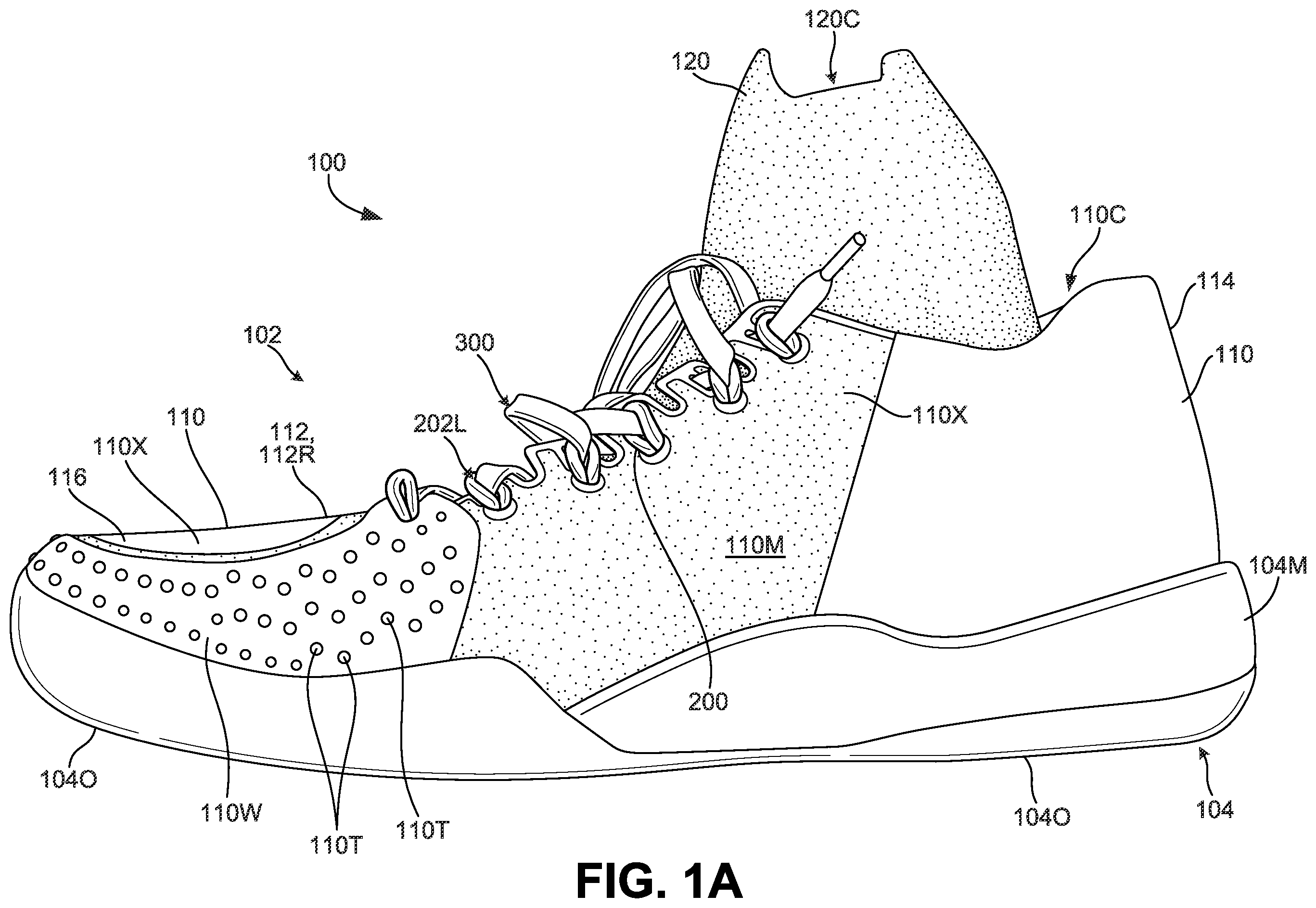
A- 1 D provide various views of an example article of footwear 100 in accordance with at least some aspects of this invention. A provides a medial side view of the article of footwear 100 , B provides a lateral side view, C provides a top view, and D provides a bottom view. This example article of footwear 100 includes an upper 102 and a sole structure 104 engaged with the upper 102 . While articles of footwear 100 in accordance with aspects of this invention may be designed for any desired type of end use, in this specifically illustrated example, the article of footwear 100 is designed for use in playing tennis.
The sole structure 104 of this illustrated example includes a midsole 104 M and an outsole 104 O, e.g., engaged with the midsole 104 M. The midsole 104 M absorbs energy and provides impact force attenuation and may be configured to support an entire plantar surface of a wearer's foot. The midsole 104 M may be made from any desired materials, including materials conventionally known and used in the footwear arts, such as polyurethane foams, ethylvinylacetate foams, and the like. Additionally or alternatively, the midsole 104 M may be made from one or more parts and may include other impact force attenuating structures, such as one or more of: one or more fluid-filled bladders, one or more mechanical shock absorbers, etc. The outsole 104 O provides traction and wear resistance and may be made from one or more parts. The outsole 104 O may be made from any desired materials, including materials conventionally known and used in the footwear arts, such as thermoplastic polyurethanes, rubbers, and the like. If desired, the outsole 104 O may be omitted at least at some locations at the bottom of the footwear 100 structure and/or the midsole 104 M may function as the outsole at least at some locations. Alternatively, if desired, the midsole 104 M may be omitted at least at some locations of the footwear 100 structure and/or the outsole 104 O may function as the midsole at least at some locations. The midsole 104 M and/or the outsole 104 O may include grooves, flex lines, or the like, e.g., to enhance flexibility and/or natural motion of the sole structure 104 , to provide traction, etc.
The components and structure of the upper 102 according to this specifically illustrated example of the invention now will be described in more detail with additional reference to A (a cross sectional view of an example footwear structure 100 ). The upper 102 of this example includes two main components (each of which may be made from one or more parts), namely an upper shell 110 and a bootie component 120 . The upper shell 110 of this example, which may be made from one or more parts, includes a plantar support surface 110 S, a lateral sidewall 110 L, and a medial sidewall 110 M. Each of the lateral sidewall 110 L and the medial sidewall 110 M extends upward from an outer perimeter 110 P of the plantar support surface 110 S. In this manner, the upper shell 110 defines an interior chamber 110 C into which the bootie component 120 is received.
The upper shell 110 of this example is made from multiple component parts. One main part is a textile and/or polymeric component 110 X forming much of the lateral sidewall 110 L, the medial sidewall 110 M, and the top panel 112 , e.g., over the instep and/or forefoot containing area of the upper 102 . A heel support 114 is provided around the heel area of the upper shell 110 , e.g., to provide additional support for the heel area of a wearer's foot. The heel support 114 may be made from a stiffer or less flexible material than the textile/polymeric component 110 X, e.g., from a rubber or thermoplastic polyurethane material. The heel support 114 may constitute a heel counter structure, if desired. The interior heel area of the upper shell 110 may include foam and/or gel type pads or comfort-enhancing components 114 P, e.g., that comfortably engage and/or conform in shape to the wearer's ankle (note also F ). The medial side of the forward toe and forefoot area of this example upper shell 110 includes a wear resistant component 110 W, which in this example may be made of a plastic material (e.g., a thermoplastic polyurethane, a rubber material, etc.). This wear resistant component 110 W is useful in this example footwear 100 structure to provide additional protection for the “big toe” area of the upper 102 , which can receive substantial wear when playing tennis (e.g., during serves, when changing direction, etc.). Additionally, if desired, the outer surface of the wear resistant component 110 W may include traction elements 110 T, e.g., made of rubber or other “gripping” material, to provide additional traction at appropriate times (e.g., during a serve, etc.). The traction elements 110 T are provided as small round “dots” of traction enhancing material in this illustrated example.
As mentioned above, in this example upper 102 structure, a bootie component 120 is received in the interior chamber 110 C defined (at least in part) by the upper shell 110 . In this example, the bootie component 120 has a “sock-like” configuration, e.g., made from a knit material, that closely receives, engages, and conforms in shape to the wearer's foot. Optionally, the bootie component 120 may be made by a circular knitting procedure and/or from a material that provides a relatively tight and optionally compression fit against the wearer's foot. The bootie component 120 may include one or more of: cottons; polyesters; Lycra, elastane, and/or other elastic materials; etc. The bootie component 120 of this example defines an interior chamber 120 C into which the wearer's foot is received.
E and 2 A illustrate example engagement of the bottom 120 B of the bootie component 120 with the plantar support surface 110 S of the upper shell 110 . E illustrates a bottom surface of the upper shell 110 and A is a cross sectional view of the article of footwear 100 . As shown in these figures, the bottom 120 B of the bootie component 120 is fixed to the plantar support surface 110 S of the upper shell 110 by a sewn seam 130 S that in this example extends completely around the plantar support surface 110 S as a complete loop (e.g., in an hourglass type shape). The sewn seam 130 S is located inward from the outer perimeter 110 P of the plantar support surface 110 S. Connections of this general type are described, for example, in co-pending U.S. patent application Ser. No. 14/927,751; U.S. Pat. Nos. 9,609,908; 9,210,866; and U.S. Pat. No. 8,578,632, each of which is entirely incorporated herein by reference, and the connections shown in these patent documents can be used in conjunction with footwear structures 100 in accordance with at least some examples of this invention. As shown in E , the sewn seam 130 S may be spaced inward from the outer perimeter edge 110 P of the plantar support surface 110 S by an inward spacing distance (e.g., distances D 4 to D 7 shown in E ). This inward spacing distance may vary over the path of the sewn seam 130 S, e.g., varying between 6 mm to 40 mm, and in some examples, between 6 mm and 25 mm. In at least some examples of this invention, the inward spacing distance (e.g., D 4 to D 7 ) may be at least 6 mm over at least 75% of an overall path of the seam 130 S. As some additional or alternative potential features, the inward spacing distance (e.g., D 4 to D 7 ) may be: (a) at least 12 mm over at least 75% of an overall path of the seam 130 S, (b) at least 6 mm over at least 80% of an overall path of the seam 130 S, (c) at least 12 mm over at least 80% of an overall path of the seam 130 S, (d) at least 6 mm over at least 90% of an overall path of the seam 130 S, (e) at least 12 mm over at least 90% of an overall path of the seam 130 S, (f) at least 6 mm over at least 95% of an overall path of the seam 130 S, and/or (g) at least 12 mm over at least 95% of an overall path of the seam 130 S.
While E shows the sewn seam 130 S extending completely around the plantar support surface 110 S to form an inwardly spaced closed loop, other options are possible without departing from this invention. For example, if desired, one or more breaks may be provided in the sewn seam (see F , thereby producing seam segments). In this manner, support and coupling between the bootie component 120 and the upper shell 110 can be provided where needed or desired and a more “decoupled” structure can be provided at other locations. Any desired number of seam 130 S segments and/or seam breaks around the plantar support surface 110 S can be provided without departing from the invention. The seam segments of F can have any of the inward spacing features (e.g., D 4 to D 7 ) described above. Additionally or alternatively, if desired, rather than or in addition to the sewn seam 130 S, the bottom of bootie component 120 may be fixed with the plantar support surface 110 S of the upper shell 110 by adhesives or cements and/or by mechanical connectors without departing from this invention.
The bootie component 120 may be fixed with the upper shell 110 in other manners and/or in other areas as well. In at least some examples of this invention, the bootie component 120 may be fixedly engaged with the upper shell 110 at fixed connections that include (and optionally consist essentially of):
•
• (a) one or more fixed bottom connections (e.g., shown by loop seam 130 S and/or seam segments 130 S in E and 1 F ) between the bootie component 120 and the plantar support surface 110 P of the upper shell 110 , wherein the one or more fixed bottom connections is/are spaced inward (distances D 4 -D 7 ), e.g., at least 6 mm, from the outer perimeter 110 P of the plantar support surface 110 S (the fixed bottom connection(s) may have any of the inward spacing features described above), and • (b) one or more fixed top connections (e.g., using one or more of adhesives, stitching, mechanical fasteners, etc.) between the bootie component 120 and a top forefoot area (e.g., within top panel 112 ) of the upper shell 110 , wherein each of the one or more fixed top connections is located within a fixed region 112 R (see C ) having: (i) a width dimension W (e.g., at a location of greatest width) of less than 5 cm in a medial side-to-lateral side direction (direction 22 , see E , which is perpendicular to heel-to-toe direction 20 in E ) of the upper 102 and/or the upper shell 110 and a length dimension L (e.g., at a location of greatest length) of less than 2 cm in a heel-to-toe direction (direction 20 from the rearmost heel location RH to a forwardmost toe location FT, see E ) of the upper 102 and/or the upper shell 110 and/or (ii) a fixed area of less than 10 cm 2 .
In at least some examples of this aspect of the invention, the top of the bootie component 120 will not be fixedly engaged with the top forefoot area of the upper shell 110 (e.g., not fixed to the inside surface of top panel 112 ) at a non-fixed region 116 located forward of the fixed region 112 R. Optionally, this non-fixed region 116 may have: (i) a second length dimension L 2 of at least 2 cm in the heel-to-toe direction of the upper 102 and/or upper shell 110 and/or (ii) a non-fixed area of at least 10 cm 2 . Additionally or alternatively, the bootie component 120 need not be fixedly engaged with a medial side 110 M of the upper shell 110 and/or the bootie component 120 need not be fixedly engaged with a lateral side 110 L of the upper shell 110 . The non-fixed region 116 may help allow the sock-like bootie component 120 conform to the wearer's foot and may help maintain a secure, “locked-down” feel of the upper 102 .
The fixed top connection(s) in these aspects or examples of the invention may have any one or more of the following properties: (a) a width dimension W (e.g., at a location of greatest width) of less than 4 cm in a medial side-to-lateral side direction, (b) a width dimension W (e.g., at a location of greatest width) of less than 3 cm in a medial side-to-lateral side direction, (c) a width dimension W (e.g., at a location of greatest width) of less than 2.5 cm in a medial side-to-lateral side direction, (d) a length dimension L (e.g., at a location of greatest length) of less than 1.75 cm in a heel-to-toe direction, (e) a length dimension L (e.g., at a location of greatest length) of less than 1.5 cm in a heel-to-toe direction, (f) a length dimension L (e.g., at a location of greatest length) of less than 1 cm in a heel-to-toe direction, (g) a fixed area of fixed region 112 R of less than 8 cm 2 , (h) a fixed area of fixed region 112 R of less than 6 cm 2 , and/or (i) a fixed area of fixed region 112 R of less than 5 cm 2 .
Additionally or alternatively, when present, the non-fixed region 116 forward of the fixed region 112 R in these aspects or examples of the invention may have any one or more of the following properties: (a) a width dimension W 2 (e.g., at a location of greatest width) of at least 3 cm in a medial side-to-lateral side direction, (b) a width dimension W 2 (e.g., at a location of greatest width) of at least 4 cm in a medial side-to-lateral side direction, (c) a width dimension W 2 (e.g., at a location of greatest width) of at least 5 cm in a medial side-to-lateral side direction, (d) a length dimension L 2 (e.g., at a location of greatest length) of at least 2.5 cm in a heel-to-toe direction, (e) a length dimension L 2 (e.g., at a location of greatest length) of at least 3.5 cm in a heel-to-toe direction, (f) a length dimension L 2 (e.g., at a location of greatest length) of at least 4 cm in a heel-to-toe direction, (g) a non-fixed area of non-fixed region 116 of at least 12 cm 2 , (h) a non-fixed area of non-fixed region 116 of at least 15 cm 2 , (i) a non-fixed area of non-fixed region 116 of at least 18 cm 2 , and/or (j) a non-fixed area of non-fixed region 116 of at least 21 cm 2 .
A- 2 C show further features that may be included in uppers 102 (or foot-covering components) and/or articles of footwear 100 (or other foot-receiving devices) in accordance with at least some examples of this invention. As shown in these figures, an interior midsole 140 is provided within the foot-receiving chamber 120 C of the bootie component 120 . The top surface 140 S of the interior midsole 140 may be contoured to correspond to the shape of a wearer's foot, and if desired, the outer edges 140 E may curve upward somewhat, e.g., to help stably position the wearer's foot on the top surface 140 S. The interior midsole 140 may be inserted into the foot-receiving chamber 120 C of the bootie component 120 , e.g., as shown in C , so that the interior midsole 140 will be in direct contact with and/or the closest footwear 100 component to a plantar surface of a wearer's foot. The interior midsole 140 may be made of a foam material, e.g., a lightweight foam material, made from polyurethane foam, ethylvinylacetate foam, and/or other foam materials. The interior midsole 140 may be thickest (e.g., the dimension from its top surface 140 S to its bottom surface 140 B) at a forward heel support area and/or a midfoot/arch support area of the midsole 140 (e.g., between lines 142 A and 142 B in B ).
The interior midsole 140 of this example footwear 100 structure may be somewhat thicker than conventional footwear insoles and/or sockliners. As some more specific examples, the interior midsole 140 may have: (a) a thickness of at least 6 mm through at least 50% of its top surface 140 S (measuring directly from the top surface 140 S to the bottom surface 140 B), (b) a thickness of at least 6 mm through at least 70% of its top surface 140 S, (c) a thickness of at least 6 mm through at least 80% of its top surface 140 S, (d) a thickness of at least 6 mm through at least 90% of its top surface 140 S, (e) a thickness of at least 9 mm through at least 50% of its top surface 140 S, (f) a thickness of at least 9 mm through at least 70% of its top surface 140 S, and/or (g) a thickness of at least 11 mm through at least 50% of its top surface 140 S. The foam material of the interior midsole 140 , its thickness, and its location directly beneath the wearer's foot enhance comfort of the overall footwear 100 structure of this specific example. In addition, the raised outer edges 140 E of the interior midsole 140 can help moderate the feel of the foot wrapping band(s) 200 , which will be described in more detail below. The location of this example interior midsole 140 (i.e., between the wearer's foot and the location where the foot wrapping bands 200 are connected to the upper shell 110 ) can help improve comfort and moderate wearer feel/awareness of the foot wrapping bands 200 , especially when a lace 300 pulls the foot wrapping bands 200 tight (as will be described in more detail below).
While the interior midsole 140 of this illustrated example is removable from the interior chamber 120 C of the bootie component 120 , other options are possible. For example, if desired, the interior midsole 140 could be fixed within the interior chamber 120 C, e.g., by adhesives, mechanical connectors (e.g., hook-and-loop fasteners), sewn seams, etc. Additionally or alternatively, if desired, a midsole component (e.g., foam, fluid-filled bladder(s), etc.) may be provided between the bootie component 120 and the upper shell 110 , e.g., in place of and/or in addition to an interior midsole 140 in the interior chamber 120 C of the bootie component 120 .
A- 4 G illustrate various potential features of foot wrapping bands 200 that may be included in articles of footwear 100 in accordance with at least some examples of this invention. As shown in these figures, each side (i.e., the lateral side and the medial side) of the article of footwear 100 includes at least one foot wrapping band 200 , and optionally a plurality of foot wrapping bands 200 on each side. Note also A- 1 C and 2 A . The wrapping band(s) 200 of these illustrated examples include a lace engaging element 202 L (e.g., in a generally central area of the band 200 ), (b) a rearwardly extending band segment 202 R extending from the lace engaging element 202 L (optionally extending between the upper shell 110 and the bootie component 120 ), and (c) a forwardly extending band segment 202 F extending from the lace engaging element 202 L (optionally between the upper shell 110 and the bootie component 120 ). Optionally, the rearwardly extending band segment 202 R may be engaged with the plantar support surface 110 S of the upper shell 110 at a fixed bottom connection spaced inward from the outer perimeter 110 P of the plantar support surface 110 S and/or the forwardly extending band segment 202 F extends forward of the rearwardly extending band segment 202 R and may be engaged with the plantar support surface 110 S at a fixed bottom connection spaced inward from the outer perimeter 110 P of the plantar support surface 110 S. If desired, the band segment(s) 202 R and/or 202 F may be engaged with the plantar support surface 110 S at location(s) spaced inward from the outer perimeter 110 P of the plantar support surface 110 S using the same fixed connection as used to engage the plantar support surface 110 S with the bootie component 120 (e.g., sewn seam 130 S, adhesives or cements, mechanical fasteners, etc.). As shown in A- 1 C , the lace engaging element 202 L extends through the openings in the upper components 110 M, 110 L and form a loop through which the lace 300 extends.
A- 3 D show additional potential features of foot wrapping bands 200 that may be included in articles of footwear 100 in accordance with at least some examples of this invention. As shown in these figures, the foot wrapping bands 200 change in cross sectional shape from a relatively thin and flat shape at the rearwardly extending segment 202 R and the forwardly extending segment 202 F to relatively circular shape at the lace engaging element 202 L. Transitional areas 202 T include an area intermediate in cross sectional shape between: (a) the relatively thin and flat cross sectional shape of rearwardly extending segment 202 R and forwardly extending segment 202 F and (b) the relatively circular cross sectional shape at the lace engaging element 202 L. One or more of the foot wrapping bands 200 may be formed as a unitary, one-piece construction, if desired. The relatively thin and flat shape of the forwardly extending segment 202 F and the rearwardly extending segment 202 R can help provide a more comfortable fit or feel, e.g., when a lace (e.g., 300 ) pulls the foot wrapping band(s) 200 tight, in some instances into contact with the wearer's foot. The thin and flat shape can help spread out the applied force and thus moderate the feel of the foot wrapping band(s) 200 against the wearer's foot.
As some more specific examples, at least one of the rearwardly extending band segments 202 R and/or the forwardly extending medial band segments 202 F has a longitudinal length L3, a width W3, and a thickness T3, wherein:
•
• T3≥1 mm, W3≥3T3, and L3≥10 W3.
In some examples, T3 will be greater than or equal to 2 mm and/or greater than or equal to 3 mm. As other options or alternatives, T3 may be less than 5 mm or even less than 4 mm and/or W 3 may be at least 3 mm, at least 5 mm, at least 8 mm, or even at least 10 mm. As other additional or alternative example features, in the lace engaging element 202 L area of the foot wrapping band(s) 200 , the lace engaging element 202 L may have a diameter D of less than 15 mm, and in some examples, a diameter of less than 12 mm, or even less than 10 mm. The transitional area(s) 202 T may have a length dimension of less than 25 mm, and in some examples, less than 20 mm, less than 15 mm, or even less than 10 mm.
In at least some examples of this aspect of the invention, the rearwardly extending segment 202 R and/or the forwardly extending segment 202 F may be shaped somewhat like a “flat” shoelace, and optionally made of the same material(s) as conventional shoelaces, e.g., for athletic footwear. As some more specific examples, the foot wrapping bands 200 (or at least the rearwardly extending segment 202 R and/or the forwardly extending segment 202 F thereof) may be made from leather, cotton, jute, hemp, other materials used in the manufacture of rope, synthetic fibers (e.g., polyesters), etc. In at least some examples of this invention, the foot wrapping bands 200 (or at least the rearwardly extending segment 202 R and/or the forwardly extending segment 202 F thereof) may be made from relatively “unstretchable” materials (e.g., materials that stretch less than 10% of their axial length under a tensile force of 50 lbs).
A- 4 G , along with A- 1 C and 2 A , illustrate one manner in which foot wrapping band(s) 200 may be engaged with a footwear upper 102 and/or a lace 300 in accordance with at least some examples of this invention. With particular reference to A , the upper shell 110 is illustrated with a set of foot wrapping bands 200 laid out on its interior surface. As shown in A , this example upper 102 (e.g., upper shell 110 ) includes a medial sidewall 110 M and a lateral sidewall 110 L, and a top panel 112 is engaged or integrally formed with at least one of the medial sidewall 110 M and/or the lateral sidewall 110 L. The medial sidewall 110 M, the lateral sidewall 110 L, and the top panel 112 define a lace engaging region 204 of the upper 102 and/or the upper shell 110 , and this lace engaging region 204 has a medial side edge 204 M, a lateral side edge 204 L, and a forward edge 204 F. This example upper 102 also may include a bottom plantar support surface 110 S component (not shown in A ) and/or a bootie component 120 , e.g., of the types described above and/or having any of the structural features, connections, and/or other characteristics described above. The outer edge of the upper shell 110 shown in A may be engaged with a separate bottom plantar support surface 110 S component (such as a footwear strobel member), e.g., as shown in A .
As further shown in A , the medial side edge 204 M of the lace engaging region 204 of this illustrated example upper shell 110 includes one or more of a first medial side opening 210 O, a second medial side opening 212 O located forward of the first medial side opening 210 O, a third medial side opening 214 O located forward of the second medial side opening 212 O, a fourth medial side opening 216 O located forward of the third medial side opening 214 O, a fifth medial side opening 218 O located forward of the fourth medial side opening 216 O, and a rearmost medial side opening 220 O located rearward of the first medial side opening 210 O. Similarly, the lateral side edge 204 L of the lace engaging region 204 of this illustrated example upper shell 110 includes one or more of a first lateral side opening 230 O, a second lateral side opening 232 O located forward of the first lateral side opening 230 O, a third lateral side opening 234 O located forward of the second lateral side opening 232 O, a fourth lateral side opening 236 O located forward of the third lateral side opening 234 O, a fifth lateral side opening 238 O located forward of the fourth lateral side opening 236 O, and a rearmost lateral side opening 240 O located rearward of the first lateral side opening 230 O. Note also D and 4 E . The upper shell 110 of this illustrated example further includes lace engaging slits or slots 222 located adjacent the side openings 210 O- 220 O and 230 O- 240 O. In this illustrated example, each side opening 210 O- 220 O and 230 O- 240 O has a lace engaging slit or slot 222 associated with it, but the side opening 210 O- 220 O and 230 O- 240 O is not continuous with its associated lace engaging slit or slot 222 . In other words, in this illustrated example, a continuous portion 110 V of the upper shell 110 extends between each side opening 210 O- 220 O and 230 O- 240 O and its associated lace engaging slit or slot 222 .
The layout of foot wrapping bands of this example now will be described in more detail. Note, for example, A and 4 A . A first medial side foot wrapping band 250 includes: (a) a first medial lace engaging element (not shown in the view of A but akin to element 202 L) extending through the first medial side opening 210 O, (b) a first medial band segment 250 R extending from the first medial lace engaging element and between the medial sidewall 110 M and the bootie component 120 , wherein the first medial band segment 250 R is engaged with the bottom plantar support surface 110 S of the upper shell 110 at a fixed bottom connection (e.g., sewn seam 130 S) that is spaced inward from the outer perimeter edge 110 P of the bottom plantar support surface 110 S, and (c) a second medial band segment 250 F extending from the first medial lace engaging element and between the medial sidewall 110 M and the bootie component 120 , wherein the second medial band segment 250 F extends forward of the first medial band segment 250 R and is engaged with the bottom plantar support surface 110 S of the upper shell 110 at a fixed bottom connection (e.g., sewn seam 130 S) that is spaced inward from the outer perimeter edge 110 P of the plantar support surface 110 S. In this manner, first medial band segment 250 R and second medial band segment 250 F form a “V” shaped structure that wraps around a medial side of the wearer's foot and may tighten against the foot when a lace 300 is tightened. The vertex of this “V” shaped structure forms the lace engaging element.
This example upper 102 structure further includes a second medial side foot wrapping band 252 that includes: (a) a second medial lace engaging element (not shown in the view of A but akin to element 202 L) extending through the second medial side opening 212 O, (b) a third medial band segment 252 R extending from the second medial lace engaging element and between the medial sidewall 110 M and the bootie component 120 , wherein the third medial band segment 252 R is engaged with the bottom plantar support surface 110 S of the upper shell 110 at a fixed bottom connection (e.g., sewn seam 130 S) that is spaced inward from the outer perimeter edge 110 P of the bottom plantar support surface 110 S, and (c) a fourth medial band segment 252 F extending from the second medial lace engaging element and between the medial sidewall 110 M and the bootie component 120 , wherein the fourth medial band segment 252 F extends forward of the third medial band segment 252 R and is engaged with the bottom plantar support surface 110 S of the upper shell 110 at a fixed bottom connection (e.g., sewn seam 130 S) spaced inward from the outer perimeter edge 110 P of the bottom plantar support surface 110 S. In this manner, third medial band segment 252 R and fourth medial band segment 252 F form a “V” shaped structure (with the lace engaging element at the “V′ s” vertex) that wraps around a medial side of the wearer's foot and may tighten against the foot when a lace 300 is tightened. If desired, as shown in A , the medial side foot wrapping bands 250 and 252 may be arranged such that the third medial band segment 252 R crosses the second medial band segment 250 F along the medial sidewall 110 M of the upper shell 110 (and along the medial side of a wearer's foot).
A third medial side foot wrapping band 254 is provided in this illustrated example structure that includes: (a) a third medial lace engaging element (not shown in the view of A but akin to element 202 L) extending through the third medial side opening 214 O, (b) a fifth medial band segment 254 R extending from the third medial lace engaging element and between the medial sidewall 110 M and the bootie component 120 , wherein the fifth medial band segment 254 R is engaged with the bottom plantar support surface 110 S of the upper shell 110 at a fixed bottom connection (e.g., sewn seam 130 S) that is spaced inward from the outer perimeter edge 110 P of the bottom plantar support surface 110 S, and (c) a sixth medial band segment 254 F extending from the third medial lace engaging element and between the medial sidewall 110 M and the bootie component 120 , wherein the sixth medial band segment 254 F extends forward of the fifth medial band segment 254 R and is engaged with the bottom plantar support surface 110 S of the upper shell 110 at a fixed bottom connection (e.g., sewn seam 130 S) spaced inward from the outer perimeter edge 110 P of the bottom plantar support surface 110 S. In this manner, fifth medial band segment 254 R and sixth medial band segment 254 F form a “V” shaped structure (with the lace engaging element at the “V′ s” vertex) that wraps around a medial side of the wearer's foot and may tighten against the foot when a lace 300 is tightened. If desired, as shown in A , the medial side foot wrapping bands 252 and 254 may be arranged such that the fifth medial band segment 254 R crosses the fourth medial band segment 252 F along the medial sidewall 110 M of the upper shell 110 (and along the medial side of a wearer's foot).
A fourth medial side foot wrapping band 256 provided in this illustrated example upper 102 structure includes: (a) a fourth medial lace engaging element (not shown in the view of A but akin to element 202 L) extending through the fourth medial side opening 216 O, (b) a seventh medial band segment 256 R extending from the fourth medial lace engaging element and between the medial sidewall 110 M and the bootie component 120 , wherein the seventh medial band segment 256 R is engaged with the bottom plantar support surface 110 S of the upper shell 110 at a fixed bottom connection (e.g., sewn seam 130 S) that is spaced inward from the outer perimeter edge 110 P of the bottom plantar support surface 110 S, and (c) an eighth medial band segment 256 F extending from the fourth medial lace engaging element and between the medial sidewall 110 M and the bootie component 120 , wherein the eighth medial band segment 256 F extends forward of the seventh medial band segment 256 R and is engaged with the bottom plantar support surface 110 S of the upper shell 110 at a fixed bottom connection (e.g., sewn seam 130 S) spaced inward from the outer perimeter edge 110 P of the bottom plantar support surface 110 S. In this manner, seventh medial band segment 256 R and eighth medial band segment 256 F form a “V” shaped structure (with the lace engaging element at the “V′ s” vertex) that wraps around a medial side of the wearer's foot and may tighten against the foot when a lace 300 is tightened. If desired, as shown in A , the medial side foot wrapping bands 254 and 256 may be arranged such that the seventh medial band segment 256 R crosses the sixth medial band segment 254 F along the medial sidewall 110 M of the upper shell 110 (and along the medial side of a wearer's foot).
This example upper 102 structure further includes a fifth medial side foot wrapping band 258 having: (a) a fifth medial lace engaging element (not shown in the view of A but akin to element 202 L) extending through the fifth medial side opening 218 O, (b) a ninth medial band segment 258 R extending from the fifth medial lace engaging element and between the medial sidewall 110 M and the bootie component 120 , wherein the ninth medial band segment 258 R is engaged with the bottom plantar support surface 110 S of the upper shell 110 at a fixed bottom connection (e.g., sewn seam 130 S) that is spaced inward from the outer perimeter edge 110 P of the bottom plantar support surface 110 S, and (c) a tenth medial band segment 258 F extending from the fifth medial lace engaging element and between the medial sidewall 110 M and the bootie component 120 , wherein the tenth medial band segment 258 F extends forward of the ninth medial band segment 258 R and is engaged with the bottom plantar support surface 110 S of the upper shell 110 at a fixed bottom connection (e.g., sewn seam 130 S) spaced inward from the outer perimeter edge 110 P of the bottom plantar support surface 110 S. In this manner, ninth medial band segment 258 R and tenth medial band segment 258 F form a “V” shaped structure (with the lace engaging element at the “V′s” vertex) that wraps around a medial side of the wearer's foot and may tighten against the foot when a lace 300 is tightened. If desired, as shown in A , the medial side foot wrapping bands 256 and 258 may be arranged such that the ninth medial band segment 258 R crosses the eighth medial band segment 256 F along the medial sidewall 110 M of the upper shell 110 (and along the medial side of a wearer's foot).
The medial side of the upper 102 of this specifically illustrated example further includes a rearmost medial side foot wrapping band 260 that includes: (a) a medial lace engaging element (not shown in the view of A but akin to element 202 L) extending through the rearmost medial side opening 220 O; (b) a rearward extending medial band segment 260 R extending from the medial lace engaging element and between the medial sidewall 110 M and the bootie component 120 , wherein the rearward extending medial band segment 260 R is engaged with (i) a rear heel area of the bootie component 120 (see also F ) and/or (ii) the bottom plantar support surface 110 S of the upper shell 110 at a fixed bottom connection (e.g., sewn seam 130 S) that is spaced inward from the outer perimeter edge 110 P of the bottom plantar support surface 110 S; and (c) another medial band segment 260 F extending from the medial lace engaging element and between the medial sidewall 110 M and the bootie component 120 , wherein this other medial band segment 260 F extends forward of the rearward extending medial band segment 260 R and is engaged with the bottom plantar support surface 110 S of the upper shell 110 at a fixed bottom connection (e.g., sewn seam 130 S) spaced inward from the outer perimeter edge 110 P of the bottom plantar support surface 110 S and may tighten against the foot when a lace 300 is tightened. In this manner, the medial band segments 260 R and 260 F form a “V” shaped structure (with the lace engaging element at the “V′ s” vertex) that wraps around a medial side of the wearer's foot. If desired, as shown in A , the first medial side foot wrapping band 250 and the rearmost foot wrapping band 260 may be arranged such that the first medial band segment 250 R crosses the medial band segment 260 F along the medial sidewall 110 M of the upper shell 110 (and along the medial side of a wearer's foot).
The layout of the foot wrapping bands on the lateral side of this example upper 102 now will be described in more detail. A first lateral side foot wrapping band 270 includes:
(a) a first lateral lace engaging element (not shown in the view of A but akin to element 202 L) extending through the first lateral side opening 230 O, (b) a first lateral band segment 270 R extending from the first lateral lace engaging element and between the lateral sidewall 110 L and the bootie component 120 , wherein the first lateral band segment 270 R is engaged with the bottom plantar support surface 110 S of the upper shell 110 at a fixed bottom connection (e.g., sewn seam 130 S) that is spaced inward from the outer perimeter edge 110 P of the bottom plantar support surface 110 S, and (c) a second lateral band segment 270 F extending from the first lateral lace engaging element and between the lateral sidewall 110 L and the bootie component 120 , wherein the second lateral band segment 270 F extends forward of the first lateral band segment 270 R and is engaged with the bottom plantar support surface 110 S of the upper shell 110 at a fixed bottom connection (e.g., sewn seam 130 S) that is spaced inward from the outer perimeter edge 110 P of the plantar support surface 110 S. In this manner, first lateral band segment 270 R and second lateral band segment 270 F form a “V” shaped structure that wraps around a lateral side of the wearer's foot and may tighten against the foot when a lace 300 is tightened. The lace engaging element is provided at the vertex of this “V” shaped structure.
This example upper 102 structure further includes a second lateral side foot wrapping band 272 that includes: (a) a second lateral lace engaging element (not shown in the view of A but akin to element 202 L) extending through the second lateral side opening 232 O, (b) a third lateral band segment 272 R extending from the second lateral lace engaging element and between the lateral sidewall 110 L and the bootie component 120 , wherein the third lateral band segment 272 R is engaged with the bottom plantar support surface 110 S of the upper shell 110 at a fixed bottom connection (e.g., sewn seam 130 S) that is spaced inward from the outer perimeter edge 110 P of the bottom plantar support surface 110 S, and (c) a fourth lateral band segment 272 F extending from the second lateral lace engaging element and between the lateral sidewall 110 L and the bootie component 120 , wherein the fourth lateral band segment 272 F extends forward of the third lateral band segment 272 R and is engaged with the bottom plantar support surface 110 S of the upper shell 110 at a fixed bottom connection (e.g., sewn seam 130 S) spaced inward from the outer perimeter edge 110 P of the bottom plantar support surface 110 S. In this manner, third lateral band segment 272 R and fourth lateral band segment 272 F form a “V” shaped structure (with the lace engaging element at the “V′s” vertex) that wraps around a lateral side of the wearer's foot and may tighten against the foot when a lace 300 is tightened. If desired, as shown in A , the lateral side foot wrapping bands 270 and 272 may be arranged such that the third lateral band segment 272 R crosses the second lateral band segment 270 F along the lateral sidewall 110 L of the upper shell 110 (and along the lateral side of a wearer's foot).
A third lateral side foot wrapping band 274 is provided in this illustrated example structure that includes: (a) a third lateral lace engaging element (not shown in the view of A but akin to element 202 L) extending through the third lateral side opening 234 O, (b) a fifth lateral band segment 274 R extending from the third lateral lace engaging element and between the lateral sidewall 110 L and the bootie component 120 , wherein the fifth lateral band segment 274 R is engaged with the bottom plantar support surface 110 S of the upper shell 110 at a fixed bottom connection (e.g., sewn seam 130 S) that is spaced inward from the outer perimeter edge 110 P of the bottom plantar support surface 110 S, and (c) a sixth lateral band segment 274 F extending from the third lateral lace engaging element and between the lateral sidewall 110 L and the bootie component 120 , wherein the sixth lateral band segment 274 F extends forward of the fifth lateral band segment 274 R and is engaged with the bottom plantar support surface 110 S of the upper shell 110 at a fixed bottom connection (e.g., sewn seam 130 S) spaced inward from the outer perimeter edge 110 P of the bottom plantar support surface 110 S. In this manner, fifth lateral band segment 274 R and sixth lateral band segment 274 F form a “V” shaped structure (with the lace engaging element at the “V′ s” vertex) that wraps around a lateral side of the wearer's foot and may tighten against the foot when a lace 300 is tightened. If desired, as shown in A , the lateral side foot wrapping bands 272 and 274 may be arranged such that the fifth lateral band segment 274 R crosses the fourth lateral band segment 272 F along the lateral sidewall 110 L of the upper shell 110 (and along the lateral side of a wearer's foot).
A fourth lateral side foot wrapping band 276 provided in this illustrated example upper 102 structure includes: (a) a fourth lateral lace engaging element (not shown in the view of A but akin to element 202 L) extending through the fourth lateral side opening 236 O, (b) a seventh lateral band segment 276 R extending from the fourth lateral lace engaging element and between the lateral sidewall 110 L and the bootie component 120 , wherein the seventh lateral band segment 276 R is engaged with the bottom plantar support surface 110 S of the upper shell 110 at a fixed bottom connection (e.g., sewn seam 130 S) that is spaced inward from the outer perimeter edge 110 P of the bottom plantar support surface 110 S, and (c) an eighth lateral band segment 276 F extending from the fourth lateral lace engaging element and between the lateral sidewall 110 L and the bootie component 120 , wherein the eighth lateral band segment 276 F extends forward of the seventh lateral band segment 276 R and is engaged with the bottom plantar support surface 110 S of the upper shell 110 at a fixed bottom connection (e.g., sewn seam 130 S) spaced inward from the outer perimeter edge 110 P of the bottom plantar support surface 110 S. In this manner, seventh lateral band segment 276 R and eighth lateral band segment 276 F form a “V” shaped structure (with the lace engaging element at the “V′s” vertex) that wraps around a lateral side of the wearer's foot and may tighten against the foot when a lace 300 is tightened. If desired, as shown in A , the lateral side foot wrapping bands 274 and 276 may be arranged such that the seventh lateral band segment 276 R crosses the sixth lateral band segment 274 F along the lateral sidewall 110 L of the upper shell 110 (and along the lateral side of a wearer's foot).
This example upper 102 structure further includes a fifth lateral side foot wrapping band 278 having: (a) a fifth lateral lace engaging element (not shown in the view of A but akin to element 202 L) extending through the fifth lateral side opening 238 O, (b) a ninth lateral band segment 278 R extending from the fifth lateral lace engaging element and between the lateral sidewall 110 L and the bootie component 120 , wherein the ninth lateral band segment 278 R is engaged with the bottom plantar support surface 110 S of the upper shell 110 at a fixed bottom connection (e.g., sewn seam 130 S) that is spaced inward from the outer perimeter edge 110 P of the bottom plantar support surface 110 S, and (c) a tenth lateral band segment 278 F extending from the fifth lateral lace engaging element and between the lateral sidewall 110 L and the bootie component 120 , wherein the tenth lateral band segment 278 F extends forward of the ninth lateral band segment 278 R and is engaged with the bottom plantar support surface 110 S of the upper shell 110 at a fixed bottom connection (e.g., sewn seam 130 S) spaced inward from the outer perimeter edge 110 P of the bottom plantar support surface 110 S. In this manner, ninth lateral band segment 278 R and tenth lateral band segment 278 F form a “V” shaped structure (with the lace engaging element at the “V′ s” vertex) that wraps around a lateral side of the wearer's foot and may tighten against the foot when a lace 300 is tightened. If desired, as shown in A , the lateral side foot wrapping bands 276 and 278 may be arranged such that the ninth lateral band segment 278 R crosses the eighth lateral band segment 276 F along the lateral sidewall 110 L of the upper shell 110 (and along the lateral side of a wearer's foot).
The lateral side of the upper 102 of this specifically illustrated example further includes a rearmost lateral side foot wrapping band 280 that includes: (a) a lateral lace engaging element (not shown in the view of A but akin to element 202 L) extending through the rearmost lateral side opening 240 O; (b) a rearward extending lateral band segment 280 R extending from the lateral lace engaging element and between the lateral sidewall 110 L and the bootie component 120 , wherein the rearward extending lateral band segment 280 R is engaged with (i) a rear heel area of the bootie component 120 (see also F ) and/or (ii) the bottom plantar support surface 110 S of the upper shell 110 at a fixed bottom connection (e.g., sewn seam 130 S) that is spaced inward from the outer perimeter edge 110 P of the bottom plantar support surface 110 S; and (c) another lateral band segment 280 F extending from the lateral lace engaging element and between the lateral sidewall 110 L and the bootie component 120 , wherein this other lateral band segment 280 F extends forward of the rearward extending lateral band segment 280 R and is engaged with the bottom plantar support surface 110 S of the upper shell 110 at a fixed bottom connection (e.g., sewn seam 130 S) spaced inward from the outer perimeter edge 110 P of the bottom plantar support surface 110 S. In this manner, the lateral band segments 280 R and 280 F form a “V” shaped structure (with the lace engaging element at the “V′ s” vertex) that wraps around a lateral side of the wearer's foot and may tighten against the foot when a lace 300 is tightened. If desired, as shown in A , the first lateral side foot wrapping band 270 and the rearmost foot wrapping band 280 may be arranged such that the first lateral band segment 270 R crosses the lateral band segment 280 F along the lateral sidewall 110 L of the upper shell 110 (and along the lateral side of a wearer's foot).
As further shown in A- 1 C, 4 B, 4 C, 4 E, and 4 F , the lace engaging elements 202 L of the various foot wrapping bands (e.g., 200 , 250 , 252 , 254 , 256 , 258 , 260 , 270 , 272 , 274 , 276 , 278 , and 280 ) engage a shoelace 300 . Pulling on the shoelace 300 tightens the foot wrapping bands (e.g., one or more of 200 , 250 , 252 , 254 , 256 , 258 , 260 , 270 , 272 , 274 , 276 , 278 , and 280 ) around the wearer's foot. Tightening the lace 300 , together with the various features described above (e.g.: (a) the “V” shapes formed by the foot wrapping band segments, (b) the “overlapping” or “intersecting” nature of the foot wrapping band segments along the side of the wearer's foot, (c) the fixing location for the foot wrapping band segments and/or the bootie component 120 with the upper shell 110 inward from the outer perimeter edge 110 P of the plantar support surface 110 S (and beneath/beyond the bight line where the upper shell 110 meets the bootie component 120 ), and/or (d) the form fitting sock-like bootie component 120 ), work together to provide a secure and “locked down” feel of the upper 102 on the wearer's foot.
As noted above, in at least some examples of this invention, the upper shell 110 may include lace engaging slits or slots 222 located adjacent the side openings 210 O- 220 O and 230 O- 240 O through which the lace engaging element 202 L of the foot wrapping bands bands (e.g., 200 , 250 , 252 , 254 , 256 , 258 , 260 , 270 , 272 , 274 , 276 , 278 , and 280 ) extend. B- 4 E provide close up views of at least some of the side openings 210 O- 220 O and 230 O- 240 O through which the lace engaging element 202 L of the foot wrapping bands (e.g., 200 , 250 , 252 , 254 , 256 , 258 , 260 , 270 , 272 , 274 , 276 , 278 , and 280 ) extend and the lace engaging slit or slot 222 through which the lace 300 extends. As shown, in these illustrated examples, the side opening(s) 210 O- 220 O and 230 O- 240 O are not continuous with its associated lace engaging slit or slot 222 . In other words, in this illustrated example, a continuous portion 110 V of the upper shell 110 extends between each side opening 210 O- 220 O and 230 O- 240 O and its associated lace engaging slit or slot 222 . In this example upper 102 , lace 300 passes through both slits/slots 222 of the upper shell 110 and the lace engaging elements 202 L of the foot wrapping bands 250 , 252 , 254 , 256 , 258 , 260 , 270 , 272 , 274 , 276 , 278 , and 280 . The slits/slots 222 are located closer to their respective lateral edge 204 L and medial edge 204 M of the lace engaging region 204 of the upper shell 110 than are the respective side openings 210 O- 220 O and 230 O- 240 O (e.g., the openings 210 O- 220 O and 230 O- 240 O are located closer to a bottom edge of the upper shell 110 than are their respective slits/slots 222 ).
If desired, as best shown perhaps in D , the edges of the side opening(s) 210 O- 220 O and/or 230 O- 240 O and/or lace engaging slits or slots 222 formed in the upper shell 110 may include a reinforcing structure 110 R, e.g., to prevent undesired tearing of the upper 102 and/or upper shell 110 material when the lace 300 is tightened or the upper 102 is otherwise stressed. This reinforcement 110 R may constitute a coating or other wear resistant and/or tear resistant material, e.g., applied around the opening(s) and/or slit(s), such as a TPU or other tear resistant polymeric material. In use, the lace 300 extends through the slits/slots 222 and through the lace engaging element 202 L extending through the side openings 210 O- 220 O and 230 O- 240 O and may be used to tighten the footwear 100 to the wearer's foot while reinforcements 110 R prevent tearing of the upper shell 110 , e.g., when the lace 300 is tightened.
B- 4 D further illustrate that the lace engaging slits or slots 222 in this illustrated example are generally oriented transverse to its respective lace engaging edge of the upper shell 110 (e.g., transverse to the medial side edge 204 M or the lateral side edge 204 L of the lace engaging region 204 ) and/or generally parallel to the forward edge 204 F of the lace engaging region 204 . Also, as shown in these figures, the slits/slots 222 generally extend in a side-to-side and/or top-to-bottom direction of the upper 102 (and not in a heel-to-toe direction). In this manner, the lace 300 can move upward and/or downward and/or sideways in the slit or slot 222 as the lace 300 is tightened. These features can help assure that the lace 300 better engages and pulls the lace engaging elements 202 L of the foot wrapping bands (e.g., 200 , 250 , 252 , 254 , 256 , 258 , 260 , 270 , 272 , 274 , 276 , 278 , and/or 280 ), thereby better tightening the foot wrapping bands around the wearer's foot (providing better support, a better “locked down” feel, etc.).
G shows another example upper shell 410 with foot wrapping bands ( 250 , 252 , 254 , 256 , 258 , 260 , 270 , 272 , 274 , 276 , 278 , and/or 280 ) associated with it similar to the structure shown in A . When the same reference numbers are used in G as used in the other figures described above, the same or a similar part is intended, and a more detailed description of the same or similar parts may be omitted. In the upper shell 410 of G , however, the side openings 210 O- 220 O and 230 O- 240 O are omitted as compared to the upper shell 110 shown in A . Rather, the lace engaging element(s) 202 L of the foot wrapping band(s) 250 , 252 , 254 , 256 , 258 , 260 , 270 , 272 , 274 , 276 , 278 , and/or 280 extend through the slits/slots 222 , and the lace 300 can directly engage the lace engaging element(s) 202 L of the foot wrapping band(s) 250 , 252 , 254 , 256 , 258 , 260 , 270 , 272 , 274 , 276 , 278 , and/or 280 without directly extending through the slits/slots 222 (i.e., in this upper shell 410 , the lace 300 does not extend through slits/slots 222 ). The foot wrapping band(s) 250 , 252 , 254 , 256 , 258 , 260 , 270 , 272 , 274 , 276 , 278 , and/or 280 can move upward and/or downward and/or sideways in the slit/slot 222 as the lace 300 is tightened. These features can help assure that the lace 300 better engages and pulls the lace engaging elements 202 L of the foot wrapping bands (e.g., 200 , 250 , 252 , 254 , 256 , 258 , 260 , 270 , 272 , 274 , 276 , 278 , and/or 280 ), thereby better tightening the foot wrapping bands around the wearer's foot (providing better support, a better “locked down” feel, etc.).
III. Conclusion
The present invention is disclosed above and in the accompanying drawings with reference to a variety of embodiments. The purpose served by the disclosure, however, is to provide an example of the various features and concepts related to the invention, not to limit the scope of the invention. One skilled in the relevant art will recognize that numerous variations and modifications may be made to the embodiments described above without departing from the scope of the present invention, as defined by the appended claims.
Figures (15)
Citations
This patent cites (111)
- US1463278
- US1603144
- US1976819
- US2345057
- US2539761
- US2798309
- US3091871
- US3191321
- US3323232
- US4592154
- US4811500
- US4860464
- US4899466
- US4916833
- US4955147
- US5214863
- US5259126
- US5319869
- US5454172
- US5499459
- US5678329
- US5692319
- US5775006
- US5784808
- US5907912
- US5992057
- US6453579
- US6467193
- US6925734
- USD517297
- US7047668
- US7073279
- US7086181
- US7434336
- US8061059
- US8161666
- US8479415
- US8578632
- US8869435
- US8973410
- US9107474
- US9192204
- US9210966
- US9414638
- US9565898
- US9609908
- US9763495
- US9770065
- US9839259
- US10051918
- US10362832
- US10405606
- US10945491
- US11083248
- US11122853
- US11206898
- US11672305
- US2002/0148142
- US2006/0101669
- US2006/0123663
- US2007/0000150
- US2007/0011910
- US2007/0062067
- US2007/0227037
- US2009/0100713
- US2010/0071230
- US2011/0016749
- US2011/0197475
- US2012/0011744
- US2012/0030965
- US2012/0246973
- US2012/0304493
- US2013/0104422
- US2014/0090274
- US2014/0202042
- US2015/0121724
- US2015/0150339
- US2015/0257475
- US2015/0257476
- US2016/0058100
- US2016/0066647
- US2016/0088901
- US2016/0302513
- US2016/0331083
- US2017/0027272
- US2017/0127760
- US2017/0181501
- US2017/0231324
- US2017/0265560
- US2017/0273404
- US2018/0343966
- US2018/0360167
- US2019/0082792
- US2019/0246742
- US2019/0246743
- US2019/0274392
- US2019/0307209
- US2019/0350314
- US2020/0046076
- US2022/0132995
- US2023/0255318
- US101267752
- US101909471
- US105495845
- US106136453
- US0570621
- US1332097
- US2501977
- US465012
- US2465973
- US101902109