Abstract
A driving mechanism is provided, including a fixed part, a movable part connected to the fixed part, a first connecting member, and a first wire. The first connecting member is hinged to the fixed part and connected to the movable part. The first wire has SMA material and is connected between the fixed part and the first connecting member. When the first wire contracts in length, the first connecting member rotates relative to the fixed part, and the movable part is driven to move relative to the fixed part.
Claims (19)
1. A driving mechanism for moving an optical element, comprising: a fixed part; a movable part, connected to the fixed part, wherein the optical element is disposed on the movable part; a first connecting member, having a free end and a connection end connected to the movable part; a hinge, pivotally connecting the first connecting member to the fixed part; and a first wire, comprising Shape Memory Alloy (SMA) material and connecting the free end to the fixed part; wherein in a case that the first wire contracts in length, the first connecting member is forced to rotate relative to the fixed part around the hinge, and the movable part is forced to move relative to the fixed part in a first direction; wherein the fixed part has a bottom plate, the first connecting member and the hinge comprise metal, and the first wire is electrically connected to a circuit structure on the bottom plate via the first connecting member and the hinge.
19. A driving mechanism for moving an optical element, comprising: a fixed part; a movable part, connected to the fixed part, wherein the optical element is disposed on the movable part; a circuit unit, disposed on the fixed part, wherein the circuit unit has an outer frame, an inner frame, and a plurality of rods connected between the outer and inner frames; a first connecting member, having a free end and a connection end connected to the movable part; a hinge, pivotally connecting the first connecting member to the fixed part; and a first wire, comprising Shape Memory Alloy (SMA) material and connecting the free end to the fixed part; wherein in a case that the first wire contracts in length, the first connecting member is forced to rotate relative to the fixed part around the hinge, and the movable part is forced to move relative to the fixed part in a first direction; wherein the outer frame is connected to the fixed part, and the inner frame contacts a conductive terminal on the movable part for electrically connecting to the first wire.
Show 17 dependent claims
2. The driving mechanism as claimed in claim 1 , wherein the distance between the first wire and the hinge is shorter than the distance between the connection end and the hinge.
3. The driving mechanism as claimed in claim 1 , further comprising a shaft extending through the movable part and connecting to the fixed part, wherein in a case that the first wire contracts in length, the first connecting member rotates relative to the fixed part and forces the movable part to slide along the shaft.
4. The driving mechanism as claimed in claim 3 , wherein the shaft is parallel to an optical axis of the optical element.
5. The driving mechanism as claimed in claim 4 , wherein the first wire is located between the hinge and the connection end along a first axis that is perpendicular to the optical axis.
6. The driving mechanism as claimed in claim 5 , wherein the first wire is located between the hinge and the shaft along the first axis.
7. The driving mechanism as claimed in claim 1 , wherein the first connecting member further has a pivot portion for receiving the hinge, a resistance arm connected between the pivot portion and the connection end, and an effort arm connected between the pivot portion and the free end, wherein the resistance arm is longer than the effort arm.
8. The driving mechanism as claimed in claim 7 , wherein the resistance arm has a C-shaped or U-shaped structure.
9. The driving mechanism as claimed in claim 7 , wherein the resistance arm forms a hole, and an optical axis of the optical element extends through the hole.
10. The driving mechanism as claimed in claim 1 , further comprising a second connecting member and a second wire, wherein the second connecting member is hinged on the fixed part, and the second wire comprises Shape Memory Alloy (SMA) material and connects the second connecting member to the fixed part, wherein in a case that the second wire contracts in length, the second connecting member is forced to rotate relative to the fixed part, and the movable part is forced to move relative to the fixed part in a second direction opposite to the first direction.
11. The driving mechanism as claimed in claim 10 , wherein when viewed along a second axis that is perpendicular to an optical axis of the optical element, the first and second connecting members partially overlap.
12. The driving mechanism as claimed in claim 10 , wherein the movable part includes a first slider and a second slider, and the driving mechanism further comprises a third wire connecting to the first and second sliders, wherein in a case that the third wire contracts in length, the first slider is forced to move relative to the second slider.
13. The driving mechanism as claimed in claim 12 , wherein the driving mechanism further comprises two third wires connected between the first and second sliders for driving the first slider to move relative to the second slider either in the first direction or in the second direction.
14. The driving mechanism as claimed in claim 1 , wherein the driving mechanism further comprises a circuit unit disposed on the fixed part, and the circuit unit has a base portion, a side portion, and a bent portion, wherein the base portion is connected to the fixed part, the side portion connects the base portion to the bent portion, and the side portion and the bent portion are perpendicular to the base portion.
15. The driving mechanism as claimed in claim 14 , wherein the bent portion has an L-shaped structure connected between the side portion and the movable part.
16. The driving mechanism as claimed in claim 14 , wherein the driving mechanism further comprises a magnet disposed on the movable part and a Hall effect sensor disposed on the base portion of the circuit unit for sensing the magnet.
17. The driving mechanism as claimed in claim 14 , wherein the bent portion contacts a conductive terminal on the movable part for electrically connecting to the first wire.
18. The driving mechanism as claimed in claim 14 , wherein an opening is formed between the base portion and the side portion, and the hinge extends through the opening.
Full Description
Show full text →
CROSS REFERENCE TO RELATED APPLICATIONS
This application claims priority of provisional U.S. Patent Application Ser. No. 63/209,750, filed on Jun. 11, 2021, the entirety of which is incorporated by reference herein.
BACKGROUND OF THE INVENTION
Field of the Invention
The application relates in general to a driving mechanism, and in particular, to a driving mechanism for moving an optical element.
Description of the Related Art
As technology has advanced, a lot of electronic devices (for example, laptop computers and smartphones) have incorporated the functionality of taking photographs and recording video. These electronic devices have become more commonplace, and have been developed to be more convenient and thin. More and more options are provided for users to choose from.
In some electronic devices, several coils and magnets are usually used for adjusting the focus of a lens. However, miniaturization of the electronic devices may increase the difficulty of mechanical design, and it may also lead to low reliability and a low driving force for moving the lens. Therefore, addressing the aforementioned problems has become a challenge.
BRIEF SUMMARY OF INVENTION
In view of the aforementioned problems, the object of the invention is to provide a driving mechanism for moving an optical element. The driving mechanism includes a driving mechanism, including a fixed part, a movable part, a first connecting member, a hinge, and a first wire. The movable part is connected to the fixed part, wherein the optical element is disposed on the movable part. The first connecting member has a free end and a connection end connected to the movable part. The hinge pivotally connects the first connecting member to the fixed part. The first wire has Shape Memory Alloy (SMA) material and connects the free end to the fixed part. When the first wire contracts in length, the first connecting member is forced to rotate relative to the fixed part around the hinge, and the movable part is forced to move relative to the fixed part in a first direction.
In some embodiments, the distance between the first wire and the hinge is shorter than the distance between the connection end and the hinge.
In some embodiments, the first connecting member and the hinge has metal material, and the first wire is electrically connected to a circuit structure on the bottom plate via the first connecting member and the hinge.
In some embodiments, the driving mechanism further includes a shaft extending through the movable part and connecting to the fixed part, wherein when the first wire contracts in length, the first connecting member rotates relative to the fixed part and forces the movable part to slide along the shaft.
In some embodiments, the shaft is parallel to an optical axis of the optical element.
In some embodiments, the first wire is located between the hinge and the connection end along the first axis.
In some embodiments, the first wire is located between the hinge and the shaft along the first axis.
In some embodiments, the first connecting member further has a pivot portion for receiving the hinge, a resistance arm connected between the pivot portion and the connection end, and an effort arm connected between the pivot portion and the free end, wherein the resistance arm is longer than the effort arm.
In some embodiments, the resistance arm has a C-shaped or U-shaped structure.
In some embodiments, the resistance arm forms a hole, and an optical axis of the optical element extends through the hole.
In some embodiments, the driving mechanism further includes a second connecting member and a second wire, wherein the second connecting member is hinged on the fixed part, and the second wire has Shape Memory Alloy (SMA) material and connects the second connecting member to the fixed part, wherein when the second wire contracts in length, the second connecting member is forced to rotate relative to the fixed part, and the movable part is forced to move relative to the fixed part in a second direction opposite to the first direction.
In some embodiments, when viewed along a second axis that is perpendicular to an optical axis of the optical element, the first and second connecting members partially overlap.
In some embodiments, the movable part includes a first slider and a second slider, and the driving mechanism further includes a third wire connecting to the first and second sliders, wherein when the third wire contracts in length, the first slider is forced to move relative to the second slider.
In some embodiments, the driving mechanism further includes two third wires connected between the first and second sliders for driving the first slider to move relative to the second slider either in the first direction or in the second direction.
In some embodiments, the driving mechanism further includes a circuit unit disposed on the fixed part, and the circuit unit has a base portion, a side portion, and a bent portion, wherein the base portion is connected to the fixed part, the side portion connects the base portion to the bent portion, and the side portion and the bent portion are perpendicular to the base portion.
In some embodiments, the bent portion has an L-shaped structure connected between the side portion and the movable part.
In some embodiments, the driving mechanism further includes a magnet disposed on the movable part and a Hall effect sensor disposed on the base portion of the circuit unit for sensing the magnet.
In some embodiments, the bent portion contacts a conductive terminal on the movable part for electrically connecting to the first wire.
In some embodiments, an opening is formed between the base portion and the side portion, and the hinge extends through the opening.
In some embodiments, the driving mechanism further includes a circuit unit disposed on the fixed part, and the circuit unit has an outer frame, an inner frame, and a plurality of rods connected between the outer and inner frames, wherein the outer frame is connected to the fixed part, and the inner frame contacts a conductive terminal on the movable part for electrically connecting to the first wire.
BRIEF DESCRIPTION OF DRAWINGS
The invention can be more fully understood by reading the subsequent detailed description and examples with references made to the accompanying drawings, wherein:
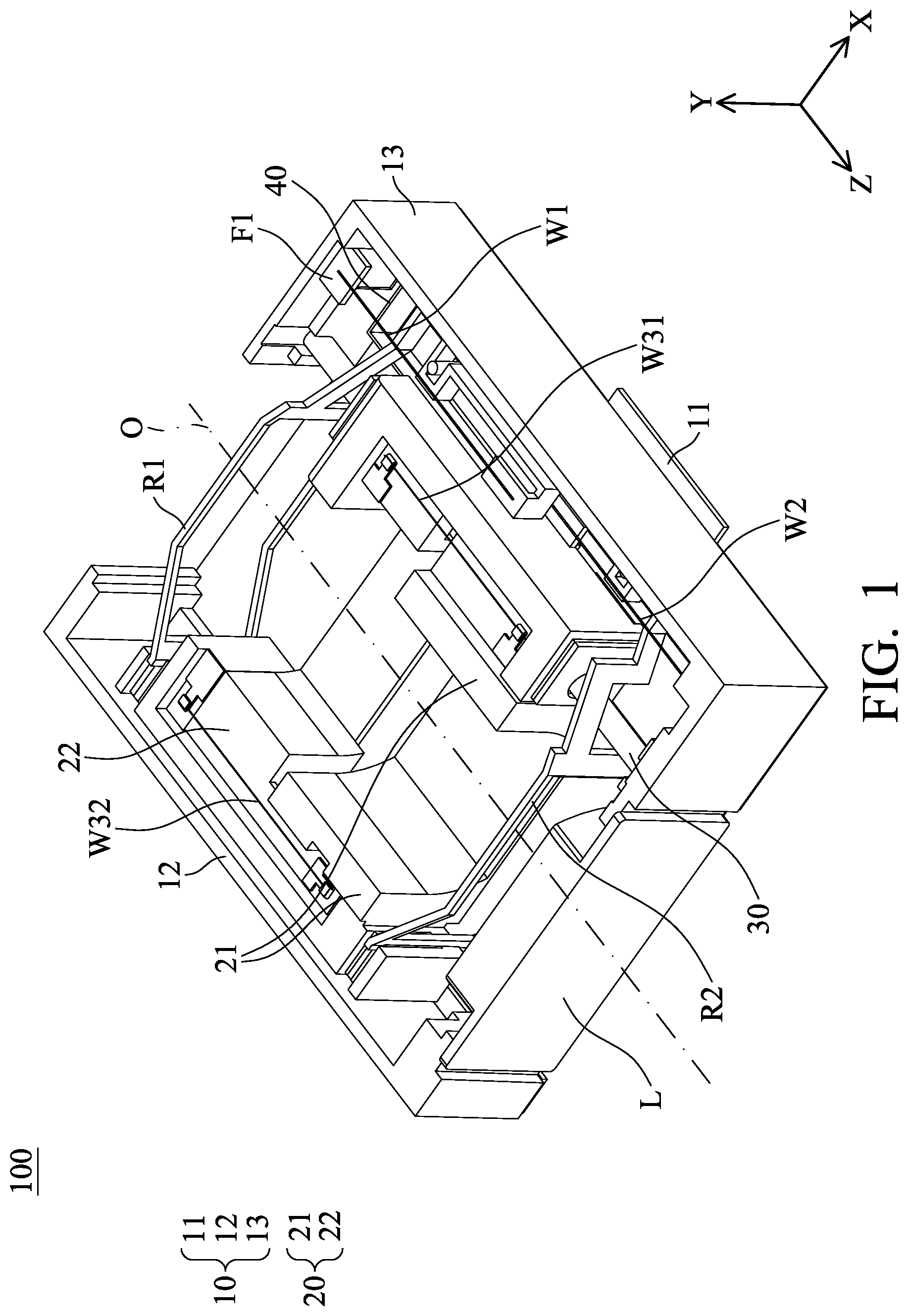
is a perspective diagram of a driving mechanism 100 in accordance with an embodiment of the invention.
is a perspective diagram of the driving mechanism 100 in with the lens L and the sidewalls 12 and 13 omitted therefrom.
are perspective diagrams of the driving mechanism 100 in with the lens L, the fixed part 10 , and the circuit unit 40 omitted therefrom.
is a perspective diagram of the bottom plate 11 , the circuit unit 40 , the first slider 21 , the first and second connecting members R 1 and R 2 , and the hinges P 1 and P 2 in .
is a perspective diagram of the circuit unit 40 in .
is a perspective diagram of the first and second connecting members R 1 and R 2 .
is a top view showing the first connecting member R 1 impels the first slider 21 in the −Z direction (the first direction D 1 ) relative to the fixed part 10 when the first wire W 1 contracts in length.
is a top view showing the second connecting member R 2 impels the first slider 21 in the Z direction (the second direction D 2 ) relative to the fixed part 10 when the second wire W 2 contracts in length.
is a cross-sectional view of the driving mechanism 100 in .
is a perspective diagram of a driving mechanism that has a circuit unit 50 , in accordance with another embodiment of the invention.
is a perspective diagram of the circuit unit 50 in .
DETAILED DESCRIPTION OF INVENTION
The making and using of the embodiments of the driving mechanism are discussed in detail below. It should be appreciated, however, that the embodiments provide many applicable inventive concepts that can be embodied in a wide variety of specific contexts. The specific embodiments discussed are merely illustrative of specific ways to make and use the embodiments, and do not limit the scope of the disclosure.
Unless defined otherwise, all technical and scientific terms used herein have the same meaning as commonly understood by one of ordinary skill in the art to which this invention belongs. It should be appreciated that each term, which is defined in a commonly used dictionary, should be interpreted as having a meaning conforming to the relative skills and the background or the context of the present disclosure, and should not be interpreted in an idealized or overly formal manner unless defined otherwise.
In the following detailed description of the preferred embodiments, reference is made to the accompanying drawings, and in which specific embodiments of which the invention may be practiced are shown by way of illustration. In this regard, directional terminology, such as “top,” “bottom,” “left,” “right,” “front,” “back,” etc., is used with reference to the orientation of the figures being described. The components of the present invention can be positioned in a number of different orientations. As such, the directional terminology is used for the purposes of illustration and is in no way limiting.
is a perspective diagram of a driving mechanism 100 in accordance with an embodiment of the invention. is a perspective diagram of the driving mechanism 100 in with the lens L and the sidewalls 12 and 13 omitted therefrom. are perspective diagrams of the driving mechanism 100 in with the lens L, the fixed part 10 , and the circuit unit 40 omitted therefrom.
Referring to , the driving mechanism 100 in this embodiment may be disposed in a camera device, and it primarily includes a fixed part 10 , a movable part 20 , a shaft 30 , a circuit unit 40 , a first connecting member R 1 , a second connecting member R 2 , a first wire W 1 , a second wire W 2 , and two third wires W 31 and W 32 . The first and second connecting members R 1 and R 2 have an L-shaped structure, and the first, second, and third wires W 1 , W 2 , W 31 , and W 32 comprise Shape Memory Alloy (SMA) material.
In this embodiment, the fixed part 10 has a bottom plate 11 and two sidewalls 12 and 13 extending from the bottom plate 11 in the Y direction. The circuit unit 40 is affixed to the bottom plate 11 and/or the sidewall 13 for electrically connecting to the first and second wires W 1 and W 2 . Additionally, the movable part 20 includes a first slider 21 and a second slider 22 . The shaft 30 extends through the first and second sliders 21 and 22 and is affixed to opposite ends of the sidewall 13 . Hence, the movable part 20 can be guided by the shaft 30 to slide relative to the fixed part 10 along the Z axis.
As shown in , a lens L is disposed at an end of the fixed part 10 . The lens L, the first slider 21 , and the second slider 22 are arranged along the Z axis. In this embodiment, one or several optical elements (not shown) may be disposed on the first and second sliders 21 and 22 , and the optical axis 0 of these optical elements (e.g. optical lenses) extends through the lens L.
It should be noted that the first and second connecting members R 1 and R 2 are hinged on the bottom plate 11 via the hinges P 1 and P 2 ( ), and the ends of the first and second connecting members R 1 and R 2 are affixed to opposite sides of the first slider 21 . Moreover, two metal parts F 1 and F 2 are affixed to opposite ends of the sidewall 13 , wherein the first wire W 1 is connected between the metal part F 1 and the first connecting member R 1 , and the second wire W 2 is connected between the metal part F 2 and the second connecting member R 2 .
When a current signal is applied to the first wire W 1 , the first wire W 1 contracts in length and forces the first slider 21 to move relative to the fixed part 10 in the −Z direction (the first direction D 1 ) via the first connecting member R 1 . In contrast, when a current signal is applied to the second wire W 2 , the second wire W 2 contracts in length and forces the first slider 21 to move relative to the fixed part 10 in the Z direction (the second direction D 2 ) via the second connecting member R 2 .
Additionally, the two third wires W 31 and W 32 are connected between the first slider 21 and the second slider 22 that is movably received in the first slider 21 . When a current signal is applied to the third wire W 31 , the third wire W 31 contracts in length and forces the second slider 22 to move relative to the first slider 21 in the Z direction (the second direction D 2 ). In contrast, when a current signal is applied to the third wire W 32 , the third wire W 32 contracts in length and forces the second slider 22 to move relative to the first slider 21 in the −Z direction (the first direction D 1 ).
is a perspective diagram of the bottom plate 11 , the circuit unit 40 , the first slider 21 , the first and second connecting members R 1 and R 2 , and the hinges P 1 and P 2 in . is a perspective diagram of the circuit unit 40 in .
As shown in , the circuit unit 40 in this embodiment may comprise a PCB, FPC or other circuit structure produced by insert molding or LDS technology. The circuit unit 40 primarily has an L-shaped base portion 41 , an L-shaped side portion 42 , and an L-shaped bent portion 43 connected between the side portion 42 and the first slider 21 .
In this embodiment, the base portion 41 is affixed to the bottom plate 11 , and the side portion 42 is connected between the base portion 41 and the bent portion 43 , wherein the side portion 42 and the bent portion 43 are perpendicular to the base portion 41 . Referring to , two IC elements C 1 and C 2 are disposed on the base portion 41 .
The bent portion 43 has a surface 431 in contact with a conductive terminal on the lateral side 211 of the first slider 21 ( ). When the first slider 21 slides along the Z axis relative to the bottom plate 11 , the surface 431 remains in contact with the conductive terminal.
Therefore, the third wires W 31 and W 32 can be electrically connected to the IC elements C 1 and C 2 on the base portion 41 of the circuit unit 40 through the metal traces embedded in the first slider 21 and the conductive terminals on the lateral side 211 . The circuit unit 40 can be further connected to an external circuit through the circuit structure (not shown) formed on the bottom plate 11 .
Still referring to , an opening 401 is formed between the base portion 41 and the side portion 42 , and the hinges P 1 and P 2 extend through the opening 401 and connect to the bottom plate 11 . Hence, the first and second connecting members R 1 and R 2 can be pivotally connected to the bottom plate 11 via the hinges P 1 and P 2 .
is a perspective diagram of the first and second connecting members R 1 and R 2 . is a top view showing the first connecting member R 1 impels the first slider 21 in the −Z direction (the first direction D 1 ) relative to the fixed part 10 when the first wire W 1 contracts in length. is a top view showing the second connecting member R 2 impels the first slider 21 in the Z direction (the second direction D 2 ) relative to the fixed part 10 when the second wire W 2 contracts in length.
As shown in , the first connecting member R 1 has a connection end R 11 , a free end R 12 , a U-shaped pivot portion R 13 , a resistance arm V 11 , and an effort arm V 12 . The resistance arm V 11 has a bent structure connecting the pivot portion R 13 to the connection end R 11 . The effort arm V 12 connects the pivot portion R 13 to the free end R 12 , and the resistance arm V 11 is longer than the effort arm V 12 .
Similarly, the second connecting member R 2 has a connection end R 21 , a free end R 22 , a U-shaped pivot portion R 23 , a resistance arm V 21 and an effort arm V 22 . The resistance arm V 21 has a bent structure connecting the pivot portion R 23 to the connection end R 21 . The effort arm V 22 connects the pivot portion R 23 to the free end R 22 , and the resistance arm V 21 is longer than the effort arm V 22 .
Specifically, the resistance arm V 11 forms a hole h 1 , and the resistance arm V 21 forms a hole h 2 , thereby increasing the flexibility and reducing the weight of the resistance arms V 11 and V 21 . Moreover, the optical axis O of the optical elements extends through the holes h 1 and h 2 , so that light would not be blocked by the resistance arms V 11 and V 21 . In some embodiments, the resistance arms V 11 and V 21 may have a C-shaped or U-shaped structure, so that the resistance arms V 11 and V 21 can be longer than the distance from the connection ends R 11 , R 21 to the hinges P 1 , P 2 along the X axis. Thus, the moving distance of the first slider 21 can be increased, and the resistance arms V 11 and V 21 can be more resilient to increase structural reliability of the first and second connecting members R 1 and R 2 .
In , the connection end R 11 is affixed to a first end of the first slider 21 , and the hinge P 1 is received in the pivot portion R 13 . The two ends of the first wire W 1 are respectively mounted on the free end R 12 and the metal part F 1 by soldering or welding, wherein the distance between the first wire W 1 and the hinge P 1 is shorter than the distance between the connection end R 11 and the hinge P 1 .
When a current signal is applied to the first wire W 1 , the first wire W 1 contracts in length and forces the first connecting member R 1 to rotate clockwise around the hinge P 1 . Hence, the first slider 21 can be forced to move relative to the fixed part 10 in the −Z direction (the first direction D 1 ) by the first connecting member R 1 , as indicated by the arrow in .
Similarly, as shown in , the connection end R 21 is affixed to a second end of the first slider 21 (opposite to the first end), and the hinge P 2 is received in the pivot portion R 23 . The two ends of the second wire W 2 are respectively mounted on the free end R 22 and the metal part F 2 by soldering or welding, wherein the distance between the second wire W 2 and the hinge P 2 is shorter than the distance between the connection end R 21 and the hinge P 2 .
When a current signal is applied to the second wire W 2 , the second wire W 2 contracts in length and forces the second connecting member R 2 to rotate counterclockwise around the hinge P 2 . Hence, the first slider 21 can be forced to move relative to the fixed part 10 in the Z direction (the second direction D 2 ) by the second connecting member R 2 , as indicated by the arrow in .
In this embodiment, the first and second connecting members R 1 and R 2 are disposed on opposite sides of the first slider 21 . When the first wire W 1 or the second wire W 2 contracts, the first slider 21 can be impelled either in the −Z direction or in the Z direction by the first and second connecting members R 1 and R 2 , thereby achieving rapid and accurate positioning of the first slider 21 .
It should be noted that the first and second wires W 1 and W 2 are located between the hinge P 1 , P 2 and the shaft 30 along the X axis (the first axis), thus achieving effective space utilization of the driving mechanism 100 and facilitating miniaturization of the product.
For example, the first and second connecting members R 1 , R 2 and the hinges P 1 , P 2 may comprise metal, whereby the first and second wires W 1 and W 2 can be electrically connected to the circuit structure on the bottom plate 11 via the first and second connecting members R 1 , R 2 and the hinges P 1 , P 2
In this embodiment, the shaft 30 is parallel to the axis O and located between the hinges P 1 , P 2 and the connection ends R 11 , R 21 along the X axis (the first axis). Moreover, when viewed along the Y axis (the second axis) that is perpendicular to the optical axis O of the optical elements, the first and second connecting members R 1 and R 2 partially overlap, thereby achieving effective space utilization of the driving mechanism 100 and facilitating miniaturization of the product.
is a cross-sectional view of the driving mechanism 100 in . As shown in , the shaft 30 extends through a hole of the first slider 21 . Several rollers B are disposed in the hole and connected between the shaft 30 and the first slider 21 , thereby improving the stability of the first slider 21 when sliding along the shaft 30 .
Still referring to , a magnet HM is disposed at the bottom of the first slider 21 , and the IC element C 2 (e.g. Hall effect sensor) on the base portion 41 of the circuit unit 40 can detect the magnet HM, whereby the displacement of the first slider 21 relative to the bottom plate 11 can be determined.
is a perspective diagram of a driving mechanism that has a circuit unit 50 , in accordance with another embodiment of the invention. is a perspective diagram of the circuit unit 50 in .
Referring to , the circuit unit 50 can replace the circuit unit 40 in . In this embodiment, the circuit unit 50 may be a metal truss that comprises a rectangular outer frame 51 , a rectangular inner frame 52 , and four rods 53 connected between the outer and inner frames 51 and 52 . The outer frame 51 is affixed to the sidewall 13 of the fixed part 10 , and the inner frame 52 can slide and contact a conductive terminal (not shown) on the lateral side 211 of the first slider 21 . When the first slider 21 moves along the Z axis relative to the bottom plate 11 , the inner frame 52 remains in contact with the conductive terminal.
Therefore, the third wires W 31 and W 32 can be electrically connected to the circuit structure on the bottom plate 11 through the circuit unit 50 and the metal traces formed on the first slider 21 .
In summary, the invention provides a driving mechanism that includes the first and second connecting members R 1 , R 2 and the wires W 1 , W 2 , W 31 , and W 32 , wherein the wires W 1 , W 2 , W 31 , and W 32 comprise Shape Memory Alloy (SMA) material. By applying principle of leverage, the first and second sliders 21 and 22 and the optical elements disposed thereon can be impelled in a direction parallel to the optical axis O by the first and second connecting members R 1 , R 2 , thus improving efficiency of the driving mechanism and facilitating miniaturization of the product.
Although some embodiments of the present disclosure and their advantages have been described in detail, it should be understood that various changes, substitutions and alterations can be made herein without departing from the spirit and scope of the disclosure as defined by the appended claims. For example, it will be readily understood by those skilled in the art that many of the features, functions, processes, and materials described herein may be varied while remaining within the scope of the present disclosure. Moreover, the scope of the present application is not intended to be limited to the particular embodiments of the process, machine, manufacture, compositions of matter, means, methods and steps described in the specification. As one of ordinary skill in the art will readily appreciate from the disclosure of the present disclosure, processes, machines, manufacture, compositions of matter, means, methods, or steps, presently existing or later to be developed, that perform substantially the same function or achieve substantially the same result as the corresponding embodiments described herein may be utilized according to the present disclosure. Accordingly, the appended claims are intended to include within their scope such processes, machines, manufacture, compositions of matter, means, methods, or steps. Moreover, the scope of the appended claims should be accorded the broadest interpretation so as to encompass all such modifications and similar arrangements.
While the invention has been described by way of example and in terms of preferred embodiment, it should be understood that the invention is not limited thereto. On the contrary, it is intended to cover various modifications and similar arrangements (as would be apparent to those skilled in the art). Therefore, the scope of the appended claims should be accorded the broadest interpretation to encompass all such modifications and similar arrangements.
Figures (12)
Citations
This patent cites (3)
- US2015/0212291
- US2020/0041872
- US2024/0276088