Abstract
A transformer includes a magnetic core set and 2N pairs of windings. The magnetic core set includes a first magnetic core, a second magnetic core, a first magnetic column, and a second magnetic column. Each of the pairs of windings includes a high-voltage side winding and a low-voltage side winding. Each of the pairs of the windings surrounds one of the first and the second magnetic columns. The surrounding direction of the high-voltage side windings surrounding the first magnetic core is opposite to the surrounding direction of the high-voltage side windings surrounding the second magnetic core.
Claims (20)
1. A transformer, comprising: a magnetic core set, comprising: a first magnetic core; a second magnetic core, parallel to the first magnetic core; and a magnetic column pair, comprising a first magnetic column and a second magnetic column, the first magnetic column being substantially parallel to the second magnetic column, wherein the first magnetic column and the second magnetic column are between the first magnetic core and the second magnetic core, and a number of the magnetic columns is two; and 2N winding pairs, wherein N is a positive integer greater than or equal to 2, each of the winding pairs comprises a high-voltage side winding and a low-voltage side winding, each of the winding pairs surrounds one of the first magnetic column and the second magnetic column, and a first winding direction in which the high-voltage side windings surround the first magnetic column is substantially opposite to a second winding direction in which the high-voltage side windings surround the second magnetic column, and outer sides of the first magnetic core and the second magnetic core are aligned with or protrude from outer sides of the 2N winging pairs.
Show 19 dependent claims
2. The transformer according to claim 1 , wherein the high-voltage side windings are connected in series sequentially.
3. The transformer according to claim 2 , wherein each of the low-voltage side windings comprises a plurality of low-voltage side sub-windings, and the low-voltage side sub-windings are connected in parallel.
4. The transformer according to claim 3 , wherein a number of the winding pairs surrounding the first magnetic column is the same as a number of the winding pairs surrounding the second magnetic column.
5. The transformer according to claim 2 , wherein a number of the winding pairs surrounding the first magnetic column is the same as a number of the winding pairs surrounding the second magnetic column.
6. The transformer according to claim 1 , further comprising a circuit board, wherein the circuit board comprises a plurality of winding layers, each of the winding layers comprises a winding, and the high-voltage side windings and the low-voltage side windings are respectively the windings of the plurality of winding layers.
7. The transformer according to claim 6 , wherein N is equal to 2, the high-voltage side windings are connected in series sequentially, each of the low-voltage side windings comprises a plurality of low-voltage side sub-windings, and the low-voltage side sub-windings are connected in parallel.
8. The transformer according to claim 6 , wherein each of the low-voltage side windings comprises a plurality of low-voltage side sub-windings, and the low-voltage side sub-windings are connected in parallel.
9. The transformer according to claim 8 , wherein a number of the winding pairs surrounding the first magnetic column is the same as a number of the winding pairs surrounding the second magnetic column.
10. The transformer according to claim 6 , wherein N is equal to 3, the winding pairs surrounding the first magnetic column are sequentially a first winding pair, a second winding pair, and a third winding pair in a long axial direction of the first magnetic column, the winding pairs surrounding the second magnetic column are sequentially a sixth winding pair, a fifth winding pair, and a fourth winding pair in a long axial direction of the second magnetic column, the long axial direction of the first magnetic column and the long axial direction of the second magnetic column are parallel and in a same direction, and the high-voltage side windings of the first winding pair, the second winding pair, the third winding pair, the fourth winding pair, the fifth winding pair, and the sixth winding pair are connected in series sequentially.
11. The transformer according to claim 6 , wherein N is equal to 3, the winding pairs surrounding the first magnetic column are sequentially a first winding pair, a second winding pair, and a third winding pair in a long axial direction of the first magnetic column, the winding pairs surrounding the second magnetic column are sequentially a sixth winding pair, a fifth winding pair, and a fourth winding pair in a long axial direction of the second magnetic column, the long axial direction of the first magnetic column and the long axial direction of the second magnetic column are parallel and in a same direction, and the high-voltage side windings of the first winding pair, the sixth winding pair, the fifth winding pair, the second winding pair, the third winding pair, and the fourth winding pair are connected in series sequentially.
12. The transformer according to claim 6 , further comprising a high-voltage side circuit and a low-voltage side circuit, wherein N is equal to 2, the four winding pairs are respectively a first winding pair, a second winding pair, a third winding pair, and a fourth winding pair, each of the winding pairs comprises a high-voltage side winding and two low-voltage side windings, the high-voltage side winding of the first winding pair and the high-voltage side winding of the second winding pair are connected in series to form a first high-voltage side winding string, the high-voltage side winding of the third winding pair and the high-voltage side winding of the fourth winding pair are connected in series to form a second high-voltage side winding string, the first high-voltage side winding string and the second high-voltage side winding string are connected in parallel and then electrically connected to the high-voltage side circuit, and the two low-voltage side windings of each of the winding pairs are electrically connected to the low-voltage side circuit separately.
13. The transformer according to claim 12 , wherein a number of the winding pairs surrounding the first magnetic column is the same as a number of the winding pairs surrounding the second magnetic column.
14. The transformer according to claim 1 , further comprising: a high-voltage side circuit, electrically connected to the high-voltage side windings, wherein the high-voltage side circuit is adapted to receive a power source to output an alternating current to the high-voltage side windings; and a plurality of low-voltage side circuits, electrically connected to the low-voltage side windings separately, wherein each of the low-voltage side circuits comprises a synchronous rectifier and a voltage stabilizing circuit, each of the synchronous rectifiers is connected in series to the corresponding low-voltage side winding, and each of the voltage stabilizing circuits is connected in parallel with the corresponding low-voltage side winding.
15. The transformer according to claim 1 , wherein the high-voltage side windings and the low-voltage side windings are wires in a copper wire form.
16. The transformer according to claim 15 , wherein N is equal to 2, the high-voltage side windings are connected in series sequentially, each of the low-voltage side windings comprises a plurality of low-voltage side sub-windings, and the low-voltage side sub-windings are connected in parallel.
17. The transformer according to claim 15 , wherein each of the low-voltage side windings comprises a plurality of low-voltage side sub-windings, and the low-voltage side sub-windings are connected in parallel.
18. The transformer according to claim 15 , wherein N is equal to 3, the winding pairs surrounding the first magnetic column are sequentially a first winding pair, a second winding pair, and a third winding pair in a long axial direction of the first magnetic column, the winding pairs surrounding the second magnetic column are sequentially a sixth winding pair, a fifth winding pair, and a fourth winding pair in a long axial direction of the second magnetic column, the long axial direction of the first magnetic column and the long axial direction of the second magnetic column are parallel and in a same direction, and the high-voltage side windings of the first winding pair, the second winding pair, the third winding pair, the fourth winding pair, the fifth winding pair, and the sixth winding pair are connected in series sequentially.
19. The transformer according to claim 15 , wherein N is equal to 3, the winding pairs surrounding the first magnetic column are sequentially a first winding pair, a second winding pair, and a third winding pair in a long axial direction of the first magnetic column, the winding pairs surrounding the second magnetic column are sequentially a sixth winding pair, a fifth winding pair, and a fourth winding pair in a long axial direction of the second magnetic column, the long axial direction of the first magnetic column and the long axial direction of the second magnetic column are parallel and in a same direction, and the high-voltage side windings of the first winding pair, the sixth winding pair, the fifth winding pair, the second winding pair, the third winding pair, and the fourth winding pair are connected in series sequentially.
20. The transformer according to claim 1 , wherein a number of the winding pairs surrounding the first magnetic column is the same as a number of the winding pairs surrounding the second magnetic column.
Full Description
Show full text →
CROSS-REFERENCES TO RELATED APPLICATIONS
This non-provisional application claims priority under 35 U.S.C. § 119(a) to Patent Application No. 109132176 filed in Taiwan, R.O.C. on Sep. 17, 2020 and Patent Application No. 110130180 filed in Taiwan, R.O.C. on Aug. 16, 2021, the entire contents of which are hereby incorporated by reference.
BACKGROUND
Technical Field
The present invention relates to a transformer, and in particular, to a transformer with a plurality of low-voltage side windings.
Related Art
A transformer is adapted to adjust an input voltage to a required voltage. In some applications, the transformer is used to convert a high-voltage input voltage into a low-voltage output voltage. This type of transformer includes a high-voltage side coil and a low-voltage side coil. The number of turns of windings of the high-voltage side coil is greater than that of the low-voltage side coil. The high-voltage side coil receives a high-voltage input voltage to generate a magnetic field, and the low-voltage side coil generates a low-voltage output voltage in response to the magnetic field. A voltage ratio of the input voltage to the output voltage corresponds to a turns ratio of windings of the high-voltage side coil to the low-voltage side coil.
In different application scenarios, a single transformer includes a plurality of sets of high-voltage side coils and low-voltage side coils. The plurality of sets of high-voltage side coils and low-voltage side coils are integrated into a single transformer. The volume of the transformer is relatively large.
SUMMARY
In view of this, according to some embodiments, a transformer includes a magnetic core set and 2N winding pairs. The magnetic core set includes a first magnetic core, a second magnetic core, and a magnetic column pair. The second magnetic core is parallel to the first magnetic core. The magnetic column pair includes a first magnetic column and a second magnetic column. The first magnetic column is substantially parallel to the second magnetic column. The first magnetic column and the second magnetic column are between the first magnetic core and the second magnetic core. N is a positive integer greater than or equal to 2. Each of the winding pairs includes a high-voltage side winding and a low-voltage side winding. Each of the winding pairs surrounds one of the first magnetic column and the second magnetic column. A first winding direction in which the high-voltage side windings surround the first magnetic column is substantially opposite to a second winding direction in which the high-voltage side windings surround the second magnetic column.
According to some embodiments, the high-voltage side windings are connected in series sequentially, each of the low-voltage side windings includes a plurality of low-voltage side sub-windings, and the low-voltage side sub-windings are connected in parallel.
According to some embodiments, the transformer further includes a circuit board, where the circuit board includes a plurality of winding layers, each of the winding layers includes a winding, and the high-voltage side winding and the low-voltage side winding of at least one of the winding pairs are respectively the windings.
According to some embodiments, N is equal to 2, the high-voltage side windings are connected in series sequentially, each of the low-voltage side windings includes a plurality of low-voltage side sub-windings, and the low-voltage side sub-windings are connected in parallel.
According to some embodiments, the winding pairs surrounding the first magnetic column are sequentially a first winding pair, a second winding pair, and a third winding pair in a long axial direction of the first magnetic column, the winding pairs surrounding the second magnetic column are sequentially a sixth winding pair, a fifth winding pair, and a fourth winding pair in a long axial direction of the second magnetic column, the long axial direction of the first magnetic column and the long axial direction of the second magnetic column are parallel and in a same direction, and the high-voltage side windings of the first winding pair, the second winding pair, the third winding pair, the fourth winding pair, the fifth winding pair, and the sixth winding pair are connected in series sequentially.
According to some embodiments, the winding pairs surrounding the first magnetic column are sequentially a first winding pair, a second winding pair, and a third winding pair in a long axial direction of the first magnetic column, the winding pairs surrounding the second magnetic column are sequentially a sixth winding pair, a fifth winding pair, and a fourth winding pair in a long axial direction of the second magnetic column, the long axial direction of the first magnetic column and the long axial direction of the second magnetic column are parallel and in a same direction, and the high-voltage side windings of the first winding pair, the sixth winding pair, the fifth winding pair, the second winding pair, the third winding pair, and the fourth winding pair are connected in series sequentially.
In summary, according to some embodiments, the transformer includes 2N winding pairs, and each of the winding pairs surrounds the first magnetic column or the second magnetic column. With this structure, the 2N winding pairs can be effectively integrated into the magnetic core set including the first magnetic column and the second magnetic column, so that the volume of the transformer is reduced.
BRIEF DESCRIPTION OF THE DRAWINGS
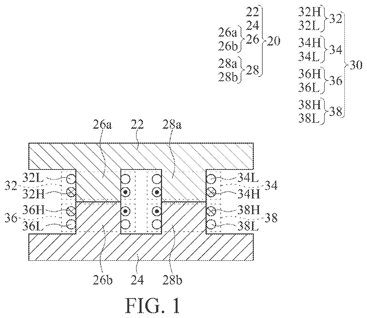
illustrates a schematic cross-sectional view of a transformer according to some embodiments;
illustrates a circuit functional block diagram of a transformer according to some embodiments;
illustrates a three-dimensional exploded view of a copper-wire transformer according to some embodiments;
illustrates a three-dimensional exploded view of a planar transformer according to some embodiments;
illustrates a circuit functional block diagram of a transformer according to some embodiments;
illustrates a schematic diagram of a side structure of a planar transformer implementing the circuit block diagram of according to some embodiments;
A illustrates a circuit functional block diagram of a transformer according to some embodiments;
B illustrates a circuit functional block diagram of a transformer according to some embodiments;
illustrates a schematic diagram of a side structure of a planar transformer implementing the circuit block diagram of according to some embodiments; and
illustrates a schematic cross-sectional view of a transformer according to some embodiments.
DETAILED DESCRIPTION
illustrates a schematic cross-sectional view of a transformer according to some embodiments. The transformer includes a magnetic core set 20 and 2N winding pairs 30 . The magnetic core set 20 includes a first magnetic core 22 , a second magnetic core 24 , and a magnetic column pair 26 , 28 . The second magnetic core 24 is parallel to the first magnetic core 22 . The magnetic column pair 26 , 28 includes a first magnetic column 26 and a second magnetic column 28 , the first magnetic column 26 is substantially parallel to the second magnetic column 28 , and the first magnetic column 26 and the second magnetic column 28 are located between the first magnetic core 22 and the second magnetic core 24 . N is a positive integer greater than or equal to 2 (N in the embodiments of is equal to 2). Each of the winding pairs 32 , 34 , 36 , and 38 includes high-voltage side windings 32 H, 34 H, 36 H, and 38 H, and low-voltage side windings 32 L, 34 L, 36 L, and 38 L. Each of the winding pairs 32 , 34 , 36 , and 38 surrounds one of the first magnetic column 26 and the second magnetic column 28 (that is, surrounds the first magnetic column 26 or the second magnetic column 28 ). A first winding direction in which the high-voltage side windings 32 H and 36 H surround the first magnetic column 26 is substantially opposite to a second winding direction in which the high-voltage side windings 34 H and 38 H surround the second magnetic column 28 .
Specifically, the high-voltage side windings 32 H, 34 H, 36 H, and 38 H in are respectively a first high-voltage side winding 32 H, a second high-voltage side winding 34 H, a third high-voltage side winding 36 H, and a fourth high-voltage side winding 38 H. From the view of , the (first) winding direction in which the first high-voltage side winding 32 H and the third high-voltage side winding 36 H surround the first magnetic column 26 is to come out of the page from the right side of the first magnetic column 26 and go into the page from the left side of the first magnetic column 26 . Similarly, the (second) winding direction in which the second high-voltage side winding 34 H and the fourth high-voltage side winding 38 H surround the second magnetic column 28 is to come out of the page from the left side of the second magnetic column 28 and go into the page from the right side of the second magnetic column 28 . Therefore, the first winding direction in which the first and third high-voltage side windings 32 H and 36 H surround the first magnetic column 26 is substantially opposite to the second winding direction in which the second and fourth high-voltage side windings 34 H and 38 H surround the second magnetic column 28 . In some embodiments, a number of the winding pairs 32 and 36 surrounding the first magnetic column 26 is the same as a number of the winding pairs 34 and 38 surrounding the second magnetic column 28 . For example, in the embodiments of , the number of the winding pairs 32 and 36 surrounding the first magnetic column 26 is 2, and the number of the winding pairs 34 and 38 surrounding the second magnetic column 28 is also 2. The winding direction of the first high-voltage side winding 32 H may be the direction in which the electrical current flows or the direction from one end to the other end of the first high-voltage side winding 32 H. Likewise, the winding directions of the high-voltage side windings 34 H, 36 H, 38 H may be determined by the electrical current or two ends of each of the high-voltage side windings 34 H, 36 H, 38 H.
Although the first winding direction and the second winding direction in the embodiments of are as described above, the first winding direction and the second winding direction may alternatively be reversed, that is, the first winding direction is to come out of the page from the left side of the first magnetic column 26 and go into the page from the right side of the first magnetic column 26 ; and the second winding direction is to come out of the page from the right side of the second magnetic column 28 and go into the page from the left side of the second magnetic column 28 . Besides, does not illustrate winding directions of the low-voltage side windings 32 L, 34 L, 36 L, and 38 L. It indicates that the winding directions of the low-voltage side windings 32 L, 34 L, 36 L, and 38 L may be determined according to requirements.
Therefore, based on the foregoing embodiment, when the transformer receives an alternating current (input voltage), a direction of magnetic flux generated by the high-voltage side windings 32 H and 36 H surrounding the first magnetic column 26 is opposite to that of magnetic flux generated by the high-voltage side windings 34 H and 38 H surrounding the second magnetic column 28 . Therefore, the transformer forms a closed magnetic circuit by means of the first magnetic core 22 , the first magnetic column 26 , the second magnetic core 24 , and the second magnetic column 28 . The low-voltage side windings 32 L, 34 L, 36 L, and 38 L each generate a corresponding induced current in response to the magnetic circuit. The induced current passes through a low-voltage side circuit (described later), and the transformer may output a corresponding output voltage. A ratio of the input voltage to the output voltage corresponds to a turn ratio of the high-voltage side windings 32 H, 34 H, 36 H, and 38 H to the low-voltage side windings 32 L, 34 L, 36 L, and 38 L.
In some embodiments, the magnetic core set 20 includes only a magnetic column pair 26 , 28 , and the magnetic column pair 26 , 28 is formed by a first magnetic column 26 and a second magnetic column 28 , that is, the magnetic column pair 26 , 28 only includes the first magnetic column 26 and the second magnetic column 28 . The high-voltage side windings 32 H, 34 H, 36 H, and 38 H and the low-voltage side windings 32 L, 34 L, 36 L, and 38 L surround the corresponding first magnetic column 26 or second magnetic column 28 . In this way, the 2N winding pairs 30 surround the two magnetic columns 26 and 28 , and achieve a voltage conversion effect, so that the volume of the entire transformer is significantly reduced.
In the embodiments shown in , the first magnetic column 26 includes two first magnetic sub-columns 26 a and 26 b , and the first magnetic sub-columns 26 a and 26 b are substantially coaxially arranged between the first magnetic core 22 and the second magnetic core 24 . The second magnetic column 28 includes two second magnetic sub-columns 28 a and 28 b , and the second magnetic sub-columns 28 a and 28 b are substantially coaxially arranged between the first magnetic core 22 and the second magnetic core 24 . However, the present disclosure is not limited thereto, and each of the first magnetic column 26 and the second magnetic column 28 may be a single column, as shown in .
In some embodiments, as shown in , the first magnetic sub-column 26 a , the first magnetic core 22 , and the second magnetic sub-column 28 a are integrated as a single-piece component. The first magnetic sub-column 26 b , the second magnetic core 24 , and the second magnetic sub-column 28 b are integrated into a single-piece component. However, the present disclosure is not limited thereto, and the first magnetic sub-columns 26 a and 26 b , the second magnetic sub-columns 28 a and 28 b , the first magnetic core 22 , and the second magnetic core 24 may be separate components.
In some embodiments, the first magnetic core 22 , the first magnetic column 26 , the second magnetic core 24 , and the second magnetic column 28 form a ring area, the central part of the hatching area which excludes the four horizontal extended portions in . The ring area may be closed or open (non-closed). For example, the two first magnetic sub-columns 26 a and 26 b are substantially coaxially arranged with a spacing therebetween, and the two second magnetic sub-columns 28 a and 28 b are substantially coaxially arranged with a spacing therebetween. In addition, in the embodiment in which the first magnetic sub-columns 26 a and 26 b , the second magnetic sub-columns 28 a and 28 b , the first magnetic core 22 , and the second magnetic core 24 are separate components, one of two adjacent components may be in contact or have a spacing from the other of the adjacent components. For example, the first magnetic core 22 and the first magnetic sub-column 26 a are in contact or have a spacing from each other. The first magnetic core 22 and the second magnetic sub-column 28 a are in contact or have a spacing from each other. The second magnetic core 24 and the first magnetic sub-column 26 b are in contact or have a spacing from each other. The second magnetic core 24 and the second magnetic sub-column 28 b are in contact or have a spacing from each other. The spacings may be the same or different.
In the embodiments of , outer sides (left and right sides of ) of the first magnetic core 22 and the second magnetic core 24 protrude from outer sides (left and right sides of ) of the 2N winding pairs 30 , but the present disclosure is not limited thereto. The outer sides of the first magnetic core 22 and the second magnetic core 24 may be aligned with the outer sides of the 2N winding pairs 30 (left and right sides of the winding pairs in , that is, a leftmost side and a rightmost side of the dashed line in ), or may be aligned with outer side surfaces of the magnetic column pair 26 , 28 (left and right sides of the magnetic column pair in , that is, a left side of the first magnetic column 26 and a right side of the second magnetic column 28 ).
The high-voltage side windings 32 H, 34 H, 36 H, and 38 H may have a series relationship, a parallel relationship, or a series-parallel relationship; and the low-voltage side windings 32 L, 34 L, 36 L, and 38 L may have a series relationship, a parallel relationship, or a series-parallel relationship (detailed later). In addition, the number of the 2N winding pairs 30 may also vary depending on requirements of the transformer (for example, an output current or a number of output ports). For example, N may be 3, 4, or 5, which is illustrated later.
illustrates a circuit functional block diagram of a transformer according to some embodiments. The transformer includes a high-voltage side circuit 90 and a low-voltage side circuit 92 . In this embodiment, the transformer includes four low-voltage side circuits 92 a , 92 b , 92 c , and 92 d . The high-voltage side circuit 90 is adapted to receive an input power source 94 , and the input power source 94 may be a direct current power source (as shown in ) or an alternating current power source. The high-voltage side circuit 90 is adapted to convert the input power source 94 into a predetermined alternating current and then input the alternating current into the high-voltage side windings 32 H, 34 H, 36 H, and 38 H. After the high-voltage side windings 32 H, 34 H, 36 H, and 38 H receive the alternating current, the low-voltage side windings 32 L, 34 L, 36 L, and 38 L generate induced currents. The low-voltage side circuits 92 a , 92 b , 92 c , and 92 d rectify the induced currents and output the rectified induced currents to a load. Each of the low-voltage side circuits 92 a , 92 b , 92 c , and 92 d includes a synchronous rectifier 98 a and a voltage stabilizing circuit 98 b (only the first low-voltage side circuit 92 a is used as an example in to illustrate a detailed circuit thereof). The synchronous rectifier 98 a is connected in series to the corresponding low-voltage side winding 32 L, and the voltage stabilizing circuit 98 b is connected in parallel to the corresponding low-voltage side winding 32 L.
In the embodiments of , the high-voltage side windings 32 H, 34 H, 36 H, and 38 H are connected in series sequentially, while each of the low-voltage side windings 32 L, 34 L, 36 L, and 38 L has an independent output. The low-voltage side windings 32 L, 34 L, 36 L, and 38 L may alternatively be connected in parallel for output, to increase an output current thereof.
illustrates a three-dimensional exploded view of a copper-wire transformer according to some embodiments. As can be seen in the figure, the copper-wire transformer includes 2N winding pairs 32 H, 32 L, 34 H, 34 L, 36 H, 36 L, 38 H, and 38 L, where N is equal to 2. The four winding pairs 32 H, 32 L, 34 H, 34 L, 36 H, 36 L, 38 H, and 38 L are wires in a copper wire form. The wires correspondingly surround the first magnetic sub-columns 26 a and 26 b or the second magnetic sub-columns 28 a and 28 b , and are electrically connected to the high-voltage side circuit 90 and the low-voltage side circuit 92 respectively. The wires in a copper wire form may be, but not limited to, enameled wires. illustrates the high-voltage side windings 32 H, 34 H, 36 H, and 38 H by using wires with black dot surfaces, and the low-voltage side windings 32 L, 34 L, 36 L, and 38 L by using wires with blank surfaces. The illustration manner does not indicate that the high-voltage side windings 32 H, 34 H, 36 H, and 38 H and low-voltage side windings 32 L, 34 L, 36 L, and 38 L use different types of wires. During implementation, the high-voltage side windings 32 H, 34 H, 36 H, and 38 H and the low-voltage side windings 32 L, 34 L, 36 L, and 38 L may use the same or different types of wires. The high-voltage side windings 32 H, 34 H, 36 H, and 38 H and the low-voltage side windings 32 L, 34 L, 36 L, and 38 L are electrically connected to the high-voltage side circuit 90 and the low-voltage side circuit 92 respectively. According to the copper-wire transformer, the four winding pairs 32 H, 32 L, 34 H, 34 L, 36 H, 36 L, 38 H, and 38 L surround the corresponding first magnetic sub-columns 26 a and 26 b or second magnetic sub-columns 28 a and 28 b , so that the volume of the transformer is significantly reduced. The embodiments of can implement the transformer of the circuit functional block diagram in . The present disclosure is not limited thereto. A user may adjust the number of the winding pairs 32 H, 32 L, 34 H, 34 L, 36 H, 36 L, 38 H, and 38 L in , adjust an electrical connection relationship between the high-voltage side windings 32 H, 34 H, 36 H, and 38 H and the high-voltage side circuit 90 , and adjust an electrical connection relationship between the low-voltage side windings 32 L, 34 L, 36 L, and 38 L and the low-voltage side circuit 92 , to implement the embodiments of the transformer in the circuit functional block diagrams shown in , A and B .
illustrates a three-dimensional exploded view of a planar transformer according to some embodiments. As can be seen in the figure, the planar transformer includes a first magnetic core 22 , a second magnetic core 24 , a first magnetic column 26 , a second magnetic column 28 , and a circuit board 96 . The circuit board 96 includes two column holes 97 a and 97 b . The first magnetic column 26 and the second magnetic column 28 are respectively located in the two column holes 97 a and 97 b . In this embodiment, the circuit board 96 includes a plurality of winding layers, and each winding layer includes a winding. The high-voltage side windings and the low-voltage side windings of the 2N winding pairs 30 are respectively the windings, and the 2N winding pairs 30 correspondingly surround the two column holes 97 a and 97 b (not shown in the figure). The 2N winding pairs 30 of the planar transformer only surround the two column holes 97 a and 97 b (that is, the 2N winding pairs 30 surround the first magnetic column 26 and the second magnetic column 28 ), so that the overall volume of the transformer with the 2N winding pairs 30 can be reduced.
illustrates a circuit functional block diagram of a transformer according to some embodiments. The transformer includes 2N winding pairs 30 , where N is equal to 2. The four winding pairs 30 are respectively a first winding pair 32 H, 32 L 1 , 32 L 2 , a second winding pair 34 H, 34 L 1 , 34 L 2 , a third winding pair 36 H, 36 L 1 , 36 L 2 , and a fourth winding pair 38 H, 38 L 1 , 38 L 2 . The first winding pair includes a high-voltage side winding 32 H and two low-voltage side windings 32 L 1 and 32 L 2 (also referred to as low-voltage side sub-windings), which are respectively referred to as a first high-voltage side winding 32 H and first low-voltage side windings 32 L 1 and 32 L 2 herein. The same applies to the second, third, and fourth winding pairs, and details are not repeated. The first and second high-voltage side windings 32 H and 34 H are connected in series to form a high-voltage side winding string (referred to as a first high-voltage side winding string below), and the third and fourth high-voltage side windings 36 H and 38 H are connected in series to form another high-voltage side winding string (referred to as a second high-voltage side winding string below). The two high-voltage side winding strings after the series connection are connected in parallel (the first high-voltage side winding string is connected in parallel to the second high-voltage side winding string). The two low-voltage side windings 32 L 1 and 32 L 2 corresponding to the same high-voltage side winding 32 H are respectively connected to the corresponding synchronous rectifiers 98 a and voltage stabilizing circuits 98 b . For example, the two low-voltage side windings 32 L 1 and 32 L 2 are respectively connected to the corresponding synchronous rectifiers 98 a and the corresponding voltage stabilizing circuits 98 b . Outputs of the two synchronous rectifiers 98 a are connected in parallel. The two synchronous rectifiers 98 a respectively rectify currents of a positive half cycle and a negative half cycle outputted by the corresponding two low-voltage side windings 32 L 1 and 32 L 2 and output the rectified currents. The low-voltage side circuits 92 a , 92 b , 92 c , and 92 d shown in are center-tapped rectifiers.
In the embodiments of , the first, second, third, and fourth low-voltage side windings 32 L 1 , 32 L 2 , 34 L 1 , 34 L 2 , 36 L 1 , 36 L 2 , and 38 L 1 , 38 L 2 are connected in parallel, and the low-voltage side windings connected in parallel are outputted to a load 99 . During implementation, the present disclosure is not limited thereto. The first low-voltage side windings 32 L 1 and 32 L 2 connected in parallel may be independently outputted to the corresponding load, and the second, third, and fourth low-voltage side windings 34 L 1 , 34 L 2 , 36 L 1 , 36 L 2 , and 38 L 1 , 38 L 2 connected in parallel respectively may also be independently outputted to the corresponding load. That is, outputs of the two low-voltage side windings 32 L 1 and 32 L 2 corresponding to the same high-voltage side winding 32 H provide power to the corresponding load separately. The transformer in the functional block diagram shown in may be implemented as a planar transformer or a copper-wire transformer.
illustrates a schematic diagram of a side structure of a planar transformer according to some embodiments. The embodiments of can implement the circuit block diagram of the transformer of . The planar transformer includes a first magnetic core 22 , a second magnetic core 24 , a first magnetic column 26 ( 26 a , 26 b ), a second magnetic column 28 ( 28 a , 28 b ), and circuit boards 96 a and 96 b . In this embodiment, the transformer includes two circuit boards 96 a and 96 b (referred to as a first circuit board 96 a and a second circuit board 96 b for ease of description). The first circuit board 96 a includes a first winding pair 32 H, 32 L 1 , 32 L 2 and a second winding pair 34 H, 34 L 1 , 34 L 2 , and the second circuit board 96 b includes a third winding pair 36 H, 36 L 1 , 36 L 2 and a fourth winding pair 38 H, 38 L 1 , 38 L 2 . The first low-voltage side circuit 92 a and the second low-voltage side circuit 92 b are respectively arranged on upper and lower surfaces of the first circuit board 96 a . The first low-voltage side windings 32 L 1 and 32 L 2 are electrically connected to the synchronous rectifier 98 a and the voltage stabilizing circuit 98 b of the first low-voltage side circuit 92 a (which may be electrically connected through via holes of the circuit board 96 a , the same below, not shown in the figure). The second low-voltage side windings 34 L 1 and 34 L 2 are electrically connected to the second low-voltage side circuit 92 b . The third low-voltage side circuit 92 c and the fourth low-voltage side circuit 92 d are respectively arranged on upper and lower surfaces of the second circuit board 96 b . The third low-voltage side windings 36 L 1 and 36 L 2 are electrically connected to the third low-voltage side circuit 92 c . The fourth low-voltage side windings 38 L 1 and 38 L 2 are electrically connected to the fourth low-voltage side circuit 92 d.
illustrates the first low-voltage side circuit 92 a between the first circuit board 96 a and the first magnetic core 22 . In some embodiments, the first low-voltage side circuit 92 a is located on the upper surface of the first circuit board 96 a . During implementation, the area of the upper surface of the first circuit board 96 a may be greater than the area of the lower surface of the first magnetic core 22 , and the first low-voltage side circuit 92 a is located at a position on which the first circuit board 96 a is not covered by the first magnetic core 22 . Therefore, when the first circuit board 96 a is combined with the first magnetic core 22 , the first low-voltage side circuit 92 a is located beside the first magnetic core 22 . In this way, the first low-voltage side circuit 92 a is not sandwiched between the first circuit board 96 a and the first magnetic core 22 . Similarly, the same applies to the second, third, and fourth low-voltage side circuits 92 b , 92 c , and 92 d , and details are not repeated. In some embodiments, the first and second low-voltage side circuits 92 a and 92 b are not located on the first circuit board 96 a , and the third and fourth low-voltage side circuits 92 c and 92 d are not located on the second circuit board 96 b . The low-voltage side circuits 92 a , 92 b , 92 c , and 92 d are located on another circuit board or on a plurality of other circuit boards respectively (not shown in the figure). The low-voltage side circuits 92 a , 92 b , 92 c , and 92 d are electrically connected to the low-voltage side windings 32 L 1 , 32 L 2 , 34 L 1 , 34 L 2 , 36 L 1 , 36 L 2 , and 38 L 1 , 38 L 2 by means of wires (not shown in the figure).
In the embodiments of , the transformer includes two circuit boards 96 a and 96 b , but the present disclosure is not limited thereto. The transformer may alternatively include only a single circuit board (similar to that shown in ). With proper designs of via holes of the circuit board, wiring, and windings, the first, second, third, and fourth low-voltage side circuits 92 a , 92 b , 92 c , and 92 d can be respectively arranged on upper and lower surfaces of the single circuit board and electrically connected to the first, second, third, and fourth low-voltage side windings 32 L 1 , 32 L 2 , 34 L 1 , 34 L 2 , 36 L 1 , 36 L 2 , and 38 L 1 , 38 L 2 .
A illustrates a circuit functional block diagram of a transformer according to some embodiments. In this embodiment, the transformer includes 2N winding pairs (that is, N is equal to 3, and there are a total of 6 winding pairs), which are respectively a first winding pair 32 H, 32 L 1 , 32 L 2 , a second winding pair 34 H, 34 L 1 , 34 L 2 , a third winding pair 36 H, 36 L 1 , 36 L 2 , a fourth winding pair 38 H, 38 L 1 , 38 L 2 , a fifth winding pair 37 H, 37 L 1 , 37 L 2 , and a sixth winding pair 39 H, 39 L 1 , 39 L 2 . The first high-voltage side winding 32 H, the second high-voltage side winding 34 H, the third high-voltage side winding 36 H, the fourth high-voltage side winding 38 H, the fifth high-voltage side winding 37 H, and the sixth high-voltage side winding 39 H are connected in series sequentially.
The circuit of A is applied to a structure including the first magnetic core 22 , the second magnetic core 24 , the first magnetic column 26 , and the second magnetic column 28 of or . In some embodiments, the number of the winding pairs surrounding the first magnetic column 26 is the same as the number of the winding pairs surrounding the second magnetic column 28 . For example, the first winding pair 32 H, 32 L 1 , 32 L 2 , the second winding pair 34 H, 34 L 1 , 34 L 2 , and the third winding pair 36 H, 36 L 1 , 36 L 2 surround the first magnetic column 26 , and the fourth winding pair 38 H, 38 L 1 , 38 L 2 , the fifth winding pair 37 H, 37 L 1 , 37 L 2 , and the sixth winding pair 39 H, 39 L 1 , 39 L 2 surround the second magnetic column 28 , the quantities of both being 3. In some embodiments, the number of the winding pairs surrounding the first magnetic column 26 is different from the number of the winding pairs surrounding the second magnetic column 28 . For example, the first winding pair 32 H, 32 L 1 , 32 L 2 , the second winding pair 34 H, 34 L 1 , 34 L 2 , the third winding pair 36 H, 36 L 1 , 36 L 2 , and the fourth winding pair 38 H, 38 L 1 , 38 L 2 surround the first magnetic column 26 , the number being 4; and the fifth winding pair 37 H, 37 L 1 , 37 L 2 and the sixth winding pair 39 H, 39 L 1 , 39 L 2 surround the second magnetic column 28 , the number being 2.
The transformer includes six low-voltage side circuits 92 a , 92 b , 92 c , 92 d , 92 e , and 92 f , which are respectively a first low-voltage side circuit 92 a , a second low-voltage side circuit 92 b , a third low-voltage side circuit 92 c , a fourth low-voltage side circuit 92 d , a fifth low-voltage side circuit 92 e , and a sixth low-voltage side circuit 92 f . The first low-voltage side windings 32 L 1 and 32 L 2 are connected to the first low-voltage side circuit 92 a , and the second low-voltage side windings 34 L 1 and 34 L 2 are connected to the second low-voltage side circuit 92 b . The rest may be deduced by analogy, and details are not repeated.
The transformer includes a high-voltage side circuit 90 adapted to convert an input power source 94 into a predetermined alternating current and then input the alternating current into the high-voltage side windings 32 H, 34 H, 36 H, 38 H, 37 H, and 39 H connected in series. The low-voltage side windings 32 L 1 , 32 L 2 , 34 L 1 , 34 L 2 , 36 L 1 , 36 L 2 , 38 L 1 , 38 L 2 , 37 L 1 , 37 L 2 , and 39 L 1 , 39 L 2 generate induced currents in response to the alternating current of the high-voltage side windings 32 H, 34 H, 36 H, 38 H, 37 H and 39 H. The induced currents of the low-voltage side windings 32 L 1 , 32 L 2 , 34 L 1 , 34 L 2 , 36 L 1 , 36 L 2 , 38 L 1 , 38 L 2 , 37 L 1 , 37 L 2 , and 39 L 1 , 39 L 2 pass through the corresponding low-voltage side circuits 92 a , 92 b , 92 c , 92 d , 92 e , and 92 f , and are respectively outputted by the six low-voltage side circuits 92 a , 92 b , 92 c , 92 d , 92 e , and 92 f . The outputs of the six low-voltage side circuits 92 a , 92 b , 92 c , 92 d , 92 e , and 92 f may be connected in series, in parallel, in parallel after being partially connected in series, or in series after being partially connected in parallel, depending on the number of loads and the voltage and current required by the load. The transformer in the functional block diagram shown in A may be implemented as a planar transformer or a copper-wire transformer. In some embodiments, the low-voltage side circuits 92 a , 92 b , 92 c , 92 d , 92 e , and 92 f are full-wave rectifiers of a center-tapped transformer.
B illustrates a circuit functional block diagram of a transformer according to some embodiments. In this embodiment, the transformer includes 2N winding pairs (that is, N is equal to 3, and there are a total of 6 winding pairs), which are respectively a first winding pair 32 H, 32 L, a second winding pair 34 H, 34 L, a third winding pair 36 H, 36 L, a fourth winding pair 38 H, 38 L, a fifth winding pair 37 H, 37 L, and a sixth winding pair 39 H, 39 L. The transformer includes six low-voltage side circuits 92 m , 92 n , 92 o , 92 p , 92 q , and 92 r , and the low-voltage side circuits 92 m , 92 n , 92 o , 92 p , 92 q , and 92 r respectively correspond to low-voltage side windings 32 L, 34 L, 36 L, 38 L, 37 L, and 39 L of the winding pairs. In some embodiments, the low-voltage side circuits 92 m , 92 n , 92 o , 92 p , 92 q , and 92 r are full bridge rectifiers.
illustrates a schematic diagram of a side structure of a planar transformer according to some embodiments. The embodiments of can implement the circuit block diagram of the transformer of A or B . The planar transformer includes a first magnetic core 22 , a second magnetic core 24 , a first magnetic column 26 ( 26 a , 26 b ), a second magnetic column 28 ( 28 a , 28 b ), and circuit boards 96 a , 96 b , and 96 c . In this embodiment, the transformer includes a first circuit board 96 a , a second circuit board 96 b , and a third circuit board 96 c . The first circuit board 96 a includes a first winding pair 32 H, 32 L 1 , 32 L 2 and a second winding pair 34 H, 34 L 1 , 34 L 2 , the second circuit board 96 b includes a third winding pair 36 H, 36 L 1 , 36 L 2 and a fourth winding pair 38 H, 38 L 1 , 38 L 2 , and the third circuit board 96 c includes a fifth winding pair 37 H, 37 L 1 , 37 L 2 and a sixth winding pair 39 H, 39 L 1 , 39 L 2 . The first low-voltage side circuit 92 a and the second low-voltage side circuit 92 b are respectively arranged on upper and lower surfaces of the first circuit board 96 a . The first low-voltage side windings 32 L 1 and 32 L 2 are electrically connected to the first low-voltage side circuit 92 a . The second low-voltage side windings 34 L 1 and 34 L 2 are electrically connected to the second low-voltage side circuit 92 b . The third low-voltage side circuit 92 c and the fourth low-voltage side circuit 92 d are respectively arranged on upper and lower surfaces of the second circuit board 96 b . The third low-voltage side windings 36 L 1 and 36 L 2 are electrically connected to the third low-voltage side circuit 92 c . The fourth low-voltage side windings 38 L 1 and 38 L 2 are electrically connected to the fourth low-voltage side circuit 92 d . The fifth low-voltage side circuit 92 e and the sixth low-voltage side circuit 92 f are respectively arranged on upper and lower surfaces of the third circuit board 96 c . The fifth low-voltage side windings 37 L 1 and 37 L 2 are electrically connected to the fifth low-voltage side circuit 92 e . The sixth low-voltage side windings 39 L 1 and 39 L 2 are electrically connected to the sixth low-voltage side circuit 92 f.
Similar to the embodiments in , the low-voltage side circuits 92 a , 92 b , 92 c , 92 d , 92 e , and 92 f of the embodiments in are electrically connected to the low-voltage side windings 32 L 1 , 32 L 2 , 34 L 1 , 34 L 2 , 36 L 1 , 36 L 2 , 38 L 1 , 38 L 2 , 37 L 1 , 37 L 2 , and 39 L 1 , 39 L 2 respectively. The low-voltage side circuits 92 a , 92 b , 92 c , 92 d , 92 e , and 92 f may be respectively located on the first, second, or third circuit boards 96 a , 96 b , 96 c or on other circuit boards.
illustrates a schematic cross-sectional view of a transformer according to some embodiments. The transformer includes a first magnetic core 22 , a second magnetic core 24 , a first magnetic column 26 ( 26 a , 26 b ), a second magnetic column 28 ( 28 a , 28 b ), and 2N winding pairs 30 (that is, N is equal to 3, and there are a total of six winding pairs 30 ). The winding pairs surrounding the first magnetic sub-columns 26 a and 26 b are sequentially a first winding pair 32 , a second winding pair 36 , and a third winding pair 37 in a long axial direction L 1 (referred to as a first long axial direction below) of the first magnetic sub-columns 26 a and 26 b . The winding pairs surrounding the second magnetic sub-columns 28 a and 28 b are sequentially a sixth winding pair 34 , a fifth winding pair 38 , and a fourth winding pair 39 in a long axial direction L 2 (referred to as a second long axial direction below) of the second magnetic sub-columns 28 a and 28 b . The long axial direction L 1 (the first long axial direction) of the first magnetic sub-columns 26 a and 26 b and the long axial direction L 2 (the second long axial direction) of the second magnetic sub-columns 28 a and 28 b are parallel and in a same direction. As can be seen in , the first long axial direction L 1 and the second long axial direction L 2 are a downward direction from the view of . In some embodiments, the high-voltage side windings 32 H, 34 H, 38 H, 36 H, 37 H, and 39 H of the first winding pair 32 , the sixth winding pair 34 , the fifth winding pair 38 , the second winding pair 36 , the third winding pair 37 , and the fourth winding pair 39 are connected in series sequentially. That is, the first high-voltage side winding 32 H, the sixth high-voltage side winding 34 H, the fifth high-voltage side winding 38 H, the second high-voltage side winding 36 H, the third high-voltage side winding 37 H, and the fourth high-voltage side winding 39 H are connected in series sequentially. The first low-voltage side winding 32 L, the sixth low-voltage side winding 34 L, the fifth low-voltage side winding 38 L, the second low-voltage side winding 36 L, the third low-voltage side winding 37 L, and the fourth low-voltage side winding 39 L may be outputted separately, outputted after being connected in series, outputted in series after being partially connected in parallel, or outputted in parallel after being partially connected in series, depending on the load. In some embodiments, each winding pair includes a plurality of low-voltage side windings (also referred to as low-voltage side sub-windings). The connection relationship and functions are as described above, and details are not repeated.
In some embodiments, the transformer in is a planar transformer, and the planar transformer includes a plurality of winding layers. The winding layers are divided into a first layer section, a second layer section, and a third layer section from top to bottom (from the view of ). Each layer section includes a plurality of winding layers. The first winding pair 32 and the sixth winding pair 34 are located in the first layer section, the second winding pair 36 and the fifth winding pair 38 are located in the second layer section, and the third winding pair 37 and the fourth winding pair 39 are located in the third layer section. The first high-voltage side winding 32 H and the sixth high-voltage side winding 34 H may be electrically connected by wires or via holes on the circuit board. The sixth high-voltage side winding 34 H and the fifth high-voltage side winding 38 H may be electrically connected by via holes on the circuit board or external wires. The via hole may be a plated through hole, a blind via hole, or a buried via hole. The rest may be deduced by analogy.
According to some embodiments, the first high-voltage side winding 32 H, the second high-voltage side winding 36 H, and the third high-voltage side winding 37 H are connected in series sequentially to form a first high-voltage side winding string 32 H, 36 H, 37 H; and the sixth high-voltage side winding 34 H, the fifth high-voltage side winding 38 H, and the fourth high-voltage side winding 39 H are connected in series sequentially to form a second high-voltage side winding string 34 H, 38 H, 39 H. The first high-voltage side winding string 32 H, 36 H, 37 H and the second high-voltage side winding string 34 H, 38 H, 39 H are connected in parallel.
According to some embodiments, the first high-voltage side winding 32 H, the second high-voltage side winding 36 H, the third high-voltage side winding 37 H, the fourth high-voltage side winding 39 H, the fifth high-voltage side winding 38 H, and the sixth high-voltage side winding 34 H are connected in series sequentially.
In summary, in some embodiments, the transformer includes 2N winding pairs, and each of the winding pairs surrounds the first magnetic column or the second magnetic column. With this structure, the 2N winding pairs can be effectively integrated into the magnetic core set including the first magnetic column and the second magnetic column, so that the volume of the transformer is reduced.
Figures (10)
Citations
This patent cites (28)
- US6288898
- US2007/0262842
- US2008/0048814
- US2008/0239759
- US2010/0321960
- US2011/0211369
- US2015/0188509
- US2017/0309395
- US2018/0025828
- US2018/0138801
- US2018/0226182
- US2019/0043660
- US2019/0043661
- US2019/0115149
- US2019/0362885
- US2020/0350117
- US2020/0395164
- US2020/0395844
- US2021/0384754
- US105869855
- US109087788
- US109243793
- US208444723
- US110289767
- US111415803
- US111799074
- US202101891
- US2020252251