Member Attachment Support System and Member Attachment Support Method
Abstract
A member attachment support system is for supporting work of attaching a plurality of members to a device. The member attachment support system includes: an identification information storage unit provided for each of the plurality of members and configured to store identification information associated with an attachment position of each of the plurality of members; a terminal device configured to acquire the identification information from the identification information storage unit; and a display device configured to display a support image that indicates the attachment position corresponding to the identification information acquired by the terminal device.
Claims (18)
1. A member attachment support system for supporting work of attaching a plurality of members to a device, the member attachment support system comprising: an identifier provided for each of the plurality of members and configured to store identification information associated with an attachment position of each of the plurality of members; a first processor configured to acquire the identification information from the identifier; and a second processor configured to record to a memory that each of the plurality of members is attached to the attachment position corresponding to the identification information; and a display, wherein the first processor or the second processor is configured to: (i) generate a support image indicating the attachment position on the device corresponding to the identification information; and (ii) instruct the display to show the support image and a latest progress of the work based on the record of the memory.
13. A member attachment support system for supporting work of attaching a plurality of members to a device, the member attachment support system comprising: an identifier provided for each of the plurality of members and configured to store identification information associated with an attachment position of each of the plurality of members; a first processor configured to acquire the identification information from the identifier; a speaker configured to output sound information indicating the attachment position on the device corresponding to the identification information acquired by the first processor; a second processor configured to record to a memory that each of the plurality of members is attached to the attachment position corresponding to the identification information; and a display, wherein the first processor or the second processor is configured to: (i) generate a support image indicating the attachment position on the device corresponding to the identification information; and (ii) instruct the display to show the support image and a latest progress of the work based on the record of the memory.
Show 16 dependent claims
2. The member attachment support system according to claim 1 , wherein the identification information includes area information indicating a work area on the device.
3. The member attachment support system according to claim 2 , wherein the identification information includes partition information which is information of a section of the attachment position of the member uniquely set in the work area.
4. The member attachment support system according to claim 2 , wherein the first processor or the second processor is configured to instruct the display to show the attachment position on the device in a different form depending on the work area.
5. The member attachment support system according to claim 1 , wherein: the first processor or the second processor is configured to instruct the display to show the support image in: (i) a first form for the attachment position of the plurality of members before attachment; and (ii) a second form for the attachment position of the plurality of members after the attachment is completed; and the first form is different from the second form.
6. The member attachment support system according to claim 1 , further comprising: a plurality of the identifiers, wherein the second processor is a server configured to instruct the display to show the support image and the latest progress of the work to a plurality of workers simultaneously.
7. The member attachment support system according to claim 1 , further comprising: a plurality of the identifiers; and a plurality of the first processors which are included in a plurality of terminals, respectively, wherein at least one of the plurality of the terminals is configured to generate the support image and transmit the support image to a remainder of the plurality of the terminals.
8. The member attachment support system according to claim 1 , wherein: the memory is a first memory; the member attachment support system further comprises a second memory configured to store a storage location of the plurality of members before attachment to the device; and the first processor or the second processor is configured to instruct the display to show the storage location.
9. The member attachment support system according to claim 1 , wherein the identifier is a radio frequency identifier (RFID) tag.
10. The member attachment support system according to claim 1 , wherein the identifier is configured to have code information displayed thereon.
11. The member attachment support system according to claim 1 , wherein the device is a gas turbine component and the plurality of members are heat insulation members.
12. The member attachment support system according to claim 11 , wherein the gas turbine component is a compressor, a combustor or a turbine; and the heat insulation members are heat insulations blocks.
14. The member attachment support system according to claim 13 , wherein the device is a gas turbine component and the plurality of members are heat insulation members.
15. The member attachment support system according to claim 14 , wherein the gas turbine component is a compressor, a combustor or a turbine; and the heat insulation members are heat insulations blocks.
16. A member attachment support method, using the member attachment support system according to claim 1 , for supporting the work of attaching the plurality of members to the device, the member attachment support method comprising: acquiring, at the first processor, the identification information associated with the attachment position of each of the plurality of members from the identifier provided for each of the plurality of members and configured to store the identification information; instructing, by the first processor, the display to show the support image indicating the attachment position on the device corresponding to the identification information acquired by the first processor; recording, by the second processor to the memory, that each of the plurality of members is attached to the attachment position corresponding to the identification information; and (i) generating, by the first processor or the second processor, the support image indicating the attachment position on the device corresponding to the identification information; and (ii) instructing, by the first processor or the second processor, the display to show the support image and the latest progress of the work based on the record of the memory.
17. The member attachment support method according to claim 16 , wherein the device is a gas turbine component and the plurality of members are heat insulation members.
18. The member attachment support method according to claim 17 , wherein the gas turbine component is a compressor, a combustor or a turbine; and the heat insulation members are heat insulations blocks.
Full Description
Show full text →
CROSS-REFERENCE TO RELATED APPLICATIONS
This application claims priority based on Japanese Patent Application No. 2018-155362 filed on Aug. 22, 2018 and Japanese Patent Application No. 2018-220349 filed on Nov. 26, 2018, the contents of which are incorporated herein by reference.
TECHNICAL FIELD
The present disclosure relates to a member attachment support system and a member attachment support method.
BACKGROUND ART
High-temperature and high-pressure gas flows inside components of a gas turbine (compressor, combustor, turbine, and the like). These components are covered with a heat insulating member using a heat resistant insulating material or the like to prevent heat dissipation when the gas turbine operates. For example, a heat insulation method in which a block-like heat insulating member (heat insulating block) is spread on the casing surface of each component has been suggested. One work process in the manufacturing process of the gas turbine involves attaching the heat insulating block to the casing surface. In some cases, piping is laid on the casing surface or the casing surface is uneven. Because of this, the surface of the casing cannot be effectively covered by simply attaching a uniform heat insulating block. Accordingly, the shape of the heat insulating block is adjusted according to the attachment position, and the attachment position of each heat insulating block is determined in advance. The heat insulating block plays an important role in terms of safety and performance, and a worker is required to attach the heat insulating block to an appropriate position.
JP 2000-24849 A describes, in the context of manufacturing of a high-temperature device, a technique for managing assembly work by applying a sticker provided with a serial number on each of a plurality of turbine blades in a work process of assembling the turbine blades to a disk in a radial manner. JP 2000-24849 A describes that, with the application of the stickers, the turbine blades are more easily identified, the turbine blades can be assembled to appropriate positions without error, and work efficiency is improved.
SUMMARY OF INVENTION
Technical Problem
During a periodic inspection, the heat insulating block is temporarily removed from the casing surface. When inspection work is completed, the heat insulating block is attached to its original position again. At present, a worker performs attaches the heat insulating block that has been temporarily removed while confirming the attachment position in drawings. The same applies to a case where a gas turbine is newly manufactured. In the attachment of such a heat insulating block, much time and effort is spent on work for finding the attachment position. There is a need for a method of efficiently recognizing an attachment position while achieving a reduction in work time and improvement of work efficiency during a periodic inspection.
The present disclosure provides a member attachment support system and a member attachment support method capable of solving the above-described problems.
Solution to Problem
According to an aspect of the present disclosure, a member attachment support system that supports a work of attaching a plurality of members to a device includes: an identification information storage unit provided for each of the plurality of members and configured to store identification information associated with an attachment position of each of the plurality of members; a terminal device configured to acquire the identification information from the identification information storage unit; and a display device configured to display a support image indicating an attachment position on the device corresponding to the identification information acquired by the terminal device.
According to the aspect of the present disclosure, the identification information includes area information indicating a predetermined work area on the device.
According to the aspect of the present disclosure, the identification information includes partition information in the work area.
According to the aspect of the present disclosure, the display device displays each of the attachment positions on the device in a different form depending on the work area.
According to the aspect of the present disclosure, the member attachment support system further includes: a management unit configured to record that each of the plurality of members is attached to the attachment position corresponding to the identification information.
According to the aspect of the present disclosure, in the member attachment support system, a latest progress of the work performed by another worker is displayed on the display device based on the record of the management unit.
According to the aspect of the present disclosure, the member attachment support system includes: a plurality of the identification information storage units; one or a plurality of the terminal devices; a server device configured to acquire the identification information from the terminal device and generate the support image; and the display device configured to allow a plurality of workers to view the display device simultaneously.
According to the aspect of the present disclosure, the member attachment support system includes: a plurality of the identification information storage units; and a plurality of the terminal devices, and at least one of the plurality of terminal devices generates the support image and transmits the support image to the remaining plurality of terminal devices.
According to the aspect of the present disclosure, the member attachment support system further includes: a storage location storage unit configured to store a storage location of each of the plurality of members before the member is attached to the device, and the display device displays the storage location of the member before being attached to the device.
According to an aspect of the present disclosure, a member attachment support system that supports a work of attaching a plurality of members to a device includes: an identification information storage unit provided for each of the plurality of members and configured to store identification information associated with an attachment position of each of the plurality of members; a terminal device configured to acquire the identification information from the identification information storage unit; and a sound output device configured to output sound information indicating an attachment position on the device corresponding to the identification information acquired by the terminal device.
According to the aspect of the present disclosure, the identification information storage unit is an RFID tag.
According to the aspect of the present disclosure, the identification information storage unit is a member on which code information is displayed.
According to an aspect of the present disclosure, a member attachment support method that supports a work of attaching a plurality of members to a device includes: by a terminal device, acquiring identification information associated with an attachment position of each of the plurality of members from an identification information storage unit provided for each of a plurality of members and configured to store the identification information; and displaying a support image indicating an attachment position on the device corresponding to the identification information acquired by the terminal device.
Advantageous Effects of Invention
With the member attachment support system and the member attachment support method described above, it is possible to improve the efficiency of work of attaching a heat insulating member to a device.
BRIEF DESCRIPTION OF DRAWINGS
is a schematic view of a member attachment support system in a first embodiment of the present disclosure.
is a first block diagram illustrating an example of the member attachment support system in the first embodiment of the present disclosure.
is a flowchart illustrating an example of the operation of the member attachment support system in the first embodiment of the present disclosure.
is a diagram illustrating an example of an attachment position of a heat insulating block in the first embodiment of the present disclosure.
is a diagram illustrating an example of a storage of the heat insulating block in the first embodiment of the present disclosure.
is a second block diagram illustrating an example of the member attachment support system in the first embodiment of the present disclosure.
is a schematic view of a member attachment support system in a second embodiment of the present disclosure.
is a block diagram illustrating an example of a member attachment support system in a third embodiment of the present disclosure.
is a first schematic view of the member attachment support system in the third embodiment of the present disclosure.
is a flowchart illustrating an example of the operation of the member attachment support system at the time of storing the heat insulating block according to the third embodiment of the present disclosure.
is a diagram illustrating recording processing of a storage location of the heat insulating block according to the third embodiment of the present disclosure.
is a flowchart illustrating an example of the operation of the member attachment support system at the time of carrying out the heat insulating block according to the third embodiment of the present disclosure.
is a second schematic view of the member attachment support system in the third embodiment of the present disclosure.
is a third schematic view of the member attachment support system in the third embodiment of the present disclosure.
is a fourth schematic view of the member attachment support system in the third embodiment of the present disclosure.
DESCRIPTION OF EMBODIMENTS
First Embodiment
Hereinafter, work of attaching heat insulating blocks according to a first embodiment of the present disclosure will be described referring to to 6 .
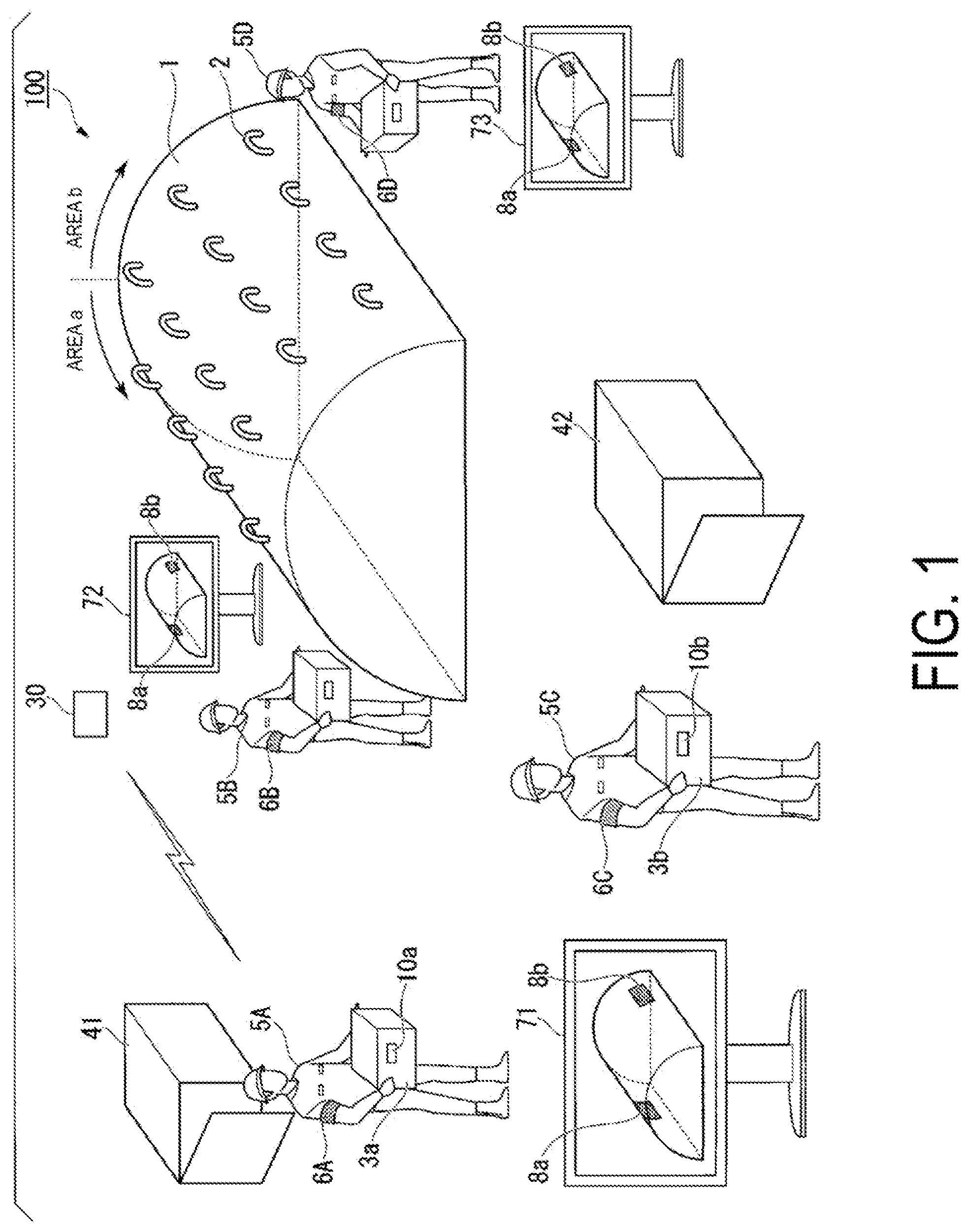
is a schematic view of a member attachment support system in the first embodiment of the present disclosure.
A member attachment support system 100 supports work in which workers 5 A to 5 D attach heat insulating blocks 3 a and other components to cover a surface of a high-temperature device (compressor, combustor, turbine, or the like) constituting a gas turbine. A casing 1 illustrated in is an example of the high-temperature device. In a case where there is no need for distinction between heat insulating blocks 3 a and 3 b , the heat insulating blocks 3 a and 3 b may simply be described as the heat insulating block 3 . Similarly, the workers 5 A to 5 D may be described as the workers 5 . Similarly, armbands 6 A to 6 D, attachment positions 8 a and 8 b , and radio frequency identifier (RFID) tags 10 a and 10 b may be described as armbands 6 , attachment positions 8 , and RFID tags 10 , respectively.
A plurality of tools 2 for fixing the heat insulating blocks 3 are provided on a surface of the casing 1 . As an example, the tools 2 are eye plates. The heat insulating block 3 is formed, for example, by filling a cubic bag with a laminate in which a heat insulating material and a metal plate are laminated. The bag is made of, for example, a glass cloth material made from woven glass fibers. On the surface of the heat insulating block 3 , the RFID tag 10 is sewn to the glass cloth material. Information (attachment position information) regarding the position at which the heat insulating block 3 is to be attached is recorded in the RFID tag 10 . A fixing tool (for example, a hook) (not illustrated) is provided on the surface of the heat insulating block 3 . The worker 5 attaches the heat insulating block 3 to the surface of the casing 1 by hanging the hook on the tool 2 . When the heat insulating blocks 3 are attached to all the tools 2 , the surface of the casing 1 is covered with the heat insulating blocks. An appropriate attachment position for the heat insulating block 3 is determined. For this reason, the worker 5 needs to attach each heat insulating block 3 to each tool 2 at an appropriate position. The member attachment support system 100 supports attachment work of the heat insulating blocks 3 by indicating to the worker 5 the position at which the heat insulating block 3 is to be attached.
Attachment Support Function
Next, a flow of the attachment work of the heat insulating blocks 3 by the workers 5 A to 5 D will be described.
The casing 1 is large and the range of attaching the heat insulating blocks 3 is wide. Thus, the surface of the casing 1 is divided into a plurality of work areas, and one or a plurality of the workers 5 are responsible for each work area. illustrates an example of division into two work areas (an area a and an area b). The workers 5 A and 5 B are responsible for the area a, and the workers 5 C and 5 D are responsible for the area b. The worker 5 A has the armband 6 A mounted on an arm. Similarly, the workers 5 B to 5 D have armbands 6 (armbands 6 B to 6 D, respectively) mounted on arms. The armbands 6 are distinguished using different colors depending on the work area that the workers are responsible for. For example, the armbands (armbands 6 A and 6 B) of the workers 5 A and 5 B are red. On the other hand, the armbands (armbands 6 C and 6 D, respectively) of the workers 5 C and 5 D are blue.
The heat insulating blocks 3 that are to be attached to the area a are stored in a storage 41 . The worker 5 A performs work of carrying the heat insulating block 3 out from the storage 41 . The worker 5 B performs work of attaching the heat insulating block 3 that was carried out by the worker 5 A to an appropriate position of the area a of the casing 1 . On the other hand, the heat insulating blocks 3 that are to be attached to the area b are stored in a storage 42 . The worker 5 C performs work of carrying the heat insulating block 3 out from the storage 42 . The worker 5 D receives the heat insulating block 3 carried out by the worker 5 C and performs work of attaching the heat insulating block 3 to an appropriate position of the area b.
An information processing terminal (not illustrated) (a terminal 20 in described below) is provided on the armband 6 . The terminal 20 is, for example, a mobile terminal, such as a smartphone, equipped with a display screen. The terminal 20 is fixed to the armband 6 such that the worker 5 can refer to the display screen. The display screen of the terminal 20 is equipped with an input function such as a touch panel. The terminal 20 has a function as an RFID reader. During the work of the worker 5 , the function of the RFID reader is activated. Hereinafter, an information processing terminal that the worker 5 A wears is referred to as a terminal 20 A, and terminals that the other workers 5 B to 5 D wear are referred to as terminals 20 B to 20 D. In a case where there is no need for distinction among the terminals 20 A to 20 D, the terminals 20 A to 20 D are described as the terminals 20 .
First, the worker 5 A carries the heat insulating block 3 a out from the storage 41 . In this case, the terminal 20 A and the RFID tag 10 a mounted on the heat insulating block 3 a approach, whereby the terminal 20 A performs communication with the RFID tag 10 a . The terminal 20 A acquires the attachment position information stored in the RFID tag 10 a and transmits the attachment position information to a server device 30 .
Similarly, the worker 5 C carries the heat insulating block 3 b out from the storage 42 . In this case, the terminal 20 C provided on the armband 6 C of the worker 5 C acquires the attachment position information from the RFID tag 10 b of the heat insulating block 3 b and transmits the attachment position information to the server device 30 .
The server device 30 generates a support image that displays the attachment positions of the heat insulating blocks 3 a and 3 b on the casing 1 and transmits the generated support image to monitors 71 to 73 and the terminals 20 A to 20 D. The monitors 71 to 73 display the support image. The terminals 20 display the support image on the display screens. For example, as illustrated in the monitor 71 , the attachment positions 8 a and 8 b are indicated in the support image along with the external shape of the casing 1 . The attachment position 8 a indicates the attachment position of the heat insulating block 3 a , and the attachment position 8 b indicates the attachment position of the heat insulating block 3 b . The attachment positions 8 a and 8 b are displayed in different colors to distinguish the attachment positions of the heat insulating blocks 3 a and 3 b . For example, the attachment position 8 a (area a) of the heat insulating block 3 a that the workers 5 A and 5 B are responsible for is displayed in red. The attachment position 8 b (area b) of the heat insulating block 3 b that the workers 5 C and 5 D are responsible for is displayed in blue. The workers 5 A and 5 B can recognize the attachment position of the heat insulating block 3 a by the display position of the attachment position 8 a having the same color as the color of the armbands of the workers 5 A and 5 B. Similarly, the workers 5 C and 5 D can recognize the attachment position of the heat insulating block 3 b by the display position of the attachment position 8 b being displayed in the same color as the color of the armbands of the workers 5 C and 5 D.
Next, the worker 5 A delivers the carried heat insulating block 3 a to the worker 5 B. The worker 5 B attaches the heat insulating block 3 a to the attachment position 8 a of the area a with reference to the support image displayed on the monitor 72 or the terminal 20 B. On the other hand, the worker 5 C delivers the carried heat insulating block 3 b to the worker 5 D. The worker 5 D attaches the heat insulating block 3 b to the attachment position 8 b of the area b with reference to the support image displayed on the monitor 73 or the terminal 20 D.
A division of labor system is established in which different workers 5 are responsible for the work of carrying the heat insulating blocks 3 out from the storages 41 and 42 and the work of attaching the heat insulating blocks 3 to the casing 1 , and this system can improve work efficiency. However, one worker 5 A may perform the work of detaching the heat insulating block 3 from the storage 41 and attaching the heat insulating block 3 to the area a. In regard to the area b, for example, the worker 5 C may perform the work of detaching the heat insulating block 3 from the storage 42 and attaching the heat insulating block 3 to the appropriate position of the area b.
With the member attachment support system 100 , the workers 5 A to 5 D can easily recognize the attachment positions of the heat insulating blocks 3 with reference to the support image displayed on the monitors 71 to 73 or the display screens of the terminals 20 provided on the armbands 6 of the workers 5 A to 5 D. With this, it is possible to reduce work time and improve work efficiency.
Progress Management Function
In a case where the heat insulating block 3 a is attached to the attachment position 8 a , the worker 5 B inputs attachment completion information to the terminal 20 B. The terminal 20 B transmits the attachment completion information of the heat insulating block 3 a to the server device 30 . The server device 30 stores that the attachment work of the heat insulating block 3 a is completed and that the worker 5 B performs the attachment work. The server device 30 generates a support image reflecting the completion of the attachment of the heat insulating block 3 a . The server device 30 transmits the generated support image to the monitors 71 to 73 and the terminals 20 A to 20 D. In the newly generated support image, for example, a portion of the attachment position 8 a is updated from red to gray indicating the completion of the work. As a result, the worker 5 can confirm the progress status of the attachment work. For example, the workers 5 C and 5 D who are responsible for the area b can confirm the progress of the work by the workers 5 A and 5 B. The server device 30 stores that the worker 5 B has performed the attachment work of the heat insulating block 3 a . A work history is aggregated for each worker 5 , making it possible to manage work results of the workers 5 .
Next, the configuration and function of the member attachment support system 100 will be described.
is a first block diagram illustrating an example of the member attachment support system in the first embodiment of the present disclosure.
The member attachment support system 100 includes the RFID tag 10 provided on the heat insulating block 3 , the terminal 20 provided on the armband 6 , and the server device 30 . The member attachment support system 100 may further include a plurality of RFID tags 10 and a plurality of terminals 20 .
The RFID tag 10 stores the attachment position information of the heat insulating block 3 on which the RFID tag 10 is mounted. The attachment position information is information including, for example, “No. 11 of the area a”. The area a is the work area (area information) illustrated in . No. 11 is identification information of a section of the attachment position of the heat insulating block 3 uniquely set in the area a. The RFID tag 10 is a passive tag. The RFID tag 10 is activated with power feed by the terminal 20 and communicates with the terminal 20 . The RFID tag 10 transmits the attachment position information including “No. 11 of the area a” or the like to the terminal 20 through this communication. The attachment position information includes area information and partition information. For example, in a case where the attachment position 8 a in is displayed in red, red indicates the “area a”, and a position where the attachment position 8 a is displayed indicates “No. 11”. That is, red corresponds to the area information, and the attachment position 8 a corresponds to the partition information.
The terminal 20 includes a reading unit 21 , a display control unit 22 , an input-output unit 23 , a control unit 24 , a storage unit 25 , and a communication unit 26 .
The reading unit 21 activates the RFID tag 10 with induced electromotive force and communicates with the RFID tag 10 through wireless communication, such as Near Field Communication (NFC). The reading unit 21 acquires the attachment position information stored in the RFID tag 10 through communication.
The display control unit 22 generates an image to be displayed on the display screen of the terminal 20 . For example, the display control unit 22 generates an image in which buttons used for managing the progress of the attachment work, such as “activate”, “complete”, and “release” are displayed.
The input-output unit 23 performs an input and an output with respect to the terminal 20 . For example, the input-output unit 23 includes a display screen, such as a liquid crystal display, on which the image generated by the display control unit 22 is displayed, and hardware buttons provided on the terminal 20 . The display screen is provided with a touch panel that detects contact of a finger, and the input-output unit 23 receives information input by the worker 5 through the touch panel.
The control unit 24 controls the operation of the terminal 20 based on an operation performed by the worker 5 through the input-output unit 23 . For example, in a case where the worker 5 depresses the “activate” button displayed on the display screen, the control unit 24 activates the reading unit 21 . In a case where the worker 5 depresses the “complete” button displayed on the display screen, completion of the attachment work of the heat insulating block 3 is transmitted to the server device 30 through the communication unit 26 .
The storage unit 25 stores various kinds of information.
The communication unit 26 communicates with the server device 30 or other terminals 20 over a wireless local area network (LAN) or the like.
Hereinafter, functional units provided in the terminal 20 A are described as a reading unit 21 A, a display control unit 22 A, an input-output unit 23 A, a control unit 24 A, a storage unit 25 A, and a communication unit 26 A. The same applies to the terminals 20 B to 20 D.
The server device 30 includes a management unit 31 , a display control unit 32 , a storage unit 33 , and a communication unit 34 .
The management unit 31 records the attachment position of the heat insulating block 3 , the attachment work of which is completed, in the storage unit 33 .
The display control unit 32 generates a support image to be displayed on the monitors 71 to 73 and the like.
The storage unit 33 stores an external shape image of the casing 1 , information of the attachment positions of the heat insulating blocks 3 on the surface of the casing 1 , and the like. For example, the storage unit 33 stores that “No. 11 of the area a” corresponds to the attachment position 8 a ( ) of the casing 1 .
The communication unit 34 communicates with the terminal 20 or the monitors 71 to 73 over a wireless local area network (LAN).
Next, a flow of processing of the member attachment support system 100 will be described in order of the operations of the workers 5 A and 5 B described referring to .
is a flowchart illustrating an example of the operation of the member attachment support system in the first embodiment of the present disclosure.
It is assumed that an application for use in the attachment work is activated in the terminal 20 . The application displays buttons on which, for example, text such as “activate”, “complete”, and “release”, is displayed, and the support image on the display screen of the terminal 20 .
First, the worker 5 A depresses the “activate” button on the display screen of the terminal 20 A. Then, the control unit 24 A activates the reading unit 21 A (RFID function) (Step S 11 ). The control unit 24 A notifies the server device 30 of the activation of the reading unit 21 A through the communication unit 26 A (Step S 12 ). The activation notification of the reading unit 21 A includes identification information of the terminal 20 A.
Similarly, the worker 5 B depresses the “activate” button on the display screen of the terminal 20 B. Then, the control unit 24 B activates the reading unit 21 B (RFID function) (Step S 13 ). The control unit 24 B notifies the server device 30 of the activation of the reading unit 21 B through the communication unit 26 B (Step S 14 ). The activation notification of the reading unit 21 B includes identification information of the terminal 20 B.
In the server device 30 , the management unit 31 receives the activation notification of the reading units 21 A and 21 B through the communication unit 34 . The management unit 31 records the identification information of the terminals 20 A and 20 B from which the activation of the RFID function is notified and a reception time of the activation notification (Step S 15 ). With this record, it is possible to manage the workers 5 who participate in the attachment work. A correspondence relationship of the terminal 20 A, the worker 5 A, and the work area (area a) and a correspondence relationship of the terminal 20 B, the worker 5 B, and the area a are registered in the storage unit 33 of the server device 30 . The storage unit 33 registers that the worker 5 A performs the work of carrying out the heat insulating block, and the worker 5 B performs the work of attaching the heat insulating block.
Next, the worker 5 A selects the heat insulating block 3 to be attached next in the storage 41 and carries out the selected heat insulating block 3 . In this case, the reading unit 21 A acquires the attachment position information from the RFID tag 10 of the selected heat insulating block 3 (Step S 16 ). The reading unit 21 A outputs the acquired attachment position information to the control unit 24 A. The control unit 24 A transmits the attachment position information to the server device 30 through the communication unit 26 A along with the identification information of the terminal 20 A (Step S 17 ). The attachment position information includes information regarding the work area (area information) and the partition information indicating the attachment position in the work area.
In the server device 30 , the display control unit 32 receives the notification of the attachment position information through the communication unit 34 . The display control unit 32 generates the support image in which the attachment position information (for example, the attachment position 8 a ) acquired from the terminal 20 A is displayed on the casing 1 (Step S 18 ). The display control unit 32 generates the support image in which the attachment position 8 a is displayed in red. The display control unit 32 transmits the support image to the monitors 71 to 73 or the terminals 20 A and 20 B through the communication unit 34 (Steps S 19 A and S 19 B).
The monitors 71 to 73 and the terminals 20 A and 20 B display the support image (Steps S 20 A and S 20 B). The workers 5 A and 5 B confirm the attachment position of the heat insulating block 3 with reference to the support image displayed on the monitors 71 to 73 and the display screens of the terminals 20 of the individual workers 5 A and 5 B.
In the server device 30 , the management unit 31 records the identification information of the terminal 20 A and the attachment position information in the storage unit 33 along with a reception time of the information. With this, it is possible to record a work history indicating that the worker 5 A has carried out the heat insulating block 3 .
Next, the worker 5 A delivers the carried heat insulating block 3 to the worker 5 B. The worker 5 B receives the heat insulating block 3 . In this case, the reading unit 21 B acquires the attachment position information from the RFID tag 10 of the received heat insulating block 3 (Step S 21 ). The reading unit 21 B outputs the acquired attachment position information to the control unit 24 B. The control unit 24 B transmits the attachment position information to the server device 30 through the communication unit 26 B (Step S 22 ).
In a case where the heat insulating block 3 is delivered, the worker 5 A inputs, to the terminal 20 A, information indicating that the heat insulating block 3 is released (is delivered to the worker 5 B) (Step S 23 ). For example, the worker 5 A depresses the “release” button on the display screen. Then, the control unit 24 A notifies the server device 30 of the release of the heat insulating block 3 along with the identification information of the terminal 20 A through the communication unit 26 A (Step S 24 ).
In the server device 30 , the management unit 31 records the identification information of the terminal 20 A and the release notification in the storage unit 33 along with a reception time of the information. The management unit 31 records the identification information of the terminal 20 B and the attachment position information in the storage unit 33 along with a reception time of the each information (Step S 25 ). With this, it is possible to record a work history indicating that the worker 5 A has delivered the heat insulating block 3 to the worker 5 B.
In a case where the worker 5 B confirms the attachment position of the heat insulating block 3 with reference to the monitor 72 or the display screen of the terminal 20 B, the worker 5 B attaches the heat insulating block 3 to the position indicated by the support image. When the attachment work is completed, the worker 5 B inputs, to the terminal 20 B, information indicating that the attachment of the heat insulating block 3 is completed (Step S 26 ). For example, the worker 5 B depresses the “complete” button on the display screen. The control unit 24 B notifies the server device 30 of the attachment completion of the heat insulating block 3 along with the identification information of the terminal 20 B through the communication unit 26 B (Step S 27 ).
In the server device 30 , the management unit 31 records the identification information of the terminal 20 B and the completion notification in the storage unit 33 along with a reception time of the each information (Step S 28 ). With this, it is possible to record a work history indicating the attachment completion of the heat insulating block 3 to the casing 1 by the worker 5 B. When the attachment of the heat insulating block 3 is completed, the display control unit 32 generates a support image after the attachment completion (Step S 29 ). The display control unit 32 generates a support image in which, for example, the attachment position of the heat insulating block 3 on the casing 1 is displayed in gray. The display control unit 32 transmits the support image to the monitors 71 to 73 and the terminals 20 A and 20 B through the communication unit 34 (Steps S 30 A and S 30 B).
The monitors 71 to 73 and the terminals 20 A and 20 B display the support image (Steps S 31 A and S 31 B). The workers 5 A and 5 B can confirm the position where the attachment work is performed, with reference to the support image displayed on the monitors 71 to 73 and the display screens of the terminals 20 of the individual workers 5 A and 5 B. A manager of the work can confirm the progress status of the attachment work.
In the flowchart of , the flow of the processing of the member attachment support system 100 based on the work performed by the workers 5 A and 5 B is described. However, in a case where the workers 5 C and 5 D perform the attachment work of the heat insulating block 3 to the area b in parallel with the above-described work, the member attachment support system 100 executes the same processing to display a support image in which an attachment status of the heat insulating blocks 3 in the areas a and b is displayed.
According to the present embodiment, even though the work of attaching the heat insulating block 3 is performed by a plurality of workers 5 , the attachment work can be performed while all workers 5 share the progress status of the work. For example, the workers 5 A and 5 B can proceed with the attachment work for the area a while confirming the work status of the other workers 5 C and 5 D.
Next, priority of the attachment work of the heat insulating block 3 will be described.
is a diagram illustrating an example of the attachment position of the heat insulating block in the first embodiment of the present disclosure.
is a cross-sectional view of the casing 1 illustrated in . Work efficiency is improved when the heat insulating blocks 3 are attached starting from the heat insulating block 3 to be attached to a lower position. Priority 1 to priority 5 are indicated in a descending order for the priority of the attachment work.
is a diagram illustrating an example of a storage for the heat insulating blocks in the first embodiment of the present disclosure.
illustrates a stored status of the heat insulating blocks 3 in the storage 41 . A shelf A to a shelf E are provided in the storage 41 . To attach the heat insulating blocks in the order of priority illustrated in , for example, the shelf A stores the heat insulating blocks 3 to be attached with the highest priority (priority 1 ). The heat insulating blocks 3 with the priority 2 are stored on the shelf B. Similarly, the shelf C stores the heat insulating blocks 3 with the priority 3 , and the shelves D and E store the heat insulating blocks 3 with the priority 4 and 5 , respectively. By storing the heat insulating blocks 3 in this manner, work efficiency can be improved.
For example, the worker 5 A first carries out the heat insulating blocks 3 on the shelf A one at a time and delivers the heat insulating blocks 3 to the worker 5 B. The worker 5 B attaches all the heat insulating blocks 3 with the priority 1 in the area a of . When the shelf A is completed, the worker 5 A then carries out the heat insulating blocks 3 on the shelf B and delivers the heat insulating blocks 3 to the worker 5 B. The worker 5 B attaches all the heat insulating blocks 3 with the priority 2 in the area a. The same applies to the priorities 3 to 5 . In this manner, the worker 5 B can attach the heat insulating blocks 3 in a descending order of the priority.
In a situation where the heat insulating blocks 3 are stored in the storage 41 , it is desirable to store the heat insulating blocks 3 on each shelf based on priority. For example, in a periodic inspection or the like, all the heat insulating blocks 3 are detached and stored in the storages 41 and 42 . After the end of the inspection work, the heat insulating blocks 3 are carried out from the storages 41 and 42 and are attached to the casing 1 again. In a situation where the heat insulating block 3 is detached, it is assumed that the worker 5 B performs the work of detaching the heat insulating block 3 from the casing 1 and delivers the detached heat insulating block 3 to the worker 5 A, and the worker 5 A stores the heat insulating block 3 in the storage 41 . Then, the worker 5 B detaches the heat insulating block 3 in order from the heat insulating block 3 associated with the priority 5 in , for example, and delivers the heat insulating block 3 to the worker 5 A. The worker 5 A stores the received heat insulating block 3 on the shelf E. Next, the worker 5 B detaches each heat insulating block 3 with the priority 4 , and the worker 5 A stores the heat insulating block 3 on the shelf D.
Hereinafter, similarly, the worker 5 A stores the heat insulating block with the priority 3 on the shelf C, stores the heat insulating block with the priority 2 on the shelf B, and stores the heat insulating block with the priority 1 on the shelf A.
By storing the heat insulating blocks 3 are stored in this manner, the workers can efficiently perform attachment work when attaching the heat insulating blocks 3 to the casing 1 again after the inspection work. The periodic inspection is performed periodically, for example, once per year. The heat insulating blocks 3 are determined to be stored on different shelves A to E depending on the priority of the attachment work. As a result, it is possible to improve the efficiency of the work of detaching and storing the heat insulating blocks 3 and the work of carrying out and attaching the heat insulating blocks 3 even in the case of repetitive inspection work or the like.
The order in which the heat insulating blocks 3 are attached may be any order. However, from the viewpoint of work efficiency, it is desirable to attach the heat insulating blocks in the order described referring to . With the storing method described referring to , when the worker 5 A carries out the heat insulating block 3 , it is possible to decrease the effort required to find the heat insulating block 3 to be carried out with priority. The worker 5 B can attach the heat insulating blocks 3 in an ideal order.
With the member attachment support system 100 , since the (durable) RFID tag 10 is mounted on the heat insulating block 3 , it is possible to display the support image for each inspection work to support the attachment work performed by the workers 5 . Even when the RFID tag 10 malfunctions or the like, the RFID tag 10 storing appropriate attachment position information is mounted again on the heat insulating block 3 , and thus it is possible to repeatedly use the member attachment support system 100 .
When the heat insulating block 3 cannot be stored in the form illustrated in , the worker 5 A can find and carry out the heat insulating block 3 with high priority using the member attachment support system 100 . For example, when the worker 5 A approaches the heat insulating block 3 , the attachment position of the heat insulating block 3 is displayed on the monitor 71 or the display screen of the terminal 20 A. When the priority illustrated in is known, the worker 5 A can confirm the priority of the heat insulating block 3 according to the attachment position of the heat insulating block 3 displayed in the support image. The worker 5 A can select the heat insulating block 3 with high priority and deliver the selected heat insulating block 3 to the worker 5 B.
Next, another configuration example of the member attachment support system according to the present embodiment will be illustrated.
is a second block diagram illustrating an example of the member attachment support system in the first embodiment of the present disclosure.
A member attachment support system 100 A does not include the server device 30 . Instead, the terminal 20 includes a management unit 27 , and an attachment completion time or an attachment position of the heat insulating block 3 is recorded in the storage unit 25 . The display control unit 22 generates a support image. For example, the terminal 20 A may be used as a master device, and other terminals 20 , such as the terminal 20 B, may be used a slave device. The slave device, such as the terminal 20 B, may perform notification of attachment position information acquired from the RFID tag 10 (Steps S 17 and S 22 in ), release notification (Step S 24 in ), or completion notification (Step S 27 in ) to the terminal 20 A, which is the master device, and the terminal 20 A may generate a support image (Steps S 18 and S 29 in ) or may record the progress (Steps S 25 and S 28 in ) and may transmit the support image to the slave devices or the monitors 71 to 73 . Alternatively, the respective terminals 20 may record the progress and may transmit results to be synchronized with one another, and the respective terminals 20 may generate the support image.
Even though the server device is not provided as described above, it is possible to realize the member attachment support system of the present embodiment.
In the above-described embodiment, although the monitors 71 to 73 are provided, the monitors 71 to 73 are not required. The processing in may be executed by displaying the support image on the display screen (input-output unit 23 ) of the terminal 20 . The support image may not be displayed on the display screen of the terminal 20 , and the support image may be displayed only on the monitors 71 to 73 . The terminal 20 may not include the display screen. The above-described functions may be realized by corresponding buttons (hardware) provided on the terminal 20 to “activate”, “release”, “complete” and the like described above.
In the above-described embodiment, the RFID tag 10 includes the attachment position information (area information and partition information). However, the identification information of the RFID tag 10 may be stored and the server device 30 may convert the identification information into the attachment position information.
Second Embodiment
Hereinafter, a member attachment support system according to a second embodiment of the present disclosure will be described referring to . In the first embodiment, an example where the worker 5 reads the attachment position information stored in the RFID tag 10 of the heat insulating block 3 using the terminal 20 provided on the armband 6 to confirm a specific location of the attachment position by using the monitor 71 or the like has been described. In the second embodiment, the terminal 20 is provided to be fixed in the vicinity of the monitor 71 , for example, and the worker 5 holds the heat insulating block 3 , moves to the location of the terminal 20 , and causes a reading device (reading unit 21 ), such as an RFID reader or a barcode reader connected to the terminal 20 , to read the attachment position information, and a result is displayed on the monitor 71 or the like.
is a schematic view illustrating the member attachment support system in the second embodiment of the present disclosure.
In the configuration of a member attachment support system 100 B according to the second embodiment of the present disclosure, the same components as the functional units constituting the member attachment support system 100 according to the first embodiment of the present disclosure are represented by the same reference signs, and description of these components will not be repeated. In the member attachment support system 100 B of the present embodiment, the terminals 20 are provided to be fixed at predetermined positions and not on the armbands 6 of the workers 5 A to 5 D. For example, terminals 20 a , 20 b , and 20 c are provided near the monitors 71 , 72 , and 73 , respectively. The terminals 20 a to 20 c may be mobile terminals, such as smartphones, as in the first embodiment or may be configured of stationary computers, such as personal computers (PCs). Although the functional units provided in the terminals 20 a to 20 c are the same as those described referring to RFID readers or barcode readers, for example, may be connected to the terminals 20 a to 20 c to constitute reading units 21 a to 21 c . Keyboards and mouses (not illustrated) and the monitors 71 to 73 may be connected to the terminals 20 a to 20 c and may constitute input-output units 23 a to 23 c . For example, a display control unit 22 a of the terminal 20 a displays an image on the monitor 71 .
Attachment Support Function
The operation of the member attachment support system 100 B will be described. For example, the worker 5 A carries the heat insulating block 3 a out from the storage 41 . The worker 5 B receives the heat insulating block 3 a from the worker 5 A. The worker 5 B carries the heat insulating block 3 a near the monitor 72 , and causes the RFID reader (not illustrated) connected to the terminal 20 b to read the attachment position information stored in the RFID tag 10 a . The terminal 20 b acquires the attachment position information from the RFID tag 10 a and transmits the attachment position information to the server device 30 .
Similarly, the worker 5 C carries the heat insulating block 3 b out from the storage 42 . The worker 5 D receives the heat insulating block 3 b from the worker 5 C and approaches the RFID reader (reading unit 21 c ) (not illustrated) connected to the terminal 20 c near the monitor 73 . Then, the terminal 20 c acquires the attachment position information stored in the RFID tag 10 b read by the RFID reader and transmits the information to the server device 30 .
Subsequent processing is the same as in the first embodiment. For example, the server device 30 generates a support image in which the attachment positions of the heat insulating blocks 3 a and 3 b on the casing 1 are displayed and transmits the generated support image to the terminals 20 a to 20 c and the monitors 71 to 73 . The terminals 20 a , 20 b , and 20 c display the support image on the display screens of the respective terminals 20 a , 20 b , and 20 c . The monitors 71 , 72 , and 73 display the support image. The worker 5 B confirms the attachment position displayed on the monitor 72 and attaches the heat insulating block 3 a to the attachment position 8 a of the area a. The worker 5 D confirms the attachment position displayed on the monitor 73 and attaches the heat insulating block 3 b to the attachment position 8 b of the area b.
Next, when the workers 5 B and 5 D attach the heat insulating blocks 3 , information indicating that the attachment of the heat insulating blocks 3 a and 3 b is completed is input to the terminals 20 a and 20 b . Then, the terminals 20 a and 20 b notify the server device 30 of the attachment completion of the heat insulating blocks 3 a and 3 b along with the identification information of the respective terminals through the same processing as in the first embodiment. The server device 30 records the progress of the work and generates a support image reflecting the work status. The terminals 20 a to 20 c and the monitors 71 to 73 receive the support image reflecting the work status from the server device 30 and display the support image.
With the member attachment support system 100 B of the present embodiment, the workers 5 A to 5 D can easily recognize the attachment positions of the heat insulating blocks 3 without wearing the armbands 6 . With this, it is possible to obtain the same effects as in the first embodiment, such as a reduction in time of the attachment work of the heat insulating blocks 3 and improvement of work efficiency, with a simpler system configuration than in the first embodiment.
Third Embodiment
Hereinafter, a member attachment support system according to a third embodiment of the present disclosure will be described referring to to 15 . In the configuration according to the third embodiment of the present disclosure, the same components as those of the member attachment support systems 100 to 100 B according to the first embodiment and the second embodiment of the present disclosure are represented by the same reference signs, and description of the components will not be repeated. As described above, the member attachment support systems 100 to 100 B provide the function of guiding the attachment position of the heat insulating blocks 3 . In contrast, a member attachment support system 100 C according to the third embodiment not only displays the attachment position of the heat insulating blocks 3 , but also provides a function of storing and displaying the storage location of each detached heat insulating block 3 . For example, during a periodic inspection, work of detaching the heat insulating blocks 3 from the casing 1 and attaching the heat insulating blocks 3 again after inspection is performed. With the function of displaying the storage location of the heat insulating block 3 , it is possible to reduce effort of finding the heat insulating block 3 when the heat insulating block 3 is to be reattached to the casing 1 after inspection.
is a block diagram illustrating an example of the member attachment support system in the third embodiment of the present disclosure.
The member attachment support system 100 C includes RFID tags 10 provided on the heat insulating blocks 3 , terminals 20 , terminals 50 , and a server device 30 C.
The RFID tags 10 and the terminals 20 are the same as those in the first embodiment and the second embodiment, and thus description of the RFID tags 10 and the terminals 20 will not be repeated.
The server device 30 C includes the management unit 31 , the display control unit 32 , the storage unit 33 , the communication unit 34 , and a storage location recording unit 35 .
The storage location recording unit 35 records a location where the worker 5 stores the heat insulating block 3 for each heat insulating block 3 .
The terminal 50 includes a reading unit 51 , a display control unit 52 , an input-output unit 53 , a control unit 54 , a storage unit 55 , and a communication unit 56 . The terminal 50 is constituted of a mobile terminal, such as a smartphone, or a stationary computer, such as a PC.
The reading unit 51 communicates with the RFID tag 10 through wireless communication, such as Near Field Communication (NFC). The reading unit 51 acquires attachment position information stored in the RFID tag 10 through communication. The reading unit 51 may be an RFID reader or a barcode reader connected to the terminal 50 .
The display control unit 52 generates an image to be displayed on the display screen of the terminal 50 . For example, the display control unit 52 generates an image in which buttons used for storing and carrying out the heat insulating block, such as “activate”, “start to store”, “next” and the like, are displayed.
The input-output unit 53 performs an input and an output with respect to the terminal 50 . For example, the input-output unit 53 includes a display screen provided in the terminal 50 , hardware buttons provided on the terminal 50 , a touch panel provided on the display screen, a monitor connected to the terminal 50 , and a keyboard.
The control unit 54 controls the operation of the terminal 50 based on an operation performed by the worker 5 through the input-output unit 53 . For example, in a case where the worker 5 depresses the “activate” button displayed on the display screen, the control unit 54 activates the reading unit 51 . In a case where the worker 5 depresses the “start to store” button displayed on the display screen, the start of storage work of the heat insulating block 3 is transmitted to the server device 30 C through the communication unit 56 .
The storage unit 55 stores various kinds of information.
The communication unit 56 communicates with the server device 30 C over a wireless local area network (LAN) or the like.
Hereinafter, functional units provided in a terminal 50 A are described as a reading unit 51 A, a display control unit 52 A, an input-output unit 53 A, a control unit 54 A, a storage unit 55 A, and a communication unit 56 A. The same applies to a terminal 50 C.
is a first schematic view of the member attachment support system in the third embodiment of the present disclosure.
illustrates the member attachment support system 100 C of the present embodiment. Unlike the configuration of , the terminal 50 A is provided on the armband 6 A worn by the worker 5 A, and the terminal 20 B is provided on the armband 6 B worn by the worker 5 B. The terminal 50 C is provided on the armband 6 C worn by the worker 5 C, and the terminal 20 D is provided on the armband 6 D worn by the worker 5 D.
Recording of Storage Place
First, a situation where the heat insulating block 3 is detached will be described. For example, at the time of the start of a periodic inspection, the worker 5 B detaches the heat insulating block 3 a from the area a of the casing 1 . The worker 5 A receives the heat insulating block 3 a from the worker 5 B and stores the heat insulating block 3 a in the storage 41 . Similarly, the worker 5 D detaches the heat insulating block 3 b from the area b, and the worker 5 C stores the heat insulating block 3 b in the storage 42 .
is a flowchart illustrating an example of the operation of the member attachment support system at the time of storing the heat insulating block according to the third embodiment of the present disclosure.
is a diagram illustrating recording processing of the storage location of the heat insulating block according to the third embodiment of the present disclosure.
First, for example, the worker 5 A depresses the “start to store” button displayed on the display screen of the terminal 50 A to input information indicating the start of the storage work of the heat insulating block 3 to the terminal 50 A. In the terminal 50 A, the input-output unit 53 A receives the input. The communication unit 56 A notifies the server device 30 C of the start of the storage work and the identification information of the terminal 50 A (Step S 41 ). In the server device 30 C, the communication unit 34 receives the notification. The display control unit 32 generates a storage location image (Step S 42 ). ( a ) illustrates an example of a storage location image. ( a ) is, for example, a plan view of the storage 41 and illustrates a state in which a floor of the storage 41 is divided into regions of a predetermined size and identification numbers, such as “P 1 ” and “P 2 ”, are attached to the respective regions.
“P 1 ” or the like is a location where one heat insulating block 3 is stored. The display control unit 32 generates the storage location image illustrated in ( a ) , and the communication unit 34 transmits the storage location image to the terminal 50 A (Step S 43 ). In the terminal 50 A, the communication unit 56 A receives the storage location image, and the display control unit 52 A displays the storage location image on the display screen of the terminal 50 A (Step S 44 ).
Furthermore, the worker 5 A depresses the “activate” button on the display screen of the terminal 50 A. Then, the control unit 54 A activates the reading unit 51 A (RFID function) (Step S 45 ).
On the other hand, the worker 5 B detaches the heat insulating block 3 a from the casing 1 and delivers the heat insulating block 3 a to the worker 5 A. In this case, the reading unit 51 A acquires the attachment position information from the RFID tag 10 of the received heat insulating block 3 a (Step S 46 ). In a situation where the heat insulating block 3 a is stored, the attachment position information functions as identification information of the heat insulating block 3 . The reading unit 51 A outputs the acquired attachment position information to the control unit 54 A.
The worker 5 A carries the received heat insulating block 3 a to the storage 41 and places (stores) the heat insulation block 3 a any place in the storage. The worker 5 A selects a storage location (“P 1 ”, “P 2 ”, or the like) corresponding to the position where the heat insulating block 3 a is placed, in the storage location image displayed on the terminal 50 A, and inputs the storage location of the heat insulating block 3 a (Step S 47 ). The input-output unit 53 A receives this input and outputs information regarding the selected storage location to the control unit 54 A. The control unit 54 A transmits the attachment position information and information (such as “P 1 ”) regarding the storage location to the server device 30 C along with the identification information of the terminal 50 A through the communication unit 56 A (Step S 48 ).
In the server device 30 C, the storage location recording unit 35 acquires the above-described information through the communication unit 34 . The storage location recording unit 35 records the attachment position information (the identification information of the heat insulating block 3 ) and information regarding the storage location in the storage unit 33 in correspondence with each other (Step S 49 ). ( b ) illustrates an example of a table in which information regarding the storage location is recorded. As illustrated in ( b ) , the table stored in the storage unit 33 stores the attachment position information, the storage location information, and an attachment order in correspondence with one another. The attachment order is determined in advance for each piece of attachment position information. For example, as described referring to , it is known that work efficiency is improved in a case where the heat insulating blocks 3 are attached in such an order depending on the attachment positions. In the table of ( b ) , for example, based on an order in which work efficiency is improved, numbers 1, 2, 3, . . . indicating the attachment order correspond to the heat insulating blocks 3 from the heat insulating block 3 to be attached first. In a case where the attachment position information and information regarding the storage location are transmitted from the terminal 50 A, the storage location recording unit 35 stores the received information regarding the storage location in a “storage location information” field of a record having a value corresponding to the received attachment position information in an “attachment position information” field.
Next, the display control unit 32 updates the storage location image (Step S 50 ). For example, in a case where “P 1 ” is received as information regarding the storage location, the display control unit 32 generates a storage location image in which the position of “P 1 ” is grayed out. The communication unit 34 transmits the updated storage location image to the terminal 50 A (Step S 51 ). In the terminal 50 A, the communication unit 56 A receives the updated storage location image, and the display control unit 52 A displays the updated storage location image (Step S 52 ). With this display, the worker 5 A can confirm that the storage location of the heat insulating block 3 placed by the worker 5 A is recorded.
The workers 5 A and 5 B repeat the same work until all heat insulating blocks 3 in the area a are detached and stored. Similarly, in regard to the area b, the work in which the worker 5 D detaches the heat insulating block 3 b and the worker 5 C inputs the storage location of the heat insulating block 3 b to the terminal 50 C while storing the heat insulating block 3 b in the storage 42 is repeated. The terminal 50 C transmits the attachment position information and information regarding the storage location of the heat insulating block 3 b to the server device 30 C every time. In this manner, in a case where all heat insulating blocks 3 are detached from the casing 1 and stored, information regarding the storage locations of all heat insulating blocks 3 is recorded in the server device 30 C.
Display of Storage Location
Next, the work of attaching the heat insulating blocks 3 to the casing 1 after inspection will be described. The worker 5 A carries the heat insulating block 3 out from the storage 41 in a work order determined in advance and delivers the heat insulating block 3 to the worker 5 B. The worker 5 B attaches the received heat insulating block 3 to an appropriate attachment position of the area a. Similarly, the worker 5 C carries the heat insulating block 3 out from the storage 42 , and the worker 5 D receives the heat insulating block 3 and attaches the heat insulating block 3 to an appropriate attachment position of the area b. The support for the attachment work performed by the workers 5 B and 5 D is the same as in the first embodiment.
is a flowchart illustrating an example of the operation of the member attachment support system at the time of carrying out the heat insulating block according to the third embodiment of the present disclosure.
First, for example, the worker 5 A depresses a “start to attach” button displayed on the display screen of the terminal 50 A to input information indicating the start of the attachment work of the heat insulating block 3 a to the terminal 50 A. In the terminal 50 A, the input-output unit 53 A receives the input. The communication unit 56 A notifies the server device 30 C of the start of the attachment work and the identification information of the terminal 50 A (Step S 61 ). In the server device 30 C, the communication unit 34 receives the notification. Then, the display control unit 32 generates a storage location image indicating the storage location of the heat insulating block 3 to be first attached (Step S 62 ). Specifically, the display control unit 32 refers to data of the attachment order “1” from the table illustrated in ( b ) and reads out the attachment position information and the storage location information. For example, in a case where the heat insulating block 3 to be attached first is stored in “P 8 ,” the display control unit 32 generates an image in which only “P 8 ” is displayed in a different form from other regions (“P 1 ” and the like) in the storage location image illustrated in ( a ) . For example, the display control unit 32 generates an image in which characters or a background of P 8 is displayed in a different color from other regions or flashes to be highlighted. The communication unit 34 transmits the storage location image and the attachment position information (the identification information) of the heat insulating block 3 to be attached first to the terminal 50 A (Step S 63 ). In the terminal 50 A, the communication unit 56 A receives the storage location image, and the display control unit 52 A displays the storage location image on the display screen of the terminal 50 A (Step S 64 ). The worker 5 A carries the heat insulating block 3 a out from a location corresponding to “P 8 ” in the storage 41 with reference to the display of the storage place image and delivers the heat insulating block 3 a to the worker 5 B.
When the worker 5 A carries the heat insulating block 3 a out from the location corresponding to “P 8 ”, the reading unit 51 A of the terminal 50 A may be configured to read out the attachment position information from the RFID tag 10 of the heat insulating block 3 a , collate the attachment position information with the attachment position information acquired from the server device 30 C, and in a case where information is not coincident, display an error message.
As in the first embodiment, the worker 5 B that receives the heat insulating block 3 a reads the attachment position information of the heat insulating block 3 a using the terminal 20 B and causes the attachment position to be displayed on the display screen of the terminal 20 B, the monitor 72 , or the like. The worker 5 B attaches the heat insulating block 3 while referring to the attachment position displayed on the monitor 72 or the like.
On the other hand, in a case where the heat insulating block 3 a to be attached first is delivered to the worker 5 B, for example, the worker 5 A depresses the “next” button displayed on the display screen of the terminal 50 A to input information requesting the storage location of the heat insulating block 3 to be next attached to the terminal 50 A. The input-output unit 53 A receives this input, and the communication unit 56 A notifies the server device 30 C of the information requesting the storage location of the next heat insulating block 3 and the identification information of the terminal 50 A (Step S 65 ). In the server device 30 C, the communication unit 34 receives this notification, and the display control unit 32 generates a storage location image indicating the storage location of the heat insulating block 3 to be next attached (Step S 66 ). Specifically, the display control unit 32 specifies a record of the attachment order “2” with reference to the table of ( b ) and reads out the attachment position information and the storage location information. Then, the display control unit 32 generates a storage location image in which the next storage location is highlighted. The communication unit 34 transmits the storage location image and the attachment position information of the heat insulating block to be next attached to the terminal 50 A (Step S 67 ). In the terminal 50 A, the communication unit 56 A receives the storage location image, and the display control unit 52 A displays the storage location image on the display screen (Step S 68 ). The worker 5 A carries out the heat insulating block 3 to be next attached with reference to the display of the storage location image and delivers the heat insulating block 3 to the worker 5 B.
In this manner, the workers 5 A and 5 B repeat the same work until all heat insulating blocks 3 a in the area a are attached. Similarly, in regard to the area b, the server device 30 C notifies the terminal 50 C, which is worn by the worker 5 C, of the storage location of the heat insulating block 3 b in the attachment order, and the worker 5 C carries the heat insulating block 3 b out from the storage 42 in compliance with the guide. The worker 5 D repeats the work of receiving the heat insulating block 3 from the worker 5 C and attaching the heat insulating block 3 to the area b by using the terminal 20 D.
According to the present embodiment, since the worker 5 can confirm the storage location of the heat insulating block 3 to be next attached, the worker 5 can find the heat insulating block 3 to be next attached without hesitation. With this configuration, it is possible to improve the efficiency of the attachment work of the heat insulating blocks 3 . The worker 5 can store the heat insulating blocks 3 detached from the casing 1 at any location without arranging the heat insulating blocks 3 in the attachment order as illustrated in .
In the above description, although the workers 5 A and 5 C who store or carry out the heat insulating block 3 and the workers 5 B and 5 D who detach and attach the heat insulating block 3 cooperate to perform work, one worker 5 may perform a series of works of detaching, storing, carrying out, and attaching the heat insulating block 3 . In such a case, for example, the functions in the terminal 50 may be implemented in the terminal 20 , and the worker 5 may wear the armband 6 on which the terminal 20 is provided.
In the above description, although the storage location of the heat insulating block 3 is input to the terminal 50 each time the heat insulating block 3 is stored, that is, storage and reading and the input of the storage location are performed as a set, the present disclosure is not limited to the configuration. For example, the reading and input of the storage location may be performed collectively after all heat insulating blocks 3 are stored. Specifically, a specific worker 5 (for example, the worker 5 A) may read the attachment position information one by one using the terminal 50 A and may record the storage location one by one for all heat insulating blocks 3 placed in the storages 41 and 42 . With this, the worker 5 who performs the storage work of the heat insulating block 3 may not perform the work of recording the storage location.
In the configuration example of , although the terminal 20 and the terminal 50 are provided on the armband 6 of the worker 5 , the third embodiment can be combined with the second embodiment.
is a second schematic view of the member attachment support system in the third embodiment of the present disclosure. In a member attachment support system 100 C 1 illustrated in , unlike the configuration of , the terminal 50 A is provided on the armband 6 A worn by the worker 5 A, and the worker 5 B does not wear an armband 6 . The terminal 50 C is provided on the armband 6 C worn by the worker 5 C, and the worker 5 D does not wear an armband 6 . In such a configuration, the worker 5 A stores and carries out the heat insulating block 3 a while operating the terminal 50 A. The worker 5 B carries the heat insulating block 3 a received from the worker 5 A, for example, to the terminal 20 b , causes the reading unit 21 b to read the RFID tag 10 , and attaches the heat insulating block 3 a to the appropriate position on the casing 1 with reference to the attachment position displayed on the monitor 72 . The same applies to the workers 5 C and 5 D.
For example, there is an experienced worker who, after confirming the attachment position with reference to the monitors 72 and 73 , can then attach the heating insulating block to a correct position later. According to the configuration illustrated in , the workers 5 B and 5 D can perform the attachment work with light equipment without wearing the armband 6 . It is possible to suppress the cost of the member attachment support system 100 C 1 .
In contrast to the configuration example of , a configuration in which the terminal 50 is stationary is also possible.
is a third schematic view of the member attachment support system in the third embodiment of the present disclosure. In a member attachment support system 100 C 2 illustrated in , unlike the configuration of , the worker 5 A does not wear an armband 6 , and the worker 5 B wears the armband 6 B on which the terminal 20 B is provided. The worker 5 C does not wear an armband 6 , and the worker 5 D wears the armband 6 D on which the terminal 20 C is provided. The terminal 50 is provided to be fixed near the monitor 71 , and the workers 5 A and 5 C hold the heat insulating blocks 3 , move to a position where the terminal 50 is provided, and cause the RFID reader or the like (reading unit 51 ) connected to the terminal 50 to read the attachment position information. In addition, the storage location image of the storage 41 and the storage location image of the storage 42 are switched, and the workers 5 A and 5 C input planned storage locations of the heat insulating blocks 3 instantaneously. Then, the workers 5 A and 5 C store the heat insulating blocks 3 at the planned storage locations of the storages 41 and 42 input by the individual workers 5 A and 5 C. Alternatively, the workers 5 A and 5 C may store the heat insulating blocks 3 after the RFID reader reads the attachment position information and may input actual storage locations to the terminal 50 after storage. In a situation where the heat insulating block is to be attached, the worker 5 A carries out the heat insulating block 3 a while confirming the storage location displayed on the monitor 71 . The worker 5 B causes the terminal 20 B to read the RFID tag 10 for the heat insulating block 3 a received from the worker 5 A. The worker 5 B attaches the heat insulating block 3 a to the appropriate position on the casing 1 with reference to the attachment position displayed on the display screen of the terminal 20 B. The same applies to the workers 5 C and 5 D. Next, as illustrated in , the terminal 50 and the monitor may be provided for each of the storage 41 and the storage 42 .
According to the configuration illustrated in , for example, in which a plurality of workers 5 cooperatively store the heat insulating blocks 3 in the storage 41 , the workers can refer to the storage location image of the monitor 71 and can work while discussing where to store the next heat insulating block 3 .
Note that both the terminal 20 and the terminal 50 may be stationary.
is a fourth schematic view of the member attachment support system in the third embodiment of the present disclosure. In a member attachment support system 100 C 3 illustrated in , the workers 5 A to 5 D do not wear the armbands 6 , terminals 50 a and 50 b are provided to be fixed near monitors 71 a and 71 b , and the terminals 20 b and 20 c are provided to be fixed near the monitors 72 and 73 .
The worker 5 A holds the heat insulating block 3 a , moves to a position where the terminal 50 a is provided, and causes the attachment position information to be read to perform the storage work. Furthermore, the worker 5 A carries out the heat insulating block 3 a in the attachment order based on the display of the monitor 71 a . Then, the worker 5 B receives the heat insulating block 3 a carried out by the worker 5 A, moves to a position where the terminal 20 b is provided, causes the attachment position information to be read, and causes the attachment position of the heat insulating block 3 a to be displayed on the monitor 72 .
Similarly, the worker 5 C stores and carries out the heat insulating block 3 b using the terminal 50 b and the monitor 71 b . The worker 5 D performs the attachment work using the terminal 20 c and the monitor 73 .
According to the configuration illustrated in , it is possible to introduce and operate the system simply and at low cost compared to the configurations illustrated in , 13 , and 14 .
Although a configuration in which the server device 30 is not provided is described in the first embodiment ( ), in the third embodiment, the terminal 20 may have the configuration illustrated in , the storage location recording unit 35 of the server device 30 C, the function of generating the storage location image of the display control unit 32 , and the table of the storage unit 33 may be implemented by the terminal 50 , and the server device 30 C may not be provided.
In the third embodiment, both the functions of the terminal 20 and the functions of the terminal 50 may be implemented by one terminal device, and the terminal device may be provided on the armband 6 or may be provided near the monitor 71 .
In the first to third embodiments described above, although the RFID tag 10 in which the attachment position information is stored is attached to the heat insulating block 3 , a label or the like displaying code information (barcode, QR code (Registered Trademark), or the like) indicating the attachment position information may be applied to the surface of the heat insulating block 3 instead of the RFID tag 10 . In this case, an application for reading the code information is installed on the terminal 20 and the terminal 50 , or a code reading device (barcode reader or the like) is attached to the terminal 20 and the terminal 50 to reach the attachment position information.
In the above description of the first to third embodiments, although an example is given where the worker wears the armband 6 on which the terminal 20 or the terminal 50 is provided, the support image output from the terminal 20 or the storage location image output from the terminal 50 may be displayed on an eyeglass type display. Alternatively, the functions of the terminal 20 or the terminal 50 may be implemented by an eyeglass type wearable terminal. In a case where an augmented reality technique is applied, for example, in the case of a support image, the attachment position of the heat insulating block 3 may be displayed on the actual casing 1 in a superimposed manner. With the use of the eyeglass type display or the like, work efficiency can be improved because both hands can be freely used.
In the above-described embodiments, the attachment position of the heat insulating block 3 is displayed by the display of the support image, and the storage location of the heat insulating block 3 to be next attached is displayed by the storage location image, but the attachment position and the storage location may be guided by sound. For example, in the configuration of , a speaker connected to (or incorporated in) the terminal 50 A of the armband 6 A guides the storage location by sound, and the worker 5 A carries the heat insulating block 3 a out from the guided place and delivers the heat insulating block 3 a to the worker 5 B. The worker 5 B causes the attachment position information stored in the RFID tag 10 a to be read using the RFID reader connected to the terminal 20 B of the armband 6 B. Then, the speaker incorporated in (or connected to) the terminal 20 B guides the attachment position (area information and partition information) of the heat insulating block 3 a by sound. With the sound guide, the worker 5 A can carry out the heat insulating block 3 a without referring to the monitor 71 or the like. The worker 5 B can perform the attachment work of the heat insulating block 3 a without referring to the monitor 72 or the like.
The terminal 20 , the server device 30 , and the terminal 50 are implemented in a computer including, for example, a processor, such as a central processing unit (CPU), a main storage device, an auxiliary storage device, an input/output interface, and a communication interface. In this configuration, the operations of the respective functional units described above are stored in the auxiliary storage device in a format of a program. The CPU reads the program from the auxiliary storage device, deploys the program to the main storage device, and executes the above-described processing in compliance with the program. The CPU secures a storage area in the main storage device in compliance with the program. The CPU secures a storage area for storing data during processing in the auxiliary storage device in compliance with the program.
In addition, the constituent elements in the embodiments as described above can be replaced as appropriate with commonly known constituent elements, to the extent that it does not depart from the intention of the present disclosure. Also, the technical scope of the present disclosure is not limited to the embodiments described above, and various modifications may be further made without departing from the spirit of the present disclosure.
For example, a device to which the member attachment support system of the present embodiment is applied is not limited to a high-temperature device constituting a gas turbine. The RFID tag 10 or the label on which the code information is displayed is an example of an identification information storage unit. The terminal 20 and the terminal 50 to which the RFID reader or the barcode reader is connected are examples of a terminal device. The monitors 71 to 73 and the display screen of the terminal 20 are examples of a display device. The storage unit 33 that stores the table illustrated in ( b ) is an example of a storage location storage unit. A speaker connected to or embedded in the terminal 20 or a speaker connected to or embedded in the terminal 50 is an example of a sound output device.
In the above-described embodiments, although the attachment position information includes the area information and the partition information, since the workers 5 A and 5 C need not know the partition information, only the area information may be transmitted from the RFID tag 10 a and 10 b to the terminals 20 A and 20 C carried by the workers 5 A and 5 C. Then, only the area information may be displayed on the monitor 71 and the display devices of the terminal 20 A and 20 C that are referred to by the workers 5 A and 5 C. Only the partition information may be transmitted from the RFID tags 10 a and 10 b to the terminals 20 B and 20 D carried by the workers 5 B and 5 D. Then, only the partition information may be displayed on the monitors 72 and 73 and the display devices of the terminals 20 B and 20 D that are referred to by the workers 5 B and 5 D. Alternatively, the area information and the partition information may be transmitted from the RFID tags 10 a and 10 b to the terminals 20 B and 20 D carried by the workers 5 B and 5 D.
INDUSTRIAL APPLICABILITY
With the member attachment support system and the member attachment support method described above, it is possible to improve the efficiency of work of attaching a heat insulating member to a device.
REFERENCE SIGNS LIST
•
• 1 Casing • 2 Tool • 3 , 3 a , 3 b Heat insulating block • 5 , 5 A, 5 B, 5 C, 5 D Worker • 6 , 6 A, 6 B, 6 C, 6 D Armband • 8 , 8 a , 8 b Attachment position • 10 , 10 a , 10 b RFID tag • 20 , 20 A, 20 B, 20 a , 20 b , 20 c Terminal • 21 , 21 A, 21 B Reading unit • 22 , 22 A, 22 B Display control unit • 23 , 23 A, 23 B Input-output unit • 24 , 24 A, 24 B Control unit • 25 , 25 A, 25 B Storage unit • 26 , 26 A, 26 B Communication unit • 27 A, 27 B Management unit • 30 Server device • 31 Management unit • 32 Display control unit • 33 Storage unit • 34 Communication unit • 41 , 42 Storage • 50 , 50 A, 50 B Terminal • 51 , 51 A Reading unit • 52 , 52 A Display control unit • 53 , 53 A Input-output unit • 54 , 54 A Control unit • 55 , 55 A Storage unit • 56 , 56 A Communication unit • 71 , 72 , 73 Monitor • 100 , 100 A Member attachment support system
Figures (15)
Citations
This patent cites (21)
- US5453933
- US8326707
- US8938886
- US2007/0229268
- US2008/0125950
- US2012/0290591
- US2013/0293355
- US2014/0236450
- US2016/0358324
- US2019/0304150
- US107423650
- US1 923 823
- US5-278806
- US2000-24849
- US2005-222165
- US2007-87249
- US2008-1481
- US2009-037416
- US2016-221671
- US475911
- US2015/063884