Display Device, a Vehicle with a Display Device and Display Virtual Image Method
Abstract
A display apparatus ( 500 ) for displaying a virtual image (VIMG 1 ) comprises: an optical engine (ENG 1 ) to form input light (IN 1 ), which represents an input image (IMG 0 ), an expander device (EPE 1 ) to form light beams (B 3 P0,R ,B 3 P1,R ) of output light (OUT 1 ) by expanding light beams (B 0 P0,R ,B 0 P1,R ) of the input light (IN 1 ), the expander device (EPE 1 ) comprising: a waveguide plate (SUB 1 ), a diffractive in-coupling element (DOE 1 ) to form first guided light (B 1 a ) and second guided light (B 1 b ) by coupling input light (IN 1 ) into the waveguide plate (SUB 1 ), wherein the display apparatus ( 500 ) comprises a base (BASE 1 ) and an actuating mechanism (MOTOR 1 ) to cause rotary motion of the expander device ( 500 ) with respect to the base (BASE 1 ), wherein an angle (γ 1 ) between an optical axis (AX 0 ) of the optical engine (ENG 1 ) and the axis (AX 1 ) of rotation of the expander device ( 500 ) is in the range of 10° to 45°.
Claims (7)
1. A display apparatus ( 500 ) for displaying a virtual image (VIMG 1 ), the display apparatus ( 500 ) comprising: an optical engine (ENG 1 ) to form input light (IN 1 ), which represents an input image (IMG 0 ), an expander device (EPE 1 ) to form light beams (B 3 P0,R ,B 3 P1,R ) of output light (OUT 1 ) by expanding light beams (B 0 P0,R ,B 0 P1,R ) of the input light (IN 1 ), the expander device (EPE 1 ) comprising: a waveguide plate (SUB 1 ), a diffractive in-coupling element (DOE 1 ) to form first guided light (B 1 a ) and second guided light (B 1 b ) by coupling the input light (IN 1 ) into the waveguide plate (SUB 1 ), a first out-coupling element (DOE 3 a ) to form output light (OUT 1 ) by coupling the first guided light (B 1 a ) out of the waveguide plate (SUB 1 ), and a second out-coupling element (DOE 3 b ) to form output light (OUT 1 ) by coupling the second guided light (B 1 b ) out of the waveguide plate (SUB 1 ), wherein the display apparatus ( 500 ) comprises a base (BASE 1 ) and an actuating mechanism (MOTOR 1 ) to cause rotary motion of the expander device (EPE 1 ) with respect to the base (BASE 1 ), wherein an angle (γ 1 ) between an optical axis (AX 0 ) of the optical engine (ENG 1 ) and the axis (AX 1 ) of rotation of the expander device (EPE 1 ) is in the range of 10° to 45°.
7. A method for displaying a virtual image (VIMG 1 ), the method comprising: providing a plurality of input light beams (B 0 P0,R ,B 0 P1,R ) by using an optical engine (ENG 1 ) such that the input light beams (B 0 P0,R ,B 0 P1,R ) correspond to image points (P 0 , P 1 ) of an input image (IMG 0 ), forming output light beams (B 3 P0,R , B 3 P1,R ) of output light (OUT 1 ) by using an expander device (EPE 1 ) to expand the input light beams (B 0 P0,R , B 0 P1,R ) of the input light (IN 1 ), and causing a rotary motion of the expander device (EPE 1 ), the expander device (EPE 1 ) comprising: a waveguide plate (SUB 1 ), an in-coupling element (DOE 1 ) to form first guided light (B 1 a ) and second guided light (B 1 b ) by coupling input light (IN 1 ) into the waveguide plate (SUB 1 ), a first out-coupling element (DOE 3 a ) to form output light (OUT 1 ) by coupling the first guided light (B 1 a ) out of the waveguide plate (SUB 1 ), and a second out-coupling element (DOE 3 b ) to form output light (OUT 1 ) by coupling the second guided light (B 1 b ) out of the waveguide plate (SUB 1 ), wherein an angle (γ 1 ) between an optical axis (AX 0 ) of the optical engine (ENG 1 ) and the axis (AX 1 ) of rotation of the expander device ( 500 ) is in the range of 10° to 45°.
Show 5 dependent claims
2. The display apparatus ( 500 ) of claim 1 , wherein the optical axis (AX 0 ) of the optical engine (ENG 1 ) is parallel with an axial light beam (B 3 P0,R ) of the input light (IN 1 ), wherein said axial light beam (B 3 P0,R ) corresponds to a center point (P 0 ) of the input image (IMG 0 ).
3. The display apparatus ( 500 ) of claim 1 , wherein the diffractive in-coupling element (DOE 1 ) comprises a surface relief diffraction grating (G 1 ).
4. The display apparatus ( 500 ) of claim 1 , wherein the in-coupling element (DOE 1 ) has a first input grating vector (V 1a ) and a second opposite input grating vector (V 1b ), wherein the first out-coupling element (DOE 3 a ) has a first output grating vector (V 3a ), wherein the second out-coupling element (DOE 3 b ) has a second output grating vector (V 3b ), wherein the sum of the first input grating vector (V 1a ) and the first output grating vector (V 3a ) is equal to zero, wherein the sum of the second input grating vector (V 1b ) and the second output grating vector (V 3b ) is equal to zero.
5. The display apparatus ( 500 ) of claim 1 , wherein the optical engine (ENG 1 ) is arranged to form the input image (IMG 0 ) and to convert the input image (IMG 0 ) into a plurality of input light beams (B 0 P0,R , B 0 P1,R ) of the input light (IN 1 ), wherein the expander device (EPE 1 ) is arranged to form light beams (B 3 P0,R , B 3 P1,R ) of output light (OUT 1 ) by expanding the input light beams (B 0 P0,R ,B 0 P1,R ) of the input light (IN 1 ).
6. A vehicle ( 1000 ), comprising the display apparatus ( 500 ) of claim 1 .
Full Description
Show full text →
CROSS-REFERENCE TO RELATED APPLICATIONS
The application claims priority to Chinese patent application No. 202210844495.0, filed on Jul. 19, 2022, the entire contents of which are incorporated herein by reference.
TECHNICAL FIELD
The present invention relates to a display apparatus for displaying an image.
RELATED ART
A known virtual display device comprises an optical engine and a diffractive beam expander. The optical engine forms input light beams, which correspond to a primary image displayed on a miniature display. Each input light beam propagates to a different direction, which corresponds to a different display pixel of the miniature display. The diffractive beam expander forms expanded light beams from the input light beams. The user may observe the displayed virtual image when the expanded light beams impinge on his eye.
The virtual display device has an eye box, which refers to the space where the eye can be positioned to view the displayed virtual image. If the eye is outside the eye box, then the expanded light beams do not impinge on the eye, and the eye cannot see the displayed virtual image.
It is known that the size of eye box can be enlarged by increasing the size of an out-coupling element the diffractive beam expander. However, manufacturing of a large out-coupling element may be difficult and/or expensive.
An object is to provide a display apparatus. An object is to provide a method for displaying an image. An object is to provide a method for expanding a light beam. An object is to provide a vehicle, which comprises the display apparatus.
According to an aspect, there is provided a display apparatus ( 500 ) for displaying a virtual image (VIMG 1 ), the display apparatus ( 500 ) comprising:
•
• an optical engine (ENG 1 ) to form input light (IN 1 ), which represents an input image (IMG 0 ), • an expander device (EPE 1 ) to form light beams (B 3 P0,R ,B 3 P1,R ) of output light (OUT 1 ) by expanding light beams (B 0 P0,R ,B 0 P1,R ) of the input light (IN 1 ), • the expander device (EPE 1 ) comprising: • a waveguide plate (SUB 1 ), • a diffractive in-coupling element (DOE 1 ) to form first guided light (B 1 a ) and second guided light (B 1 b ) by coupling the input light (IN 1 ) into the waveguide plate (SUB 1 ), • a first out-coupling element (DOE 3 a ) to form output light (OUT 1 ) by coupling the first guided light (B 1 a ) out of the waveguide plate (SUB 1 ), and • a second out-coupling element (DOE 3 b ) to form output light (OUT 1 ) by coupling the second guided light (B 1 b ) out of the waveguide plate (SUB 1 ), • wherein the display apparatus ( 500 ) comprises a base (BASE 1 ) and an actuating mechanism (MOTOR 1 ) to cause rotary motion of the expander device ( 500 ) with respect to the base (BASE 1 ), • wherein an angle (γ 1 ) between an optical axis (AX 0 ) of the optical engine (ENG 1 ) and the axis (AX 1 ) of rotation of the expander device ( 500 ) is in the range of 10° to 45°.
According to an aspect, there is provided an apparatus according to claim 1 .
Further aspects are defined in the other claims.
The scope of protection sought for various embodiments of the invention is set out by the independent claims. The embodiments, if any, described in this specification that do not fall under the scope of the independent claims are to be interpreted as examples useful for understanding various embodiments of the invention.
The display apparatus comprises an optical engine to form an input image, a diffractive expander device to extend exit pupil of the optical engine, and a motor to rotate the expander device.
The rotation of the expander device may provide a large light-emitting display region, which is equivalent to a large hypothetical out-coupling element. The rotating expander device may provide an enlarged display area. The area of the display region may be substantially greater than the area of the out-coupling elements of the expander device.
The rotating expander device may enlarge the imaging area of the optical engine so that the display apparatus may emit output light from the entire region swept by the out-coupling elements. In this way, a large eye box display effect can be achieved through a small-area exit pupil. The display apparatus may provide a large eye box by using the smaller out-coupling elements.
Optical coupling from the optical engine to a predetermined region of the display area may be made more efficient by using a tilted orientation of the expander device. The axis of rotation of the expander device may be inclined with respect to the optical axis of the optical engine. The tilt angle (γ 1 ) between the axis of rotation of the expander device and the optical axis of the optical engine may be e.g. in the range of 10° to 45°. The tilt angle may have an effect on distribution of light to upper and lower regions of the display area. The inclined orientation of the rotation axis may allow increasing the maximum brightness of the display area, and/or may allow reducing the brightness of the input image.
The tilt angle may have an effect on in-coupling of light, and on the distribution of in-coupled light between the upper and lower regions of the display area. The inclined rotation axis may increase optical coupling to an upper region of the display area, and the inclined rotation axis may decrease optical coupling to a lower region of the display area.
In an embodiment, only the upper bright region of the display area may be visible to a user, wherein the lower dim region may be hidden e.g. behind a cover. The upper region may be used as a wide display area.
In an embodiment, the upper region of the display area may project light towards the eyes of the user, wherein light projected from the lower region may be blocked.
The optical engine may provide input light, which corresponds to the input image. The expander device comprises a waveguide plate, an in-coupling element to form first guided light and second guided light by diffracting the input light into the waveguide plate, a first out-coupling element to form output light by diffracting the first guided light out of the waveguide plate, and a second out-coupling element to form output light by diffracting the second guided light out of the waveguide plate. The user may observe the displayed virtual image when the output light impinges on the eye of the user.
The input light may comprise a plurality of input light beams. The output light may comprise a plurality of output light beams. The grating vectors of the in-coupling element and grating vectors of the diffractive out-coupling elements may be selected such that the directions of the output light beams correspond to the directions of the input light beams. The diffractive elements may e.g. facilitate mass production of the expander devices.
The grating periods of the diffractive elements may be selected such that a first output light beam formed by the first out-coupling element may be parallel with a second output light beam formed by the second out-coupling element, in a situation where said output light beams correspond to the same image point of the displayed image.
The rotation speed of the expander device may be selected to be high enough, so as to reduce a visually detectable flickering effect. The rotation speed f RPM may be e.g. higher than 20 revolutions per second. When using two out-coupling elements, the flickering frequency of the displayed image may be equal to two times the rotation speed f RPM of the expander device. When the flickering frequency exceeds the time resolution of the human eye, then the entire display region defined by the rotating expander device may be regarded as a visually uniform display surface.
In an embodiment, the display apparatus may be a vehicle-mounted head-up display. The display apparatus may be used as a vehicle-mounted head-up display. The large eye box of the display apparatus may facilitate viewing the displayed virtual image e.g. in a situation where the vehicle is driven on a road and the head of the user moves according to the movements of the vehicle.
BRIEF DESCRIPTION OF DRAWINGS
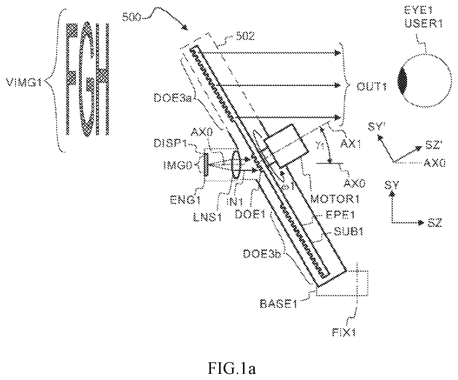
a shows, by way of example, in a side view, a display apparatus.
b shows, by way of example, in an axial view, an effective display region formed by rotating out-coupling elements.
c shows, by way of example, in a three-dimensional view, the display apparatus when the rotation angle is 90°.
d shows, by way of example, in a three-dimensional view, the display apparatus when the rotation angle is 0°.
a shows, by way of example, a timing diagram for light emission from a predetermined point of the display region.
b shows, by way of example, temporal evolution of coupling efficiency for forming first guided light, and temporal evolution of coupling efficiency for forming second guided light.
a shows, by way of example, in a side view, observing an external object through a window of a vehicle.
b shows, by way of example, in a side view, receiving external light, from the external object through the window of the vehicle.
c shows, by way of example, in a side view, observing an external object through a window of a vehicle, wherein the window is also arranged to reflect output light towards the eye of a user.
a to 4 e show, by way of example, in a three-dimensional view, forming, input light beams by using an optical engine.
f shows, by way of example, in a three-dimensional view, viewing a, displayed virtual image.
g shows, by way of example, angular width of the displayed virtual image.
h shows, by way of example, angular height of the displayed virtual image.
i shows, by way of example, wave vectors of input light beams.
a shows, by way of example, in a cross-sectional side view, propagation of guided light in the waveguide plate.
b shows, by way of example, in a cross-sectional side view, coupling, light into the waveguide plate, and coupling light out of the waveguide plate.
a shows, by way of example, in an axial view, dimensions of diffractive elements.
b shows, by way of example, in an axial view, grating vectors of the in-coupling element.
DETAILED DESCRIPTION OF THE EMBODIMENTS
Referring to a to 1 d , the display apparatus 500 may comprise an optical engine ENG 1 to form input light IN 1 , an expander device EPE 1 to form output light OUT 1 by expanding input light IN 1 , and a motor MOTOR 1 to provide an enlarged display region REG 1 by rotating the expander device EPE 1 .
A user USER 1 of the display apparatus 500 may observe a displayed virtual image VIMG 1 when the output light OUT 1 impinges on the eye EYE 1 of the user.
The input light IN 1 may comprise a plurality of light beams propagating in different directions. Each light beam of the input light IN 1 may correspond to a different point of the input image IMG 0 . The input light beams may together constitute input light IN 1 .
The output light OUT 1 may comprise a plurality of light beams propagating in different directions. The output light OUT 1 may comprise a plurality of output light beams corresponding to different points of the virtual image VIMG 1 . The expander device EPE 1 may form the output light OUT 1 from the input light IN 1 such that the directions and the intensities of the light beams of the output light OUT 1 correspond to the points of the input image IMG 0 . The expander device may expand light of the input light beams. The expander device EPE 1 may form the output light beams by diffractively expanding the input light beams of the input light IN 1 . Each output light beam may propagate in the same direction as the corresponding input light beam. Consequently, the displayed virtual image VIMG 1 may represent the input image IMG 0 .
A light beam of the input light IN 1 may correspond to a single image point (e.g. point P 0 ) of a displayed image. The expander device EPE 1 may form an output light beam from a light beam of the input light IN 1 such that the direction (k 3 P0,R ) of the output light beam is parallel with the direction (k 0 P0,R ) of the corresponding light beam of the input light IN 1 . A light beam corresponding to a different image point may propagate in a different direction. Directions and image points are shown e.g. in a to 4 i.
The optical engine ENG 1 may form input light IN 1 , which corresponds to an input image IMG 0 . The optical engine ENG 1 may form input light IN 1 , which represents an input image IMG 0 . The input light IN 1 may comprise a plurality of input light beams propagating in different directions corresponding to different image points of the input image IMG 0 . The optical engine ENG 1 may comprise a display DISP 1 and collimating optics LNS 1 to form the input light beams. The optical engine ENG 1 may project the input light IN 1 to the in-coupling element DOE 1 . The optical engine ENG 1 may also be called e.g. as a projector.
The rotating expander device EPE 1 may comprise a waveguide plate SUB 1 , which in turn may comprise an in-coupling element DOE 1 , and out-coupling elements DOE 3 a , DOE 3 b . The in-coupling element DOE 1 may couple the input light IN 1 into the waveguide plate SUB 1 . The input light IN 1 may impinge on the in-coupling element DOE 1 . The input light IN 1 may overlap the in-coupling element DOE 1 .
The axis AX 1 of rotation may intersect the in-coupling element DOE 1 . The in-coupling element DOE 1 may be concentric with the axis AX 1 of rotation. The optical axis AX 0 of the optical engine ENG 1 may intersect the in-coupling element DOE 1 . A distance between the optical axis AX 0 and the center of the in-coupling element DOE 1 may be e.g. smaller than 5% of the maximum width (w SUB1 ) of the waveguide plate SUB 1 . In particular, the optical axis AX 0 may intersect the center of the in-coupling element DOE 1 .
Each element DOE 1 , DOE 3 a , DOE 3 b may comprise one or more diffraction gratings. The gratings may be e.g. on the first and/or on the second surface of the waveguide plate SUB 1 . The elements DOE 1 , DOE 3 a , DOE 3 b may be diffractive elements. The in-coupling element DOE 1 may form guided light B 1 a , B 1 b by diffracting the input light IN 1 . The guided light B 1 a , B 1 b may propagate as waveguided light in the waveguide plate SUB 1 .
The out-coupling elements DOE 3 a , DOE 3 b may form output light OUT 1 by diffracting the guided light B 1 a , B 1 b out of the waveguide plate SUB 1 . The out-coupling elements DOE 3 a , DOE 3 b may operate as a pair of elements. The out-coupling elements DOE 3 a , DOE 3 b may be on opposite sides of the in-coupling element DOE 1 .
The expander device EPE 1 may be arranged to expand a viewing pupil of the display apparatus 500 , so as to facilitate keeping the eye EYE 1 of the user USER 1 in a suitable transverse position with respect to the display apparatus 500 .
γ 1 denotes the tilt angle between the optical axis AX 0 of the optical engine ENG 1 and the axis AX 1 of rotation of the expander device EPE 1 . The tilt angle γ 1 may be e.g. in the range of 10° to 45°. In particular, the tilt angle γ 1 may be e.g. in the range of 20° to 35°. The tilt angle γ 1 may be e.g. substantially equal to 30°. The inclined rotation axis AX 1 may cause that the input light IN 1 is coupled mainly to an upper region of the display area. Thus, the inclined rotation axis AX 1 may increase brightness of the upper display region, and/or may allow reducing the brightness of the input image IMG 0 . Reducing the brightness of the input image IMG 0 may allow reducing optical and electrical power of the optical engine ENG 1 .
The expander device EPE 1 may be arranged to rotate with respect to a stationary base BASE 1 . The display apparatus 500 may be mounted e.g. to a vehicle 1000 via the base BASE 1 . The display apparatus 500 may be mounted to a vehicle 1000 e.g. via one or more joints FIX 1 . The joints may be e.g. adhesive joints and/or screw joints.
The optical engine ENG 1 may have a fixed position with respect to the base BASE 1 . The optical engine ENG 1 may be fixedly mounted to the base BASE 1 . The optical engine ENG 1 may be stationary with respect to the base BASE 1 . The expander device EPE 1 may be arranged to move with respect to the stationary base BASE 1 . The expander device EPE 1 may be rotatable with respect to the stationary base BASE 1 . The expander device EPE 1 may be arranged to rotate and/or oscillate with respect to the stationary base BASE 1 .
The display apparatus 500 may comprise an actuating mechanism MOTOR 1 to cause rotary motion of the expander device EPE 1 with respect to the stationary base BASE 1 . The actuating mechanism MOTOR 1 may be directly or indirectly connected to the base BASE 1 . The actuating mechanism MOTOR 1 may be connected to the base BASE 1 e.g. via a protective cover 502 and/or via a frame. The actuating mechanism MOTOR 1 may be e.g. a motor. The actuating mechanism MOTOR 1 may be e.g. an electric motor or a pneumatic turbine. The motor MOTOR 1 may rotate the expander device EPE 1 about an axis AX 1 of rotation. The expander device EPE 1 may rotate at an angular velocity ω 1 , which corresponds to a speed of rotation f RPM .
The optical engine ENG 1 may be mechanically connected to the base BASE 1 e.g. via a protective cover 502 . The protective cover may be transparent or semi-transparent. For example, a transparent cover 502 may comprise clear glass or plastic. For example, semi-transparent cover 502 may comprise mesh, which has a see-through property. The protective cover 502 may also prevent the user from accidentally touching the rotating expander device EPE 1 .
The optical engine ENG 1 may be mechanically connected to the base BASE 1 also via a connecting structure. In an embodiment, the connecting structure may be an open structure. It is not always necessary to protect the rear side of the rotating expander device EPE 1 .
The in-coupling element DOE 1 may receive input light IN 1 , and the out-coupling elements may provide output light OUT 1 . The input light IN 1 may comprise a plurality of light beams propagating in different directions. The output light OUT 1 may comprise a plurality of expanded light beams (B 3 ) formed from the light beams (B 0 ) of the input light IN 1 .
The expander device EPE 1 forms an output light OUT 1 by expanding input light IN 1 . The width of the light beams of the output light OUT 1 may be greater than the width of the light beams of the input light IN 1 .
When rotating, the expander device EPE 1 may sequentially increase the horizontal cross-sectional dimension and the vertical cross-sectional dimension of the output light beams of the output light OUT 1 . When rotating, the expander device EPE 1 may effectively expand the input light IN 1 in two dimensions (e.g. in the direction SX and in the direction SY). The expansion process may also be called as exit pupil expansion. The expander device EPE 1 may be called as a beam expander device or as an exit pupil expander.
The in-coupling element DOE 1 may form guided light B 1 by coupling input light IN 1 into the waveguide plate SUB 1 . The in-coupling element DOE 1 may form guided light B 1 a ,B 1 b by coupling input light IN 1 into the waveguide plate SUB 1 . The guided light B 1 , B 1 a , B 1 b may be waveguided within the planar waveguide plate SUB 1 . The B 1 , B 1 a , B 1 b may be confined to the plate SUB 1 by total internal reflection. The term “guided” may mean that the light propagates within the planar waveguide plate SUB 1 so that the light is confined to the plate by total internal reflection (TIR). The waveguide plate SUB 1 operates as a light guide. The term “guided” may mean the same as the term “waveguided”.
SX, SY and SZ denote orthogonal directions of a first coordinate system. The optical axis AX 0 of the optical engine ENG 1 is parallel with the direction SZ. The directions SX and SY are perpendicular to the optical axis AX 0 .
SX, SY′ and SZ′ denote orthogonal directions of a second coordinate system. The direction SZ′ is parallel with the axis AX 1 of rotation of the expander device EPE 1 . The directions SX and SY′ are perpendicular to the axis AX 1 . The second coordinate system (SX, SY′, SZ′) is tilted with respect to the first coordinate system (SX, SY, SZ). The direction SX of the second coordinate system may be parallel with the direction SX of the first coordinate system.
The waveguide plate SUB 1 may be parallel with a plane defined by the directions SX and SY′.
The expander device EPE 1 may be rotatable relative to the base BASE 1 . The in-coupling element DOE 1 may be concentric with the axis AX 1 of rotation.
The actuating mechanism MOTOR 1 may be arranged to rotate the waveguide plate SUB 1 at a rotation speed f RPM , which is e.g. in the range of 5 to 200 revolutions per second.
For example, the motor MOTOR 1 may be arranged to rotate the expander device EPE 1 so that the rotation speed f RPM of the expander device EPE 1 is greater than or equal to 30 revolutions per second. Consequently, it may be difficult to visually detect flickering of the displayed image VIMG 1 .
For example, the motor MOTOR 1 may be arranged to rotate the expander device EPE 1 so that the rotation speed f RPM of the expander device EPE 1 is greater than or equal to 60 revolutions per second. Consequently, it may be more difficult to visually detect flickering of the displayed image VIMG 1 .
In an embodiment, the expander device EPE 1 may be rotatably supported by the one or more bearings of the motor MOTOR 1 .
The motor MOTOR 1 and the optical engine ENG 1 may be on different sides of the expander device EPE 1 ( a ) or on the same side of the expander device EPE 1 . For example, the motor MOTOR 1 may have a central opening (HOL 1 ), so as to allow positioning the motor MOTOR 1 and the optical engine ENG 1 on the same side of the expander device EPE 1 . Consequently, the motor does not block output light OUT 1 .
In an embodiment, the expander device EPE 1 and/or the motor MOTOR 1 may block a central region of the display region REG 1 , so that the primary display region REG 1 has a dark center.
The expander device EPE 1 may be mechanically balanced with respect to the axis AX 1 of rotation, so as to minimize or eliminate mechanical vibration caused by the rotation of the expander device EPE 1 .
The expander device EPE 1 may be statically balanced so that the center of gravity of the expander device EPE 1 may be on the axis AX 1 of rotation.
The expander device EPE 1 may be dynamically balanced so that rotation about the axis AX 1 does not generate any resultant centrifugal force. The expander device EPE 1 may be dynamically balanced so that rotation about the axis AX 1 does not generate any significant resultant centrifugal force.
Referring to b , the out-coupling elements DOE 3 a , DOE 3 b may generate a large display area DAR 1 by sweeping along a circular path PATH 1 around the axis AX 1 of rotation of the expander device EPE 1 .
The display area DAR 1 may have a primary region REG 1 and a secondary region REG 2 . The primary region REG 1 may be e.g. an upper region of the display area DAR 1 , and the secondary region REG 2 may be a lower region of the display area DAR 1 . The axis AX 1 of rotation may be tilted such that the intensity of output light OUT 1 projected from the primary region REG 1 may be higher than the intensity of output light OUT 1 projected from the secondary region REG 2 .
The primary region REG 1 may be defined by an outer boundary BND 1 , by an inner boundary BND 2 , by a left boundary BND 3 and by a right boundary BND 4 . The boundaries BND 1 , BND 2 may be concentric with the axis AX 1 of rotation.
The primary region REG 1 may have an outer radius r 1 REG1 . The primary region REG 1 may have an inner radius r 2 REG1 . The out-coupling elements DOE 3 a , DOE 3 b may define the outer boundary BND 1 and/or the inner boundary BND 2 of the primary region REG 1 . The radius r 1 REG1 of the outer boundary BND 1 may be e.g. in the range of 4 cm to 25 cm. The width w REG1 of the primary display region REG 1 may be e.g. in the range of 8 cm to 50 cm. The surface area A REG1 of the primary display region REG 1 may be e.g. in the range of 100 cm 2 to 1500 cm 2 .
w REG1 may denote the width of the primary region REG 1 . h REG1 may denote the height of the primary region REG 1 in the middle of the primary region REG 1 . A REG1 denotes the effective surface area of the primary display region REG 1 . A DOE3a denotes the surface area of an out-coupling element DOE 3 a . f RPM denotes the speed of rotation of the expander device EPE 1 .
The rotation angle ϕ a a may specify the angular position of the first out-coupling element DOE 3 a . The rotation angle ϕ a (t) may be a function of time t. The rotation angle ϕ a (t) may be determined e.g. by the following equation: ϕ a ( t )=ω 1 ·t+C 1 (1)
where ω 1 denotes the angular speed of the rotating expander device EPE 1 , and C 1 denotes an initial angle. The rotation angle ϕ a may e.g. specify an angle between the direction SX and a line drawn from the center point CPa of the element DOE 3 a to the axis AX 1 .
The center point CPa of the element DOE 3 a moves along a circular path PATH 1 around the axis AX 1 . The center point CPa moves together with the rotating expander device EPE 1 . The display points DP 1 , DP 2 , DP 3 , DP 4 are stationary points of the display area DAR 1 . The display points DP 1 , DP 2 , DP 3 , DP 4 have a fixed position with respect to the base BASE 1 . DP 1 denotes a first display point, which coincides with the center point CPa of the element DOE 3 a when the center point CPa is located at the rotation angle ϕ a =0°. DP 2 denotes a second display point, which coincides with the center point CPa when the center point CPa is located at the rotation angle ϕ a =90°. DP 3 denotes a third display point, which coincides with the center point CPa when the center point CPa is located at the rotation angle ϕ a =180°. DP 4 denotes a fourth display point, which coincides with the center point CPa when the center point CPa is located at the rotation angle ϕ a =270°.
An arbitrary point (e.g. POINT 1 ) of the primary display region REG 1 may have a fixed position with respect to the base BASE 1 . The arbitrary point (POINT 1 ) may emit output light OUT 1 in a pulsed manner when the expander device EPE 1 rotates so that said point (POINT 1 ) is within the area of an out-coupling element (e.g. DOE 3 a ). The emission of output light OUT 1 from said point (POINT 1 ) may be periodically stopped when the out-coupling element (e.g. DOE 3 a ) moves so that the point (POINT 1 ) is outside the area of the out-coupling elements (DOE 3 a , DOE 3 b ). The speed of rotation (f RPM ) may be selected to be high enough so as to reduce or avoid visually detectable flickering of said point (POINT 1 ) of the display region (REG 1 ).
Each point of the primary display region REG 1 may sequentially emit output light OUT 1 in a pulsed manner when the out-coupling elements DOE 3 a , DOE 3 b sweep over said point. The whole primary display region REG 1 may emit output light OUT 1 in a pulsed manner.
a shows, by way of example, a timing diagram for the local intensity I DP2 of the display point DP 2 , when displaying a virtual image VIMG 1 . The DP 2 appears to emit light to the eye EYE 1 in a pulsed manner when the expander device EPE 1 rotates. The intensity of the point POINT 1 reaches a maximum value I MAX when the point DP 2 overlaps an out-coupling element DOE 3 a or DOE 3 b . The intensity of the point DP 2 is zero when the point DP 2 does not overlap any of the out-coupling elements. T ROT denotes a time period for one full rotation of the expander device EPE 1 . The time period T ROT is equal to 1/f RPM . T ON denotes a time period during which the point DP 2 is within the area of a moving out-coupling element. The symbol TON also denotes the duration of a light pulse emitted from the point DP 2 when an out-coupling element sweeps over said point DP 2 . T BLANK denotes a time period during which the point DP 2 is outside the area of the out-coupling elements. The point DP 2 is within the area of the out-coupling element DOE 3 a between times t 1a ,t′ 1a , between times t 2a ,t′ 2a , between times t 3a ,t′ 3a , and between times t 4a ,t′ 4a . The point DP 2 is within the area of the out-coupling element DOE 3 b between times t 1b ,t′ 1b , between times t 2b ,t′ 2b , and between times t 3b ,t′ 3b .
b shows in-coupling efficiencies (η 1 ) for forming guided light from the input light. The solid curve of b shows, by way of example, a first coupling efficiency η 1a (ϕ a ) for forming first guided light B 1 a from the input light IN 1 , as a function of the rotation angle ϕ a . The dashed curve of b shows, by way of example, a second coupling efficiency η 1b (ϕ a ) for forming second guided light B 1 b from the input light IN 1 , as a function of the rotation angle ϕ a . The coupling efficiencies of b represent a situation where the tilt angle γ 1 is equal to 30°.
The first coupling efficiency η 1a (ϕ a ) may be e.g. higher than 30% when the rotation angle ϕ a is in the range of 30° to 150°. The first coupling efficiency η 1a (ϕ a ) may be e.g. lower than or equal to 5% when the rotation angle ϕ a is in the range of 180° to 360°.
The second coupling efficiency η 1b (ϕ a ) may be e.g. higher than 30% when the rotation angle ϕ a is in the range of 210° to 330°. The coupling efficiency η 1b (ϕ a ) may be e.g. lower than or equal to 5% when the rotation angle ϕ a is in the range of 0° to 180°.
The coupling efficiency η 1a (ϕ a ) may also be called as in-coupling efficiency. The coupling efficiency η 1b (ϕ a ) may also be called as in-coupling efficiency. The first coupling efficiency η 1a (ϕ a ) may mean the ratio of the power of the first guided light B 1 a to the ratio of the power of the input light IN 1 impinging on the in-coupling element DOE 1 . The second coupling efficiency η 1b (ϕ a ) may mean the ratio of the power of the second guided light B 1 b to the ratio of the power of the input light IN 1 impinging on the in-coupling element DOE 1 .
The coupling efficiencies of b indicate that the in-coupling element DOE 1 may couple input light IN 1 mainly to the primary portion REG 1 of the display area DAR 1 . Consequently, the upper primary portion REG 1 may appear to be brighter than the lower secondary portion REG 2 .
The left boundary BND 3 and the right boundary BND 4 of the primary display region REG 1 may be defined based on the angular coupling efficiency functions η 1a (ϕ a ), η 1a (ϕ a ) of the expander device EPE 1 . For example, the right boundary BND 4 may be defined by a lowermost edge of the first out-coupling element DOE 3 a at a first rotation angle ϕ a where the coupling efficiency function η 1a (ϕ a ) increases to 5% (e.g. when ϕ a =0°). For example, the left boundary BND 3 may be defined by a lowermost edge of the first out-coupling element DOE 3 a at a second rotation angle ϕ a where the coupling efficiency function η 1a (ϕ a ) decreases to 5% (e.g. when ϕ a =180°).
Referring to a to 3 c , the display apparatus 500 may be a vehicle-mounted head-up display. A vehicle 1000 may comprise the display apparatus 500 . The vehicle may be e.g. an electric car propelled by an electric motor. The vehicle may be e.g. a car propelled by an internal combustion engine. The vehicle may be e.g. a motorcycle. The vehicle may be e.g. a tram. The vehicle may be e.g. a train.
When driving a vehicle, a driver USER 1 may need to observe information related to the driving. The display apparatus 500 of the vehicle may be arranged to display information about the speed of the vehicle, status of a battery, status of a motor of the vehicle, and/or navigation instructions, for example. The user USER 1 of the display apparatus 500 may be the driver or a passenger of the vehicle. The user USER 1 may see real objects OBJ 1 and/or environment through the display region REG 1 , in addition to the displayed virtual images VIMG 1 . When using the display apparatus 500 , the driver USER 1 does not need to look down at the dashboard in order to observe the displayed information. When using the display apparatus 500 , the driver USER 1 may continuously observe the environment through the windscreen of the vehicle, without a need to look down. Avoiding the need to look down may improve driving safety. The displayed virtual image VIMG 1 may represent the information, which is related to the driving. The virtual image VIMG 1 formed by the display apparatus 500 may fall in front of the driver's line of sight LIN 1 , so that driver USER 1 can observe displayed information and external objects at the same time. The driver's line of sight LIN 1 may intersect the effective display area REG 1 of the display apparatus 500 .
Rotation of the expander device EPE 1 may provide a larger display region REG 1 by using smaller out-coupling elements. This may provide a large eye box BOX 1 for the user USER 1 . The user may observe the displayed virtual image VIMG 1 as long as the eye EYE 1 of the user remains within the eye BOX 1 of the display apparatus 500 . The rotating expander device EPE 1 may provide a uniform spatial intensity distribution for the output light OUT 1 . The rotating expander device EPE 1 may provide a high image quality. The smaller out-coupling elements may be easier and/or cheaper to produce than large out-coupling elements.
The large display region REG 1 may also facilitate displaying a virtual image VIMG 1 , which has a large angular width Δφ and/or a large angular height Δθ. Thanks to the large display region, the user may see the whole virtual image VIMG 1 , or at least a large part of the virtual image VIMG 1 also when the distance between the eye EYE 1 and the expander device EPE 1 is large. The virtual image VIMG 1 may cover a large field of view. The virtual image VIMG 1 may comprise e.g. vehicle information and/or navigation information.
The display apparatus 500 may be mounted to the vehicle 1000 via the base BASE 1 . For example, the base BASE 1 may be mounted to the window WIN 1 , to a dashboard, or to a ceiling of a vehicle 1000 .
The eye EYE 1 of the user USER 1 may receive external light EX 1 from an external object OBJ 1 . The user USER 1 may observe the external object OBJ 1 when the external light EX 1 impinges on the eye EYE 1 . The external light EX 1 may propagate through the window WIN 1 and through the display area REG 1 of the apparatus 500 to the eye EYE 1 of the user USER 1 . The user USER 1 may simultaneously observe the external object OBJ 1 and the displayed virtual image VIMG 1 .
Referring to c , the window WIN 1 may be arranged to operate as a part of the display apparatus 500 . The window WIN 1 may be e.g. the windscreen of the vehicle 1000 . The window WIN 1 may reflect the output light OUT 1 towards the user EYE 1 so that the user may view the displayed virtual image VIMG 1 , wherein the user EYE 1 may simultaneously observe the environment of the vehicle 1000 through the window WIN 1 . For example, the line of sight LIN 1 from the external object OBJ 1 to the eye EYE 1 may intersect the display area REG 1 . For example, the user may observe an external object OBJ 1 through the window WIN 1 so that the displayed virtual image VIMG 1 may visually overlap the external object OBJ 1 . The driver may be visually immersed in the environment of the vehicle while viewing the displayed virtual image so that the driver does not need to look down.
The window WIN 1 may be a planar (flat) transparent window or a curved transparent window. The planar window may reflect the output light OUT 1 without deforming the displayed virtual image VIMG 1 .
A curved window may deform the displayed virtual image VIMG 1 . The display apparatus 500 may be arranged to at least partly compensate deformation of the virtual image VIMG 1 .
The window WIN 1 may simultaneously transmit external light EX 1 and reflect output light OUT 1 to the eye EYE 1 of the user USER 1 . The window WIN 1 may operate as a semi-transparent reflector, which may simultaneously transmit external light EX 1 and reflect output light OUT 1 . The external light EX 1 may propagate through the window WIN 1 to the eye EYE 1 .
In an embodiment, the window WIN 1 may be coated with a semi-transparent reflective coating, e.g. in order to increase the intensity of the reflected output light. The coating may be e.g. a dielectric or metallic coating.
In an embodiment, the semi-transparent reflective window WIN 1 may also operate based on Fresnel reflection caused by the difference between the refractive index of the window and the refractive index of air. The semi-transparent reflective window WIN 1 does not need to comprise a reflective coating.
Referring to a to 4 e , the expander device EPE 1 may form output light OUT 1 by expanding input light IN 1 formed by the optical engine ENG 1 .
The optical engine ENG 1 may comprise a display DISP 1 and collimating optics LNS 1 . The display DISP 1 may be arranged to display an input image IMG 0 . The display DISP 1 may also be called e.g. as a micro display. The display DISP 1 may also be called e.g. as a spatial intensity modulator. The input image IMG 0 may also be called e.g. as a primary image.
The input image IMG 0 may comprise a center point P 0 and four corner points P 1 , P 2 , P 3 , P 4 . P 1 may denote an upper left corner point. P 2 may denote an upper right corner point. P 3 may denote a lower left corner point. P 4 may denote a lower right corner point. The input image IMG 0 may comprise e.g. the graphical characters “F”, “G”, and “H”. The input image IMG 0 may represent displayed information.
The input image IMG 0 may be e.g. a single-color image. A single-color image IMG 0 may be formed e.g. by modulating laser light or by modulating light obtained from one or more light emitting diodes.
The input image IMG 0 may also be a multi-color image. The input image IMG 0 may be e.g. an RGB image, which may comprise a red partial image, a green partial image, and a blue partial image. Each image point may provide e.g. red light, green light and/or blue light.
The optical engine ENG 1 may provide input light IN 1 , which may comprise a plurality of substantially collimated light beams (B 0 ). For example, each red light beam may propagate in a different direction and may correspond to a different point of the input image IMG 0 . Each light beam may have a color. For example, the subscript “R” may refer to the red color. For example, a red light beam B 0 P1,R may correspond to an image point P 1 , and may propagate in the direction of a wave vector k 0 P1,R . The red light beam corresponding to the image point P 1 may propagate in the direction specified by the wave vector k 0 P1,R .
A red light beam B 0 P2,R may correspond to an image point P 2 , and may propagate in the direction of a wave vector k 0 P2,R . A red light beam B 0 P3,R may correspond to an image point P 3 , and may propagate in the direction of a wave vector k 0 P3,R . A red light beam B 0 P4,R may correspond to an image point P 4 , and may propagate in the direction of a wave vector k 0 P4,R .
A red light beam B 0 P0,R may correspond to a central image point P 0 , and may propagate in the direction of a wave vector k 0 P0,R .
Also a blue light beam (B 0 P1,B ) may correspond to the image point P 1 , and may propagate in the direction of a wave vector (k 0 P1,B ).
The input light IN 1 may be formed e.g. such that the direction (k 0 P1,B ) of propagation of the blue light beam (B 0 P1,B ) corresponding to a first corner point P 1 of the input image IMG 0 may be parallel with the direction k 0 P1,R of propagation of the red light beam B 0 P1,R .
The input light IN 1 may be formed e.g. such that the direction (k 0 P2,B ) of propagation of a blue light beam (B 0 P2,B ) corresponding to a second corner point P 2 of the input image IMG 0 may be parallel with the direction (k 0 P2,R ) of propagation of a red light beam (B 0 P2,R ), which corresponds to said second corner point P 2 .
The wave vector (k) of light may be defined as the vector having a direction of propagation of said light, and a magnitude given by 2π/λ, where λ is the wavelength of said light.
The light B 0 P0,R of the center point P 0 may propagate in an axial direction (k 0 P0,R ). The axial direction (k 0 P0,R ) may be parallel with an optical axis (AX 0 ) of the optical engine ENG 1 .
Referring to f , the output light OUT 1 may comprise a plurality of output light beams B 3 P1,R , B 3 P2,R , . . . , which may correspond to a displayed virtual image VIMG 1 . Each output beam B 3 P1,R , B 3 P2,R , . . . may correspond to a point P 1 ′, P 2 ′, . . . of the image. For example, a red light beam B 3 P0,R propagating in a direction of a wave vector k 3 P0,R may correspond to a point P 0 ′ of the image VIMG 1 . A red light beam B 3 P1,R propagating in a direction of a wave vector k 3 P1,R may correspond to a point P 1 ′ of the image VIMG 1 . A red light beam B 3 P2,R propagating in a direction of a wave vector k 3 P2,R may correspond to a point P 2 ′ of the image VIMG 1 . A red light beam B 3 P3,R propagating in a direction of a wave vector k 3 P3,R may correspond to a point P 3 ′. A red light beam B 3 P4,R propagating in a direction of a wave vector k 3 P4,R may correspond to a point P 4 ′.
The expander device EPE 1 may form the output light OUT 1 by expanding the exit pupil of the optical engine ENG 1 . The output light OUT 1 may comprise a plurality of output light beams, which correspond to the displayed virtual image VIMG 1 . The output light OUT 1 may impinge on the eye EYE 1 of an observer such that the observer may see the displayed virtual image VIMG 1 .
The displayed virtual image VIMG 1 may have a center point P 0 ′ and four corner points P 1 ′, P 2 ′, P 3 ′, P 4 ′. The input light IN 1 may comprise a plurality of partial light beams corresponding to the points P 0 , P 1 , P 2 , P 3 , P 4 of the input image IMG 0 . The expander device EPE 1 may form the point P 0 ′ of the displayed virtual image VIMG 1 e.g. by diffracting and guiding light of the point P 0 of the input image IMG 0 . The in-coupling element DOE 1 may be arranged to diffract input light IN 1 such that the guided light B 1 , B 1 a , B 1 b comprises light of a center point P 0 of an input image IMG 0 . The out-coupling element DOE 3 , DOE 3 a , DOE 3 b may be arranged to diffract guided light B 1 , B 1 a , B 1 b received from the in-coupling element DOE 1 such that the output light OUT 1 comprises light of the center point P 0 .
The expander device EPE 1 may form the points P 1 ′, P 2 ′, P 3 ′, P 4 ′ e.g. by diffracting and guiding light of the points P 1 , P 2 , P 3 , P 4 , respectively.
The expander device EPE 1 may form output light OUT 1 , which comprises a plurality of light beams B 3 P0,R , B 3 P1,R , B 3 P2,R , B 3 P3,R , B 3 P4,R propagating in different directions specified by the wave vectors k 3 P0,R , k 3 P1,R , k 3 P2,R , k 3 P3,R , k 3 P4,R .
A red light beam corresponding to the point P 0 ′ of the displayed virtual image VIMG 1 has a wave vector k 3 P0,R . A red light beam corresponding to the point P 1 ′ has a wave vector k 3 P1,R . A red light beam corresponding to the point P 2 ′ has a wave vector k 3 P2,R . A red light beam corresponding to the point P 3 ′ has a wave vector k 3 P3,R . A red light beam corresponding to the point P 4 ′ has a wave vector k 3 P4,R .
The expander device EPE 1 may expand input light IN 1 such that each output light beam B 3 P1,R , B 3 P2,R , B 3 P3,R , . . . may propagate in the same direction as the corresponding input light beam B 0 P1,R , B 0 P2,R , B 0 P3,R , . . . . For example, the expander device EPE 1 may form an output light beam B 3 P1,R from light of an input light beam B 0 P1,R such that the output light beam B 3 P1,R propagates in the same direction as the input light beam B 0 P1,R . The light beams B 0 P1,R , B 3 P1,R may correspond to the same point P 1 of the input image IMG 0 . For example, the expander device EPE 1 may form an output light beam B 3 P2,R from light of an input light beam B 0 P2,R such that the output light beam B 3 P2,R propagates in the same direction as the input light beam B 0 P2,R . The light beams B 0 P2,R , B 3 P2,R may correspond to the same point P 2 of the input image IMG 0 .
The expander device EPE 1 may be arranged to operate such that the wave vector k 3 P1,R is parallel with the wave vector k 0 P1,R of red light of the point P 1 in the input light IN 1 . The wave vector k 3 P0,R may be parallel with the wave vector k 0 P0,R of the point P 0 . The wave vector k 3 P2,R may be parallel with the wave vector k 0 P2,R of the point P 2 . The wave vector k 3 P3,R may be parallel with the wave vector k 0 P3,R of the point P 3 . The wave vector k 3 P4,R may be parallel with the wave vector k 0 P4,R of the point P 4 .
Referring to g and 4 h , the displayed virtual image VIMG 1 has an angular width Δφ and an angular height Δθ.
The displayed virtual image VIMG 1 may have a first corner point P 1 ′ e.g. at the left-hand side of the image VIMG 1 , and a second corner point P 2 ′ e.g. at the right-hand side of the image VIMG 1 . The angular width Δφ of the virtual image VIMG 1 may be equal to the horizontal angle between the wave vectors k 3 P1,R , k 3 P2,R of the corner points P 1 ′, P 2 ′.
The displayed virtual image VIMG 1 may have an upper corner point P 1 ′ and a lower corner point P 3 ′. The angular height Δθ of the virtual image VIMG 1 may be equal to the vertical angle between the wave vectors k 3 P1,R , k 3 P3,R of the corner points P 1 ′, P 3 ′.
The direction of a wave vector may be specified e.g. by orientation angles φ and θ. The angle φ may denote an angle between the wave vector and a reference plane REF 1 . The reference plane REF 1 may be defined e.g. by the directions SZ and SY. The angle θ may denote an angle between the wave vector and a reference plane REF 2 . The reference plane REF 2 may be defined e.g. by the directions SZ and SX.
Referring to i , the input light IN 1 may comprise red light (R), green light (G) and/or blue light (B). For example, the input light IN 1 may comprise blue input light beams B 0 P0,B , B 0 P1,B , B 0 P2,B , B 0 P3,B , B 0 P4,B , which have wave vectors k 0 P0,B , k 0 P1,B , k 0 P2,B , k 0 P3,B , k 0 P4,B , corresponding to blue points P 0 , P 1 , P 2 , P 3 , P 4 of the image IMG 0 .
For example, the notation k 0 P2,B may refer to the wave vector of an input light beam B 0 P2,B , which has blue color (B), and which corresponds to an image point P 2 .
The expander device EPE 1 may form blue output light beams from the blue input light beams such that the wave vector of each blue output light beams is parallel with the wave vector of the corresponding blue input light beam.
Referring to a , the optical engine ENG 1 may form an input image IMG 0 and may convert the input image IMG 0 into a plurality of light beams of the input light IN 1 . The engine ENG 1 may be optically coupled to the in-coupling element DOE 1 of the expander EPE 1 . The one or more light beams provided by the engine ENG 1 may be coupled to the expander EPE 1 as input light IN 1 . The input light IN 1 may be optically coupled to the in-coupling element DOE 1 of the expander device EPE 1 .
The first out-coupling element DOE 3 a may form a portion B 3 a of output light OUT 1 by diffracting first guided light B 1 a out of the substrate plate SUB 1 . The second out-coupling element DOE 3 b may form a second portion B 3 b of output light OUT 1 by diffracting guided light B 1 b.
The input image IMG 0 may be represent displayed information. The input image IMG 0 may be represent e.g. graphics and/or text. The input image IMG 0 may be represent e.g. video. The engine ENG 1 may be arranged to generate still images and/or video. The engine ENG 1 may generate a real primary image IMG 0 from a digital image. The engine ENG 1 may receive one or more digital images e.g. from an internet server or from a smartphone.
The expander device EPE 1 may carry virtual image content from the light engine ENG 1 to the front of a user's eye EYE 1 . The expander device EPE 1 may expand the viewing pupil, thus enlarging the eye box.
The engine ENG 1 may comprise a micro-display DISP 1 to generate an input image IMG 0 . The micro-display DISP 1 may comprise a two-dimensional array of light-emitting pixels. The engine ENG 1 may comprise e.g. one or more light emitting diodes (LED). The display DISP 1 may comprise e.g. one or more micro display imagers, such as liquid crystal on silicon (LCOS), liquid crystal display (LCD), digital micromirror device (DMD). The display DISP 1 may generate an input image IMG 0 e.g. at a resolution of 1280×720 (HD). The display DISP 1 may generate an input image IMG 0 e.g. at a resolution of 1920×1080 (Full HD). The display DISP 1 may generate an input image IMG 0 e.g. at a resolution of 3840×2160 (4K UHD). The input image IMG 0 may comprise a plurality of image points P 0 , P 1 , P 2 , . . . . The engine ENG 1 may comprise collimating optics LNS 1 to form a different light beam from each image pixel. The engine ENG 1 may comprise collimating optics LNS 1 to form a substantially collimated light beam from light of an image point P 0 . The center of the display DISP 1 and the center of the optics LNS 1 may together define an optical axis AX 0 of the engine ENG 1 . The orientation of the optical axis AX 0 of the optical engine ENG 1 is fixed with respect to the optical engine ENG 1 . The orientation of the optical axis AX 0 is fixed with respect to the display DISP 1 . The center point of the active area of the display DISP 1 and the center of the optics LNS 1 may together define the optical axis AX 0 . The center point (P 0 ) of the input image (IMG 0 ) may coincide with the center point of the active area of the display DISP 1 . The symbol P 0 may also refer to the center point of the active controllable display area of the display DISP 1 .
The optical axis AX 0 may be parallel with an axial light beam (B 3 P0,R ) of the input light (IN 1 ), wherein said axial light beam (B 3 P0,R ) corresponds to a center point (P 0 ) of the input image (IMG 0 ).
The optical engine ENG 1 may be arranged to simultaneously project red light, green light, and blue light, so as to display a multi-color image VIMG 1 .
The optical engine ENG 1 may be arranged to project only one color (e.g. red, green or blue). The expander device may be arranged to display a single-color image VIMG 1 .
The plate SUB 1 may have a first major surface SRF 1 and a second major surface SRF 2 . The surfaces SRF 1 , SRF 2 may be substantially parallel with the plane defined by the directions SX and SY′.
The waveguide plate SUB 1 may comprise or consist essentially of transparent solid material. The plate SUB 1 may comprise e.g. glass, polycarbonate or polymethyl methacrylate (PMMA). The diffractive optical elements DOE 1 , DOE 3 a , DOE 3 b may be formed e.g. by molding, embossing, and/or etching. The diffractive optical elements may be implemented e.g. by one or more surface diffraction gratings or by one or more volume diffraction gratings.
In particular, the in-coupling element DOE 1 may comprise a surface relief diffraction grating, so as to enhance the effect of the tilt angle γ 1 on the distribution of light to the upper and lower regions REG 1 , REG 2 of the display area DAR 1 .
In an embodiment, the diffractive elements may be produced by using lithographic techniques. For example, an embossing tool may be produced by e-beam lithography, and the diffraction gratings of the out-coupling elements may be formed by using the embossing tool. Increasing the size of the micro-structured area of the embossing tool may significantly increase production costs of the embossing tool. The rotating expander device may provide an enlarged display area without the need to increase the size of the micro-structured area of the embossing tool.
The waveguide plate may have a thickness t SUB1 . The waveguide plate comprises a planar waveguiding core. In an embodiment, the plate SUB 1 may optionally comprise e.g. one or more cladding layers, one or more protective layers, and/or one or more mechanically supporting layers. The thickness t SUB1 may refer to the thickness of a planar waveguiding core of the plate SUB 1 .
Referring to b , the optical engine ENG 1 may form a light beam B 0 P0,R , which represents the red color component of the image point P 0 . The in-coupling element DOE 1 may form first guided light B 1 a P0,R and second guided light B 1 b P0,R by diffracting light of the light beam B 0 P0,R . The first out-coupling element DOE 3 a may form an output light beam B 3 a P0,R by diffracting the first guided light B 1 a P0,R . The second out-coupling element DOE 3 b may form an output light beam B 3 b P0,R by diffracting the second guided light B 1 b P0,R .
The in-coupling element DOE 1 comprises diffractive features F 1 a . The out-coupling coupling element DOE 3 a comprises diffractive features F 3 a . The out-coupling coupling element DOE 3 b comprises diffractive features F 3 b . The in-coupling element DOE 1 has a grating period d 1a . The out-coupling coupling element DOE 3 a has a grating period d 3a . The out-coupling coupling element DOE 3 b has a grating period d 3b .
The out-coupling elements may be arranged to form the output light beams such that the direction and the intensity of each output light beam may correspond to the position and the brightness of the corresponding image point of the displayed image VIMG 1 .
The positions and the orientation of the diffractive features of the out-coupling elements may be selected such that output light beams formed by the different out-coupling elements are parallel with each other, in a situation where said output light beams correspond to the same image point of the displayed image.
For example, the out-coupling element DOE 3 a may form an output light beam B 3 a P0,R , and the out-coupling element DOE 3 b may form an output light beam B 3 b P0,R such that the output light beams B 3 a P0,R , B 3 b P0,R formed by the different out-coupling elements are parallel with each other, in a situation where the output light beams correspond to the same image point (P 0 ) of the displayed image VIMG 1 . The subscript “R” may refer to red color.
The parallel output light beams may ensure that the displayed image point (P 0 ) visually appears as a single point, and the parallel output light beams may also ensure that rotation of the expander device EPE 1 does not cause visually detectable shifting of the displayed image point (P 0 ).
The diffractive features Fla of the tilted in-coupling element DOE 1 may be inclined with respect to the optical axis AX 0 of the optical engine ENG 1 . A first coupling efficiency for forming a first guided light beam B 1 a P0,R from an axial input beam B 0 P0,R may be different from a second coupling efficiency for forming a second guided light beam B 1 b P0,R from the axial input beam B 0 P0,R .
Referring to a , each element DOE 1 , DOE 3 a , DOE 3 b may comprise one or more diffraction gratings to diffract light. The in-coupling element DOE 1 may comprise one or more diffraction gratings G 1 . The out-coupling element DOE 3 a may comprise a diffraction grating G 3 a . The out-coupling element DOE 3 b may comprise a diffraction grating G 3 b.
The grating period (d) of a diffraction grating and the orientation ( 13 ) of the diffractive features of the diffraction grating may specify a grating vector V of said diffraction grating. The diffraction grating comprises a plurality of diffractive features (F 1 a ,F 3 a ,F 3 b ) which may operate as diffractive lines. The diffractive features may be e.g. microscopic ridges or grooves. The diffractive features may be e.g. microscopic protrusions (or recesses), wherein adjacent rows of protrusions (or recesses) may operate as diffractive lines. The grating vector V may be defined as a vector having a direction perpendicular to diffractive lines of the diffraction grating and a magnitude given by 2π/d, where d is the grating period. The grating period means the same as the grating period length. The grating period may be the length between consecutive diffractive features of the grating. The grating period may be equal to a unit length divided by the number of diffractive features located within said unit length. The grating period di a of the in-coupling element DOE 1 may be e.g. in the range of 330 nm to 450 nm. The optimum value of a grating period d may depend e.g. on the refractive index of the plate SUB 1 and on the wavelength λ of the diffracted light.
The grating periods (d) and the orientations (β) of the diffraction gratings of the optical elements may be selected such that the direction (k 3 P0,R ) of propagation of light of the center point P 0 in the output light OUT 1 is parallel with the direction (k 0 P0,R ) of propagation of light of the center point P 0 in the input light IN 1 .
The grating periods (d) and the orientations (β) of the diffraction gratings of the optical elements DOE 1 , DOE 3 a , DOE 3 b may be selected such that the direction of each light beam of the output light OUT 1 may be parallel with the direction of the corresponding light beam of the input light IN 1 .
The in-coupling element DOE 1 has a first grating vector V 1a and a second grating vector V 1b . The magnitude of the grating vectors V 1a may be determined by a grating period di a of a diffraction grating G 1 of the in-coupling element DOE 1 . The diffraction grating G 1 may comprise diffractive features F 1 a . The orientation of the first grating vector V 1a may be specified by an angle β 1a with respect to a reference direction.
The reference direction may be e.g. the direction of the first grating vector V 1a , in which case the orientation angle β 1a is equal to zero (i.e. β 1a =0°). The reference direction may also be e.g. the direction SX in a situation where rotation of the expander device EPE 1 is stopped. The expander device EPE 1 may be rotated and stopped such that the first grating vector V 1a is parallel with the direction SX.
The in-coupling element DOE 1 has the first grating vector V 1a for forming the first guided light B 1 a by coupling the input light IN 1 into the waveguide plate SUB 1 . The in-coupling element DOE 1 has the second grating vector V 1b for forming the second guided light B 1 b by coupling the input light IN 1 into the waveguide plate SUB 1 .
The in-coupling element DOE 1 may form guided light B 1 a , B 1 b in the directions specified by the grating vectors V 1a , V 1b of the in-coupling element DOE 1 .
The first out-coupling element DOE 3 a has a diffraction grating G 3 a for coupling the first guided light B 1 a out of the plate SUB 1 . The grating G 3 a comprises diffractive features F 3 a , and has a grating period d 3a . The direction of the grating vector V 3a of the out-coupling element DOE 3 a is specified by the orientation angle 133 a.
The second out-coupling element DOE 3 b has a diffraction grating G 3 b for coupling the second guided light B 1 b out of the plate SUB 1 . The grating G 3 b comprises diffractive features F 3 b , and has a grating period d 3b . The direction of the grating vector V 3b of the out-coupling element DOE 3 b is specified by the orientation angle β 3b .
The first grating vector V 1a has a direction β 1a and a magnitude 2π/d 1a . The second grating vector V 1b has a direction β 1b and a magnitude 2π/d 1a . The grating vector V 3a has a direction β 3a and a magnitude 2π/d 3a . The grating vector V 3b has a direction β 3b and a magnitude 2π/d 3b . The direction (β) of a grating vector may be specified e.g. by the angle between said vector and a reference direction (e.g. direction SX).
The magnitude of the grating vector V 1b may be equal to the magnitude of the grating vector V 1a , and the direction of the grating vector V 1b may be opposite to the direction of the grating vector V 1a .
The first out-coupling element DOE 3 a may form a portion B 3 a of output light OUT 1 . The second out-coupling element DOE 3 b may form a portion B 3 b of output light OUT 1 . The grating vectors d 3a , d 3b of the out-coupling elements DOE 3 a , DOE 3 b may be selected such that light beams of the different portions B 3 a , B 3 b of the output light OUT 1 are parallel with each other, in a situation where said light beams correspond to the same image point (P 0 ) of the displayed image. In particular, the grating period d 3a of the out-coupling element DOE 3 a , and the grating period d 3b of the out-coupling element DOE 3 b may be selected to be equal to the grating period di a of the in-coupling element DOE 1 .
w 1 denotes the width of the in-coupling element DOE 1 . h 1 denotes the height of the in-coupling element DOE 1 . w 3 denotes the width of the out-coupling element DOE 3 a . h 3 denotes the height of the out-coupling element DOE 3 a . w SUB1 denotes the width of the substrate plate SUB 1 . The widths w 1 , w 3 , w SUB1 may be defined in the direction of the grating vector V 1a .
The grating periods (d) and the directions ( 13 ) of the grating vectors of the out-coupling elements DOE 3 a , DOE 3 b may be selected such that the following conditions are fulfilled. Consequently, output beams provided by the different out-coupling elements may be parallel with each other, said output beams corresponding to an image point of the displayed image. V 1a +V 3a =0 (2a) V 1b +V 3b =0 (2b)
The positions of diffractive features F 3 a of the first out-coupling element DOE 3 a may be selected such that the sum of the first input grating vector via and the first output grating vector V 3a is equal to zero.
The positions of diffractive features F 3 b of the second out-coupling element DOE 3 b may be selected such that the sum of the second input grating vector v 1b and the second output grating vector V 3b is equal to zero.
Equations (2a) and (2b) specify conditions for the vector sum of the grating vectors. Each term on the left-hand side of the equations (2a) and (2b) is vector, which has a magnitude and a direction.
In an embodiment, the waveguide plate SUB 1 of the expander device EPE 1 may be transparent so that external light EX 1 may propagate through the waveguide plate SUB 1 in the axial direction (AX 0 , SZ). For example, a user USER 1 may observe an external object OBJ 1 through the waveguide plate SUB 1 simultaneously when viewing the displayed virtual image VIMG 1 . The external light EX 1 may be propagate from an external object OBJ 1 through the waveguide plate SUB 1 to the eye EYE 1 of the user USER 1 .
In an embodiment, the waveguide plate SUB 1 may comprise cut-outs or openings so that external light EX 1 may propagate via the cut-outs or openings in the axial direction (AX 0 , SZ). The external light EX 1 may be propagate from an external object OBJ 1 via the cut-outs or openings to the eye EYE 1 of the user USER 1 .
For the person skilled in the art, it will be clear that modifications and variations of the devices and methods according to the present invention are perceivable. The figures are schematic. The particular embodiments described above with reference to the accompanying drawings are illustrative only and not meant to limit the scope of the invention, which is defined by the appended claims.
Figures (20)
Citations
This patent cites (18)
- US10156725
- US10908360
- US2018/0232048
- US2019/0041634
- US2019/0287495
- US2021/0011305
- US2021/0397004
- US2022/0163803
- US2022/0269076
- US2022/0269077
- US2022/0269079
- US2022/0377312
- US2025/0093568
- US2025/0102742
- US2025/0164800
- US105143960
- US105487242
- US107852488