Zoom Optical System, Optical Apparatus and Method for Manufacturing the Zoom Optical System
Abstract
A zoom optical system (ZL), comprises, in order from an object: a first lens group (G 1 ) having a positive refractive power; a second lens group (G 2 ) having a negative refractive power; a third lens group (G 3 ) having a positive refractive power; a fourth lens group (G 4 ) having a positive refractive power; a fifth lens group (G 5 ); and a sixth lens group (G 6 ). In the zoom optical system, upon zooming, a distance between the adjacent lens groups changes. The zoom optical system satisfies the following conditional expression. 1.00< Mv 4/ Mv 3<3.00 where Mv3: an amount of movement of the third lens group upon zooming from a wide angle end state to a telephoto end state (a sign of the amount of movement toward an object is shown as +), and Mv4: an amount of movement of the fourth lens group upon zooming from the wide angle end state to the telephoto end state (the sign of the amount of movement toward an object is shown as +).
Claims (18)
1. A zoom optical system, comprising, in order from an object: a first lens group having a positive refractive power; a second lens group having a negative refractive power; a third lens group having a positive refractive power; a fourth lens group having a positive refractive power; a fifth lens group; and a sixth lens group, wherein upon zooming, a distance between the adjacent lens groups changes, upon focusing, the fifth lens group moves with respect to an image surface, and the zoom optical system satisfies the following conditional expressions: 1.00< Mv 4/ Mv 3<3.00 1.00<(− f 5)/ fw< 16.00 where Mv3: an amount of movement of the third lens group upon zooming from a wide angle end state to a telephoto end state, Mv4: an amount of movement of the fourth lens group upon zooming from the wide angle end state to the telephoto end state, f5: a focal length of the fifth lens group, and fw: a focal length of the zoom optical system in the wide angle end state.
18. A method for manufacturing a zoom optical system comprising, in order from the object: a first lens group having a positive refractive power; a second lens group having a negative refractive power; a third lens group having a positive refractive power; a fourth lens group having a positive refractive power; a fifth lens group; and a sixth lens group, the method comprising: arranging the lens groups in a lens barrel such that: upon zooming, a distance between the adjacent lens groups changes, upon focusing, the fifth lens group moves with respect to an image surface, and satisfying the following conditional expressions: 1.00< Mv 4/ Mv 3<3.00 1.00<(− f 5)/ fw< 16.00 where Mv3: an amount of movement of the third lens group upon zooming from a wide angle end state to a telephoto end state, Mv4: an amount of movement of the fourth lens group upon zooming from the wide angle end state to the telephoto end state, f5: a focal length of the fifth lens group, and fw: a focal length of the zoom optical system in the wide angle end state.
Show 16 dependent claims
2. The zoom optical system according to claim 1 , wherein the zoom optical system satisfies the following conditional expression: 0.00< Mv 2/ fw< 10.00 where Mv2: an amount of movement of the second lens group upon zooming from the wide angle end state to the telephoto end state.
3. The zoom optical system according to claim 1 , wherein the zoom optical system satisfies the following conditional expression: 3.00< ft/fw< 30.00 where ft: a focal length of the zoom optical system in the telephoto end state.
4. The zoom optical system according to claim 1 , wherein the zoom optical system satisfies the following conditional expression: 35.0°<ω w< 75.0° where ωw: a half angle of view of the zoom optical system in the wide angle end state.
5. The zoom optical system according to claim 1 , wherein the zoom optical system satisfies the following conditional expression: 2.5°<ω<15.0° where ωt: a half angle of view of the zoom optical system in the telephoto end state.
6. The zoom optical system according to claim 1 , wherein the zoom optical system satisfies the following conditional expression: −0.30< fw/f 123 w< 0.60 where f123w: a combined focal length of the first lens group, the second lens group and the third lens group in the wide angle end state.
7. The zoom optical system according to claim 1 , wherein the zoom optical system satisfies the following conditional expression: −1.50< ft/f 123 t< 1.00 where ft: a focal length of the zoom optical system in the telephoto end state, and f123t: a combined focal length of the first lens group, the second lens group and the third lens group in the telephoto end state.
8. The zoom optical system according to claim 1 , wherein the zoom optical system satisfies the following conditional expression: 0.20< BFw/fw< 0.60 where BFw: a distance to an image surface from a lens surface of the zoom optical system closest to an image in the wide angle end state.
9. The zoom optical system according to claim 1 , wherein the fifth lens group includes at least one positive lens, and at least one negative lens.
10. The zoom optical system according to claim 1 , wherein the zoom optical system satisfies the following conditional expression: 1.00< Mv 5/ Mv 6<3.00 where Mv5: an amount of movement of the fifth lens group upon zooming from the wide angle end state to the telephoto end state, and Mv6: an amount of movement of the sixth lens group upon zooming from the wide angle end state to the telephoto end state.
11. The zoom optical system according to claim 1 , wherein upon zooming, the first lens group moves with respect to an image surface.
12. The zoom optical system according to claim 1 , wherein the first lens group consists of three or more lenses.
13. The zoom optical system according to claim 1 , wherein the zoom optical system satisfies the following conditional expression: 0.30< Mv 1/( ft−fw )<0.80 where Mv1: an amount of movement of the first lens group upon zooming from the wide angle end state to the telephoto end state, and ft: a focal length of the zoom optical system in the telephoto end state.
14. The zoom optical system according to claim 1 , wherein an air lens is provided in the sixth lens group, and the zoom optical system satisfies the following conditional expression: 0.00<( RAr 2+ RAr 1)/( RAr 2− RAr 1)<2.00 where RAr1: a radius of curvature of an object-side lens surface of the air lens of the sixth lens group, and RAr2: a radius of curvature of an image-side lens surface of the air lens of the sixth lens group.
15. The zoom optical system according to claim 1 , wherein upon zooming, at least the first lens group, the third lens group, the fourth lens group, the fifth lens group, and the sixth lens group move with respect to an image surface.
16. The zoom optical system according to claim 1 , wherein the lens groups moving upon zooming move toward the object upon zooming from the wide angle end state to the telephoto end state.
17. An optical apparatus, comprising the zoom optical system according to claim 1 mounted thereon.
Full Description
Show full text →
TECHNICAL FIELD
The present invention relates to a zoom optical system, an optical apparatus including the same, and a method for manufacturing the zoom optical system.
TECHNICAL BACKGROUND
Conventionally, zoom optical systems suitable for photographic cameras, electronic still cameras, video cameras and the like have been proposed (for example, see Patent literature 1). If the zooming capability and the angle of view of the zoom optical system are increased, it is difficult to achieve a favorable optical performance, and the zoom optical system tends to increase in size.
PRIOR ARTS LIST
Patent Document
•
• Patent literature 1: Japanese Laid-Open Patent Publication No. H09-184981(A)
SUMMARY OF THE INVENTION
A zoom optical system according to a first aspect comprises, in order from an object: a first lens group having a positive refractive power; a second lens group having a negative refractive power; a third lens group having a positive refractive power; a fourth lens group having a positive refractive power; a fifth lens group; and a sixth lens group, wherein upon zooming, a distance between the adjacent lens groups changes, and the zoom optical system satisfies the following conditional expression: 1.00< Mv 4/ Mv 3<3.00
where Mv3: an amount of movement of the third lens group upon zooming from a wide angle end state to a telephoto end state (a sign of the amount of movement toward an object is shown as +), and
Mv4: an amount of movement of the fourth lens group upon zooming from the wide angle end state to the telephoto end state (the sign of the amount of movement toward an object is shown as +).
An optical apparatus according to a second aspect comprises the zoom optical system mounted thereon.
A method according to a third aspect for manufacturing a zoom optical system that comprises, in order from the object: a first lens group having a positive refractive power; a second lens group having a negative refractive power; a third lens group having a positive refractive power; a fourth lens group having a positive refractive power; a fifth lens group; and a sixth lens group. the method comprises: arranging the lens groups in a lens barrel such that upon zooming, a distance between the adjacent lens groups changes, and satisfying the following conditional expression: 1.00< Mv 4/ Mv 3<3.00
where Mv3: an amount of movement of the third lens group upon zooming from a wide angle end state to a telephoto end state (a sign of the amount of movement toward an object is shown as +), and
Mv4: an amount of movement of the fourth lens group upon zooming from the wide angle end state to the telephoto end state (the sign of the amount of movement toward an object is shown as +).
BRIEF DESCRIPTION OF THE DRAWINGS
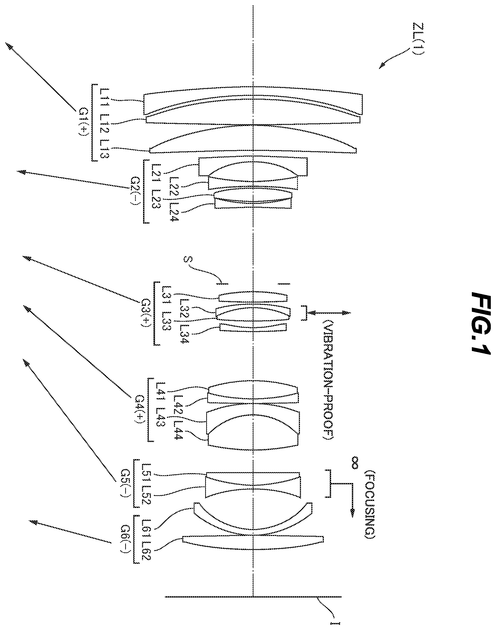
is a lens configuration diagram of a zoom optical system according to a first example upon focusing on infinity in a wide angle end state;
A and 2 B are various aberration graphs of the zoom optical system according to the first example upon focusing on infinity in the wide-angle end state and a telephoto end state;
A and 3 B are coma aberration graphs of the zoom optical system according to the first example in the wide-angle end state and the telephoto end state when blur correction is performed;
is a lens configuration diagram of a zoom optical system according to a second example upon focusing on infinity in a wide angle end state;
A and 5 B are various aberration graphs of the zoom optical system according to the second example upon focusing on infinity in the wide-angle end state and a telephoto end state;
A and 6 B are coma aberration graphs of the zoom optical system according to the second example in the wide-angle end state and the telephoto end state when blur correction is performed;
is a lens configuration diagram of a zoom optical system according to a third example upon focusing on infinity in a wide angle end state;
A and 8 B are various aberration graphs of the zoom optical system according to the third example upon focusing on infinity in the wide-angle end state and a telephoto end state;
A and 9 B are coma aberration graphs of the zoom optical system according to the third example in the wide-angle end state and the telephoto end state when blur correction is performed;
is a lens configuration diagram of a zoom optical system according to a fourth example upon focusing on infinity in a wide angle end state;
A and 11 B are various aberration graphs of the zoom optical system according to the fourth example upon focusing on infinity in the wide-angle end state and a telephoto end state;
A and 12 B are coma aberration graphs of the zoom optical system according to the fourth example in the wide-angle end state and the telephoto end state when blur correction is performed;
is a lens configuration diagram of a zoom optical system according to a fifth example upon focusing on infinity in a wide angle end state;
A and 14 B are various aberration graphs of the zoom optical system according to the fifth example upon focusing on infinity in the wide-angle end state and a telephoto end state;
A and 15 B are coma aberration graphs of the zoom optical system according to the fifth example in the wide-angle end state and the telephoto end state when blur correction is performed;
is a lens configuration diagram of a zoom optical system according to a sixth example upon focusing on infinity in a wide angle end state;
A and 17 B are various aberration graphs of the zoom optical system according to the sixth example upon focusing on infinity in the wide-angle end state and a telephoto end state;
A and 18 B are coma aberration graphs of the zoom optical system according to the sixth example in the wide-angle end state and the telephoto end state when blur correction is performed;
is a lens configuration diagram of a zoom optical system according to a seventh example upon focusing on infinity in a wide angle end state;
A and 20 B are various aberration graphs of the zoom optical system according to the seventh example upon focusing on infinity in the wide-angle end state and a telephoto end state;
A and 21 B are coma aberration graphs of the zoom optical system according to the seventh example in the wide-angle end state and the telephoto end state when blur correction is performed;
is a lens configuration diagram of a zoom optical system according to an eighth example upon focusing on infinity in a wide angle end state;
A and 23 B are various aberration graphs of the zoom optical system according to the eighth example upon focusing on infinity in the wide-angle end state and a telephoto end state;
A and 24 B are coma aberration graphs of the zoom optical system according to the eighth example in the wide-angle end state and the telephoto end state when blur correction is performed;
is a lens configuration diagram of a zoom optical system according to a ninth example upon focusing on infinity in a wide angle end state;
A and 26 B are various aberration graphs of the zoom optical system according to the ninth example upon focusing on infinity in the wide-angle end state and a telephoto end state;
A and 27 B are coma aberration graphs of the zoom optical system according to the ninth example in the wide-angle end state and the telephoto end state when blur correction is performed;
is a lens configuration diagram of a zoom optical system according to a tenth example upon focusing on infinity in a wide angle end state;
A and 29 B are various aberration graphs of the zoom optical system according to the tenth example upon focusing on infinity in the wide-angle end state and a telephoto end state;
A and 30 B are coma aberration graphs of the zoom optical system according to the tenth example in the wide-angle end state and the telephoto end state when blur correction is performed;
is a lens configuration diagram of a zoom optical system according to an eleventh example upon focusing on infinity in a wide angle end state;
A and 32 B are various aberration graphs of the zoom optical system according to the eleventh example upon focusing on infinity in the wide-angle end state and a telephoto end state;
A and 33 B are coma aberration graphs of the zoom optical system according to the eleventh example in the wide-angle end state and the telephoto end state when blur correction is performed;
is a lens configuration diagram of a zoom optical system according to a twelfth example upon focusing on infinity in a wide angle end state;
A and 35 B are various aberration graphs of the zoom optical system according to the twelfth example upon focusing on infinity in the wide-angle end state and a telephoto end state;
A and 36 B are coma aberration graphs of the zoom optical system according to the twelfth example in the wide-angle end state and the telephoto end state when blur correction is performed;
is a lens configuration diagram of a zoom optical system according to a thirteenth example upon focusing on infinity in a wide angle end state;
A and 38 B are various aberration graphs of the zoom optical system according to the thirteenth example upon focusing on infinity in the wide-angle end state and a telephoto end state;
A and 39 B are coma aberration graphs of the zoom optical system according to the thirteenth example in the wide-angle end state and the telephoto end state when blur correction is performed;
shows a configuration of a camera that comprises a zoom optical system according to this embodiment; and
is a flowchart showing a method for manufacturing the zoom optical system according to this embodiment.
DESCRIPTION OF THE EMBODIMENTS
Hereinafter, a zoom optical system and an optical apparatus according to this embodiment will be described with reference to the drawings. First, a camera (optical apparatus) comprising the zoom optical system according to this embodiment is described with reference to . As shown in , the camera 1 is a digital camera that comprises the zoom optical system according to this embodiment as a photographing lens 2 . In the camera 1 , light from an object (photographic object), not shown, is collected by the photographing lens 2 , and reaches an image pickup element 3 . Accordingly, the light from the photographic object is captured by an image pickup element 3 , and is recorded as a photographic object image in a memory, not shown. A photographer can thus take an image of the photographic object through the camera 1 . Note that the camera may be a mirrorless camera, or a single-lens reflex type camera that includes a quick return mirror.
Next, the zoom optical system (photographing lens) according to this embodiment will be described. As shown in , a zoom optical system ZL( 1 ) that is an example of a zoom optical system (zoom lens) ZL according to this embodiment comprises, in order from an object: a first lens group G 1 having a positive refractive power; a second lens group G 2 having a negative refractive power; a third lens group G 3 having a positive refractive power; a fourth lens group G 4 having a positive refractive power; a fifth lens group G 5 ; and a sixth lens group G 6 . Upon zooming, a distance between the adjacent lens groups changes. Accordingly, variation in astigmatism and spherical aberration upon zooming can be suppressed.
In the configuration described above, the zoom optical system ZL according to this embodiment satisfies the following conditional expression (1). 1.000 Mv 4/ Mv 3<3.00 (1)
where Mv3: an amount of movement of the third lens group G 3 upon zooming from a wide angle end state to a telephoto end state (a sign of the amount of movement toward an object is shown as +), and
Mv4: an amount of movement of the fourth lens group G 4 upon zooming from the wide angle end state to the telephoto end state (a sign of the amount of movement toward an object is shown as +).
According to this embodiment, the zoom optical system that has a high zooming ratio and a favorable optical performance, and the optical apparatus that comprises the zoom optical system can be obtained. The zoom optical system ZL according to this embodiment may be a zoom optical system ZL( 2 ) shown in , a zoom optical system ZL( 3 ) shown in , a zoom optical system ZL( 4 ) shown in , or a zoom optical system ZL( 5 ) shown in . The zoom optical system ZL according to this embodiment may be a zoom optical system ZL( 6 ) shown in , a zoom optical system ZL( 7 ) shown in , a zoom optical system ZL( 8 ) shown in , or a zoom optical system ZL( 9 ) shown in . The zoom optical system ZL according to this embodiment may be a zoom optical system ZL( 10 ) shown in , a zoom optical system ZL( 11 ) shown in , or a zoom optical system ZL( 13 ) shown in .
The conditional expression (1) defines the ratio between the amount of movement of the third lens group G 3 and the amount of movement of the fourth lens group G 4 upon zooming from the wide angle end state to the telephoto end state. By satisfying the conditional expression (1), variation in spherical aberration and field curves upon zooming can be suppressed.
If the corresponding value of the conditional expression (1) falls below the lower limit value, it is difficult to suppress variation in field curves upon zooming. By setting the lower limit value of the conditional expression (1) to 1.05, the advantageous effects of this embodiment can be more secured. To further secure the advantageous effects of this embodiment, the lower limit value of the conditional expression (1) may be set to 1.10, 1.15, 1.18, 1.20, 1.23, 1.25, 1.28, 1.30, 1.33 and further to 1.35.
If the corresponding value of the conditional expression (1) exceeds the upper limit value, it is difficult to correct the field curves in the wide angle end state. By setting the upper limit value of the conditional expression (1) to 2.80, the advantageous effects of this embodiment can be more secured. To further secure the advantageous effects of this embodiment, the upper limit value of the conditional expression (1) may be set to 2.50, 2.30, 2.00, 1.80, 1.65, 1.62, 1.60, 1.58, 1.55, 1.53, and further to 1.50.
Preferably, the zoom optical system ZL according to this embodiment satisfies the following conditional expression (2). 0.000 Mv 2/ fw< 10.00 (2)
where Mv2: an amount of movement of the second lens group G 2 upon zooming from the wide angle end state to the telephoto end state (a sign of the amount of movement toward an object is shown as +), and
fw: a focal length of the zoom optical system ZL in the wide angle end state.
The conditional expression (2) defines the amount of movement of the second lens group G 2 upon zooming from the wide angle end state to the telephoto end state. Note that the conditional expression (2) means that the second lens group G 2 moves toward the object upon zooming from the wide angle end state to the telephoto end state. By satisfying the conditional expression (2), the spherical aberration in the telephoto end state can be favorably corrected.
If the corresponding value of the conditional expression (2) falls below the lower limit value, it is difficult to correct the spherical aberration in the telephoto end state. By setting the lower limit value of the conditional expression (2) to 0.05, the advantageous effects of this embodiment can be more secured. To further secure the advantageous effects of this embodiment, the lower limit value of the conditional expression (2) may be set to 0.08, 0.10, 0.13, 0.15, 0.18, 0.20, 0.22, and further to 0.24.
If the corresponding value of the conditional expression (2) exceeds the upper limit value, it is difficult to correct the spherical aberration in the telephoto end state. By setting the upper limit value of the conditional expression (2) to 8.00, the advantageous effects of this embodiment can be more secured. To further secure the advantageous effects of this embodiment, the upper limit value of the conditional expression (2) may be set to 5.00, 3.00, 2.50, 2.20, 2.00, 1.80, 1.50, 1.30, 1.10, 0.95, 0.90, 0.85, 0.80, 0.75, and further to 0.70.
Preferably, the zoom optical system ZL according to this embodiment satisfies the following conditional expression (3). 3.00< ft/fw< 30.00 (3)
where ft: a focal length of the zoom optical system ZL in the telephoto end state, and
fw: a focal length of the zoom optical system ZL in the wide angle end state.
The conditional expression (3) defines the zooming ratio of the zoom optical system ZL. By satisfying the conditional expression (3), the advantageous effects of this embodiment can be exerted to the maximum at a high zooming ratio. By setting the lower limit value of the conditional expression (3) to 3.30, the advantageous effects of this embodiment can be more secured. To further secure the advantageous effects of this embodiment, the lower limit value of the conditional expression (3) may be set to 3.50, 4.00, 4.50, 5.00, 6.00, and further to 7.00. By setting the upper limit value of the conditional expression (3) to 25.00, the advantageous effects of this embodiment can be more secured. To further secure the advantageous effects of this embodiment, the upper limit value of the conditional expression (3) may be set to 20.00, 15.00, 10.00, 9.00, and further to 8.00.
Preferably, the zoom optical system ZL according to this embodiment satisfies the following conditional expression (4). 35.0°<ω w< 75.0° (4)
where ωw: a half angle of view of the zoom optical system ZL in the wide angle end state.
The conditional expression (4) defines the half angle of view of the zoom optical system ZL in the wide angle end state. By satisfying the conditional expression (4), the field curves can be favorably corrected. By setting the lower limit value of the conditional expression (4) to 38.0°, the advantageous effects of this embodiment can be more secured. To further secure the advantageous effects of this embodiment, the lower limit value of the conditional expression (4) may be set to 40.0°. By setting the upper limit value of the conditional expression (4) to 70.0°, the advantageous effects of this embodiment can be more secured. To further secure the advantageous effects of this embodiment, the upper limit value of the conditional expression (4) may be set to 60.0°, 50.0°, and further to 45.0°.
Preferably, the zoom optical system ZL according to this embodiment satisfies the following conditional expression (5). 2.5°<ω t< 15.0° (5)
where ωt: a half angle of view of the zoom optical system ZL in the telephoto end state.
The conditional expression (5) defines the half angle of view of the zoom optical system ZL in the telephoto end state. By satisfying the conditional expression (5), the advantageous effects of this embodiment can be exerted to the maximum at a high zooming ratio. By setting the lower limit value of the conditional expression (5) to 4.0°, the advantageous effects of this embodiment can be more secured. To further secure the advantageous effects of this embodiment, the lower limit value of the conditional expression (5) may be set to 5.0° and further to 5.5°. By setting the upper limit value of the conditional expression (5) to 13.0°, the advantageous effects of this embodiment can be more secured. To further secure the advantageous effects of this embodiment, the upper limit value of the conditional expression (5) may be set to 12.0°, 11.0°, 10.0°, and further to 9.0°.
Preferably, the zoom optical system ZL according to this embodiment satisfies the following conditional expression (6). −0.30< fw/f 123 w< 0.60 (6)
where fw: a focal length of the zoom optical system ZL in the wide angle end state, and
f123w: a combined focal length of the first lens group G 1 , the second lens group G 2 and the third lens group G 3 in the wide angle end state.
The conditional expression (6) defines the ratio between the focal length of the zoom optical system ZL and the combined focal length of the first lens group G 1 , the second lens group G 2 and the third lens group G 3 in the wide angle end state. Note that the conditional expression (6) means that the first lens group G 1 , the second lens group G 2 and the third lens group G 3 are substantially afocal in the wide angle end state. By satisfying the conditional expression (6), the spherical aberration and field curves in the wide angle end state can be favorably corrected.
If the corresponding value of the conditional expression (6) falls below the lower limit value, it is difficult to correct the spherical aberration in the wide angle end state. By setting the lower limit value of the conditional expression (6) to −0.28, the advantageous effects of this embodiment can be more secured. To further secure the advantageous effects of this embodiment, the lower limit value of the conditional expression (6) may be set to −0.25, −0.20, −0.15, and further to −0.12.
If the corresponding value of the conditional expression (6) exceeds the upper limit value, it is difficult to correct the spherical aberration in the wide angle end state. By setting the upper limit value of the conditional expression (6) to 0.55, the advantageous effects of this embodiment can be more secured. To further secure the advantageous effects of this embodiment, the upper limit value of the conditional expression (6) may be set to 0.50, 0.45, 0.40, 0.35, 0.30, 0.25, 0.20, 0.15, 0.10, and further to 0.05.
Preferably, the zoom optical system ZL according to this embodiment satisfies the following conditional expression (7). −1.50< ft/f 123 t< 1.00 (7)
where ft: a focal length of the zoom optical system ZL in the telephoto end state, and
f123t: a combined focal length of the first lens group G 1 , the second lens group G 2 and the third lens group G 3 in the telephoto end state.
The conditional expression (7) defines the ratio between the focal length of the zoom optical system ZL and the combined focal length of the first lens group G 1 , the second lens group G 2 and the third lens group G 3 in the telephoto end state. Note that the conditional expression (7) means that the first lens group G 1 , the second lens group G 2 and the third lens group G 3 are substantially afocal in the telephoto end state. By satisfying the conditional expression (7), the spherical aberration and field curves in the telephoto end state can be favorably corrected.
If the corresponding value of the conditional expression (7) falls below the lower limit value, it is difficult to correct the spherical aberration in the telephoto end state. By setting the lower limit value of the conditional expression (7) to −1.35, the advantageous effects of this embodiment can be more secured. To further secure the advantageous effects of this embodiment, the lower limit value of the conditional expression (7) may be set to −1.00, −0.90, and further to −0.80.
If the corresponding value of the conditional expression (7) exceeds the upper limit value, it is difficult to correct the spherical aberration in the telephoto end state. By setting the upper limit value of the conditional expression (7) to 0.50, the advantageous effects of this embodiment can be more secured. To further secure the advantageous effects of this embodiment, the upper limit value of the conditional expression (7) may be set to 0.20, 0.10, −0.10, and further to −0.20.
Preferably, the zoom optical system ZL according to this embodiment satisfies the following conditional expression (8). 0.20< BFw/fw< 0.60 (8)
where BFw: a distance to an image surface from a lens surface of the zoom optical system ZL closest to an image in the wide angle end state, and
fw: a focal length of the zoom optical system ZL in the wide angle end state.
The conditional expression (8) defines the ratio between the back focus of the zoom optical system ZL and the focal length of the zoom optical system ZL in the wide angle end state. By satisfying the conditional expression (8), the field curves in the wide angle end state can be efficiently corrected.
If the corresponding value of the conditional expression (8) falls below the lower limit value, it is difficult to correct the field curves in the wide angle end state. By setting the lower limit value of the conditional expression (8) to 0.25, the advantageous effects of this embodiment can be more secured. To further secure the advantageous effects of this embodiment, the lower limit value of the conditional expression (8) may be set to 0.30, 0.35, 0.37 and further to 0.40.
If the corresponding value of the conditional expression (8) exceeds the upper limit value, correction of the field curves in the wide angle end state becomes insufficient. By setting the upper limit value of the conditional expression (8) to 0.56, the advantageous effects of this embodiment can be more secured. To further secure the advantageous effects of this embodiment, the upper limit value of the conditional expression (8) may be set to 0.54, 0.52, and further to 0.50.
Preferably, in the zoom optical system ZL according to this embodiment, upon focusing, the fifth lens group G 5 moves with respect to an image surface. Accordingly, variation in spherical aberration upon focusing can be suppressed.
Preferably, in the zoom optical system ZL according to this embodiment, the fifth lens group G 5 includes at least one positive lens, and at least one negative lens. Accordingly, variation in field curves upon focusing can be suppressed.
Preferably, the zoom optical system ZL according to this embodiment satisfies the following conditional expression (9). 1.00<(− f 5)/ fw< 16.00 (9) where f5: a focal length of the fifth lens group G 5 , and
fw: a focal length of the zoom optical system ZL in the wide angle end state.
The conditional expression (9) defines the ratio between the focal length of the fifth lens group G 5 and the focal length of the zoom optical system ZL in the wide angle end state. By satisfying the conditional expression (9), the field curves caused upon focusing can be favorably corrected.
If the corresponding value of the conditional expression (9) falls below the lower limit value, it is difficult to suppress the field curves caused upon focusing. The amount of movement of the fifth lens group G 5 upon focusing increases, which in turn increases the size of the lens barrel. By setting the lower limit value of the conditional expression (9) to 1.10, the advantageous effects of this embodiment can be more secured. To further secure the advantageous effects of this embodiment, the lower limit value of the conditional expression (9) may be set to 1.20, 1.30, 1.40, and further to 1.45.
If the corresponding value of the conditional expression (9) exceeds the upper limit value, correction of the field curves upon focusing becomes insufficient. The amount of movement of the fifth lens group G 5 upon focusing increases, which in turn increases the size of the lens barrel. By setting the upper limit value of the conditional expression (9) to 15.50, the advantageous effects of this embodiment can be more secured. To further secure the advantageous effects of this embodiment, the upper limit value of the conditional expression (9) may be set to 10.00, 8.00, 5.00, 4.00, 3.00, 2.45, 2.38, 2.33, 2.28, 2.25, and further to 2.10.
Preferably, the zoom optical system ZL according to this embodiment satisfies the following conditional expression (10). 1.000 Mv 5/ Mv 6<3.00 (10)
where Mv5: an amount of movement of the fifth lens group G 5 upon zooming from the wide angle end state to the telephoto end state (a sign of the amount of movement toward an object is shown as +), and
Mv6: an amount of movement of the sixth lens group G 6 upon zooming from the wide angle end state to the telephoto end state (a sign of the amount of movement toward an object is shown as +).
The conditional expression (10) defines the ratio between the amount of movement of the fifth lens group G 5 and the amount of movement of the sixth lens group G 6 upon zooming from the wide angle end state to the telephoto end state. By satisfying the conditional expression (10), the field curves can be favorably corrected.
If the corresponding value of the conditional expression (10) falls below the lower limit value, it is difficult to suppress the field curves caused in the fifth lens group G 5 . By setting the lower limit value of the conditional expression (10) to 1.10, the advantageous effects of this embodiment can be more secured. To further secure the advantageous effects of this embodiment, the lower limit value of the conditional expression (10) may be set to 1.20, 1.30, and further to 1.40.
If the corresponding value of the conditional expression (10) exceeds the upper limit value, it is difficult to correct the field curves in the fifth lens group G 5 . By setting the upper limit value of the conditional expression (10) to 2.50, the advantageous effects of this embodiment can be more secured. To further secure the advantageous effects of this embodiment, the upper limit value of the conditional expression (10) may be set to 2.00, 1.80, and further to 1.60.
Preferably, in the zoom optical system ZL according to this embodiment, upon zooming, the first lens group G 1 moves with respect to the image surface. Accordingly, a high zooming ratio can be achieved.
Preferably, in the zoom optical system ZL according to this embodiment, the first lens group G 1 consists of three or more lenses. Accordingly, particularly in the telephoto end state, the spherical aberration can be favorably corrected. Furthermore, a high zooming ratio can be achieved.
Preferably, the zoom optical system ZL according to this embodiment satisfies the following conditional expression (11). 0.30< Mv 1/( ft−fw )<0.80 (11)
where Mv1: an amount of movement of the first lens group G 1 upon zooming from the wide angle end state to the telephoto end state (a sign of the amount of movement toward an object is shown as +),
ft: a focal length of the zoom optical system ZL in the telephoto end state, and
fw: a focal length of the zoom optical system ZL in the wide angle end state.
The conditional expression (11) defines the amount of movement of the first lens group G 1 with respect to variation in focal length upon zooming from the wide angle end state to the telephoto end state. By satisfying the conditional expression (11), the spherical aberration and field curves in the telephoto end state can be favorably corrected.
If the corresponding value of the conditional expression (11) falls below the lower limit value, it is difficult to correct the spherical aberration in the telephoto end state. By setting the lower limit value of the conditional expression (11) to 0.32, the advantageous effects of this embodiment can be more secured. To further secure the advantageous effects of this embodiment, the lower limit value of the conditional expression (11) may be set to 0.33, 0.34, and further to 0.35.
If the corresponding value of the conditional expression (11) exceeds the upper limit value, it is difficult to correct the field curves in the telephoto end state. Furthermore, the diameter of the first lens group G 1 increases, which in turn increases the weight of the lens barrel. By setting the upper limit value of the conditional expression (11) to 0.77, the advantageous effects of this embodiment can be more secured. To further secure the advantageous effects of this embodiment, the upper limit value of the conditional expression (11) may be set to 0.70, 0.65, 0.58, 0.50, 0.45, and further to 0.40.
Preferably, in the zoom optical system ZL according to this embodiment, an air lens is provided in the sixth lens group G 6 , and the zoom optical system ZL satisfies the following conditional expression (12). 0.00<( RAr 2+ RAr 1)/( RAr 2− RAr 1)<2.00 (12)
where RAr1: a radius of curvature of an object-side lens surface of the air lens of the sixth lens group G 6 , and
RAr2: a radius of curvature of an image-side lens surface of the air lens of the sixth lens group G 6 .
The conditional expression (12) defines the shape factor of the air lens provided in the sixth lens group G 6 . By satisfying the conditional expression (12), the field curves can be favorably corrected.
If the corresponding value of the conditional expression (12) falls below the lower limit value, it is difficult to correct the field curves. By setting the lower limit value of the conditional expression (12) to 0.01, the advantageous effects of this embodiment can be more secured. To further secure the advantageous effects of this embodiment, the lower limit value of the conditional expression (12) may be set to 0.10, 0.20, 0.28, 0.30, 0.40, and further to 0.45.
If the corresponding value of the conditional expression (12) exceeds the upper limit value, it is difficult to correct the field curves. By setting the upper limit value of the conditional expression (12) to 1.90, the advantageous effects of this embodiment can be more secured. To further secure the advantageous effects of this embodiment, the upper limit value of the conditional expression (12) may be set to 1.70, 1.50, 1.20, and further to 1.00.
Preferably, in the zoom optical system ZL according to this embodiment, upon zooming, at least the first lens group G 1 , the third lens group G 3 , the fourth lens group G 4 , the fifth lens group G 5 , and the sixth lens group G 6 move with respect to an image surface. Accordingly, the variation in magnification of each lens group upon zooming can be increased. Furthermore, the aberrations occurring at the third lens group G 3 upon zooming can be corrected by the fourth lens group G 4 .
Preferably, in the zoom optical system ZL according to this embodiment, the lens groups moving upon zooming move toward the object upon zooming from the wide angle end state to the telephoto end state. Accordingly, a sufficient zooming ratio satisfying the performance of this embodiment can be secured.
Subsequently, referring to , a method of manufacturing the zoom optical system ZL according to this embodiment is generally described. First, in order from an object, a first lens group G 1 having a positive refractive power, a second lens group G 2 having a negative refractive power, a third lens group G 3 having a positive refractive power, a fourth lens group G 4 having a positive refractive power, a fifth lens group G 5 , and a sixth lens group G 6 , are arranged (step ST 1 ). It is configured such that the distance between the adjacent lens groups changes upon zooming (step ST 2 ). Each lens is arranged in a lens barrel so as to satisfy at least the conditional expression (1) described above (step ST 3 ). According to such a manufacturing method, the zoom optical system that has a high zooming ratio and a favorable optical performance can be manufactured.
EXAMPLES
Hereinafter, zoom optical systems ZL according to examples of this embodiment will be described with reference to the drawings. , 4 , 7 , 10 , 13 , 16 , 19 , 22 , 25 , 28 , 31 , 34 and 37 are sectional views showing configurations and refractive power distributions of the zoom optical systems ZL {ZL( 1 ) to ZL( 13 )} according to first to thirteenth examples. The first to the eleventh examples and the thirteenth example are those of present inventions. The twelfth example is a reference example. In each diagram, the movement direction along the optical axis of each lens group that moves upon zooming from the wide angle end state to the telephoto end state is indicated by an arrow. Furthermore, the movement direction of a focusing group upon focusing from the infinity to a short distant object is indicated by an arrow accompanied by characters “FOCUSING”. At least a part of the third lens group G 3 is assumed as a vibration-proof group. The movement direction upon image blur correction is indicated by an arrow accompanied by characters “VIBRATION-PROOF”.
In these drawings ( , 4 , 7 , 10 , 13 , 16 , 19 , 22 , 25 , 28 , 31 , 34 and 37 ), each lens group is represented by a combination of a symbol G and a numeral, and each lens is represented by a combination of a symbol L and a numeral. In this case, to prevent the number of types and the numbers of symbols and numerals from being large and complicated, the lens groups and the like are represented using combinations of symbols and numerals independently among the examples. Accordingly, even though the same combinations of symbols and numerals are used among the examples, such usage does not mean the same configuration.
Tables 1 to 13 are hereinafter shown. Among them, Table 1 is a table showing each data item in the first example, Table 2 is that in the second example, Table 3 is that in the third example, Table 4 is that in the fourth example, Table 5 is that in the fifth example, Table 6 is that in the sixth example, Table 7 is that in the seventh example, Table 8 is that in the eighth example, Table 9 is that in the ninth example, Table 10 is that in the tenth example, Table 11 is that in the eleventh example, Table 12 is that in the twelfth example, and Table 13 is that in the thirteenth example. In each example, d-line (wavelength λ=587.6 nm), and g-line (wavelength λ=435.8 nm) are selected as calculation targets of aberration characteristics.
In tables of [General data], FNO indicates the F-number, ω indicates the half angle of view (the unit is ° (degrees)), and Y indicates the image height. TL indicates a distance obtained by adding BF to the distance from the lens foremost surface to the lens last surface on the optical axis upon focusing on infinity. BF indicates the air equivalent distance (back focus) from the lens last surface to the image surface I on the optical axis upon focusing on infinity. Note that these values are indicated for zoom states at the wide-angle end (W), a first intermediate focal length (M1), a second intermediate focal length (M2), and the telephoto end (T). f123w indicates the combined focal length of the first lens group G 1 , the second lens group G 2 and the third lens group G 3 in the wide angle end state. f123t indicates the combined focal length of the first lens group G 1 , the second lens group G 2 and the third lens group G 3 in the telephoto end state.
In the table of [Lens data], Surface number indicates the order of the optical surface from the object side along the direction in which the ray travels, R indicates the radius of curvature (the surface whose center of curvature resides on the image side is regarded to have a positive value) of each optical surface, D indicates the surface distance from each optical surface to the next optical surface (or the image surface) on the optical axis, nd is the refractive index of the material of the optical member for d-line, and νd indicates the Abbe number of the material of the optical member with reference to d-line. The radius of curvature “∞” indicates a plane or an aperture, and (Aperture stop S) indicates an aperture stop. The description of the air refractive index nd=1.00000 is omitted. In a case where the lens surface is an aspherical surface, the surface number is assigned * symbol, and the field of the radius of curvature R indicates the paraxial radius of curvature.
In the table of [Aspherical surface data], the shape of the aspherical surface indicated in [Lens data] is indicated by the following expression W. X(y) indicates the distance (sag amount) from the tangent plane at the vertex of the aspherical surface to the position on the aspherical surface at the height y along the optical axis direction. R indicates the radius of curvature (paraxial radius of curvature) of the reference spherical surface. κ indicates the conic constant. Ai indicates the i-order aspherical coefficient. “E-n” indicates “×10 −n ”. For example, 1.234E-05=1.234×10 −5 . Note that the second-order aspherical coefficient A2 is zero, and its description is omitted. X ( y )=( y 2 /R )/{1+(1−κ× y 2 /R 2 ) 1/2 }+A 4× y 4 +A 6× y 6 +A 8× y 8 +A 10× y 10 +A 12× y 12 (A)
The table of [Lens group data] shows the first surface (the surface closest to the object) and the focal length of each lens group.
The table of [Variable distance data] shows the surface distances at surface numbers where the surface distance is “Variable” in the table showing [Lens data]. Here, surface distances in the zoom states at the wide-angle end (W), the first intermediate focal length (M1), the second intermediate focal length (M2) and the telephoto end (T) upon the infinity focus and the short range focus are indicated. In [Variable distance data], f indicates the focal length of the entire lens system, and β indicates the photographing magnification.
The table of [Conditional expression corresponding value] shows the value corresponding to each conditional expression.
Hereinafter, among all the data values, “mm” is generally used for the listed focal length f, radius of curvature R, surface distance D, other lengths and the like if not otherwise specified. However, there is no limitation thereto, because the optical system can achieve equivalent optical performances even if being proportionally enlarged or reduced.
The description of the table so far is common to all the examples. Hereinafter, redundant description is omitted.
First Example
A first example is described with reference to to 3 A and 3 B and Table 1. is a lens configuration diagram of a zoom optical system according to the first example upon focusing on infinity in a wide angle end state. The zoom optical system ZL( 1 ) according to the first example consists of, in order from the object: a first lens group G 1 having a positive refractive power; a second lens group G 2 having a negative refractive power; an aperture stop S; a third lens group G 3 having a positive refractive power; a fourth lens group G 4 having a positive refractive power; a fifth lens group G 5 having a negative refractive power; and a sixth lens group G 6 having a negative refractive power. Upon zooming from the wide angle end state to the telephoto end state, the first lens group G 1 , the second lens group G 2 , the aperture stop S, the third lens group G 3 , the fourth lens group G 4 , the fifth lens group G 5 and the sixth lens group G 6 move in the directions indicated by arrows in along the optical axis, and the distances between the adjacent lens groups change. Note that upon zooming, the aperture stop S, the third lens group G 3 and the sixth lens group G 6 integrally move. The sign (+) or (−) assigned to each lens group symbol indicates the refractive power of the corresponding lens group. This similarly applies to all the following examples.
The first lens group G 1 consists of, in order from the object: a negative meniscus lens L 11 having a convex surface facing the object; a biconvex positive lens L 12 ; and a positive meniscus lens L 13 having a convex surface facing the object.
The second lens group G 2 consists of, in order from the object: a negative meniscus lens L 21 having a convex surface facing the object; a biconcave negative lens L 22 ; a biconvex positive lens L 23 ; and a biconcave negative lens L 24 .
The third lens group G 3 consists of, in order from the object: a biconvex positive lens L 31 ; a cemented lens composed of a negative meniscus lens L 32 having a convex surface facing the object and a biconvex positive lens L 33 ; and a negative meniscus lens L 34 having a concave surface facing the object.
The fourth lens group G 4 consists of, in order from the object: a cemented lens composed of a biconvex positive lens L 41 and a negative meniscus lens L 42 having a concave surface facing the object; and a cemented lens composed of a negative meniscus lens L 43 having a convex surface facing the object and a biconvex positive lens L 44 . The image side surface of the positive lens L 44 is of aspherical shape.
The fifth lens group G 5 consists of a cemented lens composed of a biconvex positive lens L 51 and a biconcave negative lens L 52 . The image side surface of the negative lens L 52 is of aspherical shape.
The sixth lens group G 6 consists of, in order from the object: a negative meniscus lens L 61 having a concave surface facing the object; and a biconvex positive lens L 62 . An air lens is formed between the negative meniscus lens L 61 and the positive lens L 62 . The image side surface of the negative meniscus lens L 61 is of aspherical shape. The image surface I is disposed on the image side of the sixth lens group G 6 .
In this example, by moving the fifth lens group G 5 toward the image surface I, focusing from a far distant object to a short distant object (from an infinity object to a finite distance object) is achieved. In this example, the cemented lens composed of the negative meniscus lens L 32 and the positive lens L 33 in the third lens group G 3 constitutes a vibration-proof group that has a positive refractive power and is movable in a direction perpendicular to the optical axis, and corrects the displacement of the imaging position due to camera shake and the like (an image blur on the image surface I).
The following Table 1 lists values of data on the zoom optical system according to the first example.
TABLE 1
[General Data]
Zooming ratio 7.848
f123w = −217.63848
f123t = −267.32298
W M1 M2 T
FNO 4.12109 5.58779 6.39998 6.50002
ω 42.58698 22.66696 11.13686 6.13014
Y 20.50 21.70 21.70 21.70
TL 126.45486 144.98844 168.50373 188.4741
[Lens Data]
Surface Number R D νd nd
1 185.7354 2.0000 31.27 1.903660
2 75.9813 1.0263
3 81.5981 6.4204 67.90 1.593190
4 −494.4016 0.1000
5 59.1320 6.1300 67.90 1.593190
6 390.1369 D1(Variable)
7 236.0277 1.2500 32.33 1.953750
8 19.0394 5.0675
9 −46.6700 1.1000 52.33 1.755000
10 68.1612 0.4169
11 37.1210 3.3840 20.88 1.922860
12 −52.5580 0.5124
13 −32.9357 1.0000 46.59 1.816000
14 416.8076 D2(Variable)
15 ∞ 2.0000 (Aperture
Stop S)
16 39.8204 2.5136 35.72 1.902650
17 −292.5261 0.5000
18 36.7161 1.0000 29.12 2.001000
19 20.9452 3.3404 53.74 1.579570
20 −76.0620 1.4447
21 −35.5626 1.0000 32.33 1.953750
22 −290.1606 D3(Variable)
23 37.1374 4.6344 42.73 1.834810
24 −37.1374 1.0000 31.27 1.903660
25 −308.9768 0.1000
26 31.6449 2.7756 32.33 1.953750
27 15.2741 8.7030 81.49 1.497100
28* −40.3095 D4(Variable)
29 1365.4927 3.0634 23.80 1.846660
30 −35.3251 1.0000 40.13 1.851350
31* 32.6144 D5(Variable)
32 −16.9998 1.4000 42.51 1.820800
33* −22.5398 0.1000
34 626.7496 3.5530 37.57 1.683760
35 −77.6296 BF
[Aspherical Surface Data]
28th Surface
κ = 1.0000, A4 = 3.13017E−05, A6 = −1.03090E−07
A8 = 6.53525E−10, A10 = −2.57830E−12, A12 = 0.32673E−14
31st Surface
κ = 1.0000, A4 = −6.66636E−06, A6 = 5.10546E−08
A8 = 1.72567E−11, A10 = −2.40595E−12, A12 = 0.98445E−14
33rd Surface
κ = 1.0000, A4 = −1.93366E−06, A6 = −2.05750E−08
A8 = 8.81224E−11, A10 = −2.94021E−13, A12 = 0.00000E+00
[Lens Group Data]
Group First surface Focal length
G1 1 98.9899
G2 7 −16.5057
G3 16 48.48369
G4 23 28.91747
G5 29 −39.0895
G6 32 −15588.34
[Variable Distance Data]
W M1 M2 T
Infinity Infinity Infinity Infinity
f 24.72001 49.99999 105.05133 193.99063
D0 ∞ ∞ ∞ ∞
D1 1.50000 17.29645 38.92328 54.52847
D2 18.83905 10.91446 4.55495 1.10018
D3 12.23175 6.39417 3.18615 1.47844
D4 5.54311 4.42699 5.70823 2.00068
D5 10.05055 17.00460 18.93085 24.34574
BF 11.75486 22.41624 30.66474 38.48515
W M1 M2 T
Short- Short- Short- Short-
distance distance distance distance
β −0.06221 −0.11053 −0.17918 −0.28386
D0 365.9340 397.4004 473.8851 503.9147
D1 1.50000 17.29645 38.92328 54.52847
D2 18.83905 10.91446 4.55495 1.10018
D3 12.23175 6.39417 3.18615 1.47844
D4 6.43705 6.05192 10.02051 11.69839
D5 9.15661 15.37967 14.61857 14.64803
BF 11.78171 22.50112 30.88824 39.04500
[Conditional expression corresponding value]
Conditional Expression(1) Mv4/Mv3 = 1.402
Conditional Expression(2) Mv2/fw = 0.364
Conditional Expression(3) ft/fw = 7.848
Conditional Expression(4) ωw = 42.587
Conditional Expression(5) ωt = 6.130
Conditional Expression(6) fw/f123w = −0.114
Conditional Expression(7) ft/f123t = −0.726
Conditional Expression(8) BFw/fw = 0.476
Conditional Expression(9) (−f5)/fw = 1.581
Conditional Expression(10) Mv5/Mv6 = 1.535
Conditional Expression(11) Mv1/(ft − fw) = 0.366
Conditional Expression(12) (RAr2 + RAr1)/(RAr2 − RAr1) = 0.931
A and 2 B are various aberration graphs of the zoom optical system according to the first example upon focusing on infinity in the wide-angle end state and the telephoto end state. A and 3 B are coma aberration graphs of the zoom optical system according to the first example in the wide-angle end state and the telephoto end state when blur correction is performed. In the aberration graphs in A and 2 B , FNO indicates the F-number, and Y indicates the image height. The spherical aberration graph indicates the value of the F-number corresponding to the maximum diameter. The astigmatism graph and the distortion graph each indicate the maximum value of the image height. The coma aberration graph indicates the value of each image height. The coma aberration graphs in A and 3 B indicate the value of each image height. In each aberration graph, d indicates d-line (wavelength)=587.6 nm), and g indicates g-line (wavelength λ=435.8 nm). In the astigmatism graph, a solid line indicates a sagittal image surface, and a broken line indicates a meridional image surface. Note that also in the aberration graph in each example described below, symbols similar to those in this example are used, and redundant description is omitted.
The various aberration graphs show that the zoom optical system according to the first example favorably corrects the various aberrations, and has an excellent imaging performance.
Second Example
A second example is described with reference to to 6 A and 6 B and Table 2. is a lens configuration diagram of a zoom optical system according to the second example upon focusing on infinity in a wide angle end state. The zoom optical system ZL( 2 ) according to the second example consists of, in order from the object: a first lens group G 1 having a positive refractive power; a second lens group G 2 having a negative refractive power; a third lens group G 3 that has a positive refractive power and is provided with an aperture stop S; a fourth lens group G 4 having a positive refractive power; a fifth lens group G 5 having a negative refractive power; and a sixth lens group G 6 having a negative refractive power. Upon zooming from the wide angle end state to the telephoto end state, the first lens group G 1 , the second lens group G 2 , the third lens group G 3 provided with the aperture stop S, the fourth lens group G 4 , the fifth lens group G 5 and the sixth lens group G 6 move in the directions indicated by arrows in along the optical axis, and the distances between the adjacent lens groups change. Note that upon zooming, the aperture stop S, the third lens group G 3 and the sixth lens group G 6 integrally move.
The first lens group G 1 consists of, in order from the object: a negative meniscus lens L 11 having a convex surface facing the object; a biconvex positive lens L 12 ; and a positive meniscus lens L 13 having a convex surface facing the object.
The second lens group G 2 consists of, in order from the object: a negative meniscus lens L 21 having a convex surface facing the object; a biconcave negative lens L 22 ; a biconvex positive lens L 23 ; and a negative meniscus lens L 24 having a concave surface facing the object.
The third lens group G 3 consists of, in order from the object: a biconvex positive lens L 31 ; an aperture stop S; a cemented lens composed of a negative meniscus lens L 32 having a convex surface facing the object and a biconvex positive lens L 33 ; and a negative meniscus lens L 34 having a concave surface facing the object.
The fourth lens group G 4 consists of, in order from the object: a cemented lens composed of a biconvex positive lens L 41 , and a negative meniscus lens L 42 having a concave surface facing the object; and a cemented lens composed of a negative meniscus lens L 43 having a convex surface facing the object and a biconvex positive lens L 44 . The image side surface of the positive lens L 44 is of aspherical shape.
The fifth lens group G 5 consists of a cemented lens composed of a biconvex positive lens L 51 and a biconcave negative lens L 52 . The image side surface of the negative lens L 52 is of aspherical shape.
The sixth lens group G 6 consists of, in order from the object: a negative meniscus lens L 61 having a concave surface facing the object; and a biconvex positive lens L 62 . An air lens is formed between the negative meniscus lens L 61 and the positive lens L 62 . The image side surface of the negative meniscus lens L 61 is of aspherical shape. The image surface I is disposed on the image side of the sixth lens group G 6 .
In this example, by moving the fifth lens group G 5 toward the image surface I, focusing from a far distant object to a short distant object (from an infinity object to a finite distance object) is achieved. In this example, the cemented lens composed of the negative meniscus lens L 32 and the positive lens L 33 in the third lens group G 3 constitutes a vibration-proof group that has a positive refractive power and is movable in a direction perpendicular to the optical axis, and corrects the displacement of the imaging position due to camera shake and the like (an image blur on the image surface I).
The following Table 2 lists values of data on the zoom optical system according to the second example.
TABLE 2
[General Data]
Zooming ratio 7.848
f123w = −377.733
f123t = −288.19144
W M1 M2 T
FNO 4.12000 5.60000 6.20000 6.49999
ω 43.04718 22.53540 10.65017 6.13829
Y 20.91 21.70 21.70 21.70
TL 125.95528 142.51715 167.85323 186.8435
[Lens Data]
Surface Number R D νd nd
1 188.64525 2.00000 31.27 1.903660
2 77.80524 0.84780
3 80.41425 6.51915 67.90 1.593190
4 −471.30377 0.10000
5 62.30684 5.66572 67.90 1.593190
6 358.24871 D1(Variable)
7 230.01286 1.25000 43.79 1.848500
8 18.45421 5.50336
9 −40.33983 1.10000 52.34 1.755000
10 79.65336 0.38546
11 39.14822 3.37749 23.80 1.846660
12 −47.38891 0.46523
13 −31.94449 1.00000 46.59 1.816000
14 −2729.77760 D2(Variable)
15 41.64137 2.51154 35.73 1.902650
16 −289.39118 0.40000
17 ∞ 0.10000 (Aperture
Stop S)
18 38.12143 1.00000 29.12 2.001000
19 21.49924 3.26023 53.74 1.579570
20 −73.20919 1.47119
21 −34.94662 1.00000 32.33 1.953750
22 −165.99888 D3(Variable)
23 37.20805 4.18411 42.73 1.834810
24 −43.17368 1.00003 31.27 1.903660
25 −659.56023 1.54931
26 28.71779 1.32801 32.33 1.953750
27 14.76801 9.10325 81.49 1.497100
28* −42.86465 D4 (Variable)
29 255.99237 3.36761 23.80 1.846660
30 −33.68693 1.00000 40.13 1.851350
31* 31.06431 D5(Variable)
32 −23.57856 1.40000 45.21 1.794457
33* −50.21699 0.10000
34 91.45040 3.78568 29.84 1.800000
35 −197.78095 BF
[Aspherical Surface Data]
28th Surface
κ = 1.0000, A4 = 2.56920E−05, A6 = −9.38399E−08
A8 = 4.71077E−10, A10 = −1.70196E−12, A12 = 0.00000E+00
31st Surface
κ = 1.0000, A4 = −6.78111E−06, A6 = 6.47335E−08
A8 = −3.28125E−10, A10 = 2.56418E−13, A12 = 0.00000E+00
33rd Surface
κ = 1.0000, A4 = 3.30419E−06, A6 = −1.76274E−09
A8 = 1.66657E−12, A10 = 1.80471E−14, A12 = 0.00000E+00
[Lens Group Data]
Group First surface Focal length
G1 1 102.16195
G2 7 −16.76640
G3 15 47.83089
G4 23 29.71748
G5 29 −41.62356
G6 32 −236.16863
[Variable Distance Data]
W M1 M2 T
Infinity Infinity Infinity Infinity
f 24.72031 50.00094 110.00281 194.00483
D0 ∞ ∞ ∞ ∞
D1 1.50000 17.23398 38.86323 55.71214
D2 19.13452 10.77832 3.90279 1.10000
D3 12.16022 5.90688 2.59619 1.47832
D4 5.12094 4.32200 5.90770 2.00000
D5 10.00915 17.06861 18.78383 23.80987
BF 11.25528 20.43218 31.02431 35.96804
W M1 M2 T
Short- Short- Short- Short-
distance distance distance distance
β −0.06086 −0.10794 −0.18504 −0.27368
D0 374.0451 407.4838 482.1484 513.1582
D1 1.50000 17.23398 38.86323 55.71214
D2 19.13452 10.77832 3.90279 1.10000
D3 12.16022 5.90688 2.59619 1.47832
D4 6.06949 6.02341 10.42761 11.59738
D5 9.06059 15.36720 14.26392 14.21249
BF 11.25529 20.4322 31.02445 35.96847
[Conditional expression corresponding value]
Conditional Expression(1) Mv4/Mv3 = 1.432
Conditional Expression(2) Mv2/fw = 0.270
Conditional Expression(3) ft/fw = 7.848
Conditional Expression(4) ωw = 43.047
Conditional Expression(5) ωt = 6.138
Conditional Expression(6) fw/f123w = −0.112
Conditional Expression(7) ft/f123t = −0.783
Conditional Expression(8) BFw/fw = 0.455
Conditional Expression(9) (−f5)/fw = 1.684
Conditional Expression(10) Mv5/Mv6 = 1.558
Conditional Expression(11) Mv1/(ft − fw) = 0.360
Conditional Expression(12) (RAr2 + RAr1)/(RAr2 − RAr1) = 0.291
A and 5 B are various aberration graphs of the zoom optical system according to the second example upon focusing on infinity in the wide-angle end state and the telephoto end state. A and 6 B are coma aberration graphs of the zoom optical system according to the second example in the wide-angle end state and the telephoto end state when blur correction is performed. The various aberration graphs show that the zoom optical system according to the second example favorably corrects the various aberrations, and has an excellent imaging performance.
Third Example
A third example is described with reference to to 9 A and 9 B and Table 3. is a lens configuration diagram of a zoom optical system according to the third example upon focusing on infinity in a wide angle end state. The zoom optical system ZL( 3 ) according to the third example consists of, in order from the object: a first lens group G 1 having a positive refractive power; a second lens group G 2 having a negative refractive power; an aperture stop S; a third lens group G 3 having a positive refractive power; a fourth lens group G 4 having a positive refractive power; a fifth lens group G 5 having a negative refractive power; and a sixth lens group G 6 having a negative refractive power. Upon zooming from the wide angle end state to the telephoto end state, the first lens group G 1 , the second lens group G 2 , the aperture stop S, the third lens group G 3 , the fourth lens group G 4 , the fifth lens group G 5 and the sixth lens group G 6 move in the directions indicated by arrows in along the optical axis, and the distances between the adjacent lens groups change. Note that upon zooming, the aperture stop S, the third lens group G 3 and the sixth lens group G 6 integrally move.
The first lens group G 1 consists of, in order from the object: a cemented lens composed of a negative meniscus lens L 11 having a convex surface facing the object and a biconvex positive lens L 12 ; and a positive meniscus lens L 13 having a convex surface facing the object.
The second lens group G 2 consists of, in order from the object: a negative meniscus lens L 21 having a convex surface facing the object; a negative meniscus lens L 22 having a convex surface facing the object; a positive meniscus lens L 23 having a convex surface facing the object; and a cemented lens composed of a positive meniscus lens L 24 having a concave surface facing the object and a negative meniscus lens L 25 having a concave surface facing the object. The image side surface of the negative meniscus lens L 21 is of aspherical shape. The image side surface of the negative meniscus lens L 25 is of aspherical shape.
The third lens group G 3 consists of a positive meniscus lens L 31 having a convex surface facing the object. The image side surface of the positive meniscus lens L 31 is of aspherical shape.
The fourth lens group G 4 consists of, in order from the object: a biconvex positive lens L 41 ; a cemented lens composed of a negative meniscus lens L 42 having a convex surface facing the object and a positive meniscus lens L 43 having a convex surface facing the object; and a cemented lens composed of a biconvex positive lens L 44 and a negative meniscus lens L 45 having a concave surface facing the object. The image side surface of the negative meniscus lens L 45 is of aspherical shape.
The fifth lens group G 5 consists of a cemented lens composed of a positive meniscus lens L 51 having a concave surface facing the object and a biconcave negative lens L 52 . The image side surface of the negative lens L 52 is of aspherical shape.
The sixth lens group G 6 consists of, in order from the object: a negative meniscus lens L 61 having a concave surface facing the object; and a positive meniscus lens L 62 having a concave surface facing the object. An air lens is formed between the negative meniscus lens L 61 and the positive meniscus lens L 62 . The image surface I is disposed on the image side of the sixth lens group G 6 .
In this example, by moving the fifth lens group G 5 toward the image surface I, focusing from a far distant object to a short distant object (from an infinity object to a finite distance object) is achieved. In this example, the positive meniscus lens L 31 in the third lens group G 3 constitutes a vibration-proof group that has a positive refractive power and is movable in a direction perpendicular to the optical axis, and corrects the displacement of the imaging position due to camera shake and the like (an image blur on the image surface I).
The following Table 3 lists values of data on the zoom optical system according to the third example.
TABLE 3
[General Data]
Zooming ratio 7.850
f123w = −526.69259
f123t = −297.45559
W M1 M2 T
FNO 4.12000 5.00001 6.14000 6.50003
ω 41.94830 22.05780 10.36801 5.96172
Y 21.34 21.70 21.70 21.70
TL 118.25612 134.48400 163.70742 182.4804
[Lens Data]
Surface Number R D νd nd
1 151.3952 2.0000 23.80 1.846660
2 87.2806 5.9280 67.90 1.593190
3 −1349.8590 0.1000
4 76.7487 4.4238 67.90 1.593190
5 320.3570 D1(Variable)
6* 395.1403 1.2500 40.66 1.883000
7 17.9444 4.0881
8 172.0131 1.0000 27.15 1.944421
9 41.2622 0.6317
10 28.0910 3.7608 20.88 1.922860
11 282.0417 1.6588
12 −43.9082 1.6452 25.64 1.784720
13 −19.4929 1.1000 43.36 1.839318
14* −367.3130 D2(Variable)
15 ∞ 1.8230 (Aperture
Stop S)
16* 25.2025 2.7754 59.33 1.609605
17 116.8971 D3(Variable)
18 27.7315 3.2255 67.90 1.593190
19 −829.3049 0.7234
20 31.9256 2.0849 32.32 1.953747
21 14.4283 4.6386 70.32 1.487490
22 87.2035 0.7730
23 61.3969 5.2420 82.57 1.497820
24 −18.0219 4.1197 37.22 1.882023
25* −25.6911 D4(Variable)
26 −1678.9249 3.0141 25.26 1.902000
27 −33.6869 1.0000 40.12 1.851080
28* 40.9152 D5(Variable)
29 −15.4450 1.2500 46.59 1.816000
30 −29.1017 0.1000
31 −162.7939 2.9649 29.37 1.950000
32 −61.0034 BF
[Aspherical Surface Data]
6th Surface
κ = 1.9193, A4 = 5.26888E−06, A6 = −1.61582E−08
A8 = 5.37910E−11, A10 = −9.15512E−14, A12 = 0.00000E+00
14th Surface
κ = 6.0000, A4 = 8.64764E−07, A6 = −1.04249E−08
A8 = −8.45595E−12, A10 = 4.36832E−13, A12 = 0.00000E+00
16th Surface
κ = −0.0411, A4 = −5.82687E−06, A6 = 1.89727E−08
A8 = −3.04157E−10, A10 = 1.94188E−12, A12 = 0.00000E+00
25th Surface
κ = 1.0633, A4 = 1.55522E−05, A6 = −4.60661E−08
A8 = 2.01166E−10, A10 = −8.69226E−13, A12 = 0.00000E+00
28th Surface
κ = 0.0000, A4 = −8.62706E−06, A6 = 9.53672E−08
A8 = −5.21848E−10, A10 = 1.74761E−12, A12 = 0.00000E+00
[Lens Group Data]
Group First surface Focal length
G1 1 111.43064
G2 6 −17.83112
G3 16 52.10796
G4 18 30.96133
G5 26 −50.42308
G6 29 −77.20586
[Variable Distance Data]
W M1 M2 T
Infinity Infinity Infinity Infinity
f 24.72028 50.00010 110.02145 194.04302
D0 ∞ ∞ ∞ ∞
D1 1.56355 16.96393 42.92481 58.95782
D2 18.90672 9.77960 3.82294 0.50000
D3 10.22026 5.92276 2.94135 1.20000
D4 6.49920 5.70254 5.42574 2.50000
D5 10.45535 15.54950 18.80771 23.47480
BF 9.29011 19.24474 28.46394 34.52694
W M1 M2 T
Short- Short- Short- Short-
distance distance distance distance
β −0.06124 −0.12203 −0.24452 −0.38142
D0 373.1327 356.9049 327.6814 308.9084
D1 1.56355 16.96393 42.92481 58.95782
D2 18.90672 9.77960 3.82294 0.50000
D3 10.22026 5.92276 2.94135 1.20000
D4 7.63429 7.89257 11.92314 16.79614
D5 9.32026 13.35947 12.31031 9.17866
BF 9.31670 19.34984 28.88441 35.54307
[Conditional expression corresponding value]
Conditional Expression(1) Mv4/Mv3 = 1.357
Conditional Expression(2) Mv2/fw = 0.276
Conditional Expression(3) ft/fw = 7.850
Conditional Expression(4) ωw = 41.948
Conditional Expression(5) ωt = 5.962
Conditional Expression(6) fw/f123w = −0.047
Conditional Expression(7) ft/f123t = −0.652
Conditional Expression(8) BFw/fw = 0.376
Conditional Expression(9) (−f5)/fw = 2.040
Conditional Expression(10) Mv5/Mv6 = 1.516
Conditional Expression(11) Mv1/(ft − fw) = 0.379
Conditional Expression(12) (RAr2 + RAr1)/(RAr2 − RAr1) = 1.435
A and 8 B are various aberration graphs of the zoom optical system according to the third example upon focusing on infinity in the wide-angle end state and the telephoto end state. A and 9 B are coma aberration graphs of the zoom optical system according to the third example in the wide-angle end state and the telephoto end state when blur correction is performed. The various aberration graphs show that the zoom optical system according to the third example favorably corrects the various aberrations, and has an excellent imaging performance.
Fourth Example
A fourth example is described with reference to to 12 A and 12 B and Table 4. is a lens configuration diagram of a zoom optical system according to the fourth example upon focusing on infinity in a wide angle end state. The zoom optical system ZL( 4 ) according to the fourth example consists of, in order from the object: a first lens group G 1 having a positive refractive power; a second lens group G 2 having a negative refractive power; an aperture stop S; a third lens group G 3 having a positive refractive power; a fourth lens group G 4 having a positive refractive power; a fifth lens group G 5 having a negative refractive power; and a sixth lens group G 6 having a negative refractive power. Upon zooming from the wide angle end state to the telephoto end state, the first lens group G 1 , the second lens group G 2 , the aperture stop S, the third lens group G 3 , the fourth lens group G 4 , the fifth lens group G 5 and the sixth lens group G 6 move in directions indicated by arrows in along the optical axis, and the distances between the adjacent lens groups change. Note that upon zooming, the aperture stop S, the third lens group G 3 and the sixth lens group G 6 integrally move.
The first lens group G 1 consists of, in order from the object: a cemented lens composed of a negative meniscus lens L 11 having a convex surface facing the object and a biconvex positive lens L 12 ; and a positive meniscus lens L 13 having a convex surface facing the object.
The second lens group G 2 consists of, in order from the object: a negative meniscus lens L 21 having a convex surface facing the object; a negative meniscus lens L 22 having a convex surface facing the object; a biconvex positive lens L 23 ; a cemented lens composed of a positive meniscus lens L 24 having a concave surface facing the object and a negative meniscus lens L 25 having a concave surface facing the object. The object side surface of the negative meniscus lens L 21 is of aspherical shape. The image side surface of the negative meniscus lens L 25 is of aspherical shape.
The third lens group G 3 consists of, in order from the object: a positive meniscus lens L 31 having a convex surface facing the object; and a cemented lens composed of a biconvex positive lens L 32 and a negative meniscus lens L 33 having a concave surface facing the object. The image side surface of the positive meniscus lens L 31 is of aspherical shape.
The fourth lens group G 4 consists of, in order from the object: a positive meniscus lens L 41 having a convex surface facing the object; a cemented lens composed of a negative meniscus lens L 42 having a convex surface facing the object and a positive meniscus lens L 43 having a convex surface facing the object; and a cemented lens composed of a positive meniscus lens L 44 having a concave surface facing the object and a negative meniscus lens L 45 having a concave surface facing the object. The image side surface of the negative meniscus lens L 45 is of aspherical shape.
The fifth lens group G 5 consists of a cemented lens composed of a biconvex positive lens L 51 and a biconcave negative lens L 52 . The image side surface of the negative lens L 52 is of aspherical shape.
The sixth lens group G 6 consists of, in order from the object: a negative meniscus lens L 61 having a concave surface facing the object; and a plano-convex positive lens L 62 having a plane facing the image surface I. An air lens is formed between the negative meniscus lens L 61 and the positive lens L 62 . The image surface I is disposed on the image side of the sixth lens group G 6 .
In this example, by moving the fifth lens group G 5 toward the image surface I, focusing from a far distant object to a short distant object (from an infinity object to a finite distance object) is achieved. In this example, the cemented lens composed of the positive lens L 32 and the negative meniscus lens L 33 in the third lens group G 3 constitutes a vibration-proof group that has a positive refractive power and is movable in a direction perpendicular to the optical axis, and corrects the displacement of the imaging position due to camera shake and the like (an image blur on the image surface I).
The following Table 4 lists values of data on the zoom optical system according to the fourth example.
TABLE 4
[General Data]
Zooming ratio 7.848
f123w = 102.18699
f123t = −1535.17561
W M1 M2 T
FNO 4.12000 5.00001 6.14000 6.50003
ω 41.94830 22.05780 10.36801 5.96172
Y 21.65 21.70 21.70 21.70
TL 122.11284 138.25648 173.12226 195.4602
[Lens Data]
Surface Number R D νd nd
1 157.9423 2.0000 23.80 1.846660
2 81.8879 5.9036 67.90 1.593190
3 −2013.3747 0.1000
4 63.5017 4.6636 63.34 1.618000
5 210.8809 D1(Variable)
6* 318.1018 1.2500 40.66 1.883000
7 16.7008 4.7201
8 704.9777 1.3500 25.79 1.940573
9 35.9277 0.1354
10 25.6246 4.3288 20.88 1.922860
11 −84.8316 1.1878
12 −26.8353 2.5514 26.72 1.759928
13 −14.0619 1.1000 40.66 1.883000
14* −120.1155 D2(Variable)
15 ∞ 1.7168 (Aperture
Stop S)
16* 25.0707 2.5492 56.42 1.650119
17 50.5707 1.8201
18 2141.2793 3.9646 47.10 1.718816
19 −19.4561 1.2000 29.37 1.950000
20 −40.3974 D3(Variable)
21 33.1155 2.7430 58.12 1.622989
22 102.1338 0.1000
23 26.3197 4.3495 29.37 1.950000
24 14.1783 4.4212 70.32 1.487490
25 72.5822 1.6811
26 −306.2709 4.3812 82.57 1.497820
27 −18.7373 1.2500 37.22 1.882023
28* −24.4766 D4 (Variable)
29 119.2349 3.5589 25.92 1.805628
30 −33.6869 1.0000 40.12 1.851080
31* 32.8619 D5 (Variable)
32 −22.4629 1.2500 40.66 1.883000
33 −43.8572 0.1000
34 61.5070 4.1976 33.02 1.689260
35 ∞ BF
[Aspherical Surface Data]
6th Surface
κ = 6.0000, A4 = 9.24936E−06, A6 = 4.48621E−09
A8 = −4.48203E−11, A10 = 1.65001E−13, A12 = 0.00000E+00
14th Surface
κ = 5.8635, A4 = −1.80704E−06, A6 = 1.46957E−08
A8 = −7.35664E−11, A10 = −5.50824E−13, A12 = 0.00000E+00
16th Surface
κ = 0.0729, A4 = −4.52720E−06, A6 = 2.52623E−08
A8 = −1.11420E−10, A10 = 1.41519E−13, A12 = 0.00000E+00
28th Surface
κ = 1.0568, A4 = 1.62692E−05, A6 = −9.59061E−09
A8 = −6.35322E−11, A10 = 1.73247E−13, A12 = 0.00000E+00
31st Surface
κ = 1.0365, A4 = −5.49985E−06, A6 = 5.29125E−08
A8 = −9.39998E−11, A10 = 1.17057E−13, A12 = 0.00000E+00
[Lens Group Data]
Group First surface Focal length
G1 1 106.62052
G2 6 −16.22739
G3 16 41.04090
G4 21 40.60874
G5 29 −49.86905
G6 32 −140.23760
[Variable Distance Data]
W M1 M2 T
Infinity Infinity Infinity Infinity
f 24.71999 49.99999 109.99995 193.99988
D0 ∞ ∞ ∞ ∞
D1 1.50000 18.53350 35.68354 55.45436
D2 17.47125 8.41504 3.49296 0.78316
D3 8.24386 2.43196 1.40000 1.44036
D4 6.00186 7.14502 5.60349 2.49999
D5 10.03309 14.70182 17.27531 20.33845
BF 9.28884 17.45519 40.09303 45.36996
W M1 M2 T
Short- Short- Short- Short-
distance distance distance distance
β −0.06195 −0.10885 −0.20280 −0.28444
D0 369.2759 403.0933 448.2665 495.9287
D1 1.50000 18.53350 35.68354 55.45436
D2 17.47125 8.41504 3.49296 0.78316
D3 8.24386 2.43196 1.40000 1.44036
D4 7.29302 9.64626 10.19294 12.30143
D5 8.74193 12.20058 12.68586 10.53701
BF 9.31603 17.53910 40.38407 45.94189
[Conditional expression corresponding value]
Conditional Expression(1) Mv4/Mv3 = 1.189
Conditional Expression(2) Mv2/fw = 0.785
Conditional Expression(3) ft/fw = 7.848
Conditional Expression(4) ωw = 41.948
Conditional Expression(5) ωt = 5.962
Conditional Expression(6) fw/f123w = 0.242
Conditional Expression(7) ft/f123t = −0.126
Conditional Expression(8) BFw/fw = 0.376
Conditional Expression(9) (−f5)/fw = 2.017
Conditional Expression(10) Mv5/Mv6 = 1.286
Conditional Expression(11) Mv1/(ft − fw) = 0.433
Conditional Expression(12) (RAr2 + RAr1)/(RAr2 − RAr1) = 0.168
A and 11 B are various aberration graphs of the zoom optical system according to the fourth example upon focusing on infinity in the wide-angle end state and the telephoto end state. A and 12 B are coma aberration graphs of the zoom optical system according to the fourth example in the wide-angle end state and the telephoto end state when blur correction is performed. The various aberration graphs show that the zoom optical system according to the fourth example favorably corrects the various aberrations, and has an excellent imaging performance.
Fifth Example
A fifth example is described with reference to to 15 A and 15 B and Table 5. is a lens configuration diagram of a zoom optical system according to the fifth example upon focusing on infinity in a wide angle end state. The zoom optical system ZL( 5 ) according to the fifth example consists of, in order from the object: a first lens group G 1 having a positive refractive power; a second lens group G 2 having a negative refractive power; an aperture stop S; a third lens group G 3 having a positive refractive power; a fourth lens group G 4 having a positive refractive power; a fifth lens group G 5 having a negative refractive power; and a sixth lens group G 6 having a positive refractive power. Upon zooming from the wide angle end state to the telephoto end state, the first lens group G 1 , the second lens group G 2 , the aperture stop S, the third lens group G 3 , the fourth lens group G 4 , the fifth lens group G 5 and the sixth lens group G 6 move in directions indicated by arrows in along the optical axis, and the distances between the adjacent lens groups change. Note that upon zooming, the aperture stop S, the third lens group G 3 and the sixth lens group G 6 integrally move.
The first lens group G 1 consists of, in order from the object: a cemented lens composed of a negative meniscus lens L 11 having a convex surface facing the object and a biconvex positive lens L 12 ; and a positive meniscus lens L 13 having a convex surface facing the object.
The second lens group G 2 consists of, in order from the object: a negative meniscus lens L 21 having a convex surface facing the object; a biconcave negative lens L 22 ; a biconvex positive lens L 23 ; and a negative meniscus lens L 24 having a concave surface facing the object. The object side surface of the negative meniscus lens L 21 is of aspherical shape. The image side surface of the negative meniscus lens L 24 is of aspherical shape.
The third lens group G 3 consists of, in order from the object: a positive meniscus lens L 31 having a convex surface facing the object; and a cemented lens composed of a negative meniscus lens L 32 having a convex surface facing the object and a biconvex positive lens L 33 . The image side surface of the positive meniscus lens L 31 is of aspherical shape.
The fourth lens group G 4 consists of, in order from the object: a positive meniscus lens L 41 having a convex surface facing the object; a cemented lens composed of a negative meniscus lens L 42 having a convex surface facing the object and a biconvex positive lens L 43 ; and a cemented lens composed of a biconvex positive lens L 44 and a biconcave negative lens L 45 . The image side surface of the negative lens L 45 is of aspherical shape.
The fifth lens group G 5 consists of a cemented lens composed of a biconvex positive lens L 51 and a biconcave negative lens L 52 . The image side surface of the negative lens L 52 is of aspherical shape.
The sixth lens group G 6 consists of, in order from the object: a negative meniscus lens L 61 having a concave surface facing the object; and a biconvex positive lens L 62 . An air lens is formed between the negative meniscus lens L 61 and the positive lens L 62 . The image surface I is disposed on the image side of the sixth lens group G 6 .
In this example, by moving the fifth lens group G 5 toward the image surface I, focusing from a far distant object to a short distant object (from an infinity object to a finite distance object) is achieved. In this example, the cemented lens composed of the negative meniscus lens L 32 and the positive lens L 33 in the third lens group G 3 constitutes a vibration-proof group that has a positive refractive power and is movable in a direction perpendicular to the optical axis, and corrects the displacement of the imaging position due to camera shake and the like (an image blur on the image surface I).
The following Table 5 lists values of data on the zoom optical system according to the fifth example.
TABLE 5
[General Data]
Zooming ratio 7.848
f123w = 148.33142
f123t = −861.38789
W M1 M2 T
FNO 4.12000 5.60000 6.20000 6.49999
ω 42.61146 22.53540 10.65017 6.13829
Y 20.68 21.70 21.70 21.70
TL 122.11284 137.15660 162.89036 188.0553
[Lens Data]
Surface Number R D νd nd
1 120.0314 2.0000 23.80 1.846660
2 75.2829 6.2421 82.57 1.497820
3 −2364.7242 0.1000
4 64.4734 5.0111 64.74 1.607834
5 308.6603 D1(Variable)
6* 221.2774 1.2500 40.66 1.883000
7 17.1630 5.2789
8 −38.7201 1.1000 33.32 1.903162
9 95.9763 0.1000
10 40.1060 4.3656 20.88 1.922860
11 −33.5026 0.9492
12 −22.3899 1.1000 40.67 1.882762
13* −102.6938 D2(Variable)
14 ∞ 0.8341 (Aperture
Stop S)
15* 31.3299 2.7567 63.86 1.517039
16 394.2979 1.0000
17 76.9690 1.1000 25.78 1.906571
18 30.3656 2.9449 45.71 1.623046
19 −89.6818 D3(Variable)
20 23.7528 3.8095 41.66 1.659437
21 83.0826 2.6863
22 52.1032 1.8385 32.25 1.954620
23 15.4393 5.4045 70.32 1.487490
24 −39.4485 0.1000
25 37.0327 3.3978 67.89 1.593103
26 −838.1647 1.2500 43.15 1.810385
27* 82.5521 D4(Variable)
28 623.8813 3.1385 22.74 1.808090
29 −33.6869 1.0000 41.21 1.836497
30* 32.8807 D5(Variable)
31 −21.3174 1.2500 27.35 1.663819
32 −31.8044 0.1043
33 92.9303 3.5471 28.93 1.727721
34 −394.1540 BF
[Aspherical Surface Data]
6th Surface
κ = 5.7341, A4 = 1.16802E−06, A6 = 2.03518E−09
A8 = 1.81447E−11, A10 = 8.58869E−14, A12 = 0.00000E+00
13th Surface
κ = 3.2914, A4 = −1.11111E−06, A6 = 1.49282E−09
A8 = −3.72110E−11, A10 = 6.45032E−13, A12 = 0.00000E+00
15th Surface
κ = 0.0277, A4 = −8.27654E−06, A6 = 1.77158E−08
A8 = −1.81439E−10, A10 = 1.08193E−12, A12 = 0.00000E+00
27th Surface
κ = 1.9922, A4 = 1.24262E−05, A6 = −1.46784E−08
A8 = 3.73707E−10, A10 = −2.02655E−12, A12 = 0.00000E+00
30th Surface
κ = 1.9072, A4 = −8.91746E−06, A6 = 3.65180E−08
A8 = −5.04265E−10, A10 = 1.78607E−12, A12 = 0.00000E+00
[Lens Group Data]
Group First surface Focal length
G1 1 99.41971
G2 6 −15.74038
G3 15 41.65192
G4 20 37.63548
G5 28 −40.12367
G6 31 7119.59107
[Variable Distance Data]
W M1 M2 T
Infinity Infinity Infinity Infinity
f 24.71999 49.99997 109.99986 193.99963
D0 ∞ ∞ ∞ ∞
D1 1.50000 16.60455 37.99399 53.23975
D2 18.36307 10.15010 3.58234 1.66590
D3 13.02129 4.83611 1.75831 1.47831
D4 6.45265 6.28920 8.47335 2.50000
D5 9.82549 18.17413 19.06777 25.32113
BF 9.29124 17.44341 28.35549 40.19113
W M1 M2 T
Short- Short- Short- Short-
distance distance distance distance
β −0.06170 −0.10941 −0.19455 −0.28776
D0 370.3154 405.3261 459.3561 504.3260
D1 1.50000 16.60455 37.99399 53.23975
D2 18.36307 10.15010 3.58234 1.66590
D3 13.02129 4.83611 1.75831 1.47831
D4 7.54590 8.23070 14.07758 12.27653
D5 8.73225 16.23263 13.46354 15.54460
BF 9.31427 17.51651 28.58674 40.69673
[Conditional expression corresponding value]
Conditional Expression(1) Mv4/Mv3 = 1.374
Conditional Expression(2) Mv2/fw = 0.575
Conditional Expression(3) ft/fw = 7.848
Conditional Expression(4) ωw = 42.611
Conditional Expression(5) ωt = 6.138
Conditional Expression(6) fw/f123w = 0.167
Conditional Expression(7) ft/f123t = −0.225
Conditional Expression(8) BFw/fw = 0.376
Conditional Expression(9) (−f5)/fw = 1.623
Conditional Expression(10) Mv5/Mv6 = 1.501
Conditional Expression(11) Mv1/(ft − fw) = 0.390
Conditional Expression(12) (RAr2 + RAr1)/(RAr2 − RAr1) = 0.490
A and 14 B are various aberration graphs of the zoom optical system according to the fifth example upon focusing on infinity in the wide-angle end state and the telephoto end state. A and 15 B are coma aberration graphs of the zoom optical system according to the fifth example in the wide-angle end state and the telephoto end state when blur correction is performed. The various aberration graphs show that the zoom optical system according to the fifth example favorably corrects the various aberrations, and has an excellent imaging performance.
Sixth Example
A sixth example is described with reference to to 18 A and 18 B and Table 6. is a lens configuration diagram of a zoom optical system according to the sixth example upon focusing on infinity in a wide angle end state. The zoom optical system ZL( 6 ) according to the sixth example consists of, in order from the object: a first lens group G 1 having a positive refractive power; a second lens group G 2 having a negative refractive power; an aperture stop S; a third lens group G 3 having a positive refractive power; a fourth lens group G 4 having a positive refractive power; a fifth lens group G 5 having a negative refractive power; and a sixth lens group G 6 having a positive refractive power. Upon zooming from the wide angle end state to the telephoto end state, the first lens group G 1 , the second lens group G 2 , the aperture stop S, the third lens group G 3 , the fourth lens group G 4 , the fifth lens group G 5 and the sixth lens group G 6 move in directions indicated by arrows in along the optical axis, and the distances between the adjacent lens groups change. Note that upon zooming, the aperture stop S, the third lens group G 3 and the sixth lens group G 6 integrally move.
The first lens group G 1 consists of, in order from the object: a cemented lens composed of a negative meniscus lens L 11 having a convex surface facing the object and a biconvex positive lens L 12 ; and a positive meniscus lens L 13 having a convex surface facing the object.
The second lens group G 2 consists of, in order from the object: a negative meniscus lens L 21 having a convex surface facing the object; a biconcave negative lens L 22 ; a biconvex positive lens L 23 ; and a negative meniscus lens L 24 having a concave surface facing the object. The image side surface of the negative meniscus lens L 21 is of aspherical shape. The image side surface of the negative meniscus lens L 24 is of aspherical shape.
The third lens group G 3 consists of, in order from the object: a biconvex positive lens L 31 ; a cemented lens composed of a negative meniscus lens L 32 having a convex surface facing the object and a biconvex positive lens L 33 ; and a negative meniscus lens L 34 having a concave surface facing the object.
The fourth lens group G 4 consists of, in order from the object: a biconvex positive lens L 41 ; a cemented lens composed of a negative meniscus lens L 42 having a convex surface facing the object and a biconvex positive lens L 43 ; and a cemented lens composed of a positive meniscus lens L 44 having a convex surface facing the object and a negative meniscus lens L 45 having a concave surface facing the object. The image side surface of the positive lens L 41 is of aspherical shape. The image side surface of the negative meniscus lens L 45 is of aspherical shape.
The fifth lens group G 5 consists of a cemented lens composed of a biconvex positive lens L 51 and a biconcave negative lens L 52 . The image side surface of the negative lens L 52 is of aspherical shape.
The sixth lens group G 6 consists of, in order from the object: a negative meniscus lens L 61 having a concave surface facing the object; and a biconvex positive lens L 62 . An air lens is formed between the negative meniscus lens L 61 and the positive lens L 62 . The image surface I is disposed on the image side of the sixth lens group G 6 .
In this example, by moving the fifth lens group G 5 toward the image surface I, focusing from a far distant object to a short distant object (from an infinity object to a finite distance object) is achieved. In this example, the cemented lens composed of the negative meniscus lens L 32 and the positive lens L 33 in the third lens group G 3 constitutes a vibration-proof group that has a positive refractive power and is movable in a direction perpendicular to the optical axis, and corrects the displacement of the imaging position due to camera shake and the like (an image blur on the image surface I).
The following Table 6 lists values of data on the zoom optical system according to the sixth example.
TABLE 6
[General Data]
Zooming ratio 7.848
f123w = −136.43292
f123t = −215.16315
W M1 M2 T
FNO 4.12001 5.60001 6.20000 6.50003
ω 42.67959 22.59339 10.65052 6.14768
Y 20.58 21.70 21.70 21.70
TL 122.11285 136.30769 162.04178 189.3093
[Lens Data]
Surface Number R D νd nd
1 152.2083 2.0000 23.80 1.846660
2 89.2068 6.1884 82.57 1.497820
3 −413.2934 0.1000
4 63.3220 4.8830 67.90 1.593190
5 253.0230 D1(Variable)
6* 137.9264 1.2500 40.66 1.882996
7 17.8991 4.7805
8 −47.3363 1.1000 36.88 1.897432
9 75.2485 0.1000
10 39.7397 4.1374 21.58 1.918850
11 −39.0575 0.7197
12 −24.5868 1.1000 47.49 1.802013
13* −591.6627 D2(Variable)
14 ∞ 0.7464 (Aperture
Stop S)
15 46.9722 2.7552 48.04 1.768500
16 −93.2395 0.5000
17 51.8617 1.1000 29.95 1.987022
18 25.2907 2.9021 45.71 1.623046
19 −73.0708 1.4973
20 −29.7887 1.0273 35.73 1.902641
21 −85.6917 D3(Variable)
22* 28.7123 3.8190 45.24 1.768369
23 −400.5317 2.3100
24 68.0478 1.0008 32.32 1.953752
25 17.9627 5.9680 78.66 1.495797
26 −34.0844 0.1000
27 42.3850 3.2656 67.90 1.593190
28 754.0925 1.2500 44.96 1.790885
29* 73.7905 D4(Variable)
30 256.5317 3.3327 22.74 1.808090
31 −33.6869 1.0000 40.27 1.839964
32* 28.6240 D5(Variable)
33 −20.9675 1.2500 27.35 1.663819
34 −40.3074 0.1000
35 173.3096 4.5044 31.21 1.841022
36 −72.4610 BF
[Aspherical Surface Data]
6th Surface
κ = 0.0442, A4 = −4.01520E−06, A6 = 2.02052E−08
A8 = −1.03759E−10, A10 = 3.37776E−13, A12 = 0.00000E+00
13th Surface
κ = 1.0000, A4 = −6.36415E−06, A6 = 2.72142E−08
A8 = −2.64695E−10, A10 = 8.53046E−13, A12 = 0.00000E+00
22nd Surface
κ = 1.0000, A4 = −4.72982E−06, A6 = 7.21651E−09
A8 = −1.20147E−10, A10 = 3.75555E−13, A12 = 0.00000E+00
29th Surface
κ = 1.0000, A4 = 1.53597E−05, A6 = −6.12529E−09
A8 = 2.59000E−10, A10 = −2.05818E−12, A12 = 0.00000E+00
32nd Surface
κ = 1.0000, A4 = −5.88848E−06, A6 = 4.28279E−08
A8 = −4.85291E−10, A10 = 2.28998E−12, A12 = 0.00000E+00
[Lens Group Data]
Group First surface Focal length
G1 1 101.19406
G2 6 −16.04849
G3 15 49.36913
G4 22 29.13636
G5 30 −37.13373
G6 33 424.58679
[Variable Distance Data]
W M1 M2 T
Infinity Infinity Infinity Infinity
f 24.72000 50.00001 109.99999 194.00003
D0 ∞ ∞ ∞ ∞
D1 1.50000 15.59832 37.20427 54.26539
D2 17.63580 9.34111 2.87140 1.75361
D3 12.53679 5.46459 2.24074 1.47831
D4 6.27123 7.05298 10.12752 2.50000
D5 9.72366 16.01381 16.16341 24.55336
BF 9.65757 18.04908 28.64666 39.97093
W M1 M2 T
Short- Short- Short- Short-
distance distance distance distance
β −0.06163 −0.10967 −0.19523 −0.28795
D0 370.3333 405.5358 460.2499 503.0996
D1 1.50000 15.59832 37.20427 54.26539
D2 17.63580 9.34111 2.87140 1.75361
D3 12.53679 5.46459 2.24074 1.47831
D4 7.24735 8.97695 15.97733 12.28747
D5 8.74755 14.08984 10.31360 14.76589
BF 9.68397 18.12250 28.87954 40.47730
[Conditional expression corresponding value]
Conditional Expression(1) Mv4/Mv3 = 1.365
Conditional Expression(2) Mv2/fw = 0.584
Conditional Expression(3) ft/fw = 7.848
Conditional Expression(4) ωw = 42.680
Conditional Expression(5) ωt = 6.148
Conditional Expression(6) fw/f123w = −0.181
Conditional Expression(7) ft/f123t = −0.902
Conditional Expression(8) BFw/fw = 0.391
Conditional Expression(9) (−f5)/fw = 1.502
Conditional Expression(10) Mv5/Mv6 = 1.489
Conditional Expression(11) Mv1/(ft − fw) = 0.397
Conditional Expression(12) (RAr2 + RAr1)/(RAr2 − RAr1) = 0.623
A and 17 B are various aberration graphs of the zoom optical system according to the sixth example upon focusing on infinity in the wide-angle end state and the telephoto end state. A and 18 B are coma aberration graphs of the zoom optical system according to the sixth example in the wide-angle end state and the telephoto end state when blur correction is performed. The various aberration graphs show that the zoom optical system according to the sixth example favorably corrects the various aberrations, and has an excellent imaging performance.
Seventh Example
A seventh example is described with reference to to 21 A and 21 B and Table 7. is a lens configuration diagram of a zoom optical system according to the seventh example upon focusing on infinity in a wide angle end state. The zoom optical system ZL( 7 ) according to the seventh example consists of, in order from the object: a first lens group G 1 having a positive refractive power; a second lens group G 2 having a negative refractive power; an aperture stop S; a third lens group G 3 having a positive refractive power; a fourth lens group G 4 having a positive refractive power; a fifth lens group G 5 having a negative refractive power; and a sixth lens group G 6 having a negative refractive power. Upon zooming from the wide angle end state to the telephoto end state, the first lens group G 1 , the second lens group G 2 , the aperture stop S, the third lens group G 3 , the fourth lens group G 4 , the fifth lens group G 5 and the sixth lens group G 6 move in directions indicated by arrows in along the optical axis, and the distances between the adjacent lens groups change. Note that upon zooming, the aperture stop S, the third lens group G 3 and the sixth lens group G 6 integrally move.
The first lens group G 1 consists of, in order from the object: a cemented lens composed of a negative meniscus lens L 11 having a convex surface facing the object and a biconvex positive lens L 12 ; and a positive meniscus lens L 13 having a convex surface facing the object.
The second lens group G 2 consists of, in order from the object: a negative meniscus lens L 21 having a convex surface facing the object; a biconcave negative lens L 22 ; a biconvex positive lens L 23 ; and a negative meniscus lens L 24 having a concave surface facing the object. The image side surface of the negative meniscus lens L 21 is of aspherical shape. The image side surface of the negative meniscus lens L 24 is of aspherical shape.
The third lens group G 3 consists of, in order from the object: a positive meniscus lens L 31 having a convex surface facing the object; a cemented lens composed of a negative meniscus lens L 32 having a convex surface facing the object and a biconvex positive lens L 33 ; and a plano-concave negative lens L 34 having a plane facing the image surface I. The image side surface of the positive meniscus lens L 31 is of aspherical shape.
The fourth lens group G 4 consists of, in order from the object: a cemented lens composed of a biconvex positive lens L 41 and a negative meniscus lens L 42 having a concave surface facing the object; and a cemented lens composed of a negative meniscus lens L 43 having a convex surface facing the object and a biconvex positive lens L 44 . The image side surface of the positive lens L 44 is of aspherical shape.
The fifth lens group G 5 consists of a cemented lens composed of a biconvex positive lens L 51 and a biconcave negative lens L 52 . The image side surface of the negative lens L 52 is of aspherical shape.
The sixth lens group G 6 consists of, in order from the object: a negative meniscus lens L 61 having a concave surface facing the object; and a positive meniscus lens L 62 having a concave surface facing the object. An air lens is formed between the negative meniscus lens L 61 and the positive meniscus lens L 62 . The image surface I is disposed on the image side of the sixth lens group G 6 .
In this example, by moving the fifth lens group G 5 toward the image surface I, focusing from a far distant object to a short distant object (from an infinity object to a finite distance object) is achieved. In this example, the cemented lens composed of the negative meniscus lens L 32 and the positive lens L 33 in the third lens group G 3 constitutes a vibration-proof group that has a positive refractive power and is movable in a direction perpendicular to the optical axis, and corrects the displacement of the imaging position due to camera shake and the like (an image blur on the image surface I).
The following Table 7 lists values of data on the zoom optical system according to the seventh example.
TABLE 7
[General Data]
Zooming ratio 7.854
f123w = 108.15193
f123t = −1180.72115
W M1 M2 T
FNO 4.11505 5.74532 6.36855 6.68279
ω 42.27184 21.88249 10.96245 6.04244
Y 20.89 21.70 21.70 21.70
TL 120.45755 140.80075 169.77272 195.4575
[Lens Data]
Surface Number R D νd nd
1 164.3654 2.0000 23.80 1.846660
2 73.5155 5.9893 67.90 1.593190
3 −2353.2843 0.1000
4 72.1741 4.8721 46.03 1.721059
5 384.7599 D1(Variable)
6* 168.2036 1.5000 40.66 1.883000
7 15.8326 4.3451
8 −82.6447 1.5000 40.66 1.883000
9 46.2086 0.1000
10 30.2898 4.8789 23.29 1.872769
11 −32.6789 0.7547
12 −24.9555 1.5000 40.66 1.883000
13* −2867.4336 D2(Variable)
14 ∞ 1.5000 (Aperture
Stop S)
15* 24.1510 3.7103 57.75 1.633994
16 594.5882 1.0000
17 70.2793 1.5000 35.28 1.801392
18 17.4502 4.9253 46.90 1.702987
19 −111.3896 1.2478
20 −65.1233 1.5000 44.85 1.743972
21 ∞ D3(Variable)
22 132.6869 3.6334 82.57 1.497820
23 −33.2203 1.5000 23.99 1.871866
24 −81.5274 0.1000
25 26.2321 1.5000 40.98 1.869660
26 16.8448 7.0033 57.83 1.512954
27* −36.7178 D4(Variable)
28 100.0646 3.3139 24.26 1.791180
29 −60.0000 1.5000 40.12 1.851080
30* 35.0435 D5(Variable)
31 −19.8065 1.5000 40.79 1.877404
32 −36.0179 0.1000
33 −118.6453 3.6033 27.58 1.755201
34 −51.9780 BF
[Aspherical Surface Data]
6th Surface
κ = 2.0000, A4 = −3.54713E−06, A6 = 8.39421E−09
A8 = 5.74900E−12, A10 = −2.30186E−14, A12 = 0.00000E+00
13th Surface
κ = 1.0000, A4 = −8.88610E−06, A6 = 8.60054E−10
A8 = 9.35296E−11, A10 = −8.32892E−13, A12 = 0.00000E+00
15th Surface
κ = 1.0000, A4 = −1.25166E−05, A6 = 2.21212E−08
A8 = −2.03902E−10, A10 = 7.07567E−13, A12 = 0.00000E+00
27th Surface
κ = 1.0000, A4 = 2.74577E−05, A6 = −5.57744E−08
A8 = 3.60461E−10, A10 = −1.20456E−12, A12 = 0.00000E+00
30th Surface
κ = 1.0000, A4 = −6.49026E−06, A6 = 5.84808E−08
A8 = −3.26107E−10, A10 = 9.49542E−13, A12 = 0.00000E+00
[Lens Group Data]
Group First surface Focal length
G1 1 99.48878
G2 6 −15.91549
G3 15 36.81358
G4 22 35.33722
G5 28 −59.27007
G6 31 −101.60759
[Variable Distance Data]
W M1 M2 T
Infinity Infinity Infinity Infinity
f 24.70000 50.00001 105.00002 194.00004
D0 ∞ ∞ ∞ ∞
D1 1.50000 16.10146 35.16750 51.29406
D2 17.11600 9.70503 4.20600 1.50000
D3 7.94167 4.05851 2.07803 1.50000
D4 8.59873 5.64789 5.81781 1.50000
D5 9.32368 17.20284 18.29639 22.86408
BF 9.30000 21.40756 37.52953 50.12197
W M1 M2 T
Short- Short- Short- Short-
distance distance distance distance
β −0.06152 −0.11064 −0.19039 −0.28955
D0 370.9313 400.5881 451.6162 495.9313
D1 1.50000 16.10146 35.16750 51.29406
D2 17.11600 9.70503 4.20600 1.50000
D3 7.94167 4.05851 2.07803 1.50000
D4 10.20432 7.93636 10.79923 11.04504
D5 7.71809 14.91438 13.31498 13.31904
BF 9.32674 21.49415 37.78613 50.71489
[Conditional expression corresponding value]
Conditional Expression(1) Mv4/Mv3 = 1.158
Conditional Expression(2) Mv2/fw = 1.017
Conditional Expression(3) ft/fw = 7.890
Conditional Expression(4) ωw = 42.272
Conditional Expression(5) ωt = 6.042
Conditional Expression(6) fw/f123w = 0.227
Conditional Expression(7) ft/f123t = −0.171
Conditional Expression(8) BFw/fw = 0.375
Conditional Expression(9) (−f5)/fw = 2.392
Conditional Expression(10) Mv5/Mv6 = 1.332
Conditional Expression(11) Mv1/(ft − fw) = 0.439
Conditional Expression(12) (RAr2 + RAr1)/(RAr2 − RAr1) = 1.872
A and 20 B are various aberration graphs of the zoom optical system according to the seventh example upon focusing on infinity in the wide-angle end state and the telephoto end state. A and 21 B are coma aberration graphs of the zoom optical system according to the seventh example in the wide-angle end state and the telephoto end state when blur correction is performed. The various aberration graphs show that the zoom optical system according to the seventh example favorably corrects the various aberrations, and has an excellent imaging performance.
Eighth Example
An eighth example is described with reference to to 24 A and 24 B and Table 8. is a lens configuration diagram of a zoom optical system according to the eighth example upon focusing on infinity in a wide angle end state. The zoom optical system ZL( 8 ) according to the eighth example consists of, in order from the object: a first lens group G 1 having a positive refractive power; a second lens group G 2 having a negative refractive power; an aperture stop S; a third lens group G 3 having a positive refractive power; a fourth lens group G 4 having a positive refractive power; a fifth lens group G 5 having a negative refractive power; and a sixth lens group G 6 having a negative refractive power. Upon zooming from the wide angle end state to the telephoto end state, the first lens group G 1 , the second lens group G 2 , the aperture stop S, the third lens group G 3 , the fourth lens group G 4 , the fifth lens group G 5 and the sixth lens group G 6 move in directions indicated by arrows in along the optical axis, and the distances between the adjacent lens groups change. Note that upon zooming, the aperture stop S, the third lens group G 3 and the sixth lens group G 6 integrally move.
The first lens group G 1 consists of, in order from the object: a cemented lens composed of a negative meniscus lens L 11 having a convex surface facing the object and a biconvex positive lens L 12 ; and a positive meniscus lens L 13 having a convex surface facing the object.
The second lens group G 2 consists of, in order from the object: a negative meniscus lens L 21 having a convex surface facing the object; a biconcave negative lens L 22 ; a biconvex positive lens L 23 ; and a negative meniscus lens L 24 having a concave surface facing the object. The image side surface of the negative meniscus lens L 21 is of aspherical shape.
The third lens group G 3 consists of, in order from the object: a biconvex positive lens L 31 ; a cemented lens composed of a negative meniscus lens L 32 having a convex surface facing the object and a biconvex positive lens L 33 ; and a negative meniscus lens L 34 having a concave surface facing the object.
The fourth lens group G 4 consists of, in order from the object: a biconvex positive lens L 41 ; a cemented lens composed of a positive meniscus lens L 42 having a concave surface facing the object and a negative meniscus lens L 43 having a concave surface facing the object; and a biconvex positive lens L 44 . The image side surface of the positive lens L 44 is of aspherical shape.
The fifth lens group G 5 consists of a cemented lens composed of a biconvex positive lens L 51 and a biconcave negative lens L 52 . The image side surface of the negative lens L 52 is of aspherical shape.
The sixth lens group G 6 consists of, in order from the object: a negative meniscus lens L 61 having a concave surface facing the object; and a biconvex positive lens L 62 . An air lens is formed between the negative meniscus lens L 61 and the positive lens L 62 . The image surface I is disposed on the image side of the sixth lens group G 6 .
In this example, by moving the fifth lens group G 5 toward the image surface I, focusing from a far distant object to a short distant object (from an infinity object to a finite distance object) is achieved. In this example, the cemented lens composed of the negative meniscus lens L 32 and the positive lens L 33 in the third lens group G 3 constitutes a vibration-proof group that has a positive refractive power and is movable in a direction perpendicular to the optical axis, and corrects the displacement of the imaging position due to camera shake and the like (an image blur on the image surface I).
The following Table 8 lists values of data on the zoom optical system according to the eighth example.
TABLE 8
[General Data]
Zooming ratio 7.854
f123w = −440.44611
f123t = −323.78995
W M1 M2 T
FNO 4.12083 5.77298 6.33626 6.49162
ω 42.50455 22.44807 11.22387 6.10280
Y 20.61 21.70 21.70 21.70
TL 120.46149 143.33661 170.26168 190.2487
[Lens Data]
Surface Number R D νd nd
1 119.2532 2.0000 25.26 1.902000
2 75.4740 6.1889 82.57 1.497820
3 −685.9404 0.1000
4 62.0223 5.1009 67.90 1.593190
5 237.4793 D1(Variable)
6* 153.6662 1.5000 46.59 1.816000
7 15.5464 4.2474
8 −40.2333 1.5002 43.79 1.848500
9 79.6309 0.1006
10 32.2669 3.5980 22.74 1.808090
11 −38.3529 0.7346
12 −22.0127 1.5000 43.79 1.848500
13 −91.6465 D2(Variable)
14 ∞ 1.5000 (Aperture
Stop S)
15 44.5290 2.6559 44.85 1.743972
16 −81.3774 0.7000
17 33.2106 3.4046 30.99 1.940752
18 19.5338 3.9016 59.70 1.508752
19 −65.3422 1.3372
20 −26.7545 1.5000 29.68 1.730111
21 −101.6153 D3(Variable)
22 33.1030 6.1030 70.40 1.487502
23 −28.7765 0.1000
24 −116.0123 3.4598 68.30 1.507497
25 −28.0491 1.5000 32.03 1.910214
26 −237.5876 0.2542
27 95.5133 3.1295 59.13 1.611115
28* −51.7400 D4(Variable)
29 333.8201 3.4464 22.74 1.808090
30 −49.9705 1.5000 44.82 1.743986
31* 31.2247 D5(Variable)
32 −27.4502 1.5000 66.16 1.531180
33 −59.8926 0.1000
34 164.9552 2.6581 27.80 1.749763
35 −519.6427 BF
[Aspherical Surface Data]
6th Surface
κ = 1.0000, A4 = 2.54661E−06, A6 = 1.57681E−08
A8 = −1.62633E−10, A10 = 6.99665E−13, A12 = 0.00000E+00
28th Surface
κ = 1.0000, A4 = 2.83706E−05, A6 = −3.41484E−08
A8 = 2.83345E−10, A10 = −4.50609E−13, A12 = 0.00000E+00
31st Surface
κ = 1.0000, A4 = −4.24770E−06, A6 = 6.21761E−08
A8 = −2.79037E−10, A10 = 4.34156E−13, A12 = 0.00000E+00
[Lens Group Data]
Group First surface Focal length
G1 1 99.94559
G2 6 −15.36108
G3 15 40.04464
G4 22 30.83594
G5 29 −50.14179
G6 32 −238.46610
[Variable Distance Data]
W M1 M2 T
Infinity Infinity Infinity Infinity
f 24.69999 49.99998 104.99995 193.99998
D0 ∞ ∞ ∞ ∞
D1 1.50000 18.29170 34.70486 54.28408
D2 15.49680 10.23739 4.55937 1.50000
D3 10.63532 4.97092 1.81398 1.50000
D4 8.89670 4.43383 5.19646 1.51052
D5 9.31183 19.43911 21.83341 25.83333
BF 9.29998 20.64280 36.83273 40.29998
W M1 M2 T
Short- Short- Short- Short-
distance distance distance distance
β −0.06119 −0.09874 −0.16976 −0.27724
D0 371.9273 449.0522 522.1271 502.1400
D1 1.50000 18.29170 34.70486 54.28408
D2 15.49680 10.23739 4.55937 1.50000
D3 10.63532 4.97092 1.81398 1.50000
D4 10.32916 6.26965 9.16937 12.36360
D5 7.87937 17.60328 17.86051 14.98025
BF 9.32282 20.70243 37.00914 40.76930
[Conditional expression corresponding value]
Conditional Expression(1) Mv4/Mv3 = 1.295
Conditional Expression(2) Mv2/fw = 0.688
Conditional Expression(3) ft/fw = 7.854
Conditional Expression(4) ωw = 42.505
Conditional Expression(5) ωt = 6.103
Conditional Expression(6) fw/f123w = −0.056
Conditional Expression(7) ft/f123t = −0.599
Conditional Expression(8) BFw/fw = 0.377
Conditional Expression(9) (−f5)/fw = 2.030
Conditional Expression(10) Mv5/Mv6 = 1.533
Conditional Expression(11) Mv1/(ft − fw) = 0.412
Conditional Expression(12) (RAr2 + RAr1)/(RAr2 − RAr1) = 0.467
A and 23 B are various aberration graphs of the zoom optical system according to the eighth example upon focusing on infinity in the wide-angle end state and the telephoto end state. A and 24 B are coma aberration graphs of the zoom optical system according to the eighth example in the wide-angle end state and the telephoto end state when blur correction is performed. The various aberration graphs show that the zoom optical system according to the eighth example favorably corrects the various aberrations, and has an excellent imaging performance.
Ninth Example
A ninth example is described with reference to to 27 A and 27 B and Table 9. is a lens configuration diagram of a zoom optical system according to the ninth example upon focusing on infinity in a wide angle end state. The zoom optical system ZL( 9 ) according to the ninth example consists of, in order from the object: a first lens group G 1 having a positive refractive power; a second lens group G 2 having a negative refractive power; an aperture stop S; a third lens group G 3 having a positive refractive power; a fourth lens group G 4 having a positive refractive power; a fifth lens group G 5 having a negative refractive power; and a sixth lens group G 6 having a negative refractive power. Upon zooming from the wide angle end state to the telephoto end state, the first lens group G 1 , the second lens group G 2 , the aperture stop S, the third lens group G 3 , the fourth lens group G 4 , the fifth lens group G 5 and the sixth lens group G 6 move in directions indicated by arrows in along the optical axis, and the distances between the adjacent lens groups change. Note that upon zooming, the aperture stop S, the third lens group G 3 and the sixth lens group G 6 integrally move.
The first lens group G 1 consists of, in order from the object: a cemented lens composed of a negative meniscus lens L 11 having a convex surface facing the object and a plano-convex positive lens L 12 having a plane facing the image surface I; and a positive meniscus lens L 13 having a convex surface facing the object.
The second lens group G 2 consists of, in order from the object: a negative meniscus lens L 21 having a convex surface facing the object; a biconcave negative lens L 22 ; a biconvex positive lens L 23 ; and a negative meniscus lens L 24 having a concave surface facing the object. The image side surface of the negative meniscus lens L 21 is of aspherical shape. The image side surface of the negative meniscus lens L 24 is of aspherical shape.
The third lens group G 3 consists of, in order from the object: a biconvex positive lens L 31 ; a cemented lens composed of a biconvex positive lens L 32 and a negative meniscus lens L 33 having a concave surface facing the object; and a cemented lens composed of a biconcave negative lens L 34 and a positive meniscus lens L 35 having a convex surface facing the object. The image side surface of the positive lens L 31 is of aspherical shape. The image side surface of the negative lens L 34 is of aspherical shape.
The fourth lens group G 4 consists of, in order from the object: a cemented lens composed of a negative meniscus lens L 41 having a convex surface facing the object and a biconvex positive lens L 42 ; and a biconvex positive lens L 43 . The image side surface of the positive lens L 43 is of aspherical shape.
The fifth lens group G 5 consists of a cemented lens composed of a biconvex positive lens L 51 and a biconcave negative lens L 52 .
The sixth lens group G 6 consists of, in order from the object: a negative meniscus lens L 61 having a concave surface facing the object; and a biconvex positive lens L 62 . An air lens is formed between the negative meniscus lens L 61 and the positive lens L 62 . The image surface I is disposed on the image side of the sixth lens group G 6 .
In this example, by moving the fifth lens group G 5 toward the image surface I, focusing from a far distant object to a short distant object (from an infinity object to a finite distance object) is achieved. In this example, the cemented lens composed of the negative lens L 34 and the positive meniscus lens L 35 in the third lens group G 3 constitutes a vibration-proof group that has a negative refractive power and is movable in a direction perpendicular to the optical axis, and corrects the displacement of the imaging position due to camera shake and the like (an image blur on the image surface I).
The following Table 9 lists values of data on the zoom optical system according to the ninth example.
TABLE 9
[General Data]
Zooming ratio 7.854
f123w = 46.29531
f123t = 1060.13724
W M1 M2 T
FNO 4.11505 5.74532 6.36855 6.68279
ω 42.27184 21.88249 10.96245 6.04244
Y 21.03 21.70 21.70 21.70
TL 121.00241 139.79338 169.47903 195.5079
[Lens Data]
Surface Number R D νd nd
1 215.1564 1.5000 23.80 1.846660
2 73.5337 7.2326 67.90 1.593190
3 ∞ 0.1000
4 75.0074 5.6048 40.66 1.883000
5 344.8006 D1(Variable)
6* 43.3708 1.5000 40.66 1.883000
7 13.2343 4.8088
8 −47.4291 1.5052 40.66 1.883000
9 43.0037 0.1000
10 28.6036 4.0197 20.88 1.922860
11 −55.9891 1.1418
12 −23.0332 1.5000 40.66 1.883000
13* −75.5957 D2(Variable)
14 ∞ 1.5000 (Aperture
Stop S)
15* 28.4224 4.3742 52.85 1.598604
16 −48.8993 0.1504
17 30.2173 5.4129 70.40 1.487490
18 −31.5840 1.5000 21.23 1.903627
19 −130.7132 1.2693
20* −107.8541 1.5000 41.09 1.854203
21 30.6579 3.0466 26.18 1.822542
22 165.6444 D3(Variable)
23 33.3486 1.5007 40.66 1.883000
24 13.1929 6.5567 65.07 1.544771
25 −190.2474 0.7289
26 37.5609 4.7319 62.98 1.574225
27* −76.3130 D4(Variable)
28 80.1779 3.4856 27.58 1.755201
29 −127.8937 1.5007 45.13 1.740338
30 26.5334 D5(Variable)
31 −26.2026 1.5000 60.35 1.619799
32 −54.6221 0.1000
33 586.6701 2.5595 28.29 1.738351
34 −391.8753 BF
[Aspherical Surface Data]
6th Surface
κ = 1.0000, A4 = −6.29772E−06, A6 = −1.23182E−08
A8 = 7.32161E−11, A10 = −3.10876E−13, A12 = 0.00000E+00
13th Surface
κ = 1.0000, A4 = −8.92953E−06, A6 = −3.71644E−08
A8 = 8.09196E−10, A10 = −5.73691E−12, A12 = 0.00000E+00
15th Surface
κ = 1.0000, A4 = −1.00000E−05, A6 = 2.20240E−08
A8 = −1.02146E−10, A10 = 0.00000E+00, A12 = 0.00000E+00
20th Surface
κ = 1.0000, A4 = 3.32815E−06, A6 = 1.66254E−09
A8 = 0.00000E+00, A10 = 0.00000E+00, A12 = 0.00000E+00
27th Surface
κ = 1.0000, A4 = 1.00000E−05, A6 = −3.83755E−08
A8 = −1.30773E−10, A10 = −1.22891E−12, A12 = 0.00000E+00
[Lens Group Data]
Group First surface Focal length
G1 1 102.37710
G2 6 −14.98474
G3 15 29.62517
G4 23 38.66055
G5 28 −56.76096
G6 31 −113.46417
[Variable Distance Data]
W M1 M2 T
Infinity Infinity Infinity Infinity
f 24.70007 50.00020 105.00052 194.00105
D0 ∞ ∞ ∞ ∞
D1 1.50000 18.30775 37.76411 54.05443
D2 18.03389 8.85777 3.84960 1.50000
D3 6.37316 1.62225 1.50000 1.64117
D4 2.43986 3.20131 6.09526 1.50000
D5 9.22531 23.30380 13.81143 17.88006
BF 13.00010 14.07041 36.02852 48.50219
W M1 M2 T
Short- Short- Short- Short-
distance distance distance distance
β −0.08175 −0.12239 −0.19581 −0.27905
D0 272.2777 353.4868 423.8013 497.7725
D1 1.50000 18.30775 37.76411 54.05443
D2 18.03389 8.85777 3.84960 1.50000
D3 6.37316 1.62225 1.50000 1.64117
D4 4.23169 6.02328 12.47110 12.78692
D5 7.43347 20.48182 7.43559 6.59314
BF 13.03743 14.15445 36.24396 48.93981
[Conditional expression corresponding value]
Conditional Expression(1) Mv4/Mv3 = 1.123
Conditional Expression(2) Mv2/fw = 0.889
Conditional Expression(3) ft/fw = 7.887
Conditional Expression(4) ωw = 42.272
Conditional Expression(5) ωt = 6.042
Conditional Expression(6) fw/f123w = 0.534
Conditional Expression(7) ft/f123t = 0.179
Conditional Expression(8) BFw/fw = 0.526
Conditional Expression(9) (−f5)/fw = 2.298
Conditional Expression(10) Mv5/Mv6 = 1.244
Conditional Expression(11) Mv1/(ft − fw) = 0.438
Conditional Expression(12) (RAr2 + RAr1)/(RAr2 − RAr1) = 0.830
A and 26 B are various aberration graphs of the zoom optical system according to the ninth example upon focusing on infinity in the wide-angle end state and the telephoto end state. A and 27 B are coma aberration graphs of the zoom optical system according to the ninth example in the wide-angle end state and the telephoto end state when blur correction is performed. The various aberration graphs show that the zoom optical system according to the ninth example favorably corrects the various aberrations, and has an excellent imaging performance.
Tenth Example
A tenth example is described with reference to to 30 A and 30 B and Table 10. is a lens configuration diagram of a zoom optical system according to the tenth example upon focusing on infinity in a wide angle end state. The zoom optical system ZL( 10 ) according to the tenth example consists of, in order from the object: a first lens group G 1 having a positive refractive power; a second lens group G 2 having a negative refractive power; an aperture stop S; a third lens group G 3 having a positive refractive power; a fourth lens group G 4 having a positive refractive power; a fifth lens group G 5 having a negative refractive power; and a sixth lens group G 6 having a negative refractive power. Upon zooming from the wide angle end state to the telephoto end state, the first lens group G 1 , the second lens group G 2 , the aperture stop S, the third lens group G 3 , the fourth lens group G 4 , the fifth lens group G 5 and the sixth lens group G 6 move in directions indicated by arrows in along the optical axis, and the distances between the adjacent lens groups change. Note that upon zooming, the aperture stop S, the third lens group G 3 and the sixth lens group G 6 integrally move.
The first lens group G 1 consists of, in order from the object: a cemented lens composed of a negative meniscus lens L 11 having a convex surface facing the object and a positive meniscus lens L 12 having a convex surface facing the object; and a positive meniscus lens L 13 having a convex surface facing the object.
The second lens group G 2 consists of, in order from the object: a negative meniscus lens L 21 having a convex surface facing the object; a biconcave negative lens L 22 ; a biconvex positive lens L 23 ; and a biconcave negative lens L 24 .
The third lens group G 3 consists of, in order from the object: a positive meniscus lens L 31 having a convex surface facing the object; a cemented lens composed of a negative meniscus lens L 32 having a convex surface facing the object and a biconvex positive lens L 33 ; and a negative meniscus lens L 34 having a concave surface facing the object.
The fourth lens group G 4 consists of, in order from the object: a cemented lens composed of a biconvex positive lens L 41 and a negative meniscus lens L 42 having a concave surface facing the object; and a cemented lens composed of a negative meniscus lens L 43 having a convex surface facing the object and a biconvex positive lens L 44 . The image side surface of the positive lens L 44 is of aspherical shape.
The fifth lens group G 5 consists of a cemented lens composed of a biconvex positive lens L 51 and a biconcave negative lens L 52 . The image side surface of the negative lens L 52 is of aspherical shape.
The sixth lens group G 6 consists of, in order from the object: a negative meniscus lens L 61 having a concave surface facing the object; and a biconvex positive lens L 62 . An air lens is formed between the negative meniscus lens L 61 and the positive lens L 62 . The image surface I is disposed on the image side of the sixth lens group G 6 .
In this example, by moving the fifth lens group G 5 toward the image surface I, focusing from a far distant object to a short distant object (from an infinity object to a finite distance object) is achieved. In this example, the cemented lens composed of the negative meniscus lens L 32 and the positive lens L 33 in the third lens group G 3 constitutes a vibration-proof group that has a positive refractive power and is movable in a direction perpendicular to the optical axis, and corrects the displacement of the imaging position due to camera shake and the like (an image blur on the image surface I).
The following Table 10 lists values of data on the zoom optical system according to the tenth example.
TABLE 10
[General Data]
Zooming ratio 4.692
f123w = −96.28619
f123t = −88.05735
W M1 M2 T
FNO 3.66063 4.51062 5.00831 5.83006
ω 42.43419 22.44766 13.66195 10.17394
Y 20.54 21.70 21.70 21.70
TL 116.50601 138.64669 160.34507 171.5048
[Lens Data]
Surface Number R D νd nd
1 200.0000 2.0000 23.80 1.846660
2 108.2337 4.6568 70.32 1.487490
3 1133.5711 0.1000
4 68.7807 5.7029 70.32 1.487490
5 816.5190 D1(Variable)
6 102.0974 1.2000 46.59 1.816000
7 17.6075 4.9760
8 −59.3363 1.1000 51.28 1.659368
9 81.2225 0.1000
10 29.1388 3.9898 23.80 1.846660
11 −107.8110 0.8213
12 −38.4600 1.0000 46.59 1.816000
13 157.0586 D2(Variable)
14 ∞ 2.0000 (Aperture
Stop S)
15 41.9442 2.5619 35.72 1.902650
16 552.5411 0.5000
17 41.0223 0.9000 29.12 2.001000
18 23.0700 4.0200 53.74 1.579570
19 −69.7834 1.5452
20 −27.7457 1.0000 32.33 1.953750
21 −68.0384 D3(Variable)
22 33.5256 5.9460 46.59 1.816000
23 −23.9703 1.0000 32.35 1.850260
24 −83.2531 0.1000
25 30.5301 1.1000 32.35 1.850260
26 14.8810 10.3852 70.32 1.487490
27* −119.0936 D4(Variable)
28 81.3890 3.7144 23.80 1.846660
29 −48.0181 1.0000 42.73 1.834810
30* 23.7254 D5(Variable)
31 −24.5058 1.4000 46.59 1.816000
32 −48.4638 0.1000
33 142.4943 3.2707 37.57 1.683760
34 −160.0000 BF
[Aspherical Surface Data]
27th Surface
κ = 1.0000, A4 = 4.39579E−05, A6 = −4.15837E−09
A8 = 6.65149E−10, A10 = 0.00000E+00, A12 = 0.00000E+00
30th Surface
κ = 1.0000, A4 = −2.71688E−06, A6 = 1.79186E−08
A8 = −3.84607E−10, A10 = 0.00000E+00, A12 = 0.00000E+00
[Lens Group Data]
Group First surface Focal length
G1 1 143.63567
G2 6 −20.08403
G3 15 60.03586
G4 22 25.77538
G5 28 −42.36974
G6 31 −151.12346
[Variable Distance Data]
W M1 M2 T
Infinity Infinity Infinity Infinity
f 24.72617 50.01050 85.01086 116.00340
D0 ∞ ∞ ∞ ∞
D1 1.50000 23.91054 40.85381 47.19819
D2 17.00636 9.20443 4.57783 1.50000
D3 9.28353 3.49337 1.15783 0.30000
D4 2.84012 1.14718 1.49326 3.00287
D5 7.97989 15.46299 17.45245 16.80067
BF 11.70601 19.23807 28.61979 36.51305
W M1 M2 T
Short- Short- Short- Short-
distance distance distance distance
β −0.06049 −0.09676 −0.16160 −0.22064
D0 377.2840 455.1463 433.4475 422.2840
D1 1.50000 23.91054 40.85381 47.19819
D2 17.00636 9.20443 4.57783 1.50000
D3 9.28353 3.49337 1.15783 0.30000
D4 3.90798 2.82710 4.74497 7.99347
D5 6.91203 13.78307 14.20074 11.81007
BF 11.72550 19.28822 28.75888 36.77070
[Conditional expression corresponding value]
Conditional Expression(1) Mv4/Mv3 = 1.362
Conditional Expression(2) Mv2/fw = 0.376
Conditional Expression(3) ft/fw = 4.692
Conditional Expression(4) ωw = 42.434
Conditional Expression(5) ωt = 10.174
Conditional Expression(6) fw/f123w = −0.257
Conditional Expression(7) ft/f123t = −1.323
Conditional Expression(8) BFw/fw = 0.473
Conditional Expression(9) (−f5)/fw = 1.714
Conditional Expression(10) Mv5/Mv6 = 1.356
Conditional Expression(11) Mv1/(ft − fw) = 0.603
Conditional Expression(12) (RAr2 + RAr1)/(RAr2 − RAr1) = 0.492
A and 29 B are various aberration graphs of the zoom optical system according to the tenth example upon focusing on infinity in the wide-angle end state and the telephoto end state. A and 30 B are coma aberration graphs of the zoom optical system according to the tenth example in the wide-angle end state and the telephoto end state when blur correction is performed. The various aberration graphs show that the zoom optical system according to the tenth example favorably corrects the various aberrations, and has an excellent imaging performance.
Eleventh Example
An eleventh example is described with reference to to 33 A and 33 B and Table 11. is a lens configuration diagram of a zoom optical system according to the eleventh example upon focusing on infinity in a wide angle end state. The zoom optical system ZL( 11 ) according to the eleventh example consists of, in order from the object: a first lens group G 1 having a positive refractive power; a second lens group G 2 having a negative refractive power; an aperture stop S; a third lens group G 3 having a positive refractive power; a fourth lens group G 4 having a positive refractive power; a fifth lens group G 5 having a negative refractive power; and a sixth lens group G 6 having a negative refractive power. Upon zooming from the wide angle end state to the telephoto end state, the first lens group G 1 , the second lens group G 2 , the aperture stop S, the third lens group G 3 , the fourth lens group G 4 , the fifth lens group G 5 and the sixth lens group G 6 move in directions indicated by arrows in along the optical axis, and the distances between the adjacent lens groups change. Note that upon zooming, the aperture stop S, the third lens group G 3 and the sixth lens group G 6 integrally move.
The first lens group G 1 consists of, in order from the object: a cemented lens composed of a negative meniscus lens L 11 having a convex surface facing the object and a positive meniscus lens L 12 having a convex surface facing the object; and a positive meniscus lens L 13 having a convex surface facing the object.
The second lens group G 2 consists of, in order from the object: a negative meniscus lens L 21 having a convex surface facing the object; a biconcave negative lens L 22 ; a biconvex positive lens L 23 ; and a negative meniscus lens L 24 having a concave surface facing the object.
The third lens group G 3 consists of, in order from the object: a biconvex positive lens L 31 ; a cemented lens composed of a negative meniscus lens L 32 having a convex surface facing the object and a biconvex positive lens L 33 ; and a negative meniscus lens L 34 having a concave surface facing the object.
The fourth lens group G 4 consists of, in order from the object: a cemented lens composed of a biconvex positive lens L 41 and a biconcave negative lens L 42 ; and a cemented lens composed of a negative meniscus lens L 43 having a convex surface facing the object and a biconvex positive lens L 44 . The image side surface of the positive lens L 44 is of aspherical shape.
The fifth lens group G 5 consists of a cemented lens composed of a positive meniscus lens L 51 having a concave surface facing the object and a biconcave negative lens L 52 . The image side surface of the negative lens L 52 is of aspherical shape.
The sixth lens group G 6 consists of, in order from the object: a negative meniscus lens L 61 having a concave surface facing the object; and a biconvex positive lens L 62 . An air lens is formed between the negative meniscus lens L 61 and the positive lens L 62 . The image surface I is disposed on the image side of the sixth lens group G 6 .
In this example, by moving the fifth lens group G 5 toward the image surface I, focusing from a far distant object to a short distant object (from an infinity object to a finite distance object) is achieved. In this example, the cemented lens composed of the negative meniscus lens L 32 and the positive lens L 33 in the third lens group G 3 constitutes a vibration-proof group that has a positive refractive power and is movable in a direction perpendicular to the optical axis, and corrects the displacement of the imaging position due to camera shake and the like (an image blur on the image surface I).
The following Table 11 lists values of data on the zoom optical system according to the eleventh example.
TABLE 11
[General Data]
Zooming ratio 3.438
f123w = 2466.12612
f123t = −146.93338
W M1 M2 T
FNO 3.65039 4.00020 — 4.50024
ω 43.52469 −22.45389 — 13.66502
Y 21.27 21.70 — 21.70
TL 116.50677 138.27327 — 161.50351
[Lens Data]
Surface Number R D νd nd
1 200.0000 2.0000 23.80 1.846660
2 112.4996 4.3442 70.32 1.487490
3 642.3642 0.1000
4 64.3082 6.0839 70.32 1.487490
5 1033.4518 D1(Variable)
6 91.5822 1.2000 46.59 1.816000
7 16.7434 5.0969
8 −135.4549 1.1000 50.66 1.670176
9 31.8729 0.1000
10 24.8799 4.1715 23.80 1.846660
11 −336.6794 1.4309
12 −32.2164 1.0000 46.59 1.816000
13 −277.8484 D2(Variable)
14 ∞ 2.0000 (Aperture
Stop S)
15 41.4933 2.7587 43.79 1.848500
16 −1372.9949 0.5000
17 55.1173 0.9000 34.87 1.847939
18 24.3945 4.0805 56.69 1.586546
19 −76.2325 1.8582
20 −25.5665 1.0000 34.04 1.847872
21 −37.7016 D3(Variable)
22 46.4011 6.1027 46.59 1.816000
23 −43.4919 1.0000 26.59 1.847083
24 397.5382 0.1000
25 28.7499 1.1000 32.35 1.850260
26 18.0000 11.1086 70.32 1.487490
27* −25.6478 D4(Variable)
28 −713.8966 3.6653 23.80 1.846660
29 −42.0000 1.0000 45.28 1.796882
30* 31.7158 D5(Variable)
31 −19.7135 1.4000 62.26 1.536206
32 −42.7591 0.1000
33 217.1940 3.3164 37.57 1.683760
34 −160.0000 BF
[Aspherical Surface Data]
27th Surface
κ = 1.0000, A4 = 6.15332E−05, A6 = −2.11407E−07
A8 = 7.47121E−10, A10 = −1.12141E−12, A12 = 0.00000E+00
30th Surface
κ = 1.0000, A4 = −1.68999E−05, A6 = 1.65258E−07
A8 = −4.68439E−10, A10 = 7.74341E−13, A12 = 0.00000E+00
[Lens Group Data]
Group First surface Focal length
G1 1 135.65910
G2 6 −17.91192
G3 15 42.22744
G4 22 26.33888
G5 28 −39.70963
G6 31 −150.62287
[Variable Distance Data]
W M1 M2 T
Infinity Infinity Infinity Infinity
f 24.72587 50.00755 — 85.00361
D0 ∞ ∞ — ∞
D1 1.50000 24.03902 — 40.38368
D2 13.72037 5.30562 — 1.50000
D3 8.95150 2.76337 — 0.30000
D4 1.97894 1.51459 — 1.15589
D5 10.03133 16.68380 — 19.50588
BF 11.70677 19.34900 — 30.04020
W M1 M2 T
Short- Short- Short- Short-
distance distance distance distance
β −0.06066 −0.11959 — −0.19908
D0 377.2840 355.5169 — 332.2840
D1 1.50000 24.03902 — 40.38368
D2 13.72037 5.30562 — 1.50000
D3 8.95150 2.76337 — 0.30000
D4 2.78309 3.22774 — 4.28073
D5 9.22718 14.97065 — 16.38104
BF 11.72684 19.42705 — 30.25539
[Conditional expression corresponding value]
Conditional Expression(1) Mv4/Mv3 = 1.472
Conditional Expression(2) Mv2/fw = 0.247
Conditional Expression(3) ft/fw = 3.438
Conditional Expression(4) ωw = 43.525
Conditional Expression(5) ωt = 13.665
Conditional Expression(6) fw/f123w = 0.010
Conditional Expression(7) ft/f123t = −0.579
Conditional Expression(8) BFw/fw = 0.473
Conditional Expression(9) (−f5)/fw = 1.616
Conditional Expression(10) Mv5/Mv6 = 1.517
Conditional Expression(11) Mv1/(ft − fw) = 0.746
Conditional Expression(12) (RAr2 + RAr1)/(RAr2 − RAr1) = 0.671
A and 32 B are various aberration graphs of the zoom optical system according to the eleventh example upon focusing on infinity in the wide-angle end state and the telephoto end state. A and 33 B are coma aberration graphs of the zoom optical system according to the eleventh example in the wide-angle end state and the telephoto end state when blur correction is performed. The various aberration graphs show that the zoom optical system according to the eleventh example favorably corrects the various aberrations, and has an excellent imaging performance.
Twelfth Example
A twelfth example is described with reference to to 36 A and 36 B and Table 12. is a lens configuration diagram of a zoom optical system according to the twelfth example upon focusing on infinity in a wide angle end state. The zoom optical system ZL( 12 ) according to the twelfth example consists of, in order from the object: a first lens group G 1 having a positive refractive power; a second lens group G 2 having a negative refractive power; an aperture stop S; a third lens group G 3 having a positive refractive power; a fourth lens group G 4 having a positive refractive power; and a fifth lens group G 5 having a negative refractive power. Upon zooming from the wide angle end state to the telephoto end state, the first lens group G 1 , the second lens group G 2 , the aperture stop S, the third lens group G 3 , the fourth lens group G 4 and the fifth lens group G 5 move in directions indicated by arrows in along the optical axis, and the distances between the adjacent lens groups change. Note that upon zooming, the aperture stop S, the third lens group G 3 and the fifth lens group G 5 integrally move.
The first lens group G 1 consists of, in order from the object: a negative meniscus lens L 11 having a convex surface facing the object; a biconvex positive lens L 12 ; and a positive meniscus lens L 13 having a convex surface facing the object.
The second lens group G 2 consists of, in order from the object: a negative meniscus lens L 21 having a convex surface facing the object; a biconcave negative lens L 22 ; a biconvex positive lens L 23 ; and a negative meniscus lens L 24 having a concave surface facing the object.
The third lens group G 3 consists of, in order from the object: a biconvex positive lens L 31 ; a cemented lens composed of a negative meniscus lens L 32 having a convex surface facing the object and a biconvex positive lens L 33 ; and a biconcave negative lens L 34 .
The fourth lens group G 4 consists of, in order from the object: a cemented lens composed of a biconvex positive lens L 41 and a negative meniscus lens L 42 having a concave surface facing the object; a cemented lens composed of a negative meniscus lens L 43 having a convex surface facing the object and a biconvex positive lens L 44 ; and a cemented lens composed of a biconvex positive lens L 45 and a biconcave negative lens L 46 . The image side surface of the positive lens L 44 is of aspherical shape. The image side surface of the negative lens L 46 is of aspherical shape.
The fifth lens group G 5 consists of, in order from the object: a negative meniscus lens L 51 having a concave surface facing the object; and a biconvex positive lens L 52 . The image side surface of the negative meniscus lens L 51 is of aspherical shape. The image surface I is disposed on the image side of the fifth lens group G 5 .
In this example, by moving the cemented lens composed of the positive lens L 45 and the negative lens L 46 in the fourth lens group G 4 toward the image surface I, focusing from a far distant object to a short distant object (from an infinity object to a finite distance object) is achieved. Note that upon zooming with focusing on the short distant object, the cemented lens composed of the positive lens L 45 and the negative lens L 46 , which serves as a focusing group, moves by a different amount of movement, with respect to the cemented lens composed of the positive lens L 41 and the negative meniscus lens L 42 , and the cemented lens composed of the negative meniscus lens L 43 and the positive lens L 44 in the fourth lens group. In this example, the cemented lens composed of the negative meniscus lens L 32 and the positive lens L 33 in the third lens group G 3 constitutes a vibration-proof group that has a positive refractive power and is movable in a direction perpendicular to the optical axis, and corrects the displacement of the imaging position due to camera shake and the like (an image blur on the image surface I).
The following Table 12 lists values of data on the zoom optical system according to the twelfth example.
TABLE 12
[General Data]
Zooming ratio 7.848
f123w = −297.77158
f123t = −199.23081
W M1 M2 T
FNO 4.12000 5.69956 6.30000 6.50003
ω 42.96973 22.56096 11.03929 6.08825
Y 21.29 21.70 21.70 21.70
TL 129.0507 143.6432 173.1936 191.4323
[Lens Data]
Surface Number R D νd nd
1 181.0189 2.0855 31.27 1.90366
2 74.7364 0.8982
3 78.3131 6.0267 67.90 1.59319
4 −878.3490 0.1429
5 65.0716 4.8340 67.90 1.59319
6 661.4054 D1(Variable)
7 171.3932 1.1000 35.72 1.90265
8 18.9469 5.2527
9 −57.6716 1.0000 52.33 1.75500
10 53.7286 0.4722
11 34.8478 3.1650 20.88 1.92286
12 −81.2943 1.3566
13 −31.9419 0.9000 46.59 1.81600
14 −487.1030 D2(Variable)
15 ∞ 2.0101 (Aperture
Stop S)
16 45.9039 2.3316 35.72 1.90265
17 −163.4046 0.5000
18 33.6170 1.1581 29.12 2.00100
19 19.7670 3.5655 53.74 1.57957
20 −85.9122 1.3700
21 −41.3606 1.0329 32.33 1.95375
22 1717.1475 D3(Variable)
23 37.7633 4.9751 42.73 1.83481
24 −38.9447 1.0000 31.27 1.90366
25 −804.1582 0.1000
26 29.7427 3.0986 32.33 1.95375
27 15.4408 8.8739 81.49 1.49710
28* −39.9876 D4(Variable)
29 10338.5730 3.6738 23.80 1.84666
30 −27.6080 1.0000 40.13 1.85135
31* 31.8891 D5(Variable)
32 −29.8624 1.4000 40.13 1.85135
33* −63.8559 0.1000
34 66.4034 4.5715 37.57 1.68376
35 −424.4531 BF
[Aspherical Surface Data]
28th Surface
κ = 1.0000, A4 = 2.91470E−05, A6 = −1.17772E−07
A8 = 9.21285E−10, A10 = −5.94865E−12, A12 = 0.14842E−13
31st Surface
κ = 1.0000, A4 = −5.83910E−06, A6 = 1.34714E−07
A8 = −1.32747E−09, A10 = 8.60735E−12, A12 = −0.22325E−13
33rd Surface
κ = 1.0000, A4 = 4.26328E−06, A6 = −4.06929E−09
A8 = 4.06528E−11, A10 = −1.22140E−13, A12 = 0.00000E+00
[Lens Group Data]
Group First surface Focal length
G1 1 105.7291
G2 7 −16.8196
G3 16 48.27007
G4 23 44.51528
G5 32 −372.043
[Variable Distance Data]
W M1 M2 T
Infinity Infinity Infinity Infinity
f 24.72000 49.99999 104.99993 194.00004
D0 ∞ ∞ ∞ ∞
D1 1.73220 15.73205 40.41864 55.46338
D2 20.01315 10.99318 5.91904 1.09143
D3 13.56296 6.37783 3.44003 1.69135
D4 4.09147 4.09147 4.09147 4.09147
D5 9.90112 17.08625 20.02405 21.77273
BF 11.75486 21.36749 31.30545 39.32701
W M1 M2 T
Short- Short- Short- Short-
distance distance distance distance
β −0.06144 −0.10950 −0.17803 −0.26497
D0 370.94930 406.35680 476.80640 558.56770
D1 1.73220 15.73205 40.41864 55.46338
D2 20.01315 10.99318 5.91904 1.09143
D3 13.56296 6.37783 3.44003 1.69135
D4 4.89647 5.55202 7.55497 11.91843
D5 9.09612 15.62570 16.56055 13.94577
BF 11.75486 21.36749 31.30545 39.32701
[Conditional expression corresponding value]
Conditional Expression(1) Mv4/Mv3 = 1.614
Conditional Expression(2) Mv2/fw = 0.350
Conditional Expression(3) ft/fw = 7.848
Conditional Expression(4) ωw = 42.970
Conditional Expression(5) ωt = 6.088
Conditional Expression(6) fw/f123w = −0.083
Conditional Expression(7) ft/f123t = −0.974
Conditional Expression(8) BFw/fw = 0.476
Conditional Expression(9) (−f5)/fw = 15.051
Conditional Expression(11) Mv1/(ft − fw) = 0.369
A and 35 B are various aberration graphs of the zoom optical system according to the twelfth example upon focusing on infinity in the wide-angle end state and the telephoto end state. A and 36 B are coma aberration graphs of the zoom optical system according to the twelfth example in the wide-angle end state and the telephoto end state when blur correction is performed. The various aberration graphs show that the zoom optical system according to the twelfth example favorably corrects the various aberrations, and has an excellent imaging performance.
Thirteenth Example
A thirteenth example is described with reference to to 39 A and 39 B and Table 13. is a lens configuration diagram of a zoom optical system according to the thirteenth example upon focusing on infinity in a wide angle end state. The zoom optical system ZL( 13 ) according to the thirteenth example consists of, in order from the object: a first lens group G 1 having a positive refractive power; a second lens group G 2 having a negative refractive power; an aperture stop S; a third lens group G 3 having a positive refractive power; a fourth lens group G 4 having a positive refractive power; a fifth lens group G 5 having a negative refractive power; a sixth lens group G 6 having a negative refractive power; and a seventh lens group G 7 having a positive refractive power. Upon zooming from the wide angle end state to the telephoto end state, the first lens group G 1 , the second lens group G 2 , the aperture stop S, the third lens group G 3 , the fourth lens group G 4 , the fifth lens group G 5 and the sixth lens group G 6 move in directions indicated by arrows in along the optical axis, and the distances between the adjacent lens groups change. Note that upon zooming, the aperture stop S, the third lens group G 3 and the sixth lens group G 6 integrally move. Upon zooming, the seventh lens group G 7 is fixed with respect to the image surface I.
The first lens group G 1 consists of, in order from the object: a negative meniscus lens L 11 having a convex surface facing the object; a biconvex positive lens L 12 ; and a positive meniscus lens L 13 having a convex surface facing the object.
The second lens group G 2 consists of, in order from the object: a negative meniscus lens L 21 having a convex surface facing the object; a biconcave negative lens L 22 ; a biconvex positive lens L 23 ; and a negative meniscus lens L 24 having a concave surface facing the object.
The third lens group G 3 consists of, in order from the object: a biconvex positive lens L 31 ; a cemented lens composed of a negative meniscus lens L 32 having a convex surface facing the object and a biconvex positive lens L 33 ; and a negative meniscus lens L 34 having a concave surface facing the object.
The fourth lens group G 4 consists of, in order from the object: a cemented lens composed of a biconvex positive lens L 41 and a negative meniscus lens L 42 having a concave surface facing the object; and a cemented lens composed of a negative meniscus lens L 43 having a convex surface facing the object and a biconvex positive lens L 44 . The image side surface of the positive lens L 44 is of aspherical shape.
The fifth lens group G 5 consists of a cemented lens composed of a biconvex positive lens L 51 and a biconcave negative lens L 52 . The image side surface of the negative lens L 52 is of aspherical shape.
The sixth lens group G 6 consists of, in order from the object: a negative meniscus lens L 61 having a concave surface facing the object; and a biconvex positive lens L 62 . An air lens is formed between the negative meniscus lens L 61 and the positive lens L 62 .
The seventh lens group G 7 consists of a positive meniscus lens L 71 having a concave surface facing the object. An image surface I is disposed on the image side of the seventh lens group G 7 .
In this example, by moving the fifth lens group G 5 toward the image surface I, focusing from a far distant object to a short distant object (from an infinity object to a finite distance object) is achieved. In this example, the cemented lens composed of the negative meniscus lens L 32 and the positive lens L 33 in the third lens group G 3 constitutes a vibration-proof group that has a positive refractive power and is movable in a direction perpendicular to the optical axis, and corrects the displacement of the imaging position due to camera shake and the like (an image blur on the image surface I).
The following Table 13 lists values of data on the zoom optical system according to the thirteenth example.
TABLE 13
[General Data]
Zooming ratio 7.852
f123w = −242.5247
f123t = −265.90409
W M1 M2 T
FNO 4.12000 5.69956 6.30000 6.50003
ω 42.96973 22.56096 11.03929 6.08825
Y 20.93 21.70 21.70 21.70
TL 127.52968 144.84356 169.66796 191.04949
[Lens Data]
Surface
Number R D νd nd
1 183.1489 1.7000 31.27 1.90366
2 76.2993 0.8845
3 78.7954 6.1936 67.90 1.59319
4 −594.6799 0.1000
5 61.9988 5.6077 67.90 1.59319
6 371.0839 D1(Variable)
7 190.1957 1.1000 35.72 1.90265
8 19.1266 5.1112
9 −52.1202 1.0000 52.33 1.75500
10 58.1840 0.5132
11 36.9591 3.1252 20.88 1.92286
12 −69.4993 0.6909
13 −34.0835 0.9000 46.59 1.81600
14 −15713.5710 D2(Variable)
15 ∞ 2.0000 (Aperture
Stop S)
16 40.7989 2.3289 35.72 1.90265
17 −299.8253 0.5000
18 38.9427 1.0000 29.12 2.00100
19 21.5486 3.5304 53.74 1.57957
20 −63.7114 1.3676
21 −35.4002 1.0000 32.33 1.95375
22 −265.5862 D3(Variable)
23 37.7375 4.7476 42.73 1.83481
24 −37.5607 1.0000 31.27 1.90366
25 −325.9958 0.1000
26 31.4406 3.1004 32.33 1.95375
27 15.3849 8.5803 81.49 1.49710
28* −42.3410 D4(Variable)
29 572.4423 3.1728 23.80 1.84666
30 −34.5910 1.0000 40.13 1.85135
31* 31.5461 D5(Variable)
32 −19.9700 1.4000 40.13 1.85135
33* −28.8707 0.1000
34 136.4370 3.5760 37.57 1.68376
35 −114.7970 D6(Variable)
36 −118.5432 2.3370 63.88 1.51680
37 −70.3002 BF
[Aspherical Surface Data]
28th Surface
κ = 1.0000, A4 = 3.78774E−05, A6 = −4.14498E−07
A8 = 6.80734E−09, A10 = −6.10728E−11, A12 = 0.20806E−12
31st Surface
κ = 1.0000, A4 = −1.36815E−05, A6 = 2.49099E−07
A8 = −3.33308E−09, A10 = 2.73107E−11, A12 = −0.88099E−13
33rd Surface
κ = 1.0000, A4 = 1.98989E−06, A6 = −1.03153E−08
A8 = 4.34935E−11, A10 = −1.04756E−13, A12 = 0.00000E+00
[Lens Group Data]
Group First surface Focal length
G1 1 103.06116
G2 7 −17.00821
G3 16 49.18043
G4 23 29.23287
G5 29 −39.13048
G6 32 −1300.48544
G7 36 328.82617
[Variable Distance Data]
W M1 M2 T
Infinity Infinity Infinity Infinity
f 24.72000 50.00000 104.99999 194.09403
D0 ∞ ∞ ∞ ∞
D1 1.50000 17.37231 39.57659 56.44287
D2 19.29037 11.03703 4.56142 1.16368
D3 12.96315 6.13632 3.05308 1.47831
D4 4.87593 4.10851 5.56324 1.90252
D5 9.73283 17.32708 18.95559 24.19108
D6 0.80000 10.49492 19.59067 27.50369
BF 10.60000 10.59999 10.59998 10.59995
W M1 M2 T
Short- Short- Short- Short-
distance distance distance distance
β −0.06123 −0.10885 −0.17758 −0.28031
D0 372.47030 405.15640 480.33200 508.95050
D1 1.50000 17.37231 39.57659 56.44287
D2 19.29037 11.03703 4.56142 1.16368
D3 12.96315 6.13632 3.05308 1.47831
D4 5.77372 5.76435 9.89727 11.65975
D5 8.83504 15.67124 14.62157 14.43385
D6 0.80000 10.49492 19.59067 27.50369
BF 11.75486 21.36749 31.30545 39.32701
[Conditional expression corresponding value]
Conditional Expression(1) Mv4/Mv3 = 1.430
Conditional Expression(2) Mv2/fw = 0.347
Conditional Expression(3) ft/fw = 7.852
Conditional Expression(4) ωw = 42.970
Conditional Expression(5) ωt = 6.088
Conditional Expression(6) fw/f123w = −0.102
Conditional Expression(7) ft/f123t = −0.730
Conditional Expression(8) BFw/fw = 0.429
Conditional Expression(9) (−f5)/fw = 1.583
Conditional Expression(10) Mv5/Mv6 = 1.541
Conditional Expression(11) Mv1/(ft − fw) = 0.375
Conditional Expression(12) (RAr2 + RAr1)/(RAr2 − RAr1) = −0.651
A and 38 B are various aberration graphs of the zoom optical system according to the thirteenth example upon focusing on infinity in the wide-angle end state and the telephoto end state. A, and 39 B are coma aberration graphs of the zoom optical system according to the thirteenth example in the wide-angle end state and the telephoto end state when blur correction is performed. The various aberration graphs show that the zoom optical system according to the thirteenth example favorably corrects the various aberrations, and has an excellent imaging performance.
According to each example, the zoom optical system with various aberrations, such as the spherical aberration, being favorably corrected, can be achieved.
Here, each of the examples described above indicates a specific example of the invention of the present application. The invention of the present application is not limited thereto.
Note that the following details can be appropriately adopted in a range without degrading the optical performance of the zoom optical system according to this embodiment.
As numerical examples of the zoom optical system, systems having the five-, six- and seven-element group configurations have been described. However, the present application is not limited thereto. A zoom optical system having another group configuration (for example, a four- or eight-element group configuration) may be configured. Specifically, a configuration may be adopted where a lens or a lens group is added on the most-object side or the most-image side of the zoom optical system. Note that the lens group indicates a portion that includes at least one lens separated by air distances changing during zooming.
The lens surface may be formed to be a spherical surface or a plane, or formed to be an aspherical surface. A case where lens surfaces are spherical surfaces or planes is preferable because the case facilitates processing, assembly and adjustment of lenses, and can prevent degradation of optical performances due to errors in the processing, assembly and adjustment. Furthermore, it is preferable because degradation of drawing performances is small even in case the image surface deviates.
In a case where the lens surface is an aspherical surface, the aspherical surface may be any of an aspherical surface made by a grinding process, a glass mold aspherical surface made by forming glass into an aspherical shape with a mold, and a composite type aspherical surface made by forming a resin on a surface of glass into an aspherical shape. The lens surface may be a diffractive surface. The lens may be a gradient-index lens (GRIN lens), or a plastic lens.
To reduce flares and ghosts and achieve a high optical performance having a high contrast, an antireflection film having a high transmissivity over a wide wavelength region may be applied to each lens surface. Accordingly, flares and ghosts can be reduced, and high optical performances having a high contrast can be achieved.
EXPLANATION OF NUMERALS AND CHARACTERS
G1 First lens group G2 Second lens group
G3 Third lens group G4 Fourth lens group
G5 Fifth lens group G6 Sixth lens group
G7 Seventh lens group
I Image surface S Aperture stop
Figures (20)
Citations
This patent cites (12)
- US2009/0195885
- US2011/0019288
- US2014/0211029
- US2015/0219882
- US2017/0115472
- US2019/0391374
- US106461921
- USH09-184981
- US2009-168933
- US2014-145960
- US2015-145914
- US2015-206893