Abstract
The present invention discloses a camera optical lens with seven-piece lenses including, from an object side to an image side in sequence, a first lens having a positive refractive power, a second lens having a negative refractive power, a third lens having a negative refractive power, a fourth lens having a positive refractive power, a fifth lens having a negative refractive power, a sixth lens having a positive refractive power and a seventh lens having a negative refractive power. The camera optical lens satisfies the following conditions: 5.00≤R3/R1≤10.00 and 0.50≤R1/R12≤2.00. The camera optical lens according to the present invention has excellent optical characteristics, such as large aperture, wide angle, and ultra-thin.
Claims (18)
1. A camera optical lens with seven-piece lenses, comprising, from an object side to an image side in sequence, a first lens having a positive refractive power, a second lens having a negative refractive power, a third lens having a negative refractive power, a fourth lens having a positive refractive power, a fifth lens having a negative refractive power, a sixth lens having a positive refractive power and a seventh lens having a negative refractive power; wherein the camera optical lens satisfies the following conditions: 5.00≤ R 3/ R 1≤10.00; 0.50≤ R 11/ R 12≤2.00; −1.18≤ f 7/1≤−0.61; 0.06≤( R 13+ R 14)/( R 13 −R 14)≤0.62; and 0.07≤ d 13/ TTL≤ 0.13 where, R1: a central curvature radius of an object side surface of the first lens; R3: a central curvature radius of an object side surface of the second lens; R11: a central curvature radius of an object side surface of the sixth lens; R12: a central curvature radius of an image side surface of the sixth lens; f: a focal length of the camera optical lens; f7: a focal length of the seventh lens; R13: a central curvature radius of the object side surface of the seventh lens; R14: a central curvature radius of the image side surface of the seventh lens d13: an on-axis thickness of the seventh lens; and TTL: a total optical length from the object side surface of the first lens of the camera optical lens to an image surface of the camera optical lens along an optical axis.
Show 17 dependent claims
2. The camera optical lens according to claim 1 , wherein, the object side surface of the first lens is convex in a paraxial region and the first lens has an image side surface being concave in the paraxial region; the camera optical lens further satisfies the following conditions: 0.37≤ f 1/ f≤ 1.29; −3.29≤( R 1+ R 2)/( R 1 −R 2)≤−0.95; and 0.06≤ d 1/ TTL≤ 0.19; where, f1: a focal length of the first lens; R2: a central curvature radius of the image side surface of the first lens; d1: an on-axis thickness of the first lens.
3. The camera optical lens according to claim 2 further satisfying the following conditions: 0.58≤ f 1/ f≤ 1.03; −2.05≤( R 1+ R 2)/( R 1 −R 2)≤−1.19; and 0.10≤ d 1/ TTL≤ 0.15.
4. The camera optical lens according to claim 1 , wherein, the object side surface of the second lens is convex in a paraxial region and the second lens has an image side surface being concave in the paraxial region; the camera optical lens further satisfies the following conditions: −5.27≤ f 2/ f≤− 1.40; 0.94≤( R 3+ R 4)/( R 3 −R 4)≤4.33; and 0.02≤ d 3/ TTL≤ 0.06; where, f2: a focal length of the second lens; R4: a central curvature radius of the image side surface of the second lens; d3: an on-axis thickness of the second lens.
5. The camera optical lens according to claim 4 further satisfying the following conditions: −3.29≤ f 2/ f≤− 1.75; 1.51≤( R 3+ R 4)/( R 3 −R 4)≤3.46; and 0.03≤ d 3/ TTL≤ 0.05.
6. The camera optical lens according to claim 1 , wherein, the third lens has an object side surface being concave in a paraxial region; the camera optical lens further satisfies the following conditions: −59.76≤ f 3/ f≤− 3.70; −23.25≤( R 5+ R 6)/( R 5 −R 6)≤2.58; 0.02≤ d 5/ TTL≤ 0.11; where, f3: a focal length of the third lens; R5: a central curvature radius of the object side surface of the third lens; R6: a central curvature radius of an image side surface of the third lens; d5: an on-axis thickness of the third lens.
7. The camera optical lens according to claim 6 further satisfying the following conditions: −37.35≤ f 3/ f≤− 4.62; −14.53≤( R 5+ R 6)/( R 5 −R 6)≤2.06; and 0.03≤ d 5/ TTL≤ 0.09.
8. The camera optical lens according to claim 1 , wherein, the fourth lens has an object side surface being convex in the paraxial region and an image side surface being concave in the paraxial region; the camera optical lens further satisfies the following conditions: 1.29≤ f 4/ f≤ 10.42; −6.10≤( R 7+ R 8)/( R 7 −R 8)≤1.08; and 0.02≤ d 7/ TTL≤ 0.11; where, f4: a focal length of the fourth lens; R7: a central curvature radius of the object side surface of the fourth lens; R8: a central curvature radius of the image side surface of the fourth lens; d7: an on-axis thickness of the fourth lens.
9. The camera optical lens according to claim 8 further satisfying the following conditions: 2.06≤ f 4/ f≤ 8.33; −3.81≤( R 7+ R 8)/( R 7 −R 8)≤0.86; and 0.04≤ d 7/ TTL≤ 0.09.
10. The camera optical lens according to claim 1 , wherein, the fifth lens has an object side surface being concave in a paraxial region; the camera optical lens further satisfies the following conditions: −81.12≤ f 5/ f≤− 18.68; −51.43≤( R 9+ R 10)/( R 9 −R 10)≤3.50; and 0.03≤ d 9/ TTL≤ 0.08; where, f5: a focal length of the fifth lens; R9: a central curvature radius of the object side surface of the fifth lens; R10: a central curvature radius of an image side surface of the fifth lens; d9: an on-axis thickness of the fifth lens.
11. The camera optical lens according to claim 10 further satisfying the following conditions: −50.70≤ f 5/ f≤− 23.35; −32.15≤( R 9+ R 10)/( R 9 −R 10)≤2.80; and 0.04≤ d 9/ TTL≤ 0.07.
12. The camera optical lens according to claim 1 further satisfying the following conditions: 0.85≤ f 6/ f≤ 140.07; and 0.04≤ d 11/ TTL≤ 0.27; where, f6: a focal length of the sixth lens; d11: an on-axis thickness of the sixth lens.
13. The camera optical lens according to claim 12 further satisfying the following conditions: 1.36≤ f 6/ f≤ 112.06; 0.50≤ R 11/ R 12≤2.00; and 0.06≤ d 11/ TTL≤ 0.22.
14. The camera optical lens according to claim 1 , wherein an FNO of the camera optical lens is less than or equal to 2.27, where, FNO: a ratio of an effective focal length of the camera optical lens to an entrance pupil diameter.
15. The camera optical lens according to claim 1 , wherein an FOV of the camera optical lens is greater than or equal to 80.53°, where, FOV: a field of view of the camera optical lens in a diagonal direction.
16. The camera optical lens according to claim 1 further satisfying the following condition: TTL/IH≤1.31; where, IH: an image height of the camera optical lens.
17. The camera optical lens according to claim 1 further satisfying the following condition: 0.50≤f12/f≤1.74; where, f12: a combined focal length of the first lens and the second lens.
18. The camera optical lens according to claim 17 further satisfying the following condition: 0.80≤f12/f≤1.39.
Full Description
Show full text →
FIELD OF THE PRESENT INVENTION
The present invention relates to the field of optical lens, and more particularly, to a camera optical lens suitable for handheld terminal devices, such as smart phones and digital cameras, monitors or PC lenses.
DESCRIPTION OF RELATED ART
In recent years, with the rise of various smart devices, the demand for miniaturized camera optics has been increasing, and the pixel size of photosensitive devices has shrunk, coupled with the development trend of electronic products with good functions, thin and portable appearance, Therefore, miniaturized imaging optical lenses with good image quality have become the mainstream in the current market. In order to obtain better imaging quality, a multi-piece lens structure is often used. Moreover, with the development of technology and the increase of diversified needs of users, as the pixel area of the photosensitive device continues to shrink and the system's requirements for image quality continue to increase, the seven-piece lenses structure gradually appears in the lens design. There is an urgent need for a wide-angle imaging lens with excellent optical characteristics, small size, and fully corrected aberrations.
SUMMARY
In the present invention, a cameral optical lens has excellent optical characteristics with large aperture, ultra-thin characteristic and wide angle.
According to one aspect of the present invention, a camera optical lens with seven-piece lenses comprising, from an object side to an image side in sequence, a first lens having a positive refractive power, a second lens having a negative refractive power, a third lens having a negative refractive power, a fourth lens having a positive refractive power, a fifth lens having a negative refractive power, a sixth lens having a positive refractive power and a seventh lens having a negative refractive power. Herein the camera optical lens satisfies the following conditions: 5.00≤R3/R1≤10.00, and 0.50≤R11/R12≤2.00. R1 denotes a central curvature radius of an object side surface of the first lens, R3 denotes a central curvature radius of an object side surface of the second lens, R11 denotes a central curvature radius of an object side surface of the sixth lens, and R12 denotes a central curvature radius of an image side surface of the sixth lens.
As an improvement, the object side surface of the first lens is convex in a paraxial region and the first lens has an image side surface being concave in the paraxial region. The camera optical lens further satisfies the following conditions: 0.37≤f1/f≤1.29, −3.29≤(R1+R2)/(R1−R2)≤−0.95, and 0.06≤d1/TTL≤0.19. f denotes a focal length of the camera optical lens, f1 denotes a focal length of the first lens, R2 denotes a central curvature radius of the image side surface of the first lens, d1 denotes an on-axis thickness of the first lens, and TTL denotes a total optical length from the object side surface of the first lens of the camera optical lens to an image surface of the camera optical lens along an optical axis.
As an improvement, the camera optical lens further satisfies the following conditions: 0.58≤f1/f≤1.03, −2.05≤(R1+R2)/(R1−R2)≤−1.19, and 0.10≤d1/TTL≤0.15.
As an improvement, the object side surface of the second lens is convex in a paraxial region and the second lens has an image side surface being concave in the paraxial region. The camera optical lens further satisfies the following conditions: −5.27≤f2/f≤−1.40, 0.94≤(R3+R4)/(R3−R4)≤4.33, and 0.02≤d3/TTL≤0.06. f denotes a focal length of the camera optical lens, f2 denotes a focal length of the second lens, R4 denotes a central curvature radius of the image side surface of the second lens, d3 denotes an on-axis thickness of the second lens, and TTL denotes a total optical length from the object side surface of the first lens of the camera optical lens to an image surface of the camera optical lens along an optical axis.
As an improvement, the camera optical lens further satisfies the following conditions: −3.29≤f2/f≤−1.75, 1.51≤(R3+R4)/(R3−R4)≤3.46, and 0.03≤d3/TTL≤0.05.
As an improvement, the third lens has an object side surface being concave in a paraxial region. The camera optical lens further satisfies the following conditions: −59.76≤f3/f≤−3.70, −23.25≤(R5+R6)/(R5−R6)≤2.58, 0.02≤d5/TTL≤0.11. f denotes a focal length of the camera optical lens, f3 denotes a focal length of the third lens, R5 denotes a central curvature radius of the object side surface of the third lens, R6 denotes a central curvature radius of an image side surface of the third lens, d5 denotes an on-axis thickness of the third lens, and TTL denotes a total optical length from the object side surface of the first lens of the camera optical lens to an image surface of the camera optical lens along an optical axis.
As an improvement, the camera optical lens further satisfies the following conditions: −37.35≤f3/f≤−4.62, −14.53≤(R5+R6)/(R5−R6)≤2.06, and 0.03≤d5/TTL≤0.09.
As an improvement, the fourth lens has an object side surface being convex in the paraxial region and an image side surface being concave in the paraxial region. The camera optical lens further satisfies the following conditions: 1.29≤f4/f≤10.42, −6.10≤(R7+R8)/(R7−R8)≤1.08, and 0.02≤d7/TTL≤0.11. f denotes a focal length of the camera optical lens, f4 denotes a focal length of the fourth lens, R7 denotes a central curvature radius of the object side surface of the fourth lens, R8 denotes a central curvature radius of the image side surface of the fourth lens, d7 denotes an on-axis thickness of the fourth lens, and TTL denotes a total optical length from the object side surface of the first lens of the camera optical lens to an image surface of the camera optical lens along an optical axis.
As an improvement, the camera optical lens further satisfies the following conditions: 2.06≤f4/f≤8.33, −3.81≤(R7+R8)/(R7−R8)≤0.86, and 0.04≤d7/TTL≤0.09.
As an improvement, the fifth lens has an object side surface being concave in a paraxial region. The camera optical lens further satisfies the following conditions: −81.12≤f5/f≤−18.68, −51.43≤(R9+R10)/(R9−R10)≤3.50, and 0.03≤d9/TTL≤0.08. f denotes a focal length of the camera optical lens, f5 denotes a focal length of the fifth lens, R9 denotes a central curvature radius of the object side surface of the fifth lens, R10 denotes a central curvature radius of an image side surface of the fifth lens, d9 denotes an on-axis thickness of the fifth lens, and TTL denotes a total optical length from the object side surface of the first lens of the camera optical lens to an image surface of the camera optical lens along an optical axis.
As an improvement, the camera optical lens further satisfies the following conditions: −50.70≤f5/f≤−23.35, −32.15≤(R9+R10)/(R9−R10)≤2.80, and 0.04≤d9/TTL≤0.07.
As an improvement, the camera optical lens further satisfies the following conditions: 0.85≤f6/f≤140.07, and 0.04≤d11/TTL≤0.27. f denotes a focal length of the camera optical lens, f6 denotes a focal length of the sixth lens, d11 denotes an on-axis thickness of the sixth lens, and TTL denotes a total optical length from the object side surface of the first lens of the camera optical lens to an image surface of the camera optical lens along an optical axis.
As an improvement, the camera optical lens further satisfies the following conditions: 1.36≤f6/f≤112.06, 0.50≤R11/R12≤2.00, and 0.06≤d11/TTL≤0.22.
As an improvement, the seventh lens has an object side surface being concave in a paraxial region and an image side surface being concave in the paraxial region. The camera optical lens further satisfies the following conditions: −1.88≤f7/f≤0.49, −0.09≤(R13+R14)/(R13−R14)≤0.78, and 0.04≤d13/TTL≤0.16. f denotes a focal length of the camera optical lens, f7 denotes a focal length of the seventh lens, R13 denotes a central curvature radius of the object side surface of the seventh lens, R14 denotes a central curvature radius of the image side surface of the seventh lens d13 denotes an on-axis thickness of the seventh lens, and TTL denotes a total optical length from the object side surface of the first lens of the camera optical lens to an image surface of the camera optical lens along an optical axis.
As an improvement, the camera optical lens further satisfies the following conditions: −1.18≤f7/f≤−0.61, −0.06≤(R13+R14)/(R13−R14)≤0.62, and 0.07≤d13/TTL≤0.13.
As an improvement, a FNO of the camera optical lens is less than or equal to 2.27. FNO denotes a ratio of an effective focal length of the camera optical lens to an entrance pupil diameter.
As an improvement, an FOV of the camera optical lens is greater than or equal to 80.53°. FOV denotes a field of view of the camera optical lens in a diagonal direction.
As an improvement, the camera optical lens further satisfies the following conditions: TTL/IH≤1.31. IH denotes an image height of the camera optical lens, and TTL denotes a total optical length from the object side surface of the first lens of the camera optical lens to an image surface of the camera optical lens along an optical axis.
As an improvement, the camera optical lens further satisfies the following conditions: 0.50≤f12/f≤1.74. f denotes a focal length of the camera optical lens, and f12 denotes a combined focal length of the first lens and the second lens.
As an improvement, the camera optical lens further satisfies the following conditions: 0.80≤f12/f≤1.39.
BRIEF DESCRIPTION OF THE DRAWINGS
In order to explain the technical solutions in the embodiments of the present invention more clearly, the following will briefly introduce the drawings that need to be used in the description of the embodiments. Obviously, the drawings in the following description are only some embodiments of the present invention. For those of ordinary skill in the art, without creative work, other drawings can be obtained based on these drawings, among which:
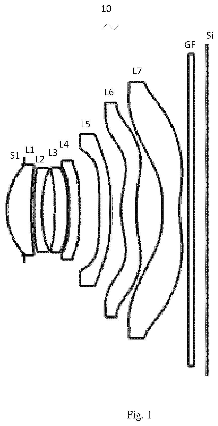
is a schematic diagram of a structure of a camera optical lens in accordance with Embodiment 1 of the present invention;
is a schematic diagram of a longitudinal aberration of the camera optical lens shown in ;
is a schematic diagram of a lateral color of the camera optical lens shown in ;
is a schematic diagram of a field curvature and a distortion of the camera optical lens shown in ;
is a schematic diagram of a structure of a camera optical lens in accordance with Embodiment 2 of the present invention;
is a schematic diagram of a longitudinal aberration of the camera optical lens shown in ;
is a schematic diagram of a lateral color of the camera optical lens shown in ;
is a schematic diagram of a field curvature and a distortion of the camera optical lens shown in ;
is a schematic diagram of a structure of a camera optical lens in accordance with Embodiment 3 of the present invention;
is a schematic diagram of a longitudinal aberration of the camera optical lens shown in ;
is a schematic diagram of a lateral color of the camera optical lens shown in ; and
is a schematic diagram of a field curvature and a distortion of the camera optical lens shown in .
DETAILED DESCRIPTION OF THE EXEMPLARY EMBODIMENTS
In order to make the objects, technical solutions, and advantages of the present invention more apparent, the embodiments of the present invention will be described in detail below. However, it will be apparent to the one skilled in the art that, in the various embodiments of the present invention, a number of technical details are presented in order to provide the reader with a better understanding of the invention. However, the technical solutions claimed in the present invention can be implemented without these technical details and various changes and modifications based on the following embodiments.
Embodiment 1
As referring to the accompanying drawings, the present invention provides a camera optical lens 10 . shows the camera optical lens 10 according to embodiment 1 of the present invention. The camera optical lens comprises seven lenses. Specifically, from an object side to an image side, the camera optical lens 10 comprises in sequence: an aperture S1, a first lens L 1 , a second lens L 2 , a third lens L 3 , a fourth lens L 4 , a fifth lens L 5 , a sixth lens L 6 and a seventh lens L 7 . Optical elements like optical filter GF can be arranged between the seventh lens L 7 and an image surface Si.
The first lens L 1 is made of plastic material, the second lens L 2 is made of plastic material, the third lens L 3 is made of plastic material, the fourth lens L 4 is made of plastic material, the fifth lens L 5 is made of plastic material, the sixth lens L 6 is made of plastic material, and the seventh lens L 7 is made of plastic material. In other optional embodiments, each lens may also be made of other materials.
A central curvature radius of an object side surface of the first lens L 1 is defined as R1, and a central curvature radius of an object side surface of the second lens L 2 is defined as R3. The camera optical lens 10 satisfies the following condition: 5.00≤R3/R1≤10.00, the aberration of the camera optical lens is corrected by reasonably arrange the central curvature radius of the object side surface of the first lens L 1 and the central curvature radius of the object side surface of the second lens L 2 , thereby improving the imaging quality.
In the present embodiment, a central curvature radius of an object side surface of the sixth lens L 6 is defined as R11, and a central curvature radius of an image side surface of the sixth lens L 6 is defined as R12. The camera optical lens 10 further satisfies the following condition: 0.50≤R11/R12≤2.00, which specifies a shape of the sixth lens L 6 . When the condition is satisfied, as the camera optical lens 10 develops toward ultra-thin and wide-angle, it is beneficial for correcting the off-axis aberration.
In the present embodiment, the object side surface of the first lens L 1 is convex in a paraxial region, an image side surface of the first lens L 1 is concave in the paraxial region, and the first lens L 1 has a positive refractive power. In other optional embodiments, the object side surface and the image side surface of the first lens L 1 can also be arranged as other concave side surface or convex side surface, such as, concave object side surface and convex image side surface and so on.
A focal length of the camera optical lens 10 is defined as f, and a focal length of the first lens L 1 is defined as f1. The camera optical lens 10 further satisfies the following condition: 0.37≤f1/f≤1.29, which specifies a ratio of the focal length of the first lens L 1 to the focal length of the camera optical lens 10 . When the condition is satisfied, the first lens has an appropriate positive refractive power, which is beneficial for reducing an aberration of the camera optical lens 10 and developing ultra-thin and wide-angle lenses. Preferably, the following condition shall be satisfied, 0.58≤f1/f≤1.03.
The central curvature radius of the object side surface of the first lens L 1 is defined as R1, and a central curvature radius of the image side surface of the first lens L 1 is defined as R2. The camera optical lens 10 further satisfies the following condition: −3.29≤(R1+R2)/(R1−R2)≤−0.95. This condition reasonably controls a shape of the first lens L 1 , so that the first lens L 1 can effectively correct a spherical aberration of the camera optical lens 10 . Preferably, the following condition shall be satisfied, −2.05≤(R1+R2)/(R1−R2)≤−1.19.
An on-axis thickness of the first lens L 1 is defined as d1. A total optical length from the object side surface of the first lens L 1 to the image surface Si of the camera optical lens 10 along an optical axis is defined as TTL. The camera optical lens 10 further satisfies the following condition: 0.06≤d1/TTL≤0.19. When the condition is satisfied, it benefits for realizing an ultra-thin effect. Preferably, the following condition shall be satisfied, 0.10≤d1/TTL≤0.15.
In the present embodiment, the object side surface of the second lens L 2 is convex in the paraxial region, an image side surface of the second lens L 2 is concave in the paraxial region, and the second lens L 2 has a negative refractive power. In other optional embodiments, the object side surface and the image side surface of the second lens L 2 can also be arranged as other concave side surface or convex side surface, such as, concave object side surface and convex image side surface and so on.
The focal length of the camera optical lens 10 is defined as f, and the focal length of the second lens L 2 is defined as f2. The camera optical lens 10 further satisfies the following condition: −5.27≤f2/f≤−1.40. It is beneficial for correcting the aberration of the camera optical lens 10 by controlling the positive refractive power of the second lens L 2 being within reasonable range. Preferably, the following condition shall be satisfied, −3.29≤f2/f≤−1.75.
The central curvature radius of the object side surface of the second lens L 2 is defined as R3, and a central curvature radius of the image side surface of the second lens L 2 is defined as R4. The camera optical lens further satisfies the following condition: 0.94≤(R3+R4)/(R3−R4)≤4.33, which specifies a shape of the second lens L 2 . When the condition is satisfied, as the camera optical lens 10 develops toward ultra-thin and wide-angle, it is beneficial for correcting the on-axis chromatic aberration. Preferably, the following condition shall be satisfied, 1.51≤(R3+R4)/(R3−R4)≤3.46.
An on-axis thickness of the second lens L 2 is defined as d3. The total optical length from the object side surface of the first lens L 1 to the image surface Si of the camera optical lens 10 along the optical axis is defined as TTL. The camera optical lens 10 further satisfies the following condition: 0.02≤d3/TTL≤0.06. When the condition is satisfied, it is beneficial for producing ultra-thin lenses. Preferably, the following condition shall be satisfied, 0.03≤d3/TTL≤0.05.
In the present embodiment, an object side surface of the third lens L 3 is concave in the paraxial region, an image side surface of the third lens L 3 is convex in the paraxial region, and the third lens L 3 has a negative refractive power. In other optional embodiments, the object side surface and the image side surface of the third lens L 3 can also be arranged as other concave side surface or convex side surface, such as, convex object side surface and concave image side surface and so on.
The focal length of the camera optical lens 10 is defined as f, and the focal length of the third lens L 3 is defined as f3. The camera optical lens further satisfies the following condition: −59.76≤f3/f≤−3.70. By a reasonable distribution of the refractive power, which makes it is possible that the camera optical lens 10 has an excellent imaging quality and a lower sensitivity. Preferably, the following condition shall be satisfied, −37.35≤f3/f≤−4.62.
A central curvature radius of the object side surface of the third lens L 3 is defined as R5, and a central curvature radius of the image side surface of the third lens L 3 is defined as R6. The camera optical lens 10 further satisfies the following condition: −23.25≤(R5+R6)/(R5−R6)≤2.58, which specifies a shape of the third lens L 3 . It is beneficial for molding the third lens L 3 . When the condition is satisfied, a degree of deflection of light passing through the lens can be alleviated, and the aberration can be reduced effectively. Preferably, the following condition shall be satisfied, −14.536 (R5+R6)/(R5−R6)≤2.06.
An on-axis thickness of the third lens L 3 is defined as d5. The total optical length from the object side surface of the first lens L 1 to the image surface Si of the camera optical lens 10 along the optical axis is defined as TTL. The camera optical lens 10 further satisfies the following condition: 0.02≤d5/TTL≤0.11, which benefits for realizing the ultra-thin effect. Preferably, the following condition shall be satisfied, 0.03≤d5/TTL≤0.09.
In the present embodiment, an object side surface of the fourth lens L 4 is convex in the paraxial region, an image side surface of the fourth lens L 4 is concave in the paraxial region, and the fourth lens L 4 has a positive refractive power. In other optional embodiments, the object side surface and the image side surface of the fourth lens L 4 can also be arranged as other convex side surface or concave side surface, such as, concave object side surface and convex image side surface and so on.
The focal length of the camera optical lens 10 is defined as f, and a focal length of the fourth lens L 4 is defined as f4. The camera optical lens 10 further satisfies the following condition: 1.29≤f4/f≤10.42. By a reasonable distribution of the refractive power, which makes it is possible that the camera optical lens 10 has the excellent imaging quality and the lower sensitivity. Preferably, the following condition shall be satisfied, 2.06≤f4/f≤8.33.
A curvature radius of the object side surface of the fourth lens L 4 is defined as R7, and a central curvature radius of the image side surface of the fourth lens L 4 is defined as R8. The camera optical lens further satisfies the following condition: −6.10≤(R7+R8)/(R7−R8)≤1.08, which specifies a shape of the fourth lens L 4 . When the condition is satisfied, as the development of the ultra-thin and wide-angle lenses, it is beneficial for solving the problems, such as correcting the off-axis aberration. Preferably, the following condition shall be satisfied, −3.81≤(R7+R8)/(R7−R8)≤0.86.
An on-axis thickness of the fourth lens L 4 is defined as d7. The total optical length from the object side surface of the first lens L 1 to the image surface Si of the camera optical lens 10 along the optical axis is defined as TTL. The camera optical lens 10 further satisfies the following condition: 0.02≤d7/TTL≤0.11, which is beneficial for realizing the ultra-thin effect. Preferably, the following condition shall be satisfied, 0.04≤d7/TTL≤0.09.
In the present embodiment, an object side surface of the fifth lens L 5 is concave in the paraxial region, an image side surface of the fifth lens L 5 is concave in the paraxial region, and the fifth lens L 5 has a negative refractive power. In other optional embodiments, the object side surface and the image side surface of the fifth lens L 5 can also be arranged as other convex side surface or concave side surface, such as, convex object side surface and convex image side surface and so on.
The focal length of the camera optical lens 10 is defined as f, and a focal length of the fifth lens L 5 is defined as f5. The camera optical lens 10 further satisfies the following condition: −81.12≤f5/f≤−18.68. When the condition is satisfied, a light angle of the camera optical lens 10 can be smoothed effectively and a sensitivity of the tolerance can be reduced. Preferably, the following condition shall be satisfied, −50.70≤f5/f≤−23.35.
A central curvature radius of the object side surface of the fifth lens L 5 is defined as R9, and a central curvature radius of the image side surface of the fifth lens L 5 is defined as R10. The camera optical lens further satisfies the following condition: −51.43≤(R9+R10)/(R9−R10)≤3.50, which specifies a shape of the fifth lens L 5 . When the condition is satisfied, as the development of the ultra-thin and wide-angle lenses, it is beneficial for correcting the off-axis aberration. Preferably, the following condition shall be satisfied, −32.15≤(R9+R10)/(R9−R10)≤2.80.
An on-axis thickness of the fifth lens L 5 is defined as d9. The total optical length from the object side surface of the first lens L 1 to the image surface Si of the camera optical lens 10 along the optical axis is defined as TTL. The camera optical lens 10 further satisfies the following condition: 0.03≤d9/TTL≤0.08. When the condition is satisfied, it is beneficial for realizing the ultra-thin effect. Preferably, the following condition shall be satisfied, 0.04≤d9/TTL≤0.07.
In the present embodiment, the object side surface of the sixth lens L 6 is convex in the paraxial region, the image side surface of the sixth lens L 6 is concave in the paraxial region, and the sixth lens L 6 has a positive refractive power. In other optional embodiments, the object side surface and the image side surface of the sixth lens L 6 can be arranged as other convex side surface or concave side surface, such as, concave object side surface and convex image side surface and so on.
The focal length of the camera optical lens 10 is defined as f, and a focal length of the sixth lens L 6 is defined as f6. The camera optical lens further satisfies the following condition: 0.85≤f6/f≤140.07. By a reasonable distribution of the refractive power, which makes it is possible that the camera optical lens 10 has the excellent imaging quality and the lower sensitivity. Preferably, the following condition shall be satisfied, 1.36≤f6/f≤112.06.
An on-axis thickness of the sixth lens L 6 is defined as d11. The total optical length from the object side surface of the first lens L 1 to the image surface Si of the camera optical lens 10 along the optical axis is defined as TTL. The camera optical lens further satisfies the following condition: 0.04≤d11/TTL≤0.27, which is beneficial for realizing the ultra-thin effect. Preferably, the following condition shall be satisfied, 0.066≤d11/TTL≤0.22.
In the present embodiment, an object side surface of the seventh lens L 7 is concave in the paraxial region, an image side surface of the seventh lens L 7 is concave in the paraxial region, and the seventh lens L 7 has a negative refractive power. In other optional embodiments, the object side surface and the image side surface of the seventh lens L 7 can be arranged as other convex side surface or concave side surface, such as, convex object side surface and convex image side surface and so on.
The focal length of the camera optical lens 10 is defined as f, and a focal length of the seventh lens L 7 is defined as f7. The camera optical lens further satisfies the following condition: −1.88≤f7/f≤−0.49. By a reasonable distribution of the refractive power, which makes it is possible that the camera optical lens 10 has the excellent imaging quality and the lower sensitivity. Preferably, the following condition shall be satisfied, −1.18 f7/f≤−0.61.
A central curvature radius of the object side surface of the seventh lens L 7 is defined as R13, and a central curvature radius of the image side surface of the seventh lens L 7 is defined as R14. The camera optical lens 10 further satisfies the following condition: −0.09≤(R13+R14)/(R13−R14)≤0.78, which specifies a shape of the seventh lens L 7 . When the condition is satisfied, as the development of the ultra-thin and wide-angle lenses, it is beneficial for correcting the off-axis aberration. Preferably, the following condition shall be satisfied, −0.06≤(R13+R14)/(R13−R14)≤0.62.
An on-axis thickness of the seventh lens L 7 is defined as d13. The total optical length from the object side surface of the first lens L 1 to the image surface Si of the camera optical lens 10 along the optical axis is defined as TTL. The camera optical lens further satisfies the following condition: 0.04≤d13/TTL≤0.16, which is beneficial for realizing the ultra-thin effect. Preferably, the following condition shall be satisfied, 0.07≤d13/TTL≤60.13.
In the present embodiment, the focal length of the camera optical lens 10 is f, and a combined focal length of the first lens L 1 and the second lens L 2 is defined as f12. The camera optical lens 10 further satisfies the following condition: 0.50≤f12/f≤1.74. This condition can eliminate aberration and distortion of the camera optical lens 10 , reduce a back focal length of the camera optical lens 10 , and maintain the miniaturization of the camera lens system group. Preferably, the following condition shall be satisfied, 0.80≤f12/f≤1.39.
In the present embodiment, an image height of the camera optical lens 10 is defined as IH. The total optical length from the object side surface of the first lens L 1 to the image surface Si of the camera optical lens 10 along an optical axis is defined as TTL. The camera optical lens 10 further satisfies the following condition: TTL/IH≤1.31, thereby achieving the ultra-thin performance. Preferably, the following condition shall be satisfied, TTL/IH≤1.27.
In the present embodiment, a field of view of the camera optical lens in a diagonal direction is defined as FOV. The FOV is greater than or equal to 80.53°, thereby achieving the wide-angle performance. Preferably, the FOV is greater than or equal to 81.35°.
In the present embodiment, an F number (FNO) of the camera optical lens 10 is smaller than or equal to 2.27, thereby achieving a large aperture and good imaging performance. Preferably, the FNO of the camera optical lens 10 is smaller than or equal to 2.22.
When the above conditions are satisfied, which makes it is possible that the camera optical lens has excellent optical performances, and meanwhile can meet design requirements of ultra-thin, wide-angle and large aperture. According the characteristics of the camera optical lens 10 , it is particularly suitable for a mobile camera lens component and a WEB camera lens composed of high pixel CCD, CMOS.
The following examples will be used to describe the camera optical lens 10 of the present invention. The symbols recorded in each example will be described as follows. The focal length, on-axis distance, central curvature radius, on-axis thickness, inflexion point position, and arrest point position are all in units of mm.
TTL: the total optical length from the object side surface of the first lens L 1 to the image surface Si of the camera optical lens 10 along the optical axis, the unit of TTL is mm.
F number (FNO): a ratio of an effective focal length of the camera optical lens 10 to an entrance pupil diameter (ENPD).
Preferably, inflexion points and/or arrest points can also be arranged on the object side surface and/or image side surface of the lens, so that the demand for high quality imaging can be satisfied, the description below can be referred for specific implementable scheme.
The design information of the camera optical lens 10 in Embodiment 1 of the present invention is shown in the tables 1 and 2.
TABLE 1
R d nd νd
S1 ∞ d0 = −0.662
R1 2.478 d1 = 0.925 nd1 1.5346 ν1 55.69
R2 10.831 d2 = 0.100
R3 12.404 d3 = 0.310 nd2 1.6700 ν2 19.39
R4 6.019 d4 = 0.480
R5 −15.981 d5 = 0.512 nd3 1.5346 ν3 55.69
R6 −18.988 d6 = 0.032
R7 22.280 d7 = 0.380 nd4 1.6700 ν4 19.39
R8 75.968 d8 = 0.777
R9 −154.553 d9 = 0.429 nd5 1.5661 ν5 37.71
R10 424.205 d10 = 0.393
R11 3.276 d11 = 0.572 nd6 1.5438 ν6 56.03
R12 6.486 d12 = 1.005
R13 −9.086 d13 = 0.639 nd7 1.5438 ν7 56.03
R14 3.913 d14 = 0.335
R15 ∞ d15 = 0.210 ndg 1.5168 νg 64.20
R16 ∞ d16 = 0.503
•
• where, the meaning of the various symbols is as follows. • S1: aperture; • R: curvature radius of an optical surface, a central curvature radius for a lens; • R1: central curvature radius of the object side surface of the first lens L 1 ; • R2: central curvature radius of the image side surface of the first lens L 1 ; • R3: central curvature radius of the object side surface of the second lens L 2 ; • R4: central curvature radius of the image side surface of the second lens L 2 ; • R5: central curvature radius of the object side surface of the third lens L 3 ; • R6: central curvature radius of the image side surface of the third lens L 3 ; • R7: central curvature radius of the object side surface of the fourth lens L 4 ; • R8: central curvature radius of the image side surface of the fourth lens L 4 ; • R9: central curvature radius of the object side surface of the fifth lens L 5 ; • R10: central curvature radius of the image side surface of the fifth lens L 5 ; • R11: central curvature radius of the object side surface of the sixth lens L 6 ; • R12: central curvature radius of the image side surface of the sixth lens L 6 ; • R13: central curvature radius of the object side surface of the seventh lens L 7 ; • R14: central curvature radius of the image side surface of the seventh lens L 7 ; • R15: central curvature radius of an object side surface of the optical filter GF; • R16: curvature radius of an image side surface of the optical filter GF; • d: on-axis thickness of a lens and an on-axis distance between lenses; • d0: on-axis distance from the aperture S1 to the object side surface of the first lens L 1 ; • d1: on-axis thickness of the first lens L 1 ; • d2: on-axis distance from the image side surface of the first lens L 1 to the object side surface of the second lens L 2 ; • d3: on-axis thickness of the second lens L 2 ; • d4: on-axis distance from the image side surface of the second lens L 2 to the object side surface of the third lens L 3 ; • d5: on-axis thickness of the third lens L 3 ; • d6: on-axis distance from the image side surface of the third lens L 3 to the object side surface of the fourth lens L 4 ; • d7: on-axis thickness of the fourth lens L 4 ; • d8: on-axis distance from the image side surface of the fourth lens L 4 to the object side surface of the fifth lens L 5 ; • d9: on-axis thickness of the fifth lens L 5 ; • d10: on-axis distance from the image side surface of the fifth lens L 5 to the object side surface of the sixth lens L 6 ; • d11: on-axis thickness of the sixth lens L 6 ; • d12: on-axis distance from the image side surface of the sixth lens L 5 to the object side surface of the seventh lens L 7 ; • d13: on-axis thickness of the seventh lens L 7 ; • d14: on-axis distance from the image side surface of the seventh lens L 7 to the object side surface of the optical filter GF; • d15: on-axis thickness of the optical filter GF; • d16: on-axis distance from the image side surface of the optical filter GF to the image surface; • nd: refractive index of d line (d-line is green light with a wavelength of 550 nm); • nd1: refractive index of d line of the first lens L 1 ; • nd2: refractive index of d line of the second lens L 2 ; • nd3: refractive index of d line of the third lens L 3 ; • nd4: refractive index of d line of the fourth lens L 4 ; • nd5: refractive index of d line of the fifth lens L 5 ; • nd6: refractive index of d line of the sixth lens L 6 ; • nd7: refractive index of d line of the seventh lens L 7 ; • ndg: refractive index of d line of the optical filter GF; • vd: abbe number; • v1: abbe number of the first lens L 1 ; • v2: abbe number of the second lens L 2 ; • v3: abbe number of the third lens L 3 ; • v4: abbe number of the fourth lens L 4 ; • v5: abbe number of the fifth lens L 5 ; • v6: abbe number of the sixth lens L 6 ; • v7: abbe number of the seventh lens L 7 ; • vg: abbe number of the optical filter GF;
Table 2 shows the aspherical surface data of the camera optical lens 10 in Embodiment 1 of the present invention.
TABLE 2
Conic coefficient Aspheric surface coefficients
k A4 A6 A8 A10 A12
R1 2.3507E−01 −9.7264E−03 3.2800E−02 −6.7423E−02 8.1923E−02 −6.1700E−02
R2 0.0000E+00 −2.8745E−03 −2.2231E−02 5.2963E−02 −6.6165E−02 5.1496E−02
R3 0.0000E+00 −1.3910E−02 1.2271E−02 −9.3426E−03 1.1943E−02 −1.0646E−02
R4 0.0000E+00 −1.2793E−03 6.1047E−03 −3.7850E−03 1.3441E−02 −2.0592E−02
R5 0.0000E+00 −9.2126E−03 −1.9540E−02 4.9198E−02 −7.5758E−02 6.9119E−02
R6 0.0000E+00 −1.9245E−01 4.4102E−01 −7.5498E−01 8.8476E−01 −6.9763E−01
R7 0.0000E+00 −1.6766E−01 3.0427E−01 −4.6714E−01 5.0503E−01 −3.7487E−01
R8 0.0000E+00 −4.3456E−02 3.3940E−02 −4.6970E−02 4.6194E−02 −3.0820E−02
R9 0.0000E+00 −1.8434E−02 4.3169E−03 −3.3028E−03 2.2993E−03 −1.2211E−03
R10 0.0000E+00 −4.5161E−02 1.2858E−02 −2.6235E−03 3.2466E−04 3.3869E−05
R11 −7.5207E−01 −2.7004E−02 −3.7480E−03 8.8140E−04 −1.3196E−04 2.5608E−05
R12 0.0000E+00 1.3544E−02 −1.4666E−02 3.8955E−03 −6.4601E−04 7.2884E−05
R13 0.0000E+00 −5.5432E−02 1.6574E−02 −2.7093E−03 2.8795E−04 −2.0432E−05
R14 −1.9847E+01 −3.0781E−02 6.7911E−03 −1.0392E−03 1.0730E−04 −7.4706E−06
Conic coefficient Aspheric surface coefficients
k A14 A16 A18 A20
R1 2.3507E−01 2.9028E−02 −8.3032E−03 1.3201E−03 −8.9540E−05
R2 0.0000E+00 −2.5329E−02 7.6157E−03 −1.2708E−03 8.9540E−05
R3 0.0000E+00 5.9671E−03 −2.0257E−03 3.9204E−04 −3.3759E−05
R4 0.0000E+00 1.7059E−02 −7.9210E−03 1.9631E−03 −1.9837E−04
R5 0.0000E+00 −3.8433E−02 1.2558E−02 −2.1597E−03 1.4573E−04
R6 0.0000E+00 3.6084E−01 −1.1741E−01 2.1821E−02 −1.7668E−03
R7 0.0000E+00 1.8509E−01 −5.8238E−02 1.0594E−02 −8.4668E−04
R8 0.0000E+00 1.3383E−02 −3.6317E−03 5.6113E−04 −3.7361E−05
R9 0.0000E+00 3.9091E−04 −7.2218E−05 6.6915E−06 −2.1712E−07
R10 0.0000E+00 −2.2284E−05 3.7620E−06 −2.8712E−07 8.4556E−09
R11 −7.5207E−01 −3.2418E−06 2.1978E−07 −7.5361E−09 1.0379E−10
R12 0.0000E+00 −5.5570E−06 2.7186E−07 −7.6116E−09 9.1769E−11
R13 0.0000E+00 9.6149E−07 −2.8857E−08 5.0096E−10 −3.8348E−12
R14 −1.9847E+01 3.4390E−07 −1.0029E−08 1.6893E−10 −1.2625E−12
For convenience, an aspheric surface of each lens surface uses the aspheric surfaces shown in the below condition (1). However, the present invention is not limited to the aspherical polynomials form shown in the condition (1). z =( cr 2 )/{1+[1−( k+ 1)( c 2 r 2 )] 1/2 }+A 4 r 4 +A 6 r 6 +A 8 r 8 +A 10 r 10 +A 12 r 12 +A 14 r 14 +A 16 r 16 +A 18 r 18 +A 20 r 20 (1)
Where, K is a conic coefficient, A4, A6, A8, A10, A12, A14, A16, A18, A20 are aspheric surface coefficients. c is the curvature at the center of the optical surface. r is a vertical distance between a point on an aspherical curve and the optic axis, and z is an aspherical depth (a vertical distance between a point on an aspherical surface, having a distance of r from the optic axis, and a surface tangent to a vertex of the aspherical surface on the optic axis).
Table 3 and Table 4 show design data of inflexion points and arrest points of respective lens in the camera optical lens 10 according to Embodiment 1 of the present invention. P1R1 and P1R2 represent the object side surface and the image side surface of the first lens L 1 , P2R1 and P2R2 represent the object side surface and the image side surface of the second lens L 2 , P3R1 and P3R2 represent the object side surface and the image side surface of the third lens L 3 , P4R1 and P4R2 represent the object side surface and the image side surface of the fourth lens L 4 , P5R1 and P5R2 represent the object side surface and the image side surface of the fifth lens L 5 , P6R1 and P 6 R2 represent the object side surface and the image side surface of the sixth lens L 6 , and P7R1 and P7R2 represent the object side surface and the image side surface of the seventh lens L 7 . The data in the column named “inflexion point position” refers to vertical distances from inflexion points arranged on each lens surface to the optical axis of the camera optical lens 10 . The data in the column named “arrest point position” refers to vertical distances from arrest points arranged on each lens surface to the optical axis of the camera optical lens 10 .
TABLE 3
Number of Inflexion Inflexion Inflexion
inflexion points Point position 1 point position 2 point position 3
P1R1 0 / / /
P1R2 1 1.565 / /
P2R1 0 / / /
P2R2 0 / / /
P3R1 0 / / /
P3R2 0 / / /
P4R1 1 0.165 / /
P4R2 2 0.165 1.645 /
P5R1 1 2.225 / /
P5R2 1 0.075 / /
P6R1 2 0.905 2.585 /
P6R2 2 1.105 3.305 /
P7R1 2 2.125 4.685 /
P7R2 3 0.675 4.175 4.935
TABLE 4
Number of Arrest point Arrest point
arrest points position 1 position 2
P1R1 0 / /
P1R2 0 / /
P2R1 0 / /
P2R2 0 / /
P3R1 0 / /
P3R2 0 / /
P4R1 1 0.285 /
P4R2 1 0.285 /
P5R1 1 2.385 /
P5R2 1 0.115 /
P6R1 2 1.545 3.575
P6R2 1 1.785 /
P7R1 1 4.235 /
P7R2 1 1.425 /
and respectively illustrate a longitudinal aberration and a lateral color of light with wavelengths of 650 nm, 555 nm and 470 nm after passing the camera optical lens 10 according to Embodiment 1. illustrates a field curvature and a distortion of light with a wavelength of nm after passing the camera optical lens 10 according to Embodiment 1, in which a field curvature S is a field curvature in a sagittal direction and T is a field curvature in a tangential direction.
Table 13 shows various values of Embodiments 1, 2 and 3 and values corresponding to parameters which are specified in the above conditions.
As shown in Table 13, Embodiment 1 satisfies the above conditions.
In the present embodiment, the entrance pupil diameter (ENPD) of the camera optical lens 10 is 3.433 mm. The image height of 1.0H is 6.247 mm. The FOV is 84.99°. Thus, the camera optical lens 10 satisfies design requirements of large aperture, ultra-thin and wide-angle while the on-axis and off-axis aberrations are sufficiently corrected, thereby achieving excellent optical characteristics.
Embodiment 2
Embodiment 2 is basically the same as Embodiment 1, the meaning of its symbols is the same as that of Embodiment 1, in the following, only the differences are listed.
An image side surface of the fifth lens L 5 is convex in a paraxial region. An object side surface of the sixth lens L 6 is concave in a paraxial region. An image side surface of the sixth lens L 6 is convex in a paraxial region.
shows a schematic diagram of a structure of a camera optical lens 20 according to Embodiment 2 of the present invention. Table 5 and table 6 show the design data of a camera optical lens 20 in Embodiment 2 of the present invention.
TABLE 5
R d nd νd
S1 ∞ d0 = −0.591
R1 2.380 d1 = 0.927 nd1 1.5346 ν1 55.69
R2 13.407 d2 = 0.100
R3 23.791 d3 = 0.310 nd2 1.6700 ν2 19.39
R4 7.317 d4 = 0.372
R5 −25.098 d5 = 0.532 nd3 1.5346 ν3 55.69
R6 −36.489 d6 = 0.030
R7 6.478 d7 = 0.380 nd4 1.6700 ν4 19.39
R8 12.792 d8 = 0.604
R9 −5.513 d9 = 0.411 nd5 1.5444 ν5 55.82
R10 −5.960 d10 = 0.583
R11 −149.803 d11 = 1.405 nd6 1.5661 ν6 37.71
R12 −75.089 d12 = 0.436
R13 −12.068 d13 = 0.686 nd7 1.5444 ν7 55.82
R14 4.677 d14 = 0.335
R15 ∞ d15 = 0.210 ndg 1.5168 νg 64.20
R16 ∞ d16 = 0.475
Table 6 shows aspherical surface data of each lens of the camera optical lens 20 in Embodiment 2 of the present invention.
TABLE 6
Conic coefficient Aspheric surface coefficients
k A4 A6 A8 A10 A12
R1 2.6254E−01 3.1762E−05 −3.1642E−03 −8.3520E−04 6.5841E−03 −8.5965E−03
R2 0.0000E+00 −1.0171E−02 2.6088E−02 −6.4777E−02 1.0120E−01 −9.6934E−02
R3 0.0000E+00 −1.6629E−02 5.1175E−02 −1.2756E−01 2.0926E−01 −2.0921E−01
R4 0.0000E+00 1.3413E−03 −1.7694E−03 1.3406E−03 6.7638E−03 1.4457E−03
R5 0.0000E+00 −2.1767E−02 5.0876E−02 −1.0201E−01 1.0120E−01 −3.8299E−02
R6 0.0000E+00 −2.3192E−01 5.2085E−01 −8.3016E−01 8.8563E−01 −6.3766E−01
R7 0.0000E+00 −1.9674E−01 3.5084E−01 −4.9242E−01 4.5368E−01 −2.7732E−01
R8 0.0000E+00 −2.8727E−02 −1.3275E−02 4.9710E−02 −7.9981E−02 7.0449E−02
R9 0.0000E+00 −1.9466E−02 1.6756E−02 −1.4957E−02 5.8935E−03 7.5610E−04
R10 0.0000E+00 −3.6997E−02 3.8990E−02 −3.9242E−02 3.0395E−02 −1.5282E−02
R11 0.0000E+00 −4.4563E−02 1.3869E−02 −1.4482E−02 1.0717E−02 −4.9742E−03
R12 0.0000E+00 −1.8869E−02 −1.7242E−04 −1.8530E−04 2.7515E−04 −7.3359E−05
R13 0.0000E+00 −4.0848E−02 9.8093E−03 −1.2763E−03 1.1078E−04 −6.6053E−06
R14 −1.0000E+00 −4.5398E−02 1.0862E−02 −1.6632E−03 1.6367E−04 −1.0660E−05
Conic coefficient Aspheric surface coefficients
k A14 A16 A18 A20
R1 2.6254E−01 5.6464E−03 −2.0925E−03 4.1356E−04 −3.3921E−05
R2 0.0000E+00 5.8198E−02 −2.1559E−02 4.5526E−03 −4.2165E−04
R3 0.0000E+00 1.2972E−01 −4.8869E−02 1.0318E−02 −9.4129E−04
R4 0.0000E+00 −1.5062E−02 1.4324E−02 −5.5003E−03 7.8965E−04
R5 0.0000E+00 −1.8877E−02 2.5506E−02 −9.8612E−03 1.3699E−03
R6 0.0000E+00 3.0353E−01 −9.1529E−02 1.5888E−02 −1.2163E−03
R7 0.0000E+00 1.1009E−01 −2.7265E−02 3.9329E−03 −2.6900E−04
R8 0.0000E+00 −3.6917E−02 1.1448E−02 −1.9115E−03 1.3115E−04
R9 0.0000E+00 −2.4313E−03 1.1327E−03 −2.1091E−04 1.3894E−05
R10 0.0000E+00 4.6857E−03 −8.4384E−04 8.2189E−05 −3.3537E−06
R11 0.0000E+00 1.4597E−03 −2.6607E−04 2.7202E−05 −1.1737E−06
R12 0.0000E+00 9.3254E−06 −6.4137E−07 2.3040E−08 −3.4020E−10
R13 0.0000E+00 2.6595E−07 −6.8818E−09 1.0316E−10 −6.8075E−13
R14 −1.0000E+00 4.5804E−07 −1.2500E−08 1.9661E−10 −1.3568E−12
Table 7 and table 8 show design data of inflexion points and arrest points of respective lens in the camera optical lens 20 according to Embodiment 2 of the present invention.
TABLE 7
Number or Inflexion point Inflexion point
inflexion points position 1 position 2
P1R1 0 / /
P1R2 1 1.505 /
P2R1 0 / /
P2R2 0 / /
P3R1 1 1.365 /
P3R2 0 / /
P4R1 1 0.325 /
P4R2 2 0.475 1.435
P5R1 2 1.675 1.865
P5R2 0 / /
P6R1 1 2.235 /
P6R2 0 / /
P7R1 1 2.175 /
P7R2 2 0.745 4.555
TABLE 8
Number of Arrest point Arrest point
arrest points position 1 position 2
P1R1 0 / /
P1R2 0 / /
P2R1 0 / /
P2R2 0 / /
P3R1 0 / /
P3R2 0 / /
P4R1 1 0.695 /
P4R2 2 0.825 1.635
P5R1 0 / /
P5R2 0 / /
P6R1 0 / /
P6R2 0 / /
P7R1 1 4.305 /
P7R2 2 1.775 5.205
and respectively illustrate a longitudinal aberration and a lateral color of light with wavelengths of 650 nm, 555 nm and 470 nm after passing the camera optical lens 20 according to Embodiment 2. illustrates a field curvature and a distortion of light with a wavelength of 555 nm after passing the camera optical lens 10 according to Embodiment 2, in which a field curvature S is a field curvature in a sagittal direction and T is a field curvature in a tangential direction.
As shown in Table 13, Embodiment 2 satisfies the above conditions.
In the present embodiment, an entrance pupil diameter (ENPD) of the camera optical lens is 3.199 mm. An image height of 1.0H is 6.247 mm. An FOV is 82.19°. Thus, the camera optical lens 20 satisfies design requirements of large aperture, ultra-thin and wide-angle while the on-axis and off-axis aberrations are sufficiently corrected, thereby achieving excellent optical characteristics.
Embodiment 3
Embodiment 3 is basically the same as Embodiment 1 and involves symbols having the same meanings as Embodiment 1, and only differences therebetween will be described in the following.
An image side surface of the third lens L 3 is concave in a paraxial region. An image side surface of the fifth lens L 5 is convex in a paraxial region. An object side surface of the sixth lens L 6 is concave in a paraxial region. An image side surface of the sixth lens L 6 is convex in a paraxial region.
shows a schematic diagram of a structure of a camera optical lens 30 according to Embodiment 3 of the present invention.
Tables 9 and 10 show design data of a camera optical lens 30 in Embodiment 3 of the present invention.
TABLE 9
R d nd νd
S1 ∞ d0 = −0.744
R1 2.263 d1 = 0.934 nd1 1.5346 ν1 55.69
R2 10.162 d2 = 0.100
R3 16.974 d3 = 0.310 nd2 1.6700 ν2 19.39
R4 6.304 d4 = 0.362
R5 −152.580 d5 = 0.553 nd3 1.5346 ν3 55.69
R6 361.675 d6 = 0.030
R7 7.040 d7 = 0.380 nd4 1.6700 ν4 19.39
R8 15.876 d8 = 0.506
R9 −8.793 d9 = 0.400 nd5 1.5444 ν5 55.82
R10 −9.716 d10 = 0.732
R11 −14.395 d11 = 1.312 nd6 1.6153 ν6 25.94
R12 −14.395 d12 = 0.357
R13 −14.145 d13 = 0.805 nd7 1.5444 ν7 55.82
R14 4.471 d14 = 0.335
R15 ∞ d15 = 0.210 ndg 1.5168 νg 64.20
R16 ∞ d16 = 0.471
Table 10 shows aspherical surface data of each lens of the camera optical lens 30 in Embodiment 3 of the present invention.
TABLE 10
Conic coefficient Aspheric surface coefficients
k A4 A6 A8 A10 A12
R1 2.7862E−01 −9.1141E−03 2.4942E−02 −5.0396E−02 5.9516E−02 −4.4240E−02
R2 0.0000E+00 −1.3973E−03 2.7510E−02 −6.9544E−02 9.9364E−02 −8.2889E−02
R3 0.0000E+00 4.7884E−03 5.6809E−03 −1.2847E−02 2.2892E−02 −1.7454E−02
R4 0.0000E+00 7.7980E−03 3.3649E−03 −2.0227E−03 7.6372E−03 1.7369E−03
R5 0.0000E+00 −2.0869E−02 5.1310E−02 −9.8307E−02 1.0118E−01 −3.9224E−02
R6 0.0000E+00 −1.8003E−01 2.5715E−01 −2.1547E−01 2.9490E−02 1.3426E−01
R7 0.0000E+00 −1.5327E−01 1.6303E−01 −8.9594E−02 −7.6428E−02 1.8187E−01
R8 0.0000E+00 −1.2763E−02 −5.4323E−02 1.2265E−01 −1.7015E−01 1.4574E−01
R9 0.0000E+00 2.6926E−02 −9.2930E−02 1.4335E−01 −1.4281E−01 9.0220E−02
R10 0.0000E+00 7.1073E−03 −1.8263E−02 1.6118E−02 −7.6967E−03 1.7770E−03
R11 0.0000E+00 −1.2451E−02 −8.8229E−03 2.7448E−03 2.4340E−05 −4.0382E−04
R12 0.0000E+00 −4.5271E−03 −4.1903E−03 8.8664E−04 4.1139E−05 −4.5625E−05
R13 0.0000E+00 −3.7883E−02 8.7427E−03 −1.0906E−03 9.0683E−05 −5.1812E−06
R14 −1.0000E+00 −4.4020E−02 9.8816E−03 −1.4763E−03 1.4267E−04 −8.9865E−06
Conic coefficient Aspheric surface coefficients
k A14 A16 A18 A20
R1 2.7862E−01 2.0872E−02 −6.0992E−03 1.0098E−03 −7.2851E−05
R2 0.0000E+00 4.1292E−02 −1.1903E−02 1.8002E−03 −1.0853E−04
R3 0.0000E+00 5.0397E−03 8.5454E−04 −7.9694E−04 1.2402E−04
R4 0.0000E+00 −1.4647E−02 1.4100E−02 −5.5623E−03 8.2395E−04
R5 0.0000E+00 −1.8978E−02 2.5784E−02 −9.8233E−03 1.3264E−03
R6 0.0000E+00 −1.4965E−01 7.5017E−02 −1.8684E−02 1.8561E−03
R7 0.0000E+00 −1.5292E−01 6.7903E−02 −1.5537E−02 1.4287E−03
R8 0.0000E+00 −7.7913E−02 2.5157E−02 −4.4289E−03 3.2374E−04
R9 0.0000E+00 −3.6482E−02 9.0528E−03 −1.2398E−03 7.1261E−05
R10 0.0000E+00 −8.0735E−05 −4.5060E−05 8.6606E−06 −4.8697E−07
R11 0.0000E+00 1.6085E−04 −3.3242E−05 3.9151E−06 −1.9882E−07
R12 0.0000E+00 8.0241E−06 −6.6991E−07 2.7862E−08 −4.6426E−10
R13 0.0000E+00 2.0034E−07 −4.9987E−09 7.2541E−11 −4.6434E−13
R14 −1.0000E+00 3.6360E−07 −9.0443E−09 1.2507E−10 −7.3047E−13
Table 11 and table 12 show Embodiment 3 design data of inflexion points and arrest points of respective lens in the camera optical lens 30 according to Embodiment 3 of the present invention.
TABLE 11
Number of Inflexion point Inflexion point
inflexion points position 1 position 2
P1R1 0 / /
P1R2 1 1.525 /
P2R1 0 / /
P2R2 0 / /
P3R1 1 1.225 /
P3R2 1 0.045 /
P4R1 1 0.325 /
P4R2 2 0.465 1.405
P5R1 1 1.695 /
P5R2 0 / /
P6R1 2 2.155 2.395
P6R2 1 3.145 /
P7R1 1 2.185 /
P7R2 2 0.775 4.605
TABLE 12
Number of Arrest point Arrest point
arrest points position 1 position 2
P1R1 0 / /
P1R2 0 / /
P2R1 0 / /
P2R2 0 / /
P3R1 0 / /
P3R2 1 0.065 /
P4R1 1 0.645 /
P4R2 2 0.785 1.595
P5R1 0 / /
P5R2 0 / /
P6R1 0 / /
P6R2 0 / /
P7R1 1 4.265 /
P7R2 1 1.775 /
and respectively illustrate a longitudinal aberration and a lateral color of light with wavelengths of 650 nm, 555 nm and 470 nm after passing the camera optical lens 30 according to Embodiment 3. illustrates a field curvature and a distortion of light with a wavelength of 555 nm after passing the camera optical lens 30 according to Embodiment 3, in which a field curvature S is a field curvature in a sagittal direction and T is a field curvature in a tangential direction.
Table 13 in the following lists values corresponding to the respective conditions. In the present Embodiment 3 in order to satisfy the above conditions.
In the present embodiment, an entrance pupil diameter (ENPD) of the camera optical lens is 3.400 mm. An image height of 1.01H is 6.247 mm. An FOV is 82.170. Thus, the camera optical lens 30 satisfies design requirements of large aperture, ultra-thin and wide-angle while the on-axis and off-axis aberrations are sufficiently corrected, thereby achieving excellent optical characteristics.
TABLE 13
Parameters and
conditions Embodiment 1 Embodiment 2 Embodiment 3
R3/R1 5.005 9.995 7.500
R11/R12 0.505 1.995 1.000
f 6.694 7.038 7.139
f1 5.769 5.242 5.213
f2 −17.635 −15.745 −15.009
f3 −200.000 −152.371 −200.000
f4 46.489 18.949 18.387
f5 −199.097 −200.000 −200.000
f6 11.411 262.888 666.667
f7 −4.928 −6.083 −6.126
f12 7.775 7.125 7.149
FNO 1.950 2.200 2.100
TTL 7.602 7.797 7.795
IH 6.247 6.247 6.247
FOV 84.99° 82.19° 82.17°
It is to be understood, however, that even though numerous characteristics and advantages of the present exemplary embodiments have been set forth in the foregoing description, together with details of the structures and functions of the embodiments, the disclosure is illustrative only, and changes may be made in detail, especially in matters of shape, size, and arrangement of parts within the principles of the invention to the full extent indicated by the broad general meaning of the terms where the appended claims are expressed.
Figures (7)
Citations
This patent cites (23)
- US2015/0268448
- US2016/0033742
- US2016/0124191
- US2016/0241756
- US2016/0306140
- US2020/0209560
- US2020/0209592
- US2020/0409059
- US2020/0409103
- US2021/0048611
- US2021/0048634
- US2021/0048646
- US2021/0055514
- US2021/0149159
- US2021/0173184
- US2021/0263282
- US2021/0364741
- US2021/0364747
- US2022/0155562
- US2022/0365317
- US111443461
- US212111955
- US212111955