Illuminating Device Having Two Light Sources Generating Different Etendues and Respective Light Receivers and Display Device
Abstract
Disclosed is an illuminating device, including first and second light sources, first and second light receiving elements, a display module, and a projection module. The first and second light sources are for generating first and second light beam respectively. The first and second light receiving elements, located on the optical paths of the first and second light beams respectively, are for converging the first and second light beams respectively. The display module, located on the optical paths of the first and the second light beams, receives the first and second light beams and generates corresponding first and second image beams respectively. The projection module, located on the optical paths of the first and second image beams, projects the first and second image beams. A first etendue of the first light beam is greater than a second etendue of the second light beam.
Claims (18)
1. An illuminating device, comprising: a first light source for generating a first light beam; a second light source for generating a second light beam; a first light receiving element located on an optical path of the first light beam, wherein the first light receiving element is used for converging the first light beam; a second light receiving element located on an optical path of the second light beam, wherein the second light receiving element is used for converging the second light beam; a display module located on the optical path of the first light beam and the optical path of the second light beam, wherein the display module receives the first light beam and the second light beam and generates a first image beam corresponding to the first light beam and a second image beam corresponding to the second light beam; and a projection module located on an optical path of the first image beam and an optical path of the second image beam, wherein the projection module is used for projecting the first image beam and the second image beam, the first light beam having a first etendue and the second light beam having a second etendue, wherein the first etendue is greater than the second etendue.
Show 17 dependent claims
2. The illuminating device of claim 1 , wherein a ratio of the first etendue to the second etendue is 10-50.
3. The illuminating device of claim 1 , wherein the first light source is a light-emitting diode array or a phosphor.
4. The illuminating device of claim 1 , wherein the second light source is a laser.
5. The illuminating device of claim 1 , wherein each of the first light beam and the second light beam is a white light.
6. The illuminating device of claim 1 , wherein the first light receiving element is a focusing lens or a collimating lens.
7. The illuminating device of claim 1 , wherein the second light receiving element is a focusing lens or a collimating lens.
8. The illuminating device of claim 1 , wherein an effective focal length of the first light receiving element is not equal to an effective focal length of the second light receiving element.
9. The illuminating device of claim 1 , further comprising a reflective element, wherein the reflective element is located on the optical path of the first light beam and at a downstream of the first light receiving element, the reflective element being used for reflecting a part of the first light beam.
10. The illuminating device of claim 1 , further comprising a reflective element, wherein the reflective element is located on the optical path of the second light beam and at a downstream of the second light receiving element, the reflective element being used for reflecting a part of the second light beam.
11. The illuminating device of claim 1 , further comprising a light combining element, wherein the light combining element is located on the optical path of the first light beam, the light combining element being located at a downstream of the first light receiving element, wherein a direction of travel of the first light beam is parallel to a direction of travel of the second light beam in response to the first light beam being incident on the light combining element and reflected by the light combining element.
12. The illuminating device of claim 1 , further comprising a light combining element, wherein the light combining element is located on the optical path of the second light beam, the light combining element being located at a downstream of the second light receiving element, wherein a direction of travel of the second light beam is parallel to a direction of travel of the first light beam in response to the second light beam being incident on the light combining element and reflected by the light combining element.
13. The illuminating device of claim 1 , further comprising a light combining element, wherein the light combining element is located on the optical path of the first light beam and the optical path of the second light beam, the light combining element being located at a downstream of the first light receiving element and a downstream of the second light receiving element, wherein a direction of travel of the first light beam is parallel to a direction of travel of the second light beam in response to the first light beam and the second light beam being incident on the light combining element and reflected by the light combining element, respectively.
14. The illuminating device of claim 1 , further comprising a diffusion element, wherein the diffusion element is located on the optical path of the first light beam and at a downstream of the first light receiving element, the diffusion element being used for enabling the first light beam with a uniform energy distribution.
15. The illuminating device of claim 1 , further comprising a diffusion element, wherein the diffusion element is located on the optical path of the second light beam and at a downstream of the second light receiving element, the diffusion element being used for enabling the second light beam with a uniform energy distribution.
16. The illuminating device of claim 1 , further comprising a diffusion element, wherein the diffusion element is located on the optical path of the first light beam and the optical path of the second light beam, the diffusion element being located at a downstream of the first light receiving element and a downstream of the second light receiving element, wherein the diffusion element is used for enabling the first light beam and the second light beam with a uniform energy distribution.
17. The illuminating device of claim 1 , wherein the display module is a digital mirror device, a penetrating display, or a reflective display.
18. The illuminating device of claim 1 , wherein the first image beam comprises the whole second image beam.
Full Description
Show full text →
CROSS-REFERENCE TO RELATED APPLICATION
This application claims the priority benefit of China application serial no. 202311257410.X, filed on Sep. 27, 2023. The entirety of the above-mentioned patent application is hereby incorporated by reference herein and made a part of this specification.
BACKGROUND
Technical Field
The disclosure relates to an illuminating device.
Description of Related Art
When a vehicle is driven at night or under poor ambient lighting conditions, the visual field of the driver is affected, causing a severe impact on driving safety. Therefore, vehicles need to have good low beam illumination and high beam illumination at the same time. Low beam illumination is for illuminating nearer grounds in the front to ensure visibility. High beam illumination is for improving the visibility of the road at night so as to clarify the situation on the road in the distance.
SUMMARY
The disclosure provides an illuminating device to provide low beam illumination and high beam illumination at the same time.
An illuminating device of the disclosure includes: a first light source for generating a first light beam; a second light source for generating a second light beam; a first light receiving element located on an optical path of the first light beam and for converging the first light beam; a second light receiving element located on an optical path of the second light beam and for converging the second light beam; a display module, which is located on the optical path of the first light beam and the optical path of the second light beam, receives the first light beam and the second light beam and generates a first image beam corresponding to the first light beam and a second image beam corresponding to the second light beam; and a projection module, which is located on an optical path of the first image beam and an optical path of the second image beam, projects the first image beam and the second image beam, wherein the first light beam has a first etendue and the second light beam has a second etendue, and the first etendue is greater than the second etendue.
In an embodiment of the disclosure, a ratio of the first etendue to the second etendue is 10-50.
In an embodiment of the disclosure, the first light source is a light-emitting diode array or a phosphor.
In an embodiment of the disclosure, the second light source is a laser.
In an embodiment of the disclosure, each of the first light beam and the second light beam is a white light.
In an embodiment of the disclosure, the first light receiving element is a focusing lens or a collimating lens.
In an embodiment of the disclosure, the second light receiving element is a focusing lens or a collimating lens.
In an embodiment of the disclosure, an effective focal length of the first light receiving element is not equal to an effective focal length of the second light receiving element.
In an embodiment of the disclosure, the illuminating device further includes a reflective element. The reflective element is located on the optical path of the first light beam and at a downstream of the first light receiving element. The reflective element is for reflecting a part of the first light beam.
In an embodiment of the disclosure, the illuminating device further includes a reflective element. The reflective element is located on the optical path of the second light beam and at a downstream of the second light receiving element. The reflective element is for reflecting a part of the second light beam.
In an embodiment of the disclosure, the illuminating device further includes a light combining element. The light combining element is located on the optical path of the first light beam and at a downstream of the first light receiving element. A direction of travel of the first light beam is parallel to a direction of travel of the second light beam in response to the first light beam being incident on the light combining element and reflected by the light combining element.
In an embodiment of the disclosure, the illuminating device further includes a light combining element. The light combining element is located on the optical path of the second light beam and at a downstream of the second light receiving element. A direction of travel of the second light beam is parallel to a direction of travel of the first light beam in response to the second light beam being incident on the light combining element and reflected by the light combining element.
In an embodiment of the disclosure, the illuminating device further includes a light combining element. The light combining element is located on the optical path of the first light beam and the optical path of the second light beam. The light combining element is also located at a downstream of the first light receiving element and a downstream of the second light receiving element. A direction of travel of the first light beam is parallel to a direction of travel of the second light beam in response to the first light beam and the second light beam being incident on the light combining element and reflected by the light combining element, respectively.
In an embodiment of the disclosure, the illuminating device further includes a diffusion element. The diffusion element is located on the optical path of the first light beam and at a downstream of the first light receiving element. The diffusion element is for enabling the first light beam with a uniform energy distribution.
In an embodiment of the disclosure, the illuminating device further includes a diffusion element. The diffusion element is located on the optical path of the second light beam and at a downstream of the second light receiving element. The diffusion element is for enabling the second light beam with a uniform energy distribution.
In an embodiment of the disclosure, the illuminating device further includes a diffusion element. The diffusion element is located on the optical path of the first light beam and the optical path of the second light beam. The diffusion element is also located at a downstream of the first light receiving element and a downstream of the second light receiving element. The diffusion element is for enabling the first light beam and the second light beam with a uniform energy distribution.
In an embodiment of the disclosure, the display module is a digital mirror device, a penetrating display, or a reflective display.
In an embodiment of the disclosure, the first image beam includes the whole second image beam.
Based on the above, the illuminating device described in the disclosure utilizes light sources with different etendues to present a required energy distribution on the projected scene. In addition, by reducing the optical path, a plurality of groups of light sources are combined into the illuminating device and projected into the environment.
BRIEF DESCRIPTION OF THE DRAWINGS
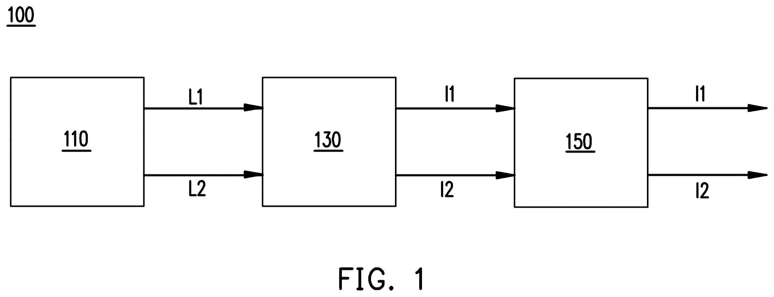
is a block diagram of an illuminating device according to some embodiments of the disclosure.
is a schematic diagram of an illuminating device according to some embodiments of the disclosure.
is a schematic diagram of an illuminating device according to some embodiments of the disclosure.
is a schematic diagram of an illuminating device according to some embodiments of the disclosure.
is a schematic diagram of an illuminating device according to some embodiments of the disclosure.
is a schematic diagram of an illuminating device according to some embodiments of the disclosure.
is a schematic diagram of an illuminating device according to some embodiments of the disclosure.
is a schematic diagram of an illuminating device according to some embodiments of the disclosure.
is a schematic diagram of an illuminating device according to some embodiments of the disclosure.
A to 10 F are schematic diagrams of an energy distribution of an image beam according to some embodiments of the disclosure.
DESCRIPTION OF THE EMBODIMENTS
is a block diagram of an illuminating device according to some embodiments of the disclosure. An illuminating device 100 includes: a light source module 110 , a display module 130 , and a projection module 150 . The light source module 110 is for generating a first light beam L 1 and a second light beam L 2 . The display module 130 is located on an optical path of the first light beam L 1 and an optical path of the second light beam L 2 . The display module 130 receives the first light beam L 1 and the second light beam L 2 , and generates a first image beam I 1 corresponding to the first light beam L 1 and a second image beam I 2 corresponding to the second light beam L 2 . The projection module 150 is located on an optical path of the first image beam I 1 and an optical path of the second image beam I 2 , and for projecting the first image beam I 1 and the second image beam I 2 .
The light source module 110 , the display module 130 , and the projection module 150 are separately described below.
is a schematic diagram of an illuminating device according to some embodiments of the disclosure. A light source module 110 A is an embodiment of the light source module 110 in . The light source module 110 A includes a first light source 112 A and a second light source 112 B. The first light source 112 A is for generating the first light beam L 1 . The second light source 112 B is for generating the second light beam L 2 . In some embodiments, each of the first light beam L 1 and the second light beam L 2 is a white light. In some embodiments, the first light beam L 1 and the second light beam L 2 have the same color temperature. For example, both the first light beam L 1 and the second light beam L 2 may have a color temperature of 6000K.
In terms of vehicle illumination, a light beam needed for low beam illumination need to have a uniform brightness and a wide lighting range when it comes to the property of the light beam. A light beam needed for high beam illumination need to have high brightness and a limited lighting range when it comes to the property of the light beam. Therefore, the first light beam L 1 and the second light beam L 2 need to meet different properties.
On the other hand, in the field of optics, an etendue of a light beam is related to a cross-sectional area through which the light beam passes and a corresponding solid angle, that is, the etendue is proportional to a product of the cross-sectional area through which the light beam passes and the corresponding solid angle. In some embodiments, the first light beam L 1 has a first etendue and the second light beam L 2 has a second etendue, and the first etendue is greater than the second etendue. As a result, the first light beam L 1 with the greater etendue has a wider lighting range and is for providing a wider and more uniform projection, which makes the first light beam L 1 suitable for providing low beam illumination. The second light beam L 2 with the smaller etendue has a more limited lighting range and is for providing a more limited and focused projection, which makes the second light beam L 2 suitable for providing high beam illumination.
In some embodiments, the first light source 112 A includes a light-emitting diode array, phosphor, or one other light source that can emit a light beam with a greater etendue. However, the disclosure is not limited thereto. In some embodiments, the second light source 112 B is a laser or one other light source that emits a light beam with a smaller etendue. However, the disclosure is not limited thereto.
In some embodiments, the ratio of the first etendue to the second etendue is 10-50, but the disclosure is not limited thereto. There may be other ranges depending on the actual requirements. For example, in some embodiments, the first light beam L 1 generated by the first light source 112 A passes through a cross-sectional area of 3.5 mm×1.4 mm, and a positive or a negative angle between the light beam and an optical axis is 80 degrees, making a corresponding etendue 14.9. The second light beam L 2 generated by the second light source 112 B passes through a cross-sectional area of 1.0 mm×0.5 mm, and a positive or a negative angle between the light beam and an optical axis is 30 degrees, making a corresponding etendue 0.4.
As shown in , the light source module 110 A further includes a first light receiving element 114 A and a second light receiving element 114 B. The first light receiving element 114 A is located on an optical path of the first light beam L 1 for converging the first light beam L 1 . The second light receiving element 114 B is located on an optical path of the second light beam L 2 for converging the second light beam L 2 .
In some embodiments, the first light receiving element 114 A is a focusing lens or a collimating lens or one other optical element having similar characteristics, but the disclosure is not limited thereto. Therefore, when the first light beam L 1 passes through the first light receiving element 114 A, the first light beam L 1 may be converged through a focusing or collimating effect of the first light receiving element 114 A. In some embodiments, the first light source 112 A may be located at a focal point of the first light receiving element 114 A to enable the first light receiving element 114 A with a better focusing or collimating effect.
In some embodiments, the second light receiving element 114 B is a focusing lens or a collimating lens or one other optical element having similar characteristics, but the disclosure is not limited thereto. Therefore, when the second light beam L 2 passes through the second light receiving element 114 B, the second light beam L 2 may be converged through a focusing or collimating effect of the second light receiving element 114 B. In some embodiments, the second light source 112 B may be located at a focal point of the second light receiving element 114 B to enable the second light receiving element 114 B with a better focusing or collimating effect.
In some embodiments, an effective focal length (EFL) of the first light receiving element 114 A is not equal to an EFL of the second light receiving element 114 B. Due to the first light receiving element 114 A and the second light receiving element 114 B having different EMLs, the first light receiving element 114 A and the second light receiving element 114 B are capable of converging a light beam in different ways depending on the requirements, and further increasing or decreasing a projection range as well as an intensity of brightness and an intensity of energy.
In some embodiments, the first light beam L 1 generated by the first light source 112 A has a higher brightness than a needed brightness. Thus, the brightness of the first light beam L 1 needs to be adjusted. Please refer to . The light source module 110 A further includes a reflective element 120 A. The reflective element 120 A is located on the optical path of the first light beam L 1 and at a downstream of the first light receiving element 114 A. The reflective element 120 A is for reflecting a light beam L 1 ′, which is partial of the first light beam L 1 .
The reflective element 120 A reflects the partial light beam L 1 ′ of the first light beam L 1 to enable the first light beam L 1 with an appropriate intensity. On the other hand, the partial light beam L 1 ′ reflected by the reflective element 120 A may return to the first light source 112 A through the light receiving element 114 A. That is, the light beam L 1 ′ may be retrieved to the first light source 112 A through this path.
By adjusting the reflective element 120 A, a proportion of reflection relative to a proportion of penetration of the first light beam L 1 through the first light receiving element 114 A on an optical path can be adjusted. By adjusting the proportions of reflection and penetration of the first light beam L 1 through the first light receiving element 114 A, a projection with a wider range and a more uniform brightness generated corresponding to the first light beam L 1 may be adjusted. For example, the more the proportion of the first light beam L 1 penetrating the first light receiving element 114 A, the brighter the projection generated by the first light beam L 1 .
According to some embodiments, the reflective element 120 A may be a reflector, an optical element having a metallic reflective coating, or one other element having similar functions. The disclosure is not limited thereto. In some embodiments, a width d 1 of the reflective element 120 A on an optical axis of the first light beam L 1 is less than or equal to a half of a width D 1 of the light receiving element 114 A on the optical axis of the first light beam L 1 . In some embodiments, the reflective element 120 A may be omitted.
In some embodiments, the first light beam L 1 emitted from the first light source 112 A and the second light beam L 2 emitted from the second light source 112 B do not have a same direction of travel. Thus, a light combining element is needed to make a direction of travel of the first light beam L 1 and a direction of travel of the second light beam L 2 the same.
As shown in , the light source module 110 A further includes a light combining element 122 B. The light combining element 122 B is located on the optical path of the second light beam L 2 . On the other hand, the light combining element 122 B is not located on the optical path of the first light beam L 1 . Thus, the light combining element 122 B is only for changing the optical path of the second light beam L 2 .
The light combining element 122 B is located at a downstream of the second light receiving element 114 B. When the second light beam L 2 is incident on the light combining element 122 B and reflected by the light combining element 122 B, the direction of travel of the second light beam L 2 is parallel to the direction of travel of the first light beam L 1 .
In some embodiments, the light combining element 122 B may be a reflector, an optical element having a metallic reflective coating, or one other element having similar functions. The disclosure is not limited thereto. When the second light beam L 2 is incident on the light combining element 122 B, the second light beam L 2 is reflected by the light combining element 122 B and thus has the same direction of travel as the first light beam L 1 . After the second light beam L 2 passes through the light combining element 122 B, the first light beam L 1 has the same direction of travel as the second light beam L 2 . In some embodiments, the second light beam L 2 is completely included in the first light beam L 1 .
As a result, as shown with the light source module 110 A in , the first light source 112 A and the second light source 112 B generate the first light beam L 1 and the second light beam L 2 respectively. After the first light beam L 1 passes through the light receiving element 114 A, the intensity of the first light beam L 1 is controlled by the reflective element 120 A. After the second light beam passes through the light receiving element 114 B, the optical path of the second light beam is changed by the light combining element 122 B. Thus, the second light beam has the same direction of travel as the first light beam L 1 . Subsequently, the first light beam L 1 and the second light beam L 2 are incident on the display module 130 (as shown in ).
is a schematic diagram of an illuminating device according to some embodiments of the disclosure. A light source module 110 B is an embodiment of the light source module 110 in . As the light source module 110 B has a similar structure to the light source module 110 A shown in , the similarities will not be described herein. Differences between the light source module 110 B and the light source module 110 A are described below.
As shown in , the light source module 110 B includes a reflective element 120 B. The reflective element 120 B is located on the optical path of the second light beam L 2 and at the downstream of the second light receiving element 114 B. The reflective element 120 B is for reflecting a light beam L 2 ′, which is partial of the second light beam L 2 .
The reflective element 120 B reflects the partial light beam L 2 ′ of the second light beam L 2 to enable the second light beam L 2 with an appropriate intensity. On the other hand, the partial light beam L 2 ′ reflected by the reflective element 120 B may return to the second light source 112 B through the light receiving element 114 B. That is, the light beam L 2 ′ may be retrieved to the second light source 112 B through this path.
According to some embodiments, the reflective element 120 B may be a reflector, an optical element having a metallic reflective coating, or one other element having similar functions. The disclosure is not limited thereto. In some embodiments, a width d 2 of the reflective element 120 B on an optical axis of the second light beam L 2 is less than or equal to a half of a width D 2 of the light receiving element 114 B on the optical axis of the second light beam L 2 . In some embodiments, the reflective element 120 B may be omitted.
Compared to the light source module 110 A shown in , the light source module 110 B does not have the light combining element 122 B. As shown in , the light source module 110 B further includes a light combining element 122 A. The light combining element 122 A is located on the optical path of the first light beam L 1 . On the other hand, the light combining element 122 A is not located on the optical path of the second light beam L 2 . Thus, the light combining element 122 A is only for changing the optical path of the first light beam L 1 .
The light combining element 122 A is located at the downstream of the first light receiving element 114 A. When the first light beam L 1 is incident on the light combining element 122 A and reflected by the light combining element 122 A, the direction of travel of the first light beam L 1 is parallel to the direction of travel of the second light beam L 2 .
In some embodiments, the light combining element 122 A may be a reflector, an optical element having a metallic reflective coating, or one other element having similar functions. The disclosure is not limited thereto. When the first light beam L 1 is incident on the light combining element 122 A, the first light beam L 1 is reflected by the light combining element 122 A and thus has the same direction of travel as the second light beam L 2 . After the first light beam L 1 passes through the light combining element 122 A, the first light beam L 1 has the same direction of travel as the second light beam L 2 . In some embodiments, the second light beam L 2 is completely included in the first light beam L 1 .
As a result, as shown with the light source module 110 B in , the first light source 112 A and the second light source 112 B generate the first light beam L 1 and the second light beam L 2 respectively. After the first light beam L 1 passes through the light receiving element 114 A, the intensity of the first light beam L 1 is controlled by the reflective element 120 A, and the optical path is changed by the light combining element 122 A. Thus, the first light beam L 1 has the same direction of travel as the second light beam L 2 . After the second light beam L 2 passes through the light receiving element 114 B, the intensity of the second light beam L 2 is controlled by the reflective element 120 B. Subsequently, the first light beam L 1 and the second light beam L 2 are incident on the display module 130 (as shown in ).
In the light source module 110 A and the light source module 110 B, the first light beam L 1 emitted by the first light source 112 A and the second light beam L 2 emitted by the second light source 112 B shown in and are approximately perpendicular to each other. In some embodiments, the first light beam emitted by the first light source and the second light beam emitted by the second light source are approximately parallel or opposite to each other.
is a schematic diagram of an illuminating device according to some embodiments of the disclosure. A light source module 110 C is an embodiment of the light source module 110 in . As the light source module 110 C has a similar structure to the light source module 110 A shown in , the similarities will not be described herein. Differences between the light source module 110 C and the light source module 110 A are described below.
In the light source module 110 A shown in , a light emitting direction of the first light source 112 A and a light emitting direction of the second light source 112 B are approximately perpendicular to each other. On the contrary, the first light source 112 A and the second light source 112 B of the light source module 110 C shown in are configured opposite to each other, making the light emitting direction of the first light source 112 A and the light emitting direction the second light source 112 B parallel to each other.
The first light source 112 A and the second light source 112 B generate the first light beam L 1 and the second light beam L 2 respectively. After the first light beam L 1 passes through the light receiving element 114 A, the intensity of the first light beam L 1 is controlled by the reflective element 120 A, and the first light beam L 1 is incident on a light combining element 122 C. After the second light beam L 2 passes through the light receiving element 114 B, the second light beam L 2 is incident on the light combining element 122 C.
As shown in , the light combining element 122 C is located on the optical path of the first light beam L 1 and the optical path of the second light beam L 2 . The light combining element 122 C is also located at the downstream of the first light receiving element 114 A and the downstream of the second light receiving element 114 B. When the first light beam L 1 and the second light beam L 2 are respectively incident on the light combining element 122 C and reflected by the light combining element 122 C, the direction of travel of the first light beam L 1 is parallel to the direction of travel of the second light beam L 2 . After the first light beam L 1 and the second light beam L 2 pass through the light combining element 122 C, the first light beam L 1 has the same direction of travel as the second light beam L 2 . In some embodiments, the second light beam L 2 is completely included in the first light beam L 1 .
Specifically, the first light beam L 1 is incident on a first surface 122 C 1 of the light combining element 122 C and reflected by the first surface 122 C 1 . The second light beam L 2 is incident on a second surface 122 C 2 of the light combining element 122 C and reflected by the second surface 122 C 2 . The first light beam L 1 reflected by the first surface 122 C 1 and the second light beam L 2 reflected by the second surface 122 C 2 have the same direction of travel and are incident on the display module 130 (as shown in ).
In some embodiments, the light combining element 122 C may be a reflector having two different reflective surfaces or one other element having similar functions, but the disclosure is not limited thereto.
In this embodiment, the light source module 110 C has a reflective element 120 C, which is similar to the reflective element 120 A of the light source module 110 A shown in and is used for reflecting the partial light beam L 1 ′ of the first light beam L 1 to enable the first light beam L 1 with an appropriate intensity. In some embodiments, the reflective element 120 C is part of the light combining element 122 C. This is for reducing the number of elements of the light source module 110 C.
According to some embodiments, the reflective element 120 C may be a reflector, an optical element having a metallic reflective coating, or one other element having similar functions. The disclosure is not limited thereto.
As a result, as shown with the light source module 110 C in , the first light source 112 A and the second light source 112 B generate the first light beam L 1 and the second light beam L 2 respectively. After the first light beam L 1 passes through the light receiving element 114 A, the intensity of the first light beam L 1 is controlled by the reflective element 120 C, and the optical path of the first light beam L 1 is changed as the first light beam L 1 is reflected by the first surface 122 C 1 of the light combining element 122 C. After the second light beam L 2 passes through the light receiving element 114 B, the optical path of the second light beam L 2 is changed as the second light beam L 2 is reflected by the second surface 122 C 2 of the light combining element 122 C. After the optical path of the first light beam L 1 is changed by the light combining element 122 C, the first light beam L 1 has the same direction of travel as the second light beam L 2 . Subsequently, the first light beam L 1 and the second light beam L 2 are incident on the display module 130 (as shown in ).
is a schematic diagram of an illuminating device according to some embodiments of the disclosure. A light source module 110 D is an embodiment of the light source module 110 in . As the light source module 110 D has a similar structure to the light source module 110 C shown in , the similarities will not be described herein. Differences between the light source module 110 D and the light source module 110 C are described below.
In this embodiment, the light source module 110 D further has a reflective element 120 D, which is similar to the reflective element 120 B of the light source module 110 B shown in and is used for reflecting the partial light beam L 2 ′ of the second light beam L 2 to enable the second light beam L 2 with an appropriate intensity. In some embodiments, the reflective element 120 D is part of the light combining element 122 C. This is for reducing the number of elements of the light source module 110 D.
According to some embodiments, the reflective element 120 D may be a reflector, an optical element having a metallic reflective coating, or one other element having similar functions. The disclosure is not limited thereto.
As a result, as shown with the light source module 110 D in , the first light source 112 A and the second light source 112 B generate the first light beam L 1 and the second light beam L 2 respectively. After the first light beam L 1 passes through the light receiving element 114 A, the intensity of the first light beam L 1 is controlled by the reflective element 120 C, and the optical path of the first light beam L 1 is changed as the first light beam L 1 is reflected by the first surface 122 C 1 of the light combining element 122 C. After the second light beam L 2 passes through the light receiving element 114 B, the intensity of the second light beam L 2 is controlled by the reflective element 120 D, and the optical path of the second light beam L 2 is changed as the second light beam L 2 is reflected by the second surface 122 C 2 of the light combining element 122 C. After the optical path of the first light beam L 1 is changed by the light combining element 122 C, the first light beam L 1 has the same direction of travel as the second light beam L 2 . Subsequently, the first light beam L 1 and the second light beam L 2 are incident on the display module 130 (as shown in ).
is a schematic diagram of an illuminating device according to some embodiments of the disclosure. A light source module 110 E is an embodiment of the light source module 110 in . As the light source module 110 E has a similar structure to the light source module 110 A shown in , the similarities will not be described herein. Differences between the light source module 110 E and the light source module 110 A are described below.
In order to enable the first light beam L 1 and the second light beam L 2 emitted by the light source module 110 E with a uniform brightness, a diffusion element may be added at an appropriate position to make the energy or brightness of one or both of the first light beam L 1 and the second light beam L 2 uniform. This is for adjusting an obvious step-wise decrease in brightness between the first light source 110 A and the second light source 110 B, and to make an overall brightness distribution smoother.
In some embodiments, the light source module 110 E includes a diffusion element 124 A. The diffusion element 124 A is located on the optical path of the first light beam L 1 and at the downstream of the first light receiving element 114 A to enable the first light beam L 1 with a uniform energy distribution.
In some embodiments, the light source module 110 E includes a diffusion element 124 B. The diffusion element 124 B is located on the optical path of the second light beam L 2 and at the downstream of the second light receiving element 114 B to enable the second light beam L 2 with a uniform energy distribution.
In some embodiments, the light source module 110 E includes a diffusion element 124 C. The diffusion element 124 C is located on the optical path of the first light beam L 1 and the optical path of the second light beam L 2 and at the downstream of the first light receiving element 114 A and the downstream of the second light receiving element 114 B to enable the first light beam L 1 and the second light beam L 2 with a uniform energy distribution.
In some embodiments, any one of the diffusion element 124 A, the diffusion element 124 B, or the diffusion element 124 C may be added depending on the actual requirements. However, the disclosure is not limited thereto. In some embodiments, the diffusion element 124 A, the diffusion element 124 B, or the diffusion element 124 C may be configured in any one of the aforementioned light source modules 110 A to 110 D, and the disclosure is not limited thereto.
is a schematic diagram of an illuminating device according to some embodiments of the disclosure. As shown in , an illuminating device 100 A includes a light source module 110 C, a display module 130 A, and the projection module 150 .
The light source module 110 C is for generating the first light beam L 1 and the second light beam L 2 . A structure of the light source module 110 C is shown in and will not be described herein. In other embodiments, the light source module may be any one of the light source modules 110 A to 110 E shown in to 6 , and the disclosure is not limited thereto.
The first light beam L 1 and the second light beam L 2 emitted by the light source module 110 C are incident on a reflector 132 , and then reflected by the reflector 132 to the display module 130 A. The reflector 132 is for changing the optical path of the first light beam L 1 and the optical path of the second light beam L 2 to achieve an effect of reducing a system volume. In some embodiments, the reflector 132 may be a curved reflector or one other optical element having similar characteristics, but the disclosure is not limited thereto.
The first light beam L 1 and the second light beam L 2 are reflected by the reflector 132 and then incident on the display module 130 A. The display module 130 A receives the first light beam L 1 and the second light beam L 2 , and generates the first image beam I 1 corresponding to the first light beam L 1 and the second image beam I 2 corresponding to the second light beam L 2 . The display module 130 A is an embodiment of the display module 130 in . In this embodiment, the display module 130 A is a digital mirror device (DMD). In this embodiment, light emitting surfaces of the first light source 112 A and the second light source 112 B are in an object-image relationship with the display module 130 A, i.e., the DMD. In other words, both the light emitting surfaces of the first light source 112 A and the second light source 112 B are magnified and imaged on the display module 130 A.
The first image beam I 1 and the second image beam I 2 emitted by the display module 130 A are incident on the projection module 150 . The projection module 150 is located on the optical path of the first image beam I 1 and the optical path of the second image beam I 2 , and for projecting the first image beam I 1 and the second image beam I 2 . In some embodiments, the second image beam I 2 is completely included in the first image beam I 1 . In some embodiments, a center of the second image beam I 2 overlaps a center of the first image beam I 1 . According to some embodiments, the projection module 150 is a combination of one or a plurality of optical lenses having a diopter, including, for example, a variety of combinations of biconcave lenses, biconvex lenses, concave-convex lenses, convex-concave lenses, plano-convex lenses, and plano-concave lenses, and other non-planar lenses. A type of the projection module 150 of the disclosure and a sort thereof are not limited.
is a schematic diagram of an illuminating device according to some embodiments of the disclosure. As shown in , an illuminating device 100 B includes the light source module 110 C, a display module 130 B, and the projection module 150 .
The light source module 110 C is for generating the first light beam L 1 and the second light beam L 2 . The structure of the light source module 110 C is shown in and will not be described herein. In other embodiments, the light source module may be any one of the light source modules 110 A to 110 E shown in to 6 , and the disclosure is not limited thereto.
After the light source module 110 C emits the first light beam L 1 and the second light beam L 2 , the first light beam L 1 and the second light beam L 2 are incident on a lens assembly 134 . The lens assembly 134 can be used for changing an optical property of the first light beam L 1 and an optical property of the second light beam L 2 , such as a brightness, a beam width, and the like. In this embodiment, the lens assembly 134 is a combination of one or a plurality of optical lenses having a diopter, including, for example, a variety of combinations of biconcave lenses, biconvex lenses, concave-convex lenses, convex-concave lenses, plano-convex lenses, and plano-concave lenses, and other non-planar lenses. A type of the lens assembly 134 of the disclosure and a sort thereof are not limited. In some embodiments, the lens assembly 134 may also be configured in the illuminating device 100 A as shown in depending on the actual requirements.
The first light beam L 1 and the second light beam L 2 are incident on the display module 130 B after the first light beam L 1 and the second light beam L 2 penetrate the lens assembly 134 . The display module 130 B receives the first light beam L 1 and the second light beam L 2 , and generates the first image beam I 1 corresponding to the first light beam L 1 and the second image beam I 2 corresponding to the second light beam L 2 . The display module 130 B is an embodiment of the display module 130 in . In this embodiment, the display module 130 B is a penetrating display, such as a liquid crystal display (LCD). In this embodiment, the first light beam L 1 and the second light beam L 2 penetrate the display module 130 B and are converted into the first image beam I 1 and the second image beam I 2 by the display module 130 B.
The first image beam I 1 and the second image beam I 2 emitted by the display module 130 B are incident on the projection module 150 . In some embodiments, the second image beam I 2 is completely included in the first image beam I 1 . In some embodiments, the center of the second image beam I 2 overlaps the center of the first image beam I 1 . The functions and configurations of the projection module 150 have been previously introduced and will not be described herein.
is a schematic diagram of an illuminating device according to some embodiments of the disclosure. As shown in , an illuminating device 100 C includes the light source module 110 C, a display module 130 C, and the projection module 150 .
The light source module 110 C is for generating the first light beam L 1 and the second light beam L 2 . The structure of the light source module 110 C is shown in and will not be described herein. In other embodiments, the light source module may be any one of the light source modules 110 A to 110 E shown in to 6 , and the disclosure is not limited thereto.
After the light source module 110 C emits the first light beam L 1 and the second light beam L 2 , the first light beam L 1 and the second light beam L 2 penetrate the lens assembly 134 and are incident on a prism 136 . The first light beam L 1 and the second light beam L 2 are incident on the display module 130 C after the first light beam L 1 and the second light beam L 2 penetrate the prism 136 . The prism 136 is for changing the optical path of the first light beam L 1 and the optical path of the second light beam L 2 to achieve an effect of narrowing the optical path and reducing the system volume. In some embodiments, the illuminating device 100 C can have one or more prisms. In some embodiments, the prism 136 may also be configured in the illuminating device 100 A as shown in , or in the illuminating device 100 B as shown in .
The first light beam L 1 and the second light beam L 2 are incident on the display module 130 C after the first light beam L 1 and the second light beam L 2 penetrate the prism 136 . The display module 130 C receives the first light beam L 1 and the second light beam L 2 , and generates a first image beam I 1 corresponding to the first light beam L 1 and a second image beam I 2 corresponding to the second light beam L 2 . The display module 130 C is an embodiment of the display module 130 in . In this embodiment, the display module 130 C is a reflective display, such as a liquid crystal display (LCD) or an organic light emitting diode display. In this embodiment, the first light beam L 1 and the second light beam L 2 are incident on the display module 130 C and converted into the first image beam I 1 and the second image beam I 2 by the display module 130 C.
The first image beam I 1 and the second image beam I 2 emitted by the display module 130 C are incident on the projection module 150 . In some embodiments, the second image beam I 2 is completely included in the first image beam I 1 . In some embodiments, the center of the second image beam I 2 overlaps the center of the first image beam I 1 . The functions and configurations of the projection module 150 have been previously introduced and will not be described herein.
A to 10 F are schematic diagrams of an energy distribution of an image beam according to the disclosure. A to 10 C are energy distributions (or brightness distributions) of the first image beam, the second image beam, and the sum of the first image beam and the second image beam, respectively. D to 10 F , each corresponding to A to 10 C , are cross-sectional diagrams of energy distributions (or brightness distributions) of the first image beam, the second image beam, and the sum of the first image beam and the second image beam, respectively.
As previously described in to 6 , the first light beam L 1 and the second light beam L 2 emitted by the light source modules 110 A to 110 E have different etendues. The first light beam L 1 has a greater etendue as the second light beam L 2 has a smaller etendue. In to 9 , the first light beam L 1 and the second light beam L 2 are converted into the first image beam I 1 and the second image beam I 2 , respectively, by the display module 130 A, the display module 130 B, or the display module 130 C, and are projected into the environment by the projection module 150 .
In A , the energy distribution of the first image beam I 1 is rectangular. As can be seen in D , the energy distribution of the first image beam I 1 is uniform, peaking at an angle of 0 degree and bottoming at both sides. That is, the first image beam I 1 can be used for providing a wide range of a relatively uniform projection. In B , the energy distribution of the second image beam I 2 is oval. As can be seen in E , the energy distribution of the second image beam I 2 is concentrated around an angle of 0 degree. That is, the second image beam I 2 can be used for providing a limited range of a relatively concentrated projection. In other embodiments, the energy distributions of the first image beam I 1 and the energy distribution of the second image beam I 2 may also be of other shapes. The disclosure is not limited thereto.
As can be seen in A , B , D , and E , comparing the energy distributions of the first image beam I 1 and the second image beam I 2 , the energy distribution of the second image beam I 2 has a smaller range than the energy distribution of the first image beam I 1 . The energy distribution of the first image beam I 1 has a larger area and is more uniform compared to the energy distribution of the second image beam I 2 . On the other hand, the energy distribution of the second image beam I 2 has a smaller area and is more concentrated compared to the energy distribution of the first image beam I 1 . These distributions correspond to to 6 , according to which the first light beam L 1 has a first etendue and the second light beam L 2 has a second etendue, and the first etendue is greater than the second etendue.
C is a superposition of the energy distributions of the first image beam I 1 and the second image beam I 2 . F is a cross-sectional diagram of C . The first image beam I 1 and the second image beam I 2 , when superposed, are the distributions of energy emitted by the light source modules 110 A to 110 E. As shown in , the second image beam I 2 is completely included in the first image beam I 1 . In some embodiments, the center of the second image beam I 2 overlaps the center of the first image beam I 1 . In some embodiments, M is defined as an illuminance intensity at a center point of a projected scene (as shown at Point A in F )/an illuminance intensity at an edge of the projected scene (as shown at Point B in F ). In practical applications, an M value has to fall within a certain range. The M value being too large can result in a brightness of the center point being too high, which causes an excessive contrast between the brightness of the center point and a brightness of the edge. The M value being too small, on the other hand, results in an unobvious difference between the center point and the edge of the scene, making it impossible to clearly distinguish the difference between the center point and the edge of the scene. As a result, in some embodiments, a range of M is 3.5≥M≥17, but the disclosure is not limited thereto.
As shown in C and 10 F , when the first image beam I 1 and the second image beam I 2 are combined, a uniform energy distribution in a large range, in which some parts have a property of a concentrated energy distribution, can be obtained. Thus, an effect suitable for both low beam illumination and high beam illumination is achieved at the same time.
In summary, the illuminating device described in the disclosure utilizes light sources with different etendues to present a required energy distribution on the projected scene. In addition, by reducing the optical path, a plurality of groups of light sources are combined into the illuminating device and projected into the environment.
Figures (10)
Citations
This patent cites (1)
- US2003/0133079