Turbine Blade Tip Cooling Hole Supply Plenum
Abstract
A turbine blade includes a root, tip, and airfoil. The turbine blade defines a serpentine interior passage having first through third legs, and first and second junctions. The first leg receives pressurized gas from a supply channel of the root. The first leg extends radially and the first junction connects it to the second leg proximate the tip. The second leg extends radially between the first and second junctions. The second junction connects the second and third legs. The third leg extends radially toward the tip. The tip defines cooling apertures open through a pressure side thereof. The cooling apertures include a forward aperture with a forward end opening into the first junction and an aftward end opening through the pressure side surface of the tip at a location that is radially outward of the third leg and axially aftward of at least a portion of the third leg.
Claims (18)
1. A turbine blade comprising: a root defining a plurality of supply channels configured to receive a supply of pressurized gas; a blade tip defining a plurality of tip cooling apertures open through a pressure side surface of the blade tip; and an airfoil extending in a radially outward direction from the root to the blade tip, the airfoil having a pressure side surface and a suction side surface connected to the pressure side surface of the airfoil by a leading edge of the airfoil and a trailing edge of the airfoil, wherein the turbine blade defines a first serpentine interior cooling passage having a first leg, a second leg, a third leg, a first junction portion, and a second junction portion, the first leg configured to receive pressurized gas from at least one supply channel of the plurality of supply channels, the first leg extending radially within the airfoil and connected to the second leg by the first junction portion proximate the blade tip, the second leg extending radially between the first junction portion and the second junction portion, the second junction portion connecting the second leg to the third leg, the third leg extending radially from the second junction portion toward the blade tip, wherein the plurality of tip cooling apertures includes a forward tip cooling aperture that has a forward end that opens into the first junction portion and an aftward end that opens through the pressure side surface of the blade tip at a location that is radially outward of the third leg and axially aftward of at least a portion of the third leg, wherein the first junction portion includes a plenum that overlaps the third leg in an axial direction of the turbine blade, the plenum having a width that narrows in the axial direction aftward of the portion of the third leg, wherein the airfoil comprises a nominal airfoil profile in accordance with Cartesian coordinate values of X, Y, and Z as set forth in Table I, wherein the values of X and Y are distances in inches which, when connected by smooth continuing arcs, define airfoil profile sections at each value of Z which is a distance expressed as a percentage of a span of the nominal airfoil profile, the airfoil profile sections at the Z distances being joined smoothly with one another to form a complete airfoil shape.
9. A turbine blade comprising: a root defining a plurality of supply channels configured to receive a supply of pressurized gas; a blade tip defining a plurality of tip cooling apertures open through a pressure side surface of the blade tip; and an airfoil extending in a radially outward direction from the root to the blade tip, the airfoil having a pressure side surface and a suction side surface connected to the pressure side surface of the airfoil by a leading edge of the airfoil and a trailing edge of the airfoil, wherein the turbine blade defines a first serpentine interior cooling passage having a first leg, a second leg, a third leg, a first junction portion, and a second junction portion, the first leg configured to receive pressurized gas from at least one supply channel of the plurality of supply channels, the first leg extending radially within the airfoil and connected to the second leg by the first junction portion proximate the blade tip, the second leg extending radially between the first junction portion and the second junction portion, the second junction portion connecting the second leg to the third leg, the third leg extending radially from the second junction portion toward the blade tip, wherein the first junction portion includes a plenum that extends axially aftward of a portion of the third leg, the plenum having a width that narrows in an axial direction aftward of the portion of the third leg, wherein the plurality of tip cooling apertures includes a forward tip cooling aperture that has a forward end open to the plenum and an aftward end that opens through the pressure side surface of the blade tip at a location that is radially outward of the third leg and axially aftward of the portion of the third leg, wherein the airfoil comprises a nominal airfoil profile in accordance with Cartesian coordinate values of X, Y, and Z as set forth in Table I, wherein the values of X and Y are distances in inches which, when connected by smooth continuing arcs, define airfoil profile sections at each value of Z which is a distance expressed as a percentage of a span of the nominal airfoil profile, the airfoil profile sections at the Z distances being joined smoothly with one another to form a complete airfoil shape.
16. A turbine blade comprising: a root defining a plurality of supply channels configured to receive a supply of pressurized gas; a blade tip defining a plurality of tip cooling apertures open through a pressure side surface of the blade tip; and an airfoil extending in a radially outward direction from the root to the blade tip, the airfoil having a pressure side surface and a suction side surface connected to the pressure side surface of the airfoil by a leading edge of the airfoil and a trailing edge of the airfoil, the trailing edge of the airfoil defining a trailing edge cooling aperture, wherein the turbine blade defines a first serpentine interior cooling passage having a first leg, a second leg, a third leg, a first junction portion, and a second junction portion, the first leg configured to receive pressurized gas from at least one supply channel of the plurality of supply channels, the first leg extending radially within the airfoil and connected to the second leg by the first junction portion proximate the blade tip, the second leg extending radially between the first junction portion and the second junction portion, the second junction portion connecting the second leg to the third leg, the third leg extending radially from the second junction portion toward the blade tip and connected to the trailing edge cooling aperture to exhaust the pressurized gas to an exterior of the turbine blade, wherein the turbine blade defines a second serpentine interior cooling passage configured to receive pressurized gas from at least one supply channel of the plurality of supply channels, the second serpentine interior cooling passage being disposed between the leading edge and the first serpentine interior cooling passage, wherein the first junction portion includes a plenum that extends axially aftward of a portion of the third leg, the plenum having a width that narrows in the axial direction aftward of the portion of the third leg, wherein the plurality of tip cooling apertures includes a forward tip cooling aperture that has a forward end open to the plenum and an aftward end that opens through the pressure side surface of the blade tip at a location that is radially outward of the third leg and axially aftward of the portion of the third leg, wherein the plurality of tip cooling apertures includes more than eight tip cooling apertures arranged in a row with each tip cooling aperture spaced apart along the axial direction of the turbine blade, wherein, relative to the trailing edge, a first eight tip cooling apertures of the row includes the forward tip cooling aperture, wherein, including the forward tip cooling aperture, four of the first eight tip cooling apertures are connected to the first junction portion and four of the first eight tip cooling apertures are connected to the third leg, wherein the airfoil comprises a nominal airfoil profile in accordance with Cartesian coordinate values of X, Y, and Z as set forth in Table I, wherein the values of X and Y are distances in inches which, when connected by smooth continuing arcs, define airfoil profile sections at each value of Z which is a distance expressed as a percentage of a span of the nominal airfoil profile, the airfoil profile sections at the Z distances being joined smoothly with one another to form a complete airfoil shape.
Show 15 dependent claims
2. The turbine blade according to claim 1 , wherein the forward end of the forward tip cooling aperture opens into the plenum.
3. The turbine blade according to claim 2 , wherein the aftward end of the forward tip cooling aperture exits the blade tip at a location that is aftward of the plenum.
4. The turbine blade according to claim 1 , wherein the plurality of tip cooling apertures includes an aftmost tip cooling aperture that opens into the third leg.
5. The turbine blade according to claim 1 , wherein the plurality of tip cooling apertures includes more than eight tip cooling apertures arranged in a row with each tip cooling aperture spaced apart along an axial direction of the turbine blade, wherein, relative to the trailing edge, a first eight tip cooling apertures of the row includes the forward tip cooling aperture.
6. The turbine blade according to claim 5 , wherein, including the forward tip cooling aperture, four of the first eight tip cooling apertures are connected to the first junction portion and four of the first eight tip cooling apertures are connected to the third leg.
7. The turbine blade according to claim 1 , wherein the turbine blade further defines a second serpentine interior cooling passage configured to receive pressurized gas from at least one supply channel of the plurality of supply channels, the second serpentine interior cooling passage being disposed between the leading edge and the first serpentine interior cooling passage.
8. The turbine blade according to claim 1 , wherein the trailing edge of the airfoil defines a trailing edge cooling aperture open through the trailing edge and open into the third leg.
10. The turbine blade according to claim 9 , wherein the plurality of tip cooling apertures includes more than eight tip cooling apertures arranged in a row with each tip cooling aperture spaced apart along the axial direction of the turbine blade, wherein, relative to the trailing edge, a first eight tip cooling apertures of the row includes the forward tip cooling aperture.
11. The turbine blade according to claim 10 , wherein, including the forward tip cooling aperture, four of the first eight tip cooling apertures are connected to the first junction portion and four of the first eight tip cooling apertures are connected to the third leg.
12. The turbine blade according to claim 9 , wherein the plenum does not extend in the axial direction of the turbine blade forward of the first leg.
13. The turbine blade according to claim 9 , wherein the plurality of tip cooling apertures includes an aftmost tip cooling aperture that opens into the third leg.
14. The turbine blade according to claim 9 , wherein the location is aftward of the plenum.
15. The turbine blade according to claim 9 , wherein the turbine blade further defines a second serpentine interior cooling passage configured to receive pressurized gas from at least one supply channel of the plurality of supply channels, the second serpentine interior cooling passage being disposed between the leading edge and the first serpentine interior cooling passage.
17. The turbine blade according to claim 16 , wherein the plenum does not extend in an axial direction of the turbine blade forward of the first leg.
18. The turbine blade according to claim 16 , wherein the location is aftward of the plenum.
Full Description
Show full text →
CROSS-REFERENCE TO RELATED APPLICATIONS
This application is a divisional of U.S. application Ser. No. 17/196,523, filed Mar. 9, 2021. The disclosure of the above application is incorporated herein by reference.
FIELD
The present disclosure relates to cooling in turbomachinery and more specifically to cooling of blade tips.
BACKGROUND
The statements in this section merely provide background information related to the present disclosure and may not constitute prior art.
Turbine components (e.g., blades or vanes) operate in high-temperature environments. Providing adequate cooling of the turbine components can be important to increasing component lifespan. Cooling of the turbine component may be provided by the use of compressed air that flows through various passages within, and exiting, the turbine component (e.g., a turbine blade).
One area that has been found to be sensitive to thermal induced degradation and oxidation is the tip of the turbine blade. It has been found that providing cooling air flow to the turbine blade tip can improve the operational durability of the turbine blade. However, existing configurations for cooling the turbine blade tip can suffer from inadequate cooling, particularly in areas of the turbine blade tip near the trailing edge and, in some applications, back flow of hot combustion gas into the turbine blade due to inadequate feed pressure can occur in such areas.
The present disclosure addresses these and other issues associated with cooling of turbine components.
SUMMARY
This section provides a general summary of the disclosure and is not a comprehensive disclosure of its full scope or all of its features.
In one form the present disclosure provides a turbine blade includes a root, a blade tip, and an airfoil. The root defines a plurality of supply channels configured to receive a supply of pressurized gas. The blade tip defines a plurality of tip cooling apertures open through a pressure side surface of the blade tip. The airfoil extends in a radially outward direction from the root to the blade tip. The airfoil has a pressure side surface and a suction side surface connected to the pressure side surface of the airfoil by a leading edge of the airfoil and a trailing edge of the airfoil. The turbine blade defines a first serpentine interior cooling passage having a first leg, a second leg, a third leg, a first junction portion, and a second junction portion. The first leg is configured to receive pressurized gas from at least one supply channel of the plurality of supply channels. The first leg extends radially within the airfoil and is connected to the second leg by the first junction portion proximate the blade tip. The second leg extends radially between the first junction portion and the second junction portion. The second junction portion connects the second leg to the third leg. The third leg extends radially from the second junction portion toward the blade tip. The plurality of tip cooling apertures includes a forward tip cooling aperture that has a forward end that opens into the first junction portion and an aftward end that opens through the pressure side surface of the blade tip at a location that is radially outward of the third leg and axially aftward of at least a portion of the third leg.
According to a variety of alternative optional forms of the turbine blade of the above paragraph that may be implemented individually or in any combination thereof: the first junction portion includes a plenum that overlaps the third leg in an axial direction of the turbine blade, wherein the forward end of the forward tip cooling aperture opens into the plenum; the aftward end of the forward tip cooling aperture exits the blade tip at a location that is aftward of the plenum; the plurality of tip cooling apertures includes an aftmost tip cooling aperture that opens into the third leg; the plurality of tip cooling apertures includes more than eight tip cooling apertures arranged in a row with each tip cooling aperture spaced apart along an axial direction of the turbine blade, wherein, relative to the trailing edge, a first eight tip cooling apertures of the row includes the forward tip cooling aperture; including the forward tip cooling aperture, four of the first eight tip cooling apertures are connected to the first junction portion and four of the first eight tip cooling apertures are connected to the third leg; the turbine blade further defines a second serpentine interior cooling passage configured to receive pressurized gas from at least one supply channel of the plurality of supply channels, the second serpentine interior cooling passage being disposed between the leading edge and the first serpentine interior cooling passage; the trailing edge of the airfoil defines a trailing edge cooling aperture open through the trailing edge and open into the third leg; the airfoil comprises a nominal airfoil profile substantially in accordance with Cartesian coordinate values of X, Y, and Z as set forth in Table I, wherein the values of X and Y are distances in inches which, when connected by smooth continuing arcs, define airfoil profile sections at each value of Z which is a distance expressed as a percentage of a span of the nominal airfoil profile, the airfoil profile sections at the Z distances being joined smoothly with one another to form a complete airfoil shape.
In another form, the present disclosure provides a turbine blade including a root, a blade tip, and an airfoil. The root defines a plurality of supply channels configured to receive a supply of pressurized gas. The blade tip defines a plurality of tip cooling apertures open through a pressure side surface of the blade tip. The airfoil extends in a radially outward direction from the root to the blade tip. The airfoil has a pressure side surface and a suction side surface connected to the pressure side surface of the airfoil by a leading edge of the airfoil and a trailing edge of the airfoil. The turbine blade defines a first serpentine interior cooling passage having a first leg, a second leg, a third leg, a first junction portion, and a second junction portion. The first leg is configured to receive pressurized gas from at least one supply channel of the plurality of supply channels. The first leg extends radially within the airfoil and is connected to the second leg by the first junction portion proximate the blade tip. The second leg extends radially between the first junction portion and the second junction portion. The second junction portion connects the second leg to the third leg. The third leg extends radially from the second junction portion toward the blade tip. The first junction portion includes a plenum that extends axially aftward of a portion of the third leg. The plurality of tip cooling apertures includes a forward tip cooling aperture that has a forward end open to the plenum and an aftward end that opens through the pressure side surface of the blade tip at a location that is radially outward of the third leg and axially aftward of the portion of the third leg.
According to a variety of alternative optional forms of the turbine blade of the above paragraph that may be implemented individually or in any combination thereof: the plurality of tip cooling apertures includes more than eight tip cooling apertures arranged in a row with each tip cooling aperture spaced apart along an axial direction of the turbine blade, wherein, relative to the trailing edge, a first eight tip cooling apertures of the row includes the forward tip cooling aperture; including the forward tip cooling aperture, four of the first eight tip cooling apertures are connected to the first junction portion and four of the first eight tip cooling apertures are connected to the third leg; the plenum does not extend in an axial direction of the turbine blade forward of the first leg; the plurality of tip cooling apertures includes an aftmost tip cooling aperture that opens into the third leg; the location is aftward of the plenum; the turbine blade further defines a second serpentine interior cooling passage configured to receive pressurized gas from at least one supply channel of the plurality of supply channels, the second serpentine interior cooling passage being disposed between the leading edge and the first serpentine interior cooling passage; the airfoil comprises a nominal airfoil profile substantially in accordance with Cartesian coordinate values of X, Y, and Z as set forth in Table I, wherein the values of X and Y are distances in inches which, when connected by smooth continuing arcs, define airfoil profile sections at each value of Z which is a distance expressed as a percentage of a span of the nominal airfoil profile, the airfoil profile sections at the Z distances being joined smoothly with one another to form a complete airfoil shape.
In yet another form, the present disclosure provides a turbine blade including a root, a blade tip, and an airfoil. The root defines a plurality of supply channels configured to receive a supply of pressurized gas. The blade tip defines a plurality of tip cooling apertures open through a pressure side surface of the blade tip. The airfoil extends in a radially outward direction from the root to the blade tip. The airfoil has a pressure side surface and a suction side surface connected to the pressure side surface of the airfoil by a leading edge of the airfoil and a trailing edge of the airfoil, the trailing edge of the airfoil defining a trailing edge cooling aperture. The turbine blade defines a first serpentine interior cooling passage having a first leg, a second leg, a third leg, a first junction portion, and a second junction portion. The first leg is configured to receive pressurized gas from at least one supply channel of the plurality of supply channels. The first leg extends radially within the airfoil and is connected to the second leg by the first junction portion proximate the blade tip. The second leg extends radially between the first junction portion and the second junction portion. The second junction portion connects the second leg to the third leg. The third leg extends radially from the second junction portion toward the blade tip and is connected to the trailing edge cooling aperture to exhaust the pressurized gas to an exterior of the turbine blade. The turbine blade defines a second serpentine interior cooling passage configured to receive pressurized gas from at least one supply channel of the plurality of supply channels. The second serpentine interior cooling passage is disposed between the leading edge and the first serpentine interior cooling passage. The first junction portion includes a plenum that extends axially aftward of a portion of the third leg. The plurality of tip cooling apertures includes a forward tip cooling aperture that has a forward end open to the plenum and an aftward end that opens through the pressure side surface of the blade tip at a location that is radially outward of the third leg and axially aftward of the portion of the third leg. The plurality of tip cooling apertures includes more than eight tip cooling apertures arranged in a row with each tip cooling aperture spaced apart along an axial direction of the turbine blade. Relative to the trailing edge, a first eight tip cooling apertures of the row includes the forward tip cooling aperture. Including the forward tip cooling aperture, four of the first eight tip cooling apertures are connected to the first junction portion and four of the first eight tip cooling apertures are connected to the third leg.
According to a variety of alternative optional forms of the turbine blade of the above paragraph that may be implemented individually or in any combination thereof: the plenum does not extend in an axial direction of the turbine blade forward of the first leg; the location is aftward of the plenum.
In one form according to the teachings of the present disclosure, a turbine blade includes a root, a blade tip, and an airfoil. The root defines a plurality of supply channels configured to receive a supply of pressurized gas. The blade tip defines a plurality of tip cooling apertures through a pressure side surface of the blade tip. The airfoil extends in a radially outward direction from the root to the blade tip. The airfoil has a pressure side surface and a suction side surface connected to the pressure side surface of the airfoil by a leading edge of the airfoil and a trailing edge of the airfoil. The trailing edge of the airfoil defines a trailing edge cooling aperture. The turbine blade defines a first serpentine interior cooling passage having a first leg, a second leg, a third leg, a first junction portion, and a second junction portion. The first leg is configured to receive pressurized gas from at least one supply channel of the plurality of supply channels. The first leg extends radially within the airfoil and is connected to the second leg by the first junction portion proximate the blade tip. The second leg extends radially between the first junction portion and the second junction portion. The second junction portion connects the second leg to the third leg. The third leg extends radially from the second junction portion toward the blade tip and is connected to the trailing edge cooling aperture to exhaust the pressurized gas to an exterior of the turbine blade. The turbine blade defines a plenum connected to the first junction portion. At least one tip cooling aperture of the plurality of tip cooling apertures connects to the plenum. The at least one tip cooling aperture is radially outward of the third leg and axially aftward of at least a portion of the third leg.
According to a variety of alternative optional forms: the plenum extends in an axial direction aftward of the first junction portion and overlaps the third leg in the axial direction; an aftmost tip cooling aperture of the plurality of tip cooling apertures connects to the third leg; the plurality of tip cooling apertures includes more than eight apertures arranged in a row with each tip cooling aperture spaced apart along an axial direction, wherein, relative to the trailing edge, a first eight tip cooling apertures of the row includes at least one cooling aperture connected to the plenum; four of the first eight tip cooling apertures are connected to the plenum and four of the first eight tip cooling apertures are connected to the third leg; the at least one tip cooling aperture exits the blade tip at a location that is aftward of the plenum; the turbine blade further defines a second serpentine interior cooling passage configured to receive pressurized gas from at least one supply channel of the plurality of supply channels, the second serpentine interior cooling passage being disposed between the leading edge and the first serpentine interior cooling passage; the airfoil comprises a nominal airfoil profile substantially in accordance with Cartesian coordinate values of X, Y, and Z as set forth in Table I, wherein the values of X and Y are distances in inches which, when connected by smooth continuing arcs, define airfoil profile sections at each value of Z which is a distance expressed as a percentage of a span of the nominal airfoil profile, the airfoil profile sections at the Z distances being joined smoothly with one another to form a complete airfoil shape.
In another form according to the teachings of the present disclosure, a turbine blade includes a root, a blade tip, and an airfoil. The root defines a plurality of supply channels configured to receive a supply of pressurized gas. The blade tip defines a plurality of tip cooling apertures through a pressure side surface of the blade tip. The airfoil extends in a radially outward direction from the root to the blade tip. The airfoil has a pressure side surface and a suction side surface connected to the pressure side surface of the airfoil by a leading edge of the airfoil and a trailing edge of the airfoil. The trailing edge of the airfoil defines a trailing edge cooling aperture. The turbine blade defines a first serpentine interior cooling passage having a first leg, a second leg, a third leg, a first junction portion, and a second junction portion. The first leg is configured to receive pressurized gas from at least one supply channel of the plurality of supply channels. The first leg extends radially within the airfoil and is connected to the second leg by the first junction portion proximate the blade tip. The second leg extends radially between the first junction portion and the second junction portion. The second junction portion connects the second leg to the third leg. The third leg extends radially from the second junction portion toward the blade tip and is connected to the trailing edge cooling aperture to exhaust the pressurized gas to an exterior of the turbine blade. The turbine blade defines a plenum connected to the first junction portion. At least one tip cooling aperture of the plurality of tip cooling apertures connects to the plenum. The at least one tip cooling aperture is radially outward of the third leg and axially aftward of at least a portion of the third leg. The turbine blade further defines a second serpentine interior cooling passage configured to receive pressurized gas from at least one supply channel of the plurality of supply channels. The second serpentine interior cooling passage is disposed between the leading edge and the first serpentine interior cooling passage. The plurality of tip cooling apertures includes more than eight apertures arranged in a row with each tip cooling aperture spaced apart along an axial direction. Relative to the trailing edge, a first eight tip cooling apertures of the row includes at least one cooling aperture connected to the plenum.
According to a variety of alternative optional forms: four of the first eight tip cooling apertures are connected to the plenum and four of the first eight tip cooling apertures are connected to the third leg; the plenum extends in an axial direction aftward of the first junction portion and overlaps the third leg in the axial direction; an aftmost tip cooling aperture of the plurality of tip cooling apertures connects to the third leg; the at least one tip cooling aperture exits the blade tip at a location that is aftward of the plenum; the airfoil comprises a nominal airfoil profile substantially in accordance with Cartesian coordinate values of X, Y, and Z as set forth in Table I, wherein the values of X and Y are distances in inches which, when connected by smooth continuing arcs, define airfoil profile sections at each value of Z which is a distance expressed as a percentage of a span of the nominal airfoil profile, the airfoil profile sections at the Z distances being joined smoothly with one another to form a complete airfoil shape.
In yet another form according to the teachings of the present disclosure, a method of modifying a turbine blade includes providing a turbine blade in an initial form, removing a section of the turbine blade, and attaching a turbine blade replacement section in place of the removed section of the turbine blade to form a modified turbine blade. The turbine blade in the initial form includes a root defining a plurality of supply channels configured to receive a supply of pressurized gas, a blade tip defining a plurality of tip cooling apertures through a pressure side surface of the blade tip, and an airfoil extending in a radially outward direction from the root to the blade tip. The airfoil has a pressure side surface and a suction side surface connected to the pressure side surface of the airfoil by a leading edge of the airfoil and a trailing edge of the airfoil. The trailing edge of the airfoil defines a trailing edge cooling aperture. The turbine blade defines a first serpentine interior cooling passage having a first leg, a second leg, a third leg, a first junction portion, and a second junction portion. The first leg is configured to receive the pressurized gas from at least one supply channel of the plurality of supply channels. The first leg extends radially within the airfoil and is connected to the second leg by the first junction portion proximate the blade tip. The second leg extends radially between the first junction portion and the second junction portion. The second junction portion connects the second leg to the third leg. The third leg extends radially from the second junction portion toward the blade tip and is connected to the trailing edge cooling aperture to exhaust the pressurized gas to an exterior of the turbine blade. The section of the turbine blade that is removed includes at least one tip cooling aperture of the plurality of tip cooling apertures. The at least one tip cooling aperture being disposed at a location along the blade tip that overlaps in an axial direction with the third leg. The turbine blade replacement section defines at least one replacement tip cooling aperture that is disposed radially outward of the third leg and overlaps in the axial direction with the third leg. The turbine blade replacement section is configured to supply a portion of the pressurized gas from the first junction portion to the at least one replacement tip cooling aperture.
According to a variety of alternative optional forms: the turbine blade replacement section defines a plenum, the at least one replacement tip cooling aperture being connected to the plenum, wherein in the modified turbine blade, the plenum is in fluid communication with the first junction portion, radially outward of the third leg, and overlaps in the axial direction with the third leg; section of the turbine blade removed extends from the leading edge to the trailing edge; the section of turbine blade removed includes a portion of the third leg; the at least one replacement tip cooling aperture includes at least one aftward tip cooling aperture that is aftward of the at least one replacement tip cooling aperture, the turbine blade replacement section connecting the at least one aftward tip cooling aperture to the third leg in the modified turbine blade; fewer of the replacement tip cooling apertures of the modified turbine blade connect to the third leg than the tip cooling apertures of the turbine blade in the initial form.
Further areas of applicability will become apparent from the description provided herein. It should be understood that the description and specific examples are intended for purposes of illustration only and are not intended to limit the scope of the present disclosure.
DRAWINGS
In order that the disclosure may be well understood, there will now be described various forms thereof, given by way of example, reference being made to the accompanying drawings, in which:
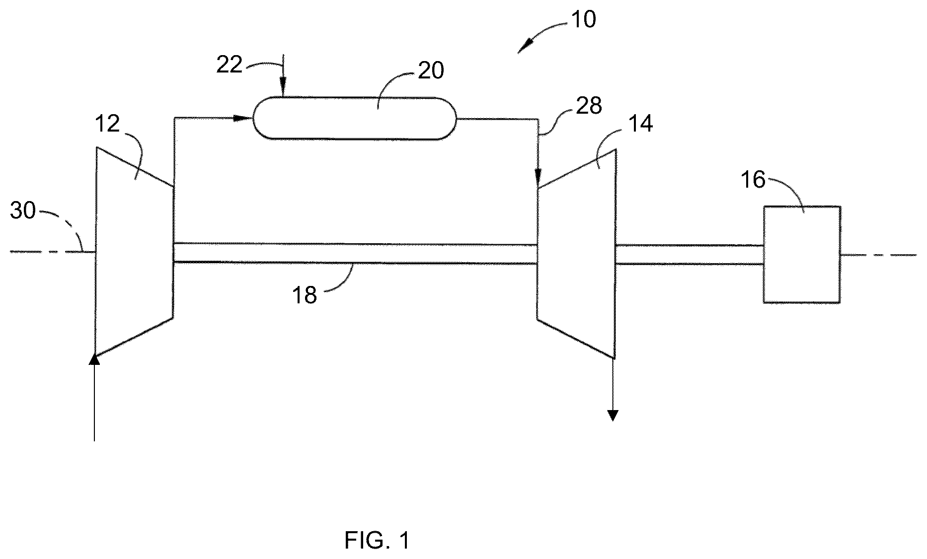
is schematic view of a gas turbine engine;
is a perspective view of a turbine blade in accordance with the teachings of the present disclosure for use in a gas turbine engine such as that shown in ;
is a side view of the turbine blade of , illustrating a plurality of airfoil cooling passages within the turbine blade in accordance with the teachings of the present disclosure;
is a side view of a portion of the turbine blade of , illustrating the airfoil cooling passages and a plurality of blade tip cooling apertures in accordance with the teachings of the present disclosure;
is a flow chart of a method of modifying a turbine blade in accordance with the teachings of the present disclosure;
is a side view of a portion of a turbine blade before being modified by the method of ;
is a side view of a portion of the turbine blade of illustrating a section of the turbine blade being removed as set forth in the method of ; and
is a side view of a portion of the turbine blade of illustrating a replacement section of the turbine blade for replacing the removed section as set forth in the method of .
The drawings described herein are for illustration purposes only and are not intended to limit the scope of the present disclosure in any way.
DETAILED DESCRIPTION
The following description is merely exemplary in nature and is not intended to limit the present disclosure, application, or uses. It should be understood that throughout the drawings, corresponding reference numerals indicate like or corresponding parts and features.
Referring to , an example gas turbine engine 10 is illustrated in schematic form. The gas turbine engine 10 can be any suitable type of turbine engine including, but not limited to, 6FA, 7FA, or 9FA type engines and their variants commercially available (e.g., 7FA.03, 7FA+e, 7FA+ Enhanced, MS7241FA, and PG7241 FA), such as from General Electric Company, Greenville, South Carolina. Generally, the gas turbine engine 10 includes a compressor 12 , a turbine 14 , and a combustor 20 . In the example provided, the gas turbine engine 10 is drivingly coupled to an electric generator 16 , though other configurations can be used, such as a gas turbine engine configured for providing thrust (e.g., an aircraft engine) for example.
The compressor 12 and the turbine 14 can be disposed about a common rotational axis 30 and are drivingly coupled together such as by a shaft 18 . The shaft 18 may be a single shaft or segmented by a plurality of shaft segments (not specifically shown). While the combustor 20 is shown schematically above the shaft 18 for ease of illustration, the combustor 20 may also be disposed about the axis 30 . The compressor 12 supplies compressed air to the combustor 20 . Fuel 22 is also supplied to the combustor 20 . The compressed air is mixed with the fuel 22 and combustion can take place in the combustor 20 . Combustion gasses 28 from the combustor 20 flow through and rotate the turbine 14 . The turbine 14 rotates the shaft 18 to rotate the compressor 12 and, in the example provided, to drive the electric generator 16 .
While the compressor 12 and turbine 14 are illustrated schematically, it is understood that the turbine 12 can include one or more compressor stages and the turbine 14 can include one or more turbine stages.
Referring to , an example turbine component 100 is illustrated. In the example provided, the turbine component 100 is a turbine rotor blade and is also referred to herein as the turbine rotor blade 100 or the turbine blade 100 . Although described herein with reference to a blade of a turbine rotor, the turbine component 100 may alternatively be a stator vane.
The turbine blade 100 is configured to be mounted on a rotor (not shown) of the turbine 14 ( ) of the turbine engine 10 ( ) such that the turbine blade 100 rotates about the rotational axis 30 in a rotational direction 18 and the main airflow through the turbine 14 ( ) is generally along direction 22 , also referred to herein as the aft direction 22 . In , the axis 30 is illustrated for orientation purposes only and the distance from the axis 30 to the turbine blade 100 is not drawn to scale in .
The turbine blade 100 includes a root 110 , a platform 114 , a blade tip 106 , and an airfoil 118 . The root 110 includes a shank 108 and a dovetail 112 . The shank 108 extends radially inward (e.g., direction 30 ) from the platform 114 and the dovetail 112 extends radially inward from the shank 108 . The dovetail 112 is configured to couple the turbine blade 100 to the rotor (not shown). In the example provided, the dovetail 112 is a shape typically referred to as a fir tree and is configured to be received in a mating channel (not shown) of the rotor (not shown), though other configurations can be used.
The platform 114 is disposed at an interface between the shank 108 and a proximal end portion 122 of the airfoil 118 such that the airfoil 118 extends radially outward (i.e., in direction 26 ) from the proximal end portion 122 at the platform 114 to a distal end portion 126 at the blade tip 106 . The root 110 extends radially inward (i.e., in direction 30 ) from the platform 114 .
The airfoil 118 extends from a top surface 158 of the platform 114 that faces generally radially outward. The airfoil 118 has a leading edge 170 , a trailing edge 174 , a pressure side surface 178 , and a suction side surface 182 . The leading edge 170 generally faces in the forward direction 34 and the trailing edge 174 generally faces in the aft direction 22 . The suction side surface 182 is a convex curved shape that generally faces in the direction 42 and the pressure side surface 178 is a concave curved shape that generally faces in the direction 46 .
The leading edge 170 defines a plurality of leading edge cooling apertures 206 that permit cooling air to exit the airfoil 118 along the leading edge 170 , as described in greater detail below. The blade tip 106 defines a plurality of outward tip cooling apertures 208 and a plurality of pressure side tip cooling apertures 210 . The outward tip cooling apertures 208 permit cooing air to exit the airfoil 118 in the radially outward direction 26 through the blade tip 106 . In the example provided, the outward tip cooling apertures 208 permit the cooling air to exit the airfoil 118 into a recess 212 defined in the radially outward end of the turbine blade 100 .
The pressure side tip cooling apertures 210 are arranged to permit cooling air to exit the pressure side surface 178 of the airfoil 118 along a pressure side of the blade tip 106 . With additional reference to , the trailing edge 174 also defines at least one trailing edge cooling aperture 204 . In the example provided, the trailing edge cooling aperture 204 is a single, narrow slot that extends lengthwise substantially the entire length (in the radial directions 26 , 30 ) of the trailing edge 174 , though other configurations can be used, e.g., a plurality of discrete apertures spaced along the trailing edge 174 .
Referring to , the turbine blade 100 defines a plurality of internal cooling passages 214 , 216 in fluid communication with the cooling apertures 204 , 206 , 208 , and/or 210 ( ). The internal cooling passages 214 , 216 have inlets 218 , 220 , 222 , 224 located in the dovetail 112 configured to receive pressurized air from the rotor (not shown). While four inlets 218 , 220 , 222 , 224 are illustrated, other numbers of inlets can be used such as one inlet, two inlets, three inlets, or more than four inlets.
In the example provided, the cooling passage 214 includes a plenum chamber 226 in the shank 108 that receives cooling air from the inlets 218 and 220 . The plenum chamber 226 provides the air to a leg 230 of the cooling passage 214 that extends radially outward through the platform 114 into the airfoil 118 and extends to the distal end portion 126 of the airfoil 118 . At the distal end portion 126 of the airfoil 118 , the leg 230 is connected to a junction portion 238 of the cooling passage 214 , which can be curved or arcuate. The junction portion 238 directs the pressurized cooling air back radially inward to another leg 246 of the cooling passage 214 that extends radially inward toward the platform 114 . In the example provided, some of the outward cooling apertures 208 ( ) in the blade tip 106 may be open to the junction portion 238 .
The leg 246 extends from the distal end portion 126 to the proximal end portion 122 . The leg 246 is connected to another junction portion 252 of the cooling passage 214 that is located proximate the platform 114 and can be located fully or partially within the airfoil 118 , the platform 114 or the shank 108 . The junction portion 252 curves back up so that the pressurized cooling air is directed radially outward into another leg 258 of the cooling passage 214 . The leg 258 extends radially outward toward the distal end portion 126 . In the example provided, the leg 258 extends fully to the blade tip 106 and is open to the leading edge cooling apertures 206 ( ) and may also be open to some of the outward cooling apertures 208 ( ) at the blade tip 106 , and may also be open to some of the pressure side cooling apertures 210 ( ), though other configurations can be used. As such, the legs 230 , 246 , 258 and junction portions 238 , 252 define a cooling passage having a serpentine path through a forward section of the turbine blade 100 . In the example provided, an additional passageway 262 can optionally connect directly from the plenum chamber 226 to the arcuate portion 252 .
In the example provided, the aft cooling passage 216 similarly includes a second plenum chamber 264 that receives air from the inlets 222 , 224 and provides the air to a first leg 268 of the aft cooling passage 216 that extends radially outward through the platform 114 into the airfoil 118 and extends to the distal end portion 126 of the airfoil 118 . At the distal end portion 126 of the airfoil 118 , the first leg 268 is connected to a first junction portion 274 of the aft cooling passage 216 , which can be curved or arcuate. The first junction portion 274 directs the pressurized cooling air back radially inward to a second leg 270 of the cooling passage 216 that extends radially inward toward the platform 114 . In the example provided, some of the outward cooling apertures 208 ( ) in the blade tip 106 may be open to the first junction portion 274 .
The second leg 270 extends from the distal end portion 126 to the proximal end portion 122 . The second leg 270 is connected to a second junction portion 276 of the cooling passage 216 that is located proximate the platform 114 and can be located fully or partially within the airfoil 118 , the platform 114 , or the shank 108 . The second junction portion 276 curves back up so that the pressurized cooling air is directed radially outward into a third leg 272 of the cooling passage 216 . The third leg 272 extends radially outward toward the distal end portion 126 . In the example provided, the third leg 272 extends fully to the blade tip 106 and is open to the trailing edge aperture(s) 204 and may be open to some of the outward cooling apertures 208 ( ) at the blade tip 106 , and may also be open to some of the pressure side cooling apertures 210 ( ), though other configurations can be used. As such, the first, second, and third legs 268 , 270 , 272 and the first and second junction portions 274 , 276 define a cooling passage having a serpentine path through an aft section of the turbine blade 100 . In the example provided, an additional passageway 278 can optionally connect directly from the plenum chamber 264 to the arcuate portion 252 .
With additional reference to , the distal end portion 126 and blade tip 106 of the turbine blade 100 are illustrated in greater detail. The pressure side cooling apertures 210 are spaced along the blade tip 106 between the leading edge 170 and the trailing edge 174 . In and as used herein, the pressure side cooling apertures are collectively indicated with the reference number 210 and the first eight of the pressure side cooling apertures 210 are individually identified with a suffix letter, e.g., 210 a , 210 b , 210 c , 210 d , 210 e , 210 f , 210 g , 210 h . The aftmost pressure side cooling apertures 210 (e.g., 210 a - 210 h ) overlap in the axial direction 22 , 34 with the third leg 272 and, in the example provided, are radially outward of the third leg 272 . At least one of these aftmost pressure side cooling apertures 270 is connected to a plenum 410 defined by the turbine blade 100 . The plenum 410 is connected directly to or forms a portion of the first junction portion 274 . As such pressurized cooling air can flow from the first junction portion 274 through the plenum 410 to at least some of the pressure side cooling apertures 210 that are axially aftward of at least a portion of the third leg 272 . In the example provided, all of the pressure side cooling apertures 210 are radially inward of the recess 212 , though other configurations can be used.
In the example provided, the turbine blade 100 has more than eight of the pressure side cooling passages 210 and, starting at the trailing edge 174 , at least one of the first eight pressure side cooling apertures 210 is connected to the plenum 410 to receive pressurized cooling air therefrom. In the example provided, the first four (i.e., four aftmost) pressure side cooling apertures 210 a - 210 d are connected to the third leg 272 to receive pressurized cooling air therefrom and the next four pressure side cooling apertures 210 e - 210 h are connected to the plenum 410 , though other configurations can be used such as more or less of the pressure side cooling apertures 210 being connected to the third leg 272 or plenum 410 .
Since the pressure of the pressurized cooling fluid decreases as it flows through the cooling passage 216 , these aftward pressure side cooling apertures 210 (e.g., 210 e - 210 h ) that are connected to the plenum 410 can receive cooling air at a higher pressure than if similarly located cooling apertures were connected to the third leg 272 .
In the example provided, the pressure side cooling apertures 210 are disposed in a single row along the pressure side surface 178 at the blade tip 106 , though other configurations can be used.
In the example provided, the plenum 410 extends from the first junction portion 274 in the axial aftward direction 22 to overlap axially a portion of the third leg 272 such that at least part of the plenum 410 can be radially outward of the portion of the third leg 272 . In the example provided, the plenum 410 does not overlap the entire third leg 272 . In an alternative configuration, not specifically shown, the plenum 410 may overlap more or less of the third leg 272 than shown in the example of , including the entire third leg 272 . The plenum 410 may also be connected to one or more of the outward cooling apertures 208 ( ). In the example provided, the plenum 410 is not directly connected to the third leg 272 . One or more of the pressure side cooling apertures 210 that are connected to the plenum 410 may optionally be aftward of the plenum 410 .
Returning to , the airfoil 118 may have any suitable airfoil shape. In one configuration, the airfoil 118 has a profile substantially in accordance with Cartesian coordinate values of X, Y, and Z of a pressure side as set forth in Table I. In another configuration, the airfoil 118 has a profile substantially in accordance with Cartesian coordinate values of X, Y, and Z of a suction side as set forth in Table I. In yet another configuration, the airfoil 118 has a profile substantially in accordance with Cartesian coordinate values of X, Y, and Z of a pressure side and a suction side as set forth in Table I.
In Table I, the Cartesian coordinate values of X, Y, and Z are such that Z is expressed as a percentage of the airfoil's span and the X and Y values are the dimensions in inches of the airfoil's nominal shape. In the example provided, the table is based on a nominal airfoil span of 6.308 inches, though other spans can be used. At each Z value, the X and Y coordinates describe the airfoil's cross-section profile shape, with the profile shapes joined by smooth continuous splines to form a complete 3-dimensional airfoil (i.e., airfoil 118 ). By expressing the Z value as a percentage of span and allowing the X and Y values to be scaled (or multiplied) by any appropriate constant number, an airfoil of any chord length can be used in any flowpath annulus by multiplying the Z values by the airfoil's spanwise height and the X and Y values by the desired chord length.
As such, the airfoil comprises a nominal airfoil profile substantially in accordance with Cartesian coordinate values of X, Y, and Z as set forth in Table I, wherein the values of X and Y are distances in inches which, when connected by smooth continuing arcs, define airfoil profile sections at each value of Z which is a distance expressed as a percentage of a span of the nominal airfoil profile, the airfoil profile sections at the Z distances being joined smoothly with one another to form a complete airfoil shape.
TABLE I
Points per A-Dimension Span
Sections Section (in.) (in.)
10 112 40.794998 6.308002
SECTION 1 Suction Side
Pt. X Y Z %-Span
1 −2.352958 −0.707216 −0.324997 −0.051521
2 −2.359088 −0.703116 −0.324997 −0.051521
3 −2.365098 −0.698846 −0.324997 −0.051521
4 −2.376738 −0.689776 −0.324997 −0.051521
5 −2.387798 −0.680016 −0.324997 −0.051521
6 −2.403248 −0.664176 −0.324997 −0.051521
7 −2.421508 −0.641006 −0.324997 −0.051521
8 −2.440238 −0.609246 −0.324997 −0.051521
9 −2.458108 −0.560806 −0.324997 −0.051521
10 −2.466418 −0.494956 −0.324997 −0.051521
11 −2.461968 −0.413946 −0.324997 −0.051521
12 −2.444218 −0.319716 −0.324997 −0.051521
13 −2.413138 −0.213546 −0.324997 −0.051521
14 −2.369238 −0.096096 −0.324997 −0.051521
15 −2.313388 0.032424 −0.324997 −0.051521
16 −2.245578 0.171672 −0.324997 −0.051521
17 −2.163818 0.320302 −0.324997 −0.051521
18 −2.064448 0.475622 −0.324997 −0.051521
19 −1.951228 0.630392 −0.324997 −0.051521
20 −1.817718 0.787952 −0.324997 −0.051521
21 −1.664338 0.93702 −0.324997 −0.051521
22 −1.496738 1.0699 −0.324997 −0.051521
23 −1.309058 1.18709 −0.324997 −0.051521
24 −1.108528 1.28061 −0.324997 −0.051521
25 −0.897948 1.34851 −0.324997 −0.051521
26 −0.679088 1.381068 −0.324997 −0.051521
27 −0.458088 1.370448 −0.324997 −0.051521
28 −0.24107 1.327298 −0.324997 −0.051521
29 −0.03813 1.239138 −0.324997 −0.051521
30 0.14515 1.115168 −0.324997 −0.051521
31 0.31105 0.968768 −0.324997 −0.051521
32 0.4617 0.806708 −0.324997 −0.051521
33 0.59958 0.633658 −0.324997 −0.051521
34 0.728548 0.453868 −0.324997 −0.051521
35 0.849908 0.268858 −0.324997 −0.051521
36 0.965488 0.080188 −0.324997 −0.051521
37 1.070128 −0.106352 −0.324997 −0.051521
38 1.165808 −0.297652 −0.324997 −0.051521
39 1.251688 −0.485462 −0.324997 −0.051521
40 1.326548 −0.662002 −0.324997 −0.051521
41 1.396998 −0.8324 −0.324997 −0.051521
42 1.459998 −0.9899 −0.324997 −0.051521
43 1.516258 −1.13421 −0.324997 −0.051521
44 1.563818 −1.26602 −0.324997 −0.051521
45 1.604538 −1.38461 −0.324997 −0.051521
46 1.640498 −1.48923 −0.324997 −0.051521
47 1.671198 −1.58007 −0.324997 −0.051521
48 1.696178 −1.65725 −0.324997 −0.051521
49 1.716968 −1.72029 −0.324997 −0.051521
50 1.730228 −1.77019 −0.324997 −0.051521
51 1.732218 −1.80701 −0.324997 −0.051521
52 1.725418 −1.83572 −0.324997 −0.051521
53 1.713728 −1.8545 −0.324997 −0.051521
54 1.703438 −1.86507 −0.324997 −0.051521
55 1.691658 −1.87394 −0.324997 −0.051521
56 1.685268 −1.87763 −0.324997 −0.051521
SECTION 1 Pressure Side
Pt. X Y Z %-Span
57 1.678609 −1.88081 −0.324997 −0.051521
58 1.673869 −1.88279 −0.324997 −0.051521
59 1.66902 −1.88449 −0.324997 −0.051521
60 1.659019 −1.88692 −0.324997 −0.051521
61 1.64878 −1.88784 −0.324997 −0.051521
62 1.63336 −1.8876 −0.324997 −0.051521
63 1.613129 −1.88392 −0.324997 −0.051521
64 1.589849 −1.87301 −0.324997 −0.051521
65 1.56197 −1.85025 −0.324997 −0.051521
66 1.53364 −1.81366 −0.324997 −0.051521
67 1.503489 −1.76582 −0.324997 −0.051521
68 1.46842 −1.70892 −0.324997 −0.051521
69 1.42853 −1.64292 −0.324997 −0.051521
70 1.3846 −1.56735 −0.324997 −0.051521
71 1.335379 −1.48297 −0.324997 −0.051521
72 1.27914 −1.39081 −0.324997 −0.051521
73 1.21543 −1.29119 −0.324997 −0.051521
74 1.1445 −1.18399 −0.324997 −0.051521
75 1.06877 −1.07384 −0.324997 −0.051521
76 0.98391 −0.957552 −0.324997 −0.051521
77 0.89241 −0.839832 −0.324997 −0.051521
78 0.79729 −0.725012 −0.324997 −0.051521
79 0.69403 −0.610432 −0.324997 −0.051521
80 0.58567 −0.500672 −0.324997 −0.051521
81 0.4722 −0.396192 −0.324997 −0.051521
82 0.35288 −0.298452 −0.324997 −0.051521
83 0.22735 −0.208822 −0.324997 −0.051521
84 0.09514 −0.12939 −0.324997 −0.051521
85 −0.04307 −0.06091 −0.324997 −0.051521
86 −0.18614 −0.00327 −0.324997 −0.051521
87 −0.334378 0.03933 −0.324997 −0.051521
88 −0.486888 0.06235 −0.324997 −0.051521
89 −0.641118 0.0645 −0.324997 −0.051521
90 −0.794348 0.046902 −0.324997 −0.051521
91 −0.945098 0.014262 −0.324997 −0.051521
92 −1.092138 −0.032318 −0.324997 −0.051521
93 −1.230308 −0.088338 −0.324997 −0.051521
94 −1.363608 −0.155146 −0.324997 −0.051521
95 −1.486648 −0.229886 −0.324997 −0.051521
96 −1.597378 −0.304776 −0.324997 −0.051521
97 −1.701638 −0.379946 −0.324997 −0.051521
98 −1.794258 −0.453466 −0.324997 −0.051521
99 −1.875888 −0.524126 −0.324997 −0.051521
100 −1.948998 −0.588916 −0.324997 −0.051521
101 −2.01421 −0.647116 −0.324997 −0.051521
102 −2.07251 −0.697606 −0.324997 −0.051521
103 −2.130908 −0.730096 −0.324997 −0.051521
104 −2.185698 −0.744116 −0.324997 −0.051521
105 −2.231928 −0.746146 −0.324997 −0.051521
106 −2.267648 −0.741716 −0.324997 −0.051521
107 −2.292568 −0.735406 −0.324997 −0.051521
108 −2.311938 −0.728496 −0.324997 −0.051521
109 −2.326038 −0.722246 −0.324997 −0.051521
110 −2.335208 −0.717606 −0.324997 −0.051521
111 −2.344188 −0.712586 −0.324997 −0.051521
112 −2.348598 −0.709936 −0.324997 −0.051521
SECTION 2 Suction Side
Pt. X Y Z %-Span
1 −2.33291 −0.64703 0.026001 0.004122
2 −2.33895 −0.64303 0.026001 0.004122
3 −2.34486 −0.63885 0.026001 0.004122
4 −2.35628 −0.62994 0.026001 0.004122
5 −2.36711 −0.62033 0.026001 0.004122
6 −2.38217 −0.60468 0.026001 0.004122
7 −2.39983 −0.58172 0.026001 0.004122
8 −2.41765 −0.55021 0.026001 0.004122
9 −2.43371 −0.50214 0.026001 0.004122
10 −2.44171 −0.43747 0.026001 0.004122
11 −2.43883 −0.35788 0.026001 0.004122
12 −2.42297 −0.2651 0.026001 0.004122
13 −2.39317 −0.16066 0.026001 0.004122
14 −2.34956 −0.04556 0.026001 0.004122
15 −2.29278 0.07974 0.026001 0.004122
16 −2.22318 0.21492 0.026001 0.004122
17 −2.13952 0.35892 0.026001 0.004122
18 −2.03871 0.50926 0.026001 0.004122
19 −1.92403 0.65854 0.026001 0.004122
20 −1.78919 0.80993 0.026001 0.004122
21 −1.63515 0.95262 0.026001 0.004122
22 −1.46727 1.07873 0.026001 0.004122
23 −1.28004 1.18885 0.026001 0.004122
24 −1.08063 1.27497 0.026001 0.004122
25 −0.87167 1.33426 0.026001 0.004122
26 −0.65582 1.35849 0.026001 0.004122
27 −0.43933 1.34071 0.026001 0.004122
28 −0.22849 1.2885 0.026001 0.004122
29 −0.03224 1.1954 0.026001 0.004122
30 0.14479 1.06955 0.026001 0.004122
31 0.30499 0.92285 0.026001 0.004122
32 0.45081 0.76186 0.026001 0.004122
33 0.58514 0.59117 0.026001 0.004122
34 0.71112 0.41422 0.026001 0.004122
35 0.82994 0.23239 0.026001 0.004122
36 0.94297 0.0469 0.026001 0.004122
37 1.04554 −0.13631 0.026001 0.004122
38 1.14059 −0.32353 0.026001 0.004122
39 1.22624 −0.50728 0.026001 0.004122
40 1.3012 −0.67997 0.026001 0.004122
41 1.37079 −0.84707 0.026001 0.004122
42 1.43296 −1.00156 0.026001 0.004122
43 1.4884 −1.14313 0.026001 0.004122
44 1.53615 −1.27215 0.026001 0.004122
45 1.57737 −1.38813 0.026001 0.004122
46 1.61344 −1.49057 0.026001 0.004122
47 1.64439 −1.57946 0.026001 0.004122
48 1.66958 −1.65502 0.026001 0.004122
49 1.69047 −1.71674 0.026001 0.004122
50 1.70427 −1.76551 0.026001 0.004122
51 1.7075 −1.80157 0.026001 0.004122
52 1.70253 −1.8301 0.026001 0.004122
53 1.69282 −1.84953 0.026001 0.004122
54 1.68358 −1.86068 0.026001 0.004122
55 1.67276 −1.8703 0.026001 0.004122
56 1.66681 −1.87443 0.026001 0.004122
SECTION 2 Pressure Side
Pt. X Y Z %-Span
57 1.66056 −1.87808 0.026001 0.004122
58 1.65601 −1.88034 0.026001 0.004122
59 1.65133 −1.88235 0.026001 0.004122
60 1.64169 −1.88558 0.026001 0.004122
61 1.63175 −1.88773 0.026001 0.004122
62 1.61653 −1.88884 0.026001 0.004122
63 1.59633 −1.88644 0.026001 0.004122
64 1.57254 −1.87748 0.026001 0.004122
65 1.54485 −1.8551 0.026001 0.004122
66 1.51721 −1.81862 0.026001 0.004122
67 1.4873 −1.77134 0.026001 0.004122
68 1.45261 −1.71507 0.026001 0.004122
69 1.41349 −1.64958 0.026001 0.004122
70 1.36964 −1.57507 0.026001 0.004122
71 1.32031 −1.49199 0.026001 0.004122
72 1.26437 −1.40102 0.026001 0.004122
73 1.20129 −1.30252 0.026001 0.004122
74 1.13092 −1.19663 0.026001 0.004122
75 1.05568 −1.0879 0.026001 0.004122
76 0.97156 −0.97301 0.026001 0.004122
77 0.88089 −0.8567 0.026001 0.004122
78 0.78663 −0.74327 0.026001 0.004122
79 0.68484 −0.62963 0.026001 0.004122
80 0.5786 −0.52014 0.026001 0.004122
81 0.46761 −0.41546 0.026001 0.004122
82 0.35106 −0.31701 0.026001 0.004122
83 0.22865 −0.22594 0.026001 0.004122
84 0.10005 −0.14387 0.026001 0.004122
85 −0.03446 −0.07186 0.026001 0.004122
86 −0.17416 −0.01055 0.026001 0.004122
87 −0.31919 0.03679 0.026001 0.004122
88 −0.46885 0.06645 0.026001 0.004122
89 −0.62105 0.07699 0.026001 0.004122
90 −0.77338 0.06846 0.026001 0.004122
91 −0.92392 0.04373 0.026001 0.004122
92 −1.07126 0.00415 0.026001 0.004122
93 −1.20974 −0.04658 0.026001 0.004122
94 −1.34337 −0.10899 0.026001 0.004122
95 −1.46724 −0.17922 0.026001 0.004122
96 −1.5786 −0.25051 0.026001 0.004122
97 −1.6829 −0.3232 0.026001 0.004122
98 −1.77566 −0.39446 0.026001 0.004122
99 −1.85759 −0.46296 0.026001 0.004122
100 −1.93083 −0.52599 0.026001 0.004122
101 −1.99656 −0.58214 0.026001 0.004122
102 −2.05647 −0.62937 0.026001 0.004122
103 −2.11372 −0.66243 0.026001 0.004122
104 −2.16703 −0.67936 0.026001 0.004122
105 −2.21264 −0.68318 0.026001 0.004122
106 −2.24809 −0.67988 0.026001 0.004122
107 −2.27287 −0.67418 0.026001 0.004122
108 −2.29215 −0.66769 0.026001 0.004122
109 −2.30618 −0.66171 0.026001 0.004122
110 −2.3153 −0.6572 0.026001 0.004122
111 −2.32422 −0.65231 0.026001 0.004122
112 −2.32859 −0.64971 0.026001 0.004122
SECTION 3 Suction Side
Pt. X Y Z %-Span
1 −2.28286 −0.49833 0.883003 0.139981
2 −2.28867 −0.49456 0.883003 0.139981
3 −2.29435 −0.49059 0.883003 0.139981
4 −2.30524 −0.48203 0.883003 0.139981
5 −2.31539 −0.47261 0.883003 0.139981
6 −2.32899 −0.4569 0.883003 0.139981
7 −2.34392 −0.43356 0.883003 0.139981
8 −2.35819 −0.402 0.883003 0.139981
9 −2.37142 −0.35536 0.883003 0.139981
10 −2.3793 −0.29352 0.883003 0.139981
11 −2.37809 −0.21734 0.883003 0.139981
12 −2.36426 −0.12837 0.883003 0.139981
13 −2.33597 −0.0284 0.883003 0.139981
14 −2.29225 0.08094 0.883003 0.139981
15 −2.23305 0.19847 0.883003 0.139981
16 −2.15917 0.32376 0.883003 0.139981
17 −2.07063 0.4562 0.883003 0.139981
18 −1.96579 0.59402 0.883003 0.139981
19 −1.84738 0.7297 0.883003 0.139981
20 −1.70896 0.86553 0.883003 0.139981
21 −1.55291 0.99201 0.883003 0.139981
22 −1.38433 1.10122 0.883003 0.139981
23 −1.19805 1.19329 0.883003 0.139981
24 −1.00127 1.26004 0.883003 0.139981
25 −0.79684 1.29727 0.883003 0.139981
26 −0.58906 1.29896 0.883003 0.139981
27 −0.3846 1.26189 0.883003 0.139981
28 −0.1904 1.18796 0.883003 0.139981
29 −0.01154 1.0822 0.883003 0.139981
30 0.15006 0.95158 0.883003 0.139981
31 0.29654 0.8042 0.883003 0.139981
32 0.43065 0.64548 0.883003 0.139981
33 0.55603 0.47978 0.883003 0.139981
34 0.67476 0.30925 0.883003 0.139981
35 0.78754 0.13473 0.883003 0.139981
36 0.89448 −0.04343 0.883003 0.139981
37 0.99172 −0.21919 0.883003 0.139981
38 1.08395 −0.39763 0.883003 0.139981
39 1.16827 −0.57228 0.883003 0.139981
40 1.24262 −0.7363 0.883003 0.139981
41 1.31046 −0.89562 0.883003 0.139981
42 1.37106 −1.04295 0.883003 0.139981
43 1.42491 −1.17807 0.883003 0.139981
44 1.47259 −1.30073 0.883003 0.139981
45 1.51439 −1.41081 0.883003 0.139981
46 1.55054 −1.50821 0.883003 0.139981
47 1.58163 −1.59272 0.883003 0.139981
48 1.6072 −1.66449 0.883003 0.139981
49 1.62832 −1.72314 0.883003 0.139981
50 1.64197 −1.76966 0.883003 0.139981
51 1.64563 −1.8041 0.883003 0.139981
52 1.6408 −1.83138 0.883003 0.139981
53 1.63174 −1.85008 0.883003 0.139981
54 1.6234 −1.86114 0.883003 0.139981
55 1.61345 −1.87078 0.883003 0.139981
56 1.60795 −1.87499 0.883003 0.139981
SECTION 3 Pressure Side
Pt. X Y Z %-Span
57 1.60214 −1.87876 0.883003 0.139981
58 1.59782 −1.88116 0.883003 0.139981
59 1.59339 −1.88333 0.883003 0.139981
60 1.58418 −1.8869 0.883003 0.139981
61 1.57463 −1.88943 0.883003 0.139981
62 1.55992 −1.89122 0.883003 0.139981
63 1.54022 −1.88975 0.883003 0.139981
64 1.51692 −1.88159 0.883003 0.139981
65 1.49148 −1.85817 0.883003 0.139981
66 1.46605 −1.82172 0.883003 0.139981
67 1.43743 −1.77554 0.883003 0.139981
68 1.40436 −1.72051 0.883003 0.139981
69 1.36651 −1.65683 0.883003 0.139981
70 1.32319 −1.5849 0.883003 0.139981
71 1.27414 −1.50491 0.883003 0.139981
72 1.21915 −1.41697 0.883003 0.139981
73 1.15765 −1.32147 0.883003 0.139981
74 1.08883 −1.21896 0.883003 0.139981
75 1.01506 −1.11385 0.883003 0.139981
76 0.93297 −1.00257 0.883003 0.139981
77 0.84468 −0.88979 0.883003 0.139981
78 0.75299 −0.77976 0.883003 0.139981
79 0.65495 −0.66868 0.883003 0.139981
80 0.55378 −0.56043 0.883003 0.139981
81 0.44861 −0.45606 0.883003 0.139981
82 0.33876 −0.35664 0.883003 0.139981
83 0.22398 −0.26295 0.883003 0.139981
84 0.10403 −0.17598 0.883003 0.139981
85 −0.02157 −0.09739 0.883003 0.139981
86 −0.15297 −0.02893 0.883003 0.139981
87 −0.28979 0.02794 0.883003 0.139981
88 −0.43149 0.07123 0.883003 0.139981
89 −0.577 0.09911 0.883003 0.139981
90 −0.72477 0.1099 0.883003 0.139981
91 −0.87279 0.10322 0.883003 0.139981
92 −1.01916 0.08024 0.883003 0.139981
93 −1.15743 0.04289 0.883003 0.139981
94 −1.29137 −0.00783 0.883003 0.139981
95 −1.41647 −0.06676 0.883003 0.139981
96 −1.52879 −0.12899 0.883003 0.139981
97 −1.63319 −0.19491 0.883003 0.139981
98 −1.72626 −0.26003 0.883003 0.139981
99 −1.80883 −0.3228 0.883003 0.139981
100 −1.88243 −0.38101 0.883003 0.139981
101 −1.9494 −0.43164 0.883003 0.139981
102 −2.01153 −0.47199 0.883003 0.139981
103 −2.06887 −0.50087 0.883003 0.139981
104 −2.12061 −0.51746 0.883003 0.139981
105 −2.16448 −0.52456 0.883003 0.139981
106 −2.19905 −0.52522 0.883003 0.139981
107 −2.22354 −0.52203 0.883003 0.139981
108 −2.24263 −0.51697 0.883003 0.139981
109 −2.25656 −0.51192 0.883003 0.139981
110 −2.26558 −0.50789 0.883003 0.139981
111 −2.27435 −0.50335 0.883003 0.139981
112 −2.27864 −0.5009 0.883003 0.139981
SECTION 4 Suction Side
Pt. X Y Z %-Span
1 −2.22479 −0.32534 1.883003 0.298510
2 −2.23003 −0.32139 1.883003 0.298510
3 −2.23511 −0.31722 1.883003 0.298510
4 −2.24472 −0.30827 1.883003 0.298510
5 −2.25356 −0.29855 1.883003 0.298510
6 −2.26533 −0.28275 1.883003 0.298510
7 −2.27823 −0.25987 1.883003 0.298510
8 −2.29018 −0.22928 1.883003 0.298510
9 −2.30034 −0.18444 1.883003 0.298510
10 −2.30487 −0.1255 1.883003 0.298510
11 −2.30045 −0.05339 1.883003 0.298510
12 −2.28414 0.03041 1.883003 0.298510
13 −2.25355 0.12406 1.883003 0.298510
14 −2.2069 0.2255 1.883003 0.298510
15 −2.14401 0.33329 1.883003 0.298510
16 −2.06553 0.4467 1.883003 0.298510
17 −1.97195 0.56529 1.883003 0.298510
18 −1.8625 0.68769 1.883003 0.298510
19 −1.74001 0.80666 1.883003 0.298510
20 −1.59792 0.92341 1.883003 0.298510
21 −1.43961 1.02931 1.883003 0.298510
22 −1.2708 1.11752 1.883003 0.298510
23 −1.08619 1.18638 1.883003 0.298510
24 −0.89346 1.22733 1.883003 0.298510
25 −0.69663 1.23655 1.883003 0.298510
26 −0.50133 1.2105 1.883003 0.298510
27 −0.31438 1.14827 1.883003 0.298510
28 −0.14151 1.05372 1.883003 0.298510
29 0.01691 0.93656 1.883003 0.298510
30 0.1615 0.80271 1.883003 0.298510
31 0.29342 0.65635 1.883003 0.298510
32 0.41515 0.50142 1.883003 0.298510
33 0.53012 0.34141 1.883003 0.298510
34 0.64067 0.17831 1.883003 0.298510
35 0.7465 0.0121 1.883003 0.298510
36 0.84634 −0.15776 1.883003 0.298510
37 0.93746 −0.32502 1.883003 0.298510
38 1.02464 −0.49437 1.883003 0.298510
39 1.10588 −0.65935 1.883003 0.298510
40 1.17754 −0.81435 1.883003 0.298510
41 1.24349 −0.96472 1.883003 0.298510
42 1.3029 −1.10361 1.883003 0.298510
43 1.35581 −1.23098 1.883003 0.298510
44 1.40291 −1.34654 1.883003 0.298510
45 1.44403 −1.45034 1.883003 0.298510
46 1.47961 −1.54221 1.883003 0.298510
47 1.51027 −1.6219 1.883003 0.298510
48 1.53565 −1.68954 1.883003 0.298510
49 1.55675 −1.74476 1.883003 0.298510
50 1.5697 −1.78887 1.883003 0.298510
51 1.57134 −1.82167 1.883003 0.298510
52 1.56436 −1.84699 1.883003 0.298510
53 1.55313 −1.86318 1.883003 0.298510
54 1.5436 −1.87223 1.883003 0.298510
55 1.53292 −1.87988 1.883003 0.298510
56 1.52719 −1.88309 1.883003 0.298510
SECTION 4 Pressure Side
Pt. X Y Z %-Span
57 1.52125 −1.88588 1.883003 0.298510
58 1.51682 −1.88764 1.883003 0.298510
59 1.5123 −1.88916 1.883003 0.298510
60 1.50305 −1.89148 1.883003 0.298510
61 1.49362 −1.89281 1.883003 0.298510
62 1.47932 −1.89296 1.883003 0.298510
63 1.46054 −1.88967 1.883003 0.298510
64 1.43953 −1.87843 1.883003 0.298510
65 1.41707 −1.85375 1.883003 0.298510
66 1.39292 −1.8183 1.883003 0.298510
67 1.36569 −1.7735 1.883003 0.298510
68 1.33389 −1.72032 1.883003 0.298510
69 1.29711 −1.65901 1.883003 0.298510
70 1.25489 −1.58985 1.883003 0.298510
71 1.20728 −1.51282 1.883003 0.298510
72 1.15405 −1.42805 1.883003 0.298510
73 1.09445 −1.33604 1.883003 0.298510
74 1.02777 −1.23729 1.883003 0.298510
75 0.95641 −1.13597 1.883003 0.298510
76 0.87727 −1.02852 1.883003 0.298510
77 0.79248 −0.91935 1.883003 0.298510
78 0.70484 −0.81247 1.883003 0.298510
79 0.61173 −0.70394 1.883003 0.298510
80 0.51619 −0.59756 1.883003 0.298510
81 0.41729 −0.49429 1.883003 0.298510
82 0.3148 −0.39458 1.883003 0.298510
83 0.2084 −0.29905 1.883003 0.298510
84 0.09733 −0.209 1.883003 0.298510
85 −0.01947 −0.12652 1.883003 0.298510
86 −0.14212 −0.05301 1.883003 0.298510
87 −0.26987 0.01122 1.883003 0.298510
88 −0.40233 0.06507 1.883003 0.298510
89 −0.53933 0.10602 1.883003 0.298510
90 −0.67987 0.13234 1.883003 0.298510
91 −0.82249 0.14267 1.883003 0.298510
92 −0.96535 0.13659 1.883003 0.298510
93 −1.10181 0.11462 1.883003 0.298510
94 −1.23523 0.07848 1.883003 0.298510
95 −1.36047 0.03238 1.883003 0.298510
96 −1.47309 −0.01934 1.883003 0.298510
97 −1.5777 −0.07639 1.883003 0.298510
98 −1.67107 −0.13382 1.883003 0.298510
99 −1.75424 −0.18952 1.883003 0.298510
100 −1.82866 −0.24112 1.883003 0.298510
101 −1.89671 −0.2851 1.883003 0.298510
102 −1.95968 −0.31896 1.883003 0.298510
103 −2.01743 −0.34139 1.883003 0.298510
104 −2.06881 −0.35188 1.883003 0.298510
105 −2.11157 −0.35523 1.883003 0.298510
106 −2.14491 −0.35393 1.883003 0.298510
107 −2.16843 −0.3501 1.883003 0.298510
108 −2.18678 −0.34491 1.883003 0.298510
109 −2.20007 −0.33963 1.883003 0.298510
110 −2.20862 −0.33542 1.883003 0.298510
111 −2.21688 −0.33066 1.883003 0.298510
112 −2.22088 −0.32807 1.883003 0.298510
SECTION 5 Suction Side
Pt. X Y Z %-Span
1 −2.15278 −0.11084 3.123001 0.495086
2 −2.15714 −0.10654 3.123001 0.495086
3 −2.16134 −0.10209 3.123001 0.495086
4 −2.16923 −0.09273 3.123001 0.495086
5 −2.17643 −0.08283 3.123001 0.495086
6 −2.18593 −0.06712 3.123001 0.495086
7 −2.19618 −0.04488 3.123001 0.495086
8 −2.20529 −0.01566 3.123001 0.495086
9 −2.21182 0.02668 3.123001 0.495086
10 −2.21079 0.08176 3.123001 0.495086
11 −2.19939 0.14812 3.123001 0.495086
12 −2.17714 0.22452 3.123001 0.495086
13 −2.14112 0.30897 3.123001 0.495086
14 −2.0893 0.3992 3.123001 0.495086
15 −2.02206 0.49409 3.123001 0.495086
16 −1.93965 0.59274 3.123001 0.495086
17 −1.84179 0.69395 3.123001 0.495086
18 −1.72786 0.79611 3.123001 0.495086
19 −1.60124 0.89252 3.123001 0.495086
20 −1.45543 0.9826 3.123001 0.495086
21 −1.29486 1.05826 3.123001 0.495086
22 −1.12636 1.11409 3.123001 0.495086
23 −0.94569 1.14694 3.123001 0.495086
24 −0.76211 1.15124 3.123001 0.495086
25 −0.58036 1.12507 3.123001 0.495086
26 −0.4059 1.06775 3.123001 0.495086
27 −0.24363 0.9818 3.123001 0.495086
28 −0.09387 0.87554 3.123001 0.495086
29 0.04407 0.75433 3.123001 0.495086
30 0.17123 0.62185 3.123001 0.495086
31 0.28845 0.4805 3.123001 0.495086
32 0.39769 0.3329 3.123001 0.495086
33 0.50153 0.18145 3.123001 0.495086
34 0.60213 0.02783 3.123001 0.495086
35 0.69842 −0.12853 3.123001 0.495086
36 0.78978 −0.28782 3.123001 0.495086
37 0.87435 −0.44389 3.123001 0.495086
38 0.95615 −0.60142 3.123001 0.495086
39 1.03241 −0.75491 3.123001 0.495086
40 1.10013 −0.89893 3.123001 0.495086
41 1.16313 −1.03838 3.123001 0.495086
42 1.22024 −1.16706 3.123001 0.495086
43 1.27159 −1.2849 3.123001 0.495086
44 1.31739 −1.3918 3.123001 0.495086
45 1.35747 −1.48783 3.123001 0.495086
46 1.39227 −1.5728 3.123001 0.495086
47 1.42224 −1.64651 3.123001 0.495086
48 1.44712 −1.70908 3.123001 0.495086
49 1.46817 −1.75998 3.123001 0.495086
50 1.48174 −1.80062 3.123001 0.495086
51 1.48365 −1.83117 3.123001 0.495086
52 1.47526 −1.85417 3.123001 0.495086
53 1.46432 −1.86892 3.123001 0.495086
54 1.4554 −1.8773 3.123001 0.495086
55 1.44537 −1.88433 3.123001 0.495086
56 1.44002 −1.88729 3.123001 0.495086
SECTION 5 Pressure Side
Pt. X Y Z %-Span
57 1.43446 −1.88986 3.123001 0.495086
58 1.43018 −1.89152 3.123001 0.495086
59 1.42581 −1.89296 3.123001 0.495086
60 1.41688 −1.89512 3.123001 0.495086
61 1.40777 −1.89631 3.123001 0.495086
62 1.39399 −1.89625 3.123001 0.495086
63 1.37594 −1.89279 3.123001 0.495086
64 1.35536 −1.88259 3.123001 0.495086
65 1.33191 −1.86058 3.123001 0.495086
66 1.30769 −1.82707 3.123001 0.495086
67 1.28131 −1.78396 3.123001 0.495086
68 1.25045 −1.73283 3.123001 0.495086
69 1.21472 −1.67391 3.123001 0.495086
70 1.17396 −1.60729 3.123001 0.495086
71 1.12807 −1.53304 3.123001 0.495086
72 1.07676 −1.45134 3.123001 0.495086
73 1.0195 −1.36253 3.123001 0.495086
74 0.95577 −1.26698 3.123001 0.495086
75 0.88793 −1.16867 3.123001 0.495086
76 0.81286 −1.06421 3.123001 0.495086
77 0.73287 −0.95767 3.123001 0.495086
78 0.65072 −0.85278 3.123001 0.495086
79 0.56373 −0.74588 3.123001 0.495086
80 0.47457 −0.64078 3.123001 0.495086
81 0.38273 −0.53802 3.123001 0.495086
82 0.28775 −0.43814 3.123001 0.495086
83 0.18923 −0.34177 3.123001 0.495086
84 0.08629 −0.25012 3.123001 0.495086
85 −0.02221 −0.16513 3.123001 0.495086
86 −0.1356 −0.08679 3.123001 0.495086
87 −0.25347 −0.01536 3.123001 0.495086
88 −0.37598 0.04778 3.123001 0.495086
89 −0.50333 0.10049 3.123001 0.495086
90 −0.63494 0.14139 3.123001 0.495086
91 −0.76995 0.16907 3.123001 0.495086
92 −0.90721 0.18158 3.123001 0.495086
93 −1.0404 0.17827 3.123001 0.495086
94 −1.17247 0.16072 3.123001 0.495086
95 −1.2976 0.13091 3.123001 0.495086
96 −1.41074 0.0926 3.123001 0.495086
97 −1.51619 0.04711 3.123001 0.495086
98 −1.61039 −0.00077 3.123001 0.495086
99 −1.69466 −0.04774 3.123001 0.495086
100 −1.77068 −0.09063 3.123001 0.495086
101 −1.84 −0.12662 3.123001 0.495086
102 −1.90389 −0.15243 3.123001 0.495086
103 −1.96192 −0.16654 3.123001 0.495086
104 −2.01235 −0.16992 3.123001 0.495086
105 −2.05346 −0.16561 3.123001 0.495086
106 −2.08422 −0.15624 3.123001 0.495086
107 −2.10496 −0.14636 3.123001 0.495086
108 −2.12065 −0.13679 3.123001 0.495086
109 −2.13184 −0.12875 3.123001 0.495086
110 −2.13904 −0.12304 3.123001 0.495086
111 −2.14601 −0.11706 3.123001 0.495086
112 −2.14942 −0.11398 3.123001 0.495086
SECTION 6 Suction Side
Pt. X Y Z %-Span
1 −2.08077 0.10366 4.363003 0.691662
2 −2.08456 0.10799 4.363003 0.691662
3 −2.08817 0.11247 4.363003 0.691662
4 −2.09489 0.12181 4.363003 0.691662
5 −2.10092 0.13161 4.363003 0.691662
6 −2.10865 0.14704 4.363003 0.691662
7 −2.11657 0.16865 4.363003 0.691662
8 −2.1228 0.19673 4.363003 0.691662
9 −2.12505 0.23694 4.363003 0.691662
10 −2.11973 0.28844 4.363003 0.691662
11 −2.10498 0.34998 4.363003 0.691662
12 −2.07819 0.41981 4.363003 0.691662
13 −2.03778 0.49606 4.363003 0.691662
14 −1.98284 0.57698 4.363003 0.691662
15 −1.91291 0.66099 4.363003 0.691662
16 −1.82744 0.74638 4.363003 0.691662
17 −1.7256 0.83086 4.363003 0.691662
18 −1.60688 0.91206 4.363003 0.691662
19 −1.47549 0.98356 4.363003 0.691662
20 −1.32623 1.04414 4.363003 0.691662
21 −1.16509 1.08738 4.363003 0.691662
22 −0.99969 1.10923 4.363003 0.691662
23 −0.82711 1.10649 4.363003 0.691662
24 −0.65706 1.07699 4.363003 0.691662
25 −0.49372 1.02124 4.363003 0.691662
26 −0.34128 0.94031 4.363003 0.691662
27 −0.20041 0.84059 4.363003 0.691662
28 −0.0696 0.72799 4.363003 0.691662
29 0.05166 0.60517 4.363003 0.691662
30 0.1645 0.47457 4.363003 0.691662
31 0.27034 0.33824 4.363003 0.691662
32 0.37018 0.19745 4.363003 0.691662
33 0.46544 0.05353 4.363003 0.691662
34 0.55732 −0.09258 4.363003 0.691662
35 0.64558 −0.2409 4.363003 0.691662
36 0.73092 −0.39092 4.363003 0.691662
37 0.81027 −0.53768 4.363003 0.691662
38 0.88719 −0.68573 4.363003 0.691662
39 0.96007 −0.82939 4.363003 0.691662
40 1.02478 −0.96425 4.363003 0.691662
41 1.08535 −1.0947 4.363003 0.691662
42 1.14044 −1.21501 4.363003 0.691662
43 1.19025 −1.32508 4.363003 0.691662
44 1.23467 −1.42496 4.363003 0.691662
45 1.27399 −1.51451 4.363003 0.691662
46 1.30811 −1.59378 4.363003 0.691662
47 1.33705 −1.66274 4.363003 0.691662
48 1.36063 −1.72147 4.363003 0.691662
49 1.38082 −1.76915 4.363003 0.691662
50 1.39379 −1.80728 4.363003 0.691662
51 1.39542 −1.83599 4.363003 0.691662
52 1.38898 −1.85809 4.363003 0.691662
53 1.37877 −1.872 4.363003 0.691662
54 1.37029 −1.87978 4.363003 0.691662
55 1.36084 −1.88633 4.363003 0.691662
56 1.3558 −1.88912 4.363003 0.691662
SECTION 6 Pressure Side
Pt. X Y Z %-Span
57 1.35059 −1.89155 4.363003 0.691662
58 1.34644 −1.89319 4.363003 0.691662
59 1.34222 −1.89462 4.363003 0.691662
60 1.33358 −1.89679 4.363003 0.691662
61 1.32475 −1.89805 4.363003 0.691662
62 1.31138 −1.89819 4.363003 0.691662
63 1.2938 −1.89524 4.363003 0.691662
64 1.27352 −1.88599 4.363003 0.691662
65 1.24981 −1.86571 4.363003 0.691662
66 1.22547 −1.83382 4.363003 0.691662
67 1.19961 −1.79217 4.363003 0.691662
68 1.1693 −1.74278 4.363003 0.691662
69 1.13468 −1.68559 4.363003 0.691662
70 1.09521 −1.6209 4.363003 0.691662
71 1.05068 −1.54887 4.363003 0.691662
72 1.00109 −1.46948 4.363003 0.691662
73 0.94582 −1.38314 4.363003 0.691662
74 0.88471 −1.28996 4.363003 0.691662
75 0.82008 −1.19376 4.363003 0.691662
76 0.74902 −1.09117 4.363003 0.691662
77 0.6738 −0.98605 4.363003 0.691662
78 0.59687 −0.88217 4.363003 0.691662
79 0.5154 −0.77613 4.363003 0.691662
80 0.43182 −0.67176 4.363003 0.691662
81 0.34591 −0.56929 4.363003 0.691662
82 0.25739 −0.46906 4.363003 0.691662
83 0.16558 −0.37184 4.363003 0.691662
84 0.0701 −0.27823 4.363003 0.691662
85 −0.02942 −0.18892 4.363003 0.691662
86 −0.13323 −0.10463 4.363003 0.691662
87 −0.24113 −0.02565 4.363003 0.691662
88 −0.35326 0.0472 4.363003 0.691662
89 −0.47036 0.11176 4.363003 0.691662
90 −0.59235 0.16652 4.363003 0.691662
91 −0.71868 0.21036 4.363003 0.691662
92 −0.84878 0.24126 4.363003 0.691662
93 −0.97705 0.25719 4.363003 0.691662
94 −1.10631 0.25829 4.363003 0.691662
95 −1.23043 0.24525 4.363003 0.691662
96 −1.34381 0.22128 4.363003 0.691662
97 −1.45026 0.18832 4.363003 0.691662
98 −1.54556 0.15054 4.363003 0.691662
99 −1.63095 0.1122 4.363003 0.691662
100 −1.70838 0.07791 4.363003 0.691662
101 −1.77951 0.05178 4.363003 0.691662
102 −1.84437 0.03555 4.363003 0.691662
103 −1.90199 0.02944 4.363003 0.691662
104 −1.95096 0.03189 4.363003 0.691662
105 −1.99002 0.041 4.363003 0.691662
106 −2.01858 0.05355 4.363003 0.691662
107 −2.03756 0.06523 4.363003 0.691662
108 −2.0518 0.07597 4.363003 0.691662
109 −2.06191 0.08471 4.363003 0.691662
110 −2.0684 0.09083 4.363003 0.691662
111 −2.07468 0.09715 4.363003 0.691662
112 −2.07775 0.10038 4.363003 0.691662
SECTION 7 Suction Side
Pt. X Y Z %-Span
1 −2.03664 0.23513 5.123001 0.812143
2 −2.03987 0.23968 5.123001 0.812143
3 −2.04294 0.24433 5.123001 0.812143
4 −2.04864 0.25392 5.123001 0.812143
5 −2.05376 0.26383 5.123001 0.812143
6 −2.06041 0.27918 5.123001 0.812143
7 −2.0674 0.30037 5.123001 0.812143
8 −2.07284 0.32772 5.123001 0.812143
9 −2.07429 0.36673 5.123001 0.812143
10 −2.06826 0.41656 5.123001 0.812143
11 −2.05172 0.47563 5.123001 0.812143
12 −2.02321 0.5423 5.123001 0.812143
13 −1.98089 0.61446 5.123001 0.812143
14 −1.92414 0.69041 5.123001 0.812143
15 −1.85249 0.76849 5.123001 0.812143
16 −1.76523 0.8466 5.123001 0.812143
17 −1.66159 0.9222 5.123001 0.812143
18 −1.54114 0.99242 5.123001 0.812143
19 −1.40831 1.05059 5.123001 0.812143
20 −1.25846 1.09456 5.123001 0.812143
21 −1.09855 1.11878 5.123001 0.812143
22 −0.93681 1.11951 5.123001 0.812143
23 −0.77139 1.0944 5.123001 0.812143
24 −0.61161 1.04474 5.123001 0.812143
25 −0.46063 0.97264 5.123001 0.812143
26 −0.32044 0.88131 5.123001 0.812143
27 −0.19052 0.77588 5.123001 0.812143
28 −0.06958 0.66026 5.123001 0.812143
29 0.04332 0.53678 5.123001 0.812143
30 0.14926 0.40728 5.123001 0.812143
31 0.24943 0.27326 5.123001 0.812143
32 0.34447 0.13555 5.123001 0.812143
33 0.4355 −0.00483 5.123001 0.812143
34 0.52354 −0.14711 5.123001 0.812143
35 0.60849 −0.29126 5.123001 0.812143
36 0.691 −0.43681 5.123001 0.812143
37 0.76816 −0.57896 5.123001 0.812143
38 0.84282 −0.72244 5.123001 0.812143
39 0.91343 −0.86173 5.123001 0.812143
40 0.9766 −0.99225 5.123001 0.812143
41 1.03602 −1.11838 5.123001 0.812143
42 1.09019 −1.23466 5.123001 0.812143
43 1.13934 −1.34097 5.123001 0.812143
44 1.18317 −1.43746 5.123001 0.812143
45 1.22198 −1.52396 5.123001 0.812143
46 1.25568 −1.60052 5.123001 0.812143
47 1.28444 −1.66713 5.123001 0.812143
48 1.30806 −1.7238 5.123001 0.812143
49 1.32694 −1.77021 5.123001 0.812143
50 1.33979 −1.80715 5.123001 0.812143
51 1.34043 −1.835 5.123001 0.812143
52 1.333 −1.85609 5.123001 0.812143
53 1.32352 −1.86999 5.123001 0.812143
54 1.31558 −1.87797 5.123001 0.812143
55 1.30669 −1.88484 5.123001 0.812143
56 1.30198 −1.88788 5.123001 0.812143
SECTION 7 Pressure Side
Pt. X Y Z %-Span
57 1.29694 −1.89034 5.123001 0.812143
58 1.29303 −1.89193 5.123001 0.812143
59 1.28891 −1.89337 5.123001 0.812143
60 1.28052 −1.89589 5.123001 0.812143
61 1.27184 −1.89722 5.123001 0.812143
62 1.25865 −1.8973 5.123001 0.812143
63 1.24135 −1.89439 5.123001 0.812143
64 1.22157 −1.8849 5.123001 0.812143
65 1.19842 −1.86473 5.123001 0.812143
66 1.17427 −1.83349 5.123001 0.812143
67 1.1481 −1.79287 5.123001 0.812143
68 1.1184 −1.74423 5.123001 0.812143
69 1.08474 −1.6877 5.123001 0.812143
70 1.04621 −1.62385 5.123001 0.812143
71 1.00278 −1.5527 5.123001 0.812143
72 0.95441 −1.4743 5.123001 0.812143
73 0.90055 −1.38897 5.123001 0.812143
74 0.84129 −1.29669 5.123001 0.812143
75 0.7787 −1.20133 5.123001 0.812143
76 0.71002 −1.0995 5.123001 0.812143
77 0.63729 −0.99511 5.123001 0.812143
78 0.56299 −0.89184 5.123001 0.812143
79 0.48438 −0.78629 5.123001 0.812143
80 0.40376 −0.68226 5.123001 0.812143
81 0.32123 −0.57974 5.123001 0.812143
82 0.23646 −0.47907 5.123001 0.812143
83 0.14876 −0.38095 5.123001 0.812143
84 0.05771 −0.28591 5.123001 0.812143
85 −0.03675 −0.19427 5.123001 0.812143
86 −0.13501 −0.10671 5.123001 0.812143
87 −0.23704 −0.02358 5.123001 0.812143
88 −0.34323 0.05416 5.123001 0.812143
89 −0.45418 0.12494 5.123001 0.812143
90 −0.56989 0.18766 5.123001 0.812143
91 −0.69029 0.2408 5.123001 0.812143
92 −0.81513 0.28248 5.123001 0.812143
93 −0.93936 0.30989 5.123001 0.812143
94 −1.06591 0.32296 5.123001 0.812143
95 −1.18874 0.32157 5.123001 0.812143
96 −1.30198 0.30789 5.123001 0.812143
97 −1.40907 0.28423 5.123001 0.812143
98 −1.50537 0.2541 5.123001 0.812143
99 −1.59161 0.22171 5.123001 0.812143
100 −1.66975 0.19269 5.123001 0.812143
101 −1.7413 0.17166 5.123001 0.812143
102 −1.80611 0.16027 5.123001 0.812143
103 −1.86307 0.15751 5.123001 0.812143
104 −1.91116 0.16154 5.123001 0.812143
105 −1.94944 0.17121 5.123001 0.812143
106 −1.97741 0.18388 5.123001 0.812143
107 −1.99607 0.19541 5.123001 0.812143
108 −2.00998 0.20611 5.123001 0.812143
109 −2.01961 0.21508 5.123001 0.812143
110 −2.02561 0.22148 5.123001 0.812143
111 −2.03128 0.22818 5.123001 0.812143
112 −2.034 0.23162 5.123001 0.812143
SECTION 8 Suction Side
Pt. X Y Z %-Span
1 −1.9925 0.3666 5.883003 0.932625
2 −1.99543 0.37118 5.883003 0.932625
3 −1.99823 0.37584 5.883003 0.932625
4 −2.00344 0.38539 5.883003 0.932625
5 −2.00815 0.3952 5.883003 0.932625
6 −2.01429 0.41031 5.883003 0.932625
7 −2.02074 0.43109 5.883003 0.932625
8 −2.02558 0.45784 5.883003 0.932625
9 −2.02644 0.4959 5.883003 0.932625
10 −2.01932 0.54433 5.883003 0.932625
11 −2.00109 0.6013 5.883003 0.932625
12 −1.9715 0.66551 5.883003 0.932625
13 −1.92769 0.73432 5.883003 0.932625
14 −1.869 0.80575 5.883003 0.932625
15 −1.79541 0.87828 5.883003 0.932625
16 −1.70627 0.94967 5.883003 0.932625
17 −1.60111 1.0174 5.883003 0.932625
18 −1.47948 1.07814 5.883003 0.932625
19 −1.34595 1.12466 5.883003 0.932625
20 −1.1964 1.15328 5.883003 0.932625
21 −1.0388 1.15917 5.883003 0.932625
22 −0.88241 1.13878 5.883003 0.932625
23 −0.72633 1.09127 5.883003 0.932625
24 −0.57853 1.02219 5.883003 0.932625
25 −0.44078 0.93477 5.883003 0.932625
26 −0.31181 0.83486 5.883003 0.932625
27 −0.19139 0.72478 5.883003 0.932625
28 −0.07908 0.60645 5.883003 0.932625
29 0.02677 0.4823 5.883003 0.932625
30 0.12711 0.35366 5.883003 0.932625
31 0.22245 0.22127 5.883003 0.932625
32 0.31326 0.08572 5.883003 0.932625
33 0.40074 −0.05199 5.883003 0.932625
34 0.48595 −0.19111 5.883003 0.932625
35 0.56861 −0.33177 5.883003 0.932625
36 0.64874 −0.47389 5.883003 0.932625
37 0.72441 −0.61226 5.883003 0.932625
38 0.79756 −0.75197 5.883003 0.932625
39 0.86547 −0.88826 5.883003 0.932625
40 0.92746 −1.01535 5.883003 0.932625
41 0.98615 −1.13798 5.883003 0.932625
42 1.0396 −1.25106 5.883003 0.932625
43 1.08783 −1.35459 5.883003 0.932625
44 1.13096 −1.44848 5.883003 0.932625
45 1.16928 −1.53254 5.883003 0.932625
46 1.2027 −1.60679 5.883003 0.932625
47 1.2315 −1.67155 5.883003 0.932625
48 1.25531 −1.72647 5.883003 0.932625
49 1.27422 −1.77162 5.883003 0.932625
50 1.28596 −1.80783 5.883003 0.932625
51 1.28593 −1.83502 5.883003 0.932625
52 1.27818 −1.85533 5.883003 0.932625
53 1.26855 −1.8686 5.883003 0.932625
54 1.26097 −1.87639 5.883003 0.932625
55 1.25251 −1.88327 5.883003 0.932625
56 1.24785 −1.88614 5.883003 0.932625
SECTION 8 Pressure Side
Pt. X Y Z %-Span
57 1.24304 −1.88855 5.883003 0.932625
58 1.23902 −1.89013 5.883003 0.932625
59 1.23491 −1.89152 5.883003 0.932625
60 1.22654 −1.89357 5.883003 0.932625
61 1.2179 −1.89464 5.883003 0.932625
62 1.20492 −1.89499 5.883003 0.932625
63 1.18783 −1.89222 5.883003 0.932625
64 1.16852 −1.88245 5.883003 0.932625
65 1.14626 −1.86188 5.883003 0.932625
66 1.12265 −1.8309 5.883003 0.932625
67 1.09695 −1.79072 5.883003 0.932625
68 1.06753 −1.74279 5.883003 0.932625
69 1.03441 −1.68701 5.883003 0.932625
70 0.99688 −1.62372 5.883003 0.932625
71 0.95451 −1.55323 5.883003 0.932625
72 0.90733 −1.47554 5.883003 0.932625
73 0.85522 −1.39072 5.883003 0.932625
74 0.79796 −1.2989 5.883003 0.932625
75 0.73745 −1.20401 5.883003 0.932625
76 0.67101 −1.10266 5.883003 0.932625
77 0.60038 −0.99889 5.883003 0.932625
78 0.52824 −0.89617 5.883003 0.932625
79 0.45208 −0.791 5.883003 0.932625
80 0.37413 −0.68715 5.883003 0.932625
81 0.29487 −0.58429 5.883003 0.932625
82 0.21366 −0.48297 5.883003 0.932625
83 0.12994 −0.38371 5.883003 0.932625
84 0.0431 −0.28717 5.883003 0.932625
85 −0.0469 −0.19356 5.883003 0.932625
86 −0.14005 −0.10309 5.883003 0.932625
87 −0.23654 −0.0162 5.883003 0.932625
88 −0.33735 0.06565 5.883003 0.932625
89 −0.44245 0.1419 5.883003 0.932625
90 −0.55169 0.2121 5.883003 0.932625
91 −0.66586 0.27396 5.883003 0.932625
92 −0.78494 0.32574 5.883003 0.932625
93 −0.9045 0.36396 5.883003 0.932625
94 −1.02752 0.38891 5.883003 0.932625
95 −1.14823 0.39979 5.883003 0.932625
96 −1.26073 0.39718 5.883003 0.932625
97 −1.3681 0.38371 5.883003 0.932625
98 −1.4653 0.36219 5.883003 0.932625
99 −1.55244 0.33634 5.883003 0.932625
100 −1.63117 0.31255 5.883003 0.932625
101 −1.70286 0.296 5.883003 0.932625
102 −1.76724 0.2876 5.883003 0.932625
103 −1.82349 0.28616 5.883003 0.932625
104 −1.87088 0.29076 5.883003 0.932625
105 −1.90841 0.3012 5.883003 0.932625
106 −1.93574 0.3143 5.883003 0.932625
107 −1.95388 0.32609 5.883003 0.932625
108 −1.96732 0.33701 5.883003 0.932625
109 −1.97655 0.34614 5.883003 0.932625
110 −1.98224 0.35267 5.883003 0.932625
111 −1.98756 0.3595 5.883003 0.932625
112 −1.99008 0.36302 5.883003 0.932625
SECTION 9 Suction Side
Pt. X Y Z %-Span
1 −1.96782 0.44012 6.308002 1.000000
2 −1.97082 0.44458 6.308002 1.000000
3 −1.97369 0.44912 6.308002 1.000000
4 −1.97903 0.45845 6.308002 1.000000
5 −1.98384 0.46806 6.308002 1.000000
6 −1.99 0.48296 6.308002 1.000000
7 −1.99621 0.50354 6.308002 1.000000
8 −2.00058 0.53005 6.308002 1.000000
9 −2.00078 0.56767 6.308002 1.000000
10 −1.99264 0.61535 6.308002 1.000000
11 −1.9736 0.67131 6.308002 1.000000
12 −1.94349 0.73436 6.308002 1.000000
13 −1.89899 0.80157 6.308002 1.000000
14 −1.8392 0.87065 6.308002 1.000000
15 −1.76444 0.9402 6.308002 1.000000
16 −1.67419 1.00796 6.308002 1.000000
17 −1.56817 1.0715 6.308002 1.000000
18 −1.44594 1.12726 6.308002 1.000000
19 −1.31218 1.16766 6.308002 1.000000
20 −1.16307 1.18791 6.308002 1.000000
21 −1.00728 1.18372 6.308002 1.000000
22 −0.85476 1.15169 6.308002 1.000000
23 −0.70498 1.09205 6.308002 1.000000
24 −0.56458 1.0128 6.308002 1.000000
25 −0.43463 0.91737 6.308002 1.000000
26 −0.31164 0.81313 6.308002 1.000000
27 −0.196 0.70079 6.308002 1.000000
28 −0.08802 0.58107 6.308002 1.000000
29 0.01435 0.45652 6.308002 1.000000
30 0.11201 0.32824 6.308002 1.000000
31 0.20497 0.19652 6.308002 1.000000
32 0.29365 0.06187 6.308002 1.000000
33 0.37941 −0.07465 6.308002 1.000000
34 0.46335 −0.21229 6.308002 1.000000
35 0.54503 −0.35129 6.308002 1.000000
36 0.62401 −0.49185 6.308002 1.000000
37 0.69909 −0.62842 6.308002 1.000000
38 0.77164 −0.76635 6.308002 1.000000
39 0.8379 −0.90145 6.308002 1.000000
40 0.89955 −1.02684 6.308002 1.000000
41 0.95809 −1.14777 6.308002 1.000000
42 1.01113 −1.25942 6.308002 1.000000
43 1.05869 −1.36176 6.308002 1.000000
44 1.10163 −1.4544 6.308002 1.000000
45 1.13933 −1.53762 6.308002 1.000000
46 1.17274 −1.61098 6.308002 1.000000
47 1.20203 −1.67441 6.308002 1.000000
48 1.22656 −1.72819 6.308002 1.000000
49 1.24537 −1.77276 6.308002 1.000000
50 1.25606 −1.80883 6.308002 1.000000
51 1.2559 −1.83565 6.308002 1.000000
52 1.24819 −1.85575 6.308002 1.000000
53 1.23885 −1.86888 6.308002 1.000000
54 1.23112 −1.87635 6.308002 1.000000
55 1.22233 −1.88253 6.308002 1.000000
56 1.21758 −1.88505 6.308002 1.000000
SECTION 9 Pressure Side
Pt. X Y Z %-Span
57 1.21264 −1.88717 6.308002 1.000000
58 1.20858 −1.8886 6.308002 1.000000
59 1.20447 −1.88985 6.308002 1.000000
60 1.19609 −1.89179 6.308002 1.000000
61 1.18756 −1.89295 6.308002 1.000000
62 1.17466 −1.89326 6.308002 1.000000
63 1.15764 −1.89073 6.308002 1.000000
64 1.13848 −1.88096 6.308002 1.000000
65 1.11686 −1.86001 6.308002 1.000000
66 1.09374 −1.82895 6.308002 1.000000
67 1.06846 −1.78895 6.308002 1.000000
68 1.03933 −1.74122 6.308002 1.000000
69 1.00626 −1.68582 6.308002 1.000000
70 0.96926 −1.62274 6.308002 1.000000
71 0.92734 −1.55258 6.308002 1.000000
72 0.88072 −1.47521 6.308002 1.000000
73 0.82975 −1.39041 6.308002 1.000000
74 0.77362 −1.29868 6.308002 1.000000
75 0.71423 −1.20392 6.308002 1.000000
76 0.64894 −1.1027 6.308002 1.000000
77 0.57933 −0.99919 6.308002 1.000000
78 0.50822 −0.8967 6.308002 1.000000
79 0.43328 −0.79164 6.308002 1.000000
80 0.35672 −0.68776 6.308002 1.000000
81 0.27924 −0.58456 6.308002 1.000000
82 0.19991 −0.48277 6.308002 1.000000
83 0.1183 −0.38281 6.308002 1.000000
84 0.03368 −0.28538 6.308002 1.000000
85 −0.05403 −0.19072 6.308002 1.000000
86 −0.14445 −0.09865 6.308002 1.000000
87 −0.23796 −0.00972 6.308002 1.000000
88 −0.33594 0.07426 6.308002 1.000000
89 −0.43783 0.15346 6.308002 1.000000
90 −0.54337 0.22772 6.308002 1.000000
91 −0.65396 0.29422 6.308002 1.000000
92 −0.76967 0.35135 6.308002 1.000000
93 −0.88642 0.39529 6.308002 1.000000
94 −1.00716 0.42667 6.308002 1.000000
95 −1.12629 0.44439 6.308002 1.000000
96 −1.23807 0.44802 6.308002 1.000000
97 −1.34534 0.44035 6.308002 1.000000
98 −1.44288 0.42381 6.308002 1.000000
99 −1.53047 0.40174 6.308002 1.000000
100 −1.60948 0.38083 6.308002 1.000000
101 −1.68125 0.3668 6.308002 1.000000
102 −1.7453 0.35899 6.308002 1.000000
103 −1.80119 0.35714 6.308002 1.000000
104 −1.84824 0.36216 6.308002 1.000000
105 −1.8853 0.37337 6.308002 1.000000
106 −1.91207 0.38714 6.308002 1.000000
107 −1.92968 0.39949 6.308002 1.000000
108 −1.94268 0.41077 6.308002 1.000000
109 −1.95172 0.41997 6.308002 1.000000
110 −1.95739 0.42644 6.308002 1.000000
111 −1.96276 0.43316 6.308002 1.000000
112 −1.96533 0.43661 6.308002 1.000000
SECTION 10 Suction Side
Pt. X Y Z %-Span
1 −1.950582 0.491486 6.605003 1.047083
2 −1.953442 0.495986 6.605003 1.047083
3 −1.956182 0.500556 6.605003 1.047083
4 −1.961302 0.509906 6.605003 1.047083
5 −1.965892 0.519526 6.605003 1.047083
6 −1.971792 0.534396 6.605003 1.047083
7 −1.977762 0.554866 6.605003 1.047083
8 −1.982052 0.581176 6.605003 1.047083
9 −1.982392 0.618486 6.605003 1.047083
10 −1.974332 0.665786 6.605003 1.047083
11 −1.954512 0.720966 6.605003 1.047083
12 −1.923982 0.783186 6.605003 1.047083
13 −1.879002 0.849296 6.605003 1.047083
14 −1.818442 0.916706 6.605003 1.047083
15 −1.742852 0.984136 6.605003 1.047083
16 −1.651842 1.049316 6.605003 1.047083
17 −1.545252 1.109908 6.605003 1.047083
18 −1.422682 1.162228 6.605003 1.047083
19 −1.288902 1.198468 6.605003 1.047083
20 −1.140342 1.212988 6.605003 1.047083
21 −0.986142 1.201948 6.605003 1.047083
22 −0.836772 1.162099 6.605003 1.047083
23 −0.691911 1.09436 6.605003 1.047083
24 −0.55702 1.00843 6.605003 1.047083
25 −0.43279 0.90772 6.605003 1.047083
26 −0.31404 0.8006 6.605003 1.047083
27 −0.2016 0.68688 6.605003 1.047083
28 −0.09652 0.566332 6.605003 1.047083
29 0.00353 0.441562 6.605003 1.047083
30 0.099412 0.313561 6.605003 1.047083
31 0.190822 0.18234 6.605003 1.047083
32 0.278092 0.04833 6.605003 1.047083
33 0.362712 −0.08738 6.605003 1.047083
34 0.445812 −0.22402 6.605003 1.047083
35 0.526892 −0.36186 6.605003 1.047083
36 0.605112 −0.50136 6.605003 1.047083
37 0.679882 −0.63669 6.605003 1.047083
38 0.752842 −0.77299 6.605003 1.047083
39 0.819272 −0.9062 6.605003 1.047083
40 0.880022 −1.03073 6.605003 1.047083
41 0.938412 −1.15108 6.605003 1.047083
42 0.991392 −1.26178 6.605003 1.047083
43 1.038422 −1.36328 6.605003 1.047083
44 1.080562 −1.45507 6.605003 1.047083
45 1.118232 −1.53724 6.605003 1.047083
46 1.151582 −1.61015 6.605003 1.047083
47 1.180292 −1.67349 6.605003 1.047083
48 1.204072 −1.72726 6.605003 1.047083
49 1.223242 −1.77151 6.605003 1.047083
50 1.235642 −1.80645 6.605003 1.047083
51 1.235132 −1.8331 6.605003 1.047083
52 1.227722 −1.85355 6.605003 1.047083
53 1.217652 −1.867 6.605003 1.047083
54 1.209342 −1.87475 6.605003 1.047083
55 1.200642 −1.88148 6.605003 1.047083
56 1.195942 −1.88414 6.605003 1.047083
SECTION 10 Pressure Side
Pt. X Y Z %-Span
57 1.191272 −1.8862 6.605003 1.047083
58 1.187252 −1.88766 6.605003 1.047083
59 1.183082 −1.8889 6.605003 1.047083
60 1.174662 −1.89064 6.605003 1.047083
61 1.166162 −1.89169 6.605003 1.047083
62 1.153302 −1.89192 6.605003 1.047083
63 1.136312 −1.88959 6.605003 1.047083
64 1.117252 −1.87981 6.605003 1.047083
65 1.096132 −1.85849 6.605003 1.047083
66 1.073432 −1.82731 6.605003 1.047083
67 1.048362 −1.78725 6.605003 1.047083
68 1.019622 −1.7396 6.605003 1.047083
69 0.987222 −1.68416 6.605003 1.047083
70 0.951202 −1.62079 6.605003 1.047083
71 0.910282 −1.55026 6.605003 1.047083
72 0.864602 −1.47282 6.605003 1.047083
73 0.814012 −1.38846 6.605003 1.047083
74 0.757442 −1.29718 6.605003 1.047083
75 0.698122 −1.20281 6.605003 1.047083
76 0.633282 −1.1018 6.605003 1.047083
77 0.564202 −0.99844 6.605003 1.047083
78 0.493732 −0.89605 6.605003 1.047083
79 0.419572 −0.791 6.605003 1.047083
80 0.343931 −0.68702 6.605003 1.047083
81 0.26765 −0.5835 6.605003 1.047083
82 0.18958 −0.48133 6.605003 1.047083
83 0.10938 −0.38083 6.605003 1.047083
84 0.02623 −0.28274 6.605003 1.047083
85 −0.05996 −0.18732 6.605003 1.047083
86 −0.14852 −0.09409 6.605003 1.047083
87 −0.24003 −0.00376 6.605003 1.047083
88 −0.33612 0.08169 6.605003 1.047083
89 −0.43575 0.16297 6.605003 1.047083
90 −0.53868 0.24005 6.605003 1.047083
91 −0.64677 0.309688 6.605003 1.047083
92 −0.7601 0.370438 6.605003 1.047083
93 −0.87485 0.418218 6.605003 1.047083
94 −0.99389 0.453988 6.605003 1.047083
95 −1.111792 0.476408 6.605003 1.047083
96 −1.222952 0.484298 6.605003 1.047083
97 −1.330042 0.480626 6.605003 1.047083
98 −1.427742 0.467486 6.605003 1.047083
99 −1.515612 0.447986 6.605003 1.047083
100 −1.594822 0.429046 6.605003 1.047083
101 −1.666642 0.416746 6.605003 1.047083
102 −1.730452 0.408866 6.605003 1.047083
103 −1.786112 0.406316 6.605003 1.047083
104 −1.832872 0.412346 6.605003 1.047083
105 −1.869912 0.423126 6.605003 1.047083
106 −1.896312 0.437386 6.605003 1.047083
107 −1.913542 0.450116 6.605003 1.047083
108 −1.926242 0.461646 6.605003 1.047083
109 −1.935032 0.471026 6.605003 1.047083
110 −1.940532 0.477606 6.605003 1.047083
111 −1.945712 0.484426 6.605003 1.047083
112 −1.948192 0.487926 6.605003 1.047083
Referring to , a method 510 of modifying a turbine blade is illustrated in flow chart format. The modification can be done to a new, unused turbine blade or can be done to a used turbine blade and can optionally be done as a repair of a damaged turbine blade. The method 510 can begin at step 514 by providing a turbine blade in an initial form. An example of a turbine blade in its initial form is illustrated as turbine blade 100 ′ in , though other configurations can be used.
The turbine blade 100 ′ can be similar to the turbine blade 100 ( ) except as otherwise shown or described herein. As such, features of the turbine blade 100 ′ with reference numerals similar, but primed, to those of the turbine blade 100 ( ) but primed represent similar features and only differences are described in detail herein.
The method 510 can proceed to step 518 where a section 610 of the turbine blade 100 ′ is removed. In the example provided, the section 610 is removed by cutting the turbine blade 100 ′ along dashed and dotted line 614 shown in , though the turbine blade 100 ′ may be cut along a different line to produce a differently shaped removed section 610 . In the example provided, the cut line 614 is not a straight line from the leading edge 170 ′ to the trailing edge 174 ′ and can include bends or curves, though other configurations can be used.
In the example provided, the section 610 extends the entire axial length of the turbine blade 100 ′ from the leading edge 170 ′ to the trailing edge 174 ′. In an alternative configuration, not specifically shown, the section 610 to be removed can be less than the full axial length of the turbine blade 100 ′. The section 610 can be removed using any suitable technique, e.g., laser or plasma cutting, or machining.
After the section 610 is cut from the remaining turbine blade 100 ′, the section 610 can be removed from the remainder of the turbine blade 100 ′ as shown in . With additional reference to , after step 514 , the method 510 can proceed to step 518 where a turbine blade replacement section 710 is attached to the turbine blade 100 ′ in place of the removed section 610 ( ). The replacement section 710 can be attached using any suitable technique, e.g., welding, laser welding, additive manufacturing and brazing.
After attaching the replacement section 710 , the modified turbine blade can be similar to the turbine blade 100 illustrated in . In the example provided, the modified turbine blade (represented by the turbine blade 100 in ) includes a different configuration with respect to the connections of the serpentine cooling pathways 214 , 216 to the pressure side cooling apertures 210 than the turbine blade 100 ′ in the initial condition.
In the example provided, the turbine blade 100 ′ in the initial condition does not include the plenum 410 ( ). In the example provided of the turbine blade 100 ′ in the initial condition, the pressure side cooling apertures 210 ′ that axially overlap with the third leg 272 ′ are all connected to the third leg 272 ′. In the example provided of the turbine blade 100 ′ in the initial condition, the first eight pressure side cooling apertures 210 a ′- 210 h ′, starting from the trailing edge 174 ′, are all connected to the third leg 272 ′. As such, the method can replace some of the pressure side cooling apertures 210 ′ that were connected to the third leg 272 ′ with pressure side cooling apertures 210 at similar axial locations but being connected to the plenum 410 at the first junction portion 274 instead of being connected to the third leg 272 .
In the example provided, the cut line 614 goes through a forward portion 618 of the third leg 272 ′ and the replacement section 710 is configured to reduce how far radially outward the forward portion 618 of the third leg 272 ′ extends. In the example provided, the plenum 410 in the modified turbine blade 100 is disposed where part of the forward portion 618 of the third leg 272 ′ was in the initial condition. In other words, a portion of the third leg 272 ′ can extend radially outward further in the initial condition than in the modified turbine blade 100 .
Accordingly, the turbine blade and method of modifying a turbine blade described and claimed herein can provide improved cooling to the pressure side blade tip in comparison to traditional turbine blades.
Unless otherwise expressly indicated herein, all numerical values indicating mechanical/thermal properties, compositional percentages, dimensions and/or tolerances, or other characteristics are to be understood as modified by the word “about” or “approximately” in describing the scope of the present disclosure. This modification is desired for various reasons including industrial practice, material, manufacturing, and assembly tolerances, and testing capability.
As used herein, the phrase at least one of A, B, and C should be construed to mean a logical (A OR B OR C), using a non-exclusive logical OR, and should not be construed to mean “at least one of A, at least one of B, and at least one of C.”
The description of the disclosure is merely exemplary in nature and, thus, variations that do not depart from the substance of the disclosure are intended to be within the scope of the disclosure. Such variations are not to be regarded as a departure from the spirit and scope of the disclosure.
Figures (5)
Citations
This patent cites (12)
- US5813836
- US6224336
- US6231307
- US6991430
- US8016563
- US9057276
- US11136890
- US2013/0156600
- US2016/0017717
- US2016/0258299
- US2018/0320530
- US2019/0153873