Heddle for Weaving Loom and Weaving Loom Provided with Such a Heddle
Abstract
This heddle includes a link and at least one rod made of polymeric material, one longitudinal extremity of which includes surfaces covering the transverse faces of the link. The rod and the link form at least one cavity, offset from the link parallel to a longitudinal axis and delimited by a first peripheral surface of the link, a second lateral surface, formed by the outer surface of the rod, and a third bottom surface, formed by the rod and extending one of the covering surfaces. An intersection line extends from the third bottom surface and delimits the first surface. The third bottom surface is arranged toward the outside of the rod relative to the second lateral surface. Each cavity is non-facing, according to a thickness axis in a direction away from the third bottom surface.
Claims (16)
1. A heddle for guiding a warp thread for a weaving loom equipped with a Jacquard mechanism, the heddle extending lengthwise according to a longitudinal axis and comprising: a link, with an eyelet for passage of the warp thread, the eyelet passing through the link between a first transverse face and a second transverse face of the link, the first and second transverse faces being connected together by a peripheral surface of the link; at least one rod of polymeric material extending according to the longitudinal axis, which is provided with an outer surface and comprising: a first longitudinal extremity provided with the means for connection to a member of a harness, of the Jacquard mechanism; and a second one-piece longitudinal extremity comprising at least a first covering surface which partially covers the first transverse face of the link, a second covering surface which partially covers the second transverse face of the link, and an anchoring heel;
Show 15 dependent claims
2. The heddle according to claim 1 , wherein the third bottom surface of each cavity is coplanar or substantially coplanar with the covering surface which it extends.
3. The heddle according to claim 1 , wherein the link comprises at least one housing passing through the link between the first transverse face and the second transverse face of the link; the anchoring heel passes right through the housing of the link according to the thickness axis; a contour surface of the housing comprises a proximal portion, arranged longitudinally on a side of the eyelet; the proximal portion of the housing is arranged, along the longitudinal axis, between the cavity or cavities formed on the rod and the eyelet; the anchoring heel forms a free edge of the second longitudinal extremity; the first and second covering surfaces of the rod extend to the anchoring heel.
4. The heddle according to claim 3 , wherein the anchoring heel of the second longitudinal extremity of the rod is delimited by two surfaces respectively parallel to the first and second transverse faces of the link; and the anchoring heel rests longitudinally against the proximal portion of the contour surface of the housing.
5. The heddle according to claim 1 , wherein the intersection line extends to an edge bordering the second covering surface.
6. The heddle according to claim 1 , wherein the heddle comprises two rods of polymeric material, each with a first longitudinal extremity and a second longitudinal extremity; the second longitudinal extremities of the two rods each partially cover the first and second transverse faces of the link; two cavities are formed at the second longitudinal extremity of each rod on either side of a plane containing the longitudinal and transverse axes and passing through a geometric center of the eyelet.
7. The heddle according to claim 6 , wherein the two cavities formed at the same second longitudinal extremity of the same rod are not opposite each other according to the same direction parallel to the thickness axis; the link is plane and symmetrical relative to a geometric center of the eyelet.
8. The heddle according to claim 1 , wherein the first surface is formed by a portion of the peripheral surface of the link in a transition zone of the link where a width of the link, taken according to the transverse axis, decreases away from the eyelet along the longitudinal axis.
9. The heddle according to claim 1 , wherein the third bottom surface is delimited according to the transverse axis toward the outside of the rod by a joining edge which connects the third bottom surface to the outer surface of the rod, which is curved and a concavity of which faces toward the second bottom surface.
10. The heddle according to claim 9 , in which the joining edge extends at a distance from the intersection line, a minimum value of which is greater than or equal to half the thickness of the link, measured between the first and second covering surfaces according to the thickness axis.
11. The heddle according to claim 9 , wherein a radius of curvature of a projection of the joining edge in a plane parallel to the longitudinal and transverse axes is greater than or equal to a radius of curvature of the projection of the first surface in this plane.
12. The heddle according to claim 11 , wherein the radius of curvature of the projection of the joining edge in the plane parallel to the longitudinal and transverse axes is at least 1.5 times greater than or equal to the radius of curvature of the projection of the first surface in this plane.
13. The heddle according to claim 1 , wherein, at a longitudinal level of the cavity and on a side of each covering surface according to the thickness axis, the second longitudinal extremity of the rod has a thickness, measured according to the thickness axis relative to a plane formed by the covering surface, which is greater than or equal to a thickness of the link measured between the first and second covering surfaces.
14. The heddle according to claim 1 , wherein, on a side of each covering surface according to the thickness axis, the second longitudinal extremity of the rod presents, longitudinally between the third bottom surface and a free edge of the second longitudinal extremity, a width, measured parallel to the transverse axis, decreasing in the direction of the free edge; and a thickness, measured according to the thickness axis, decreasing in the direction of the free edge.
15. The heddle according to claim 1 , wherein the link comprises at least one longitudinal extremity lug which is completely surrounded by the second longitudinal extremity of the rod.
16. A weaving machine equipped with a Jacquard mechanism and several heddles for guiding a warp thread, wherein at least one of the heddles is according to claim 1 .
Full Description
Show full text →
FIELD
The invention relates to a warp thread guiding heddle for a weaving machine equipped with a Jacquard mechanism, as well as to a weaving machine comprising a Jacquard mechanism and such a heddle.
The technical field of the invention is that of shedding on a weaving loom, by means of heddles each of which comprise an eyelet for the passage of one or more warp threads and which allow each to displace vertically one or more warp threads, to form a shed for the passage of weft threads. Such heddles are laid next to each other on the weaving loom, within a harness, with great density, which induces friction between a heddle and the warp threads passing through the eyelets of adjacent heddles.
BACKGROUND
It is known from EP-A-1 908 863 to overmold two rods of rounded cross-section onto a link of a heddle, by engaging a longitudinal extremity of each rod in a corresponding housing of the link. These housings are relatively large, which tends to weaken the link in the area where it is connected to the rods. On the other hand, burrs form during the overmolding operation, due to dispersions in the link dimensions and variations in the positioning of the link in a mold used during this operation. These burrs appear, in particular, at the intersection of a peripheral surface of the link with each rod. These burrs risk damaging, or even severing, a warp thread adjacent to the heddle once the latter has been mounted in a Jacquard-type weaving loom harness, as this warp thread is likely to become snagged with these burrs. These burrs must therefore be reduced, or even eliminated, after the overmolding operation, which requires a rework operation that is tricky to implement and time-consuming.
SUMMARY
The invention aims more particularly to remedy these problems by proposing a new heddle for Jacquard weaving looms, with which the risk of adjacent warp threads snagging during weaving is greatly reduced or even eliminated.
To this end, the invention relates to a warp thread guiding heddle for a Jacquard weaving loom, the heddle extending lengthwise according to a longitudinal axis and comprising:
•
• a link, with an eyelet for the warp thread to pass through, the eyelet passing through the link between a first transverse face and a second transverse face of the link, the first and second transverse faces being joined together by a peripheral surface of the link; • at least one rod of polymeric material extending according to the longitudinal axis, which is provided with an outer surface and comprising
• a first longitudinal extremity provided with means for connection to a member of a Jacquard harness, and • a second one-piece longitudinal extremity comprising at least
• a first covering surface which partially covers the first transverse face of the link, • a second covering surface which partially covers the second transverse face of the link, and • an anchoring heel; in which the first covering surface and the second covering surface are parallel to the longitudinal axis and to a transverse axis, itself perpendicular to the longitudinal axis; in which the link cooperates with the anchoring heel of the rod to oppose separation of the rod and link parallel to the longitudinal axis.
In accordance with the invention, the rod and the link form, at the second longitudinal extremity of the rod, at least one cavity which is offset from the link according to a direction parallel to the longitudinal axis and which is delimited by:
•
• a first surface formed by a portion of the peripheral surface of the link; • a second lateral surface formed by a portion of the external surface of the rod, this second lateral surface extending in the direction of the first longitudinal extremity of the rod, from an intersection line between the peripheral surface of the link and the external surface of the rod; • a third bottom surface formed by the rod and extending one of the first and second cover surfaces in the direction of the first longitudinal extremity of the rod.
Within each cavity, the intersection line extends from the third bottom surface and delimits the first surface. Furthermore, for each cavity, the third bottom surface is arranged, according to a direction parallel to the transverse axis, toward the outside of the rod relative to the second lateral surface. Finally, each cavity is non-facing, according to an axis of thickness perpendicular to the longitudinal and transverse axes, in a direction away from a portion of the second rod that forms the third bottom surface of the cavity.
Thanks to the invention, the cavity formed in the vicinity of the second longitudinal extremity of the rod allows to have certain zones of the heddle, where burrs are most likely to form during overmolding of the rod onto the link, to be recessed inside the cavity. Thus, adjacent warp threads, which are taut and in contact with the outer surface of the heddle when the heddle is integrated into a Jacquard-type weaving loom harness, cannot come into contact with re-entrant edges formed in the cavity. This relates in particular to zones formed by the intersection line between the peripheral surface of the link and the outer surface of the rod, or by a re-entrant junction edge between the first and third bottom surfaces. This thus prevents adjacent warp threads from coming into contact with burrs, which tend to form in these zones. The risk of burrs snagging, damaging or cutting adjacent warp threads when using the heddle is therefore greatly reduced, if not eliminated. As there is no surface to limit the cavity according to the direction perpendicular to the first covering surface, in a direction away from the third bottom surface, the second longitudinal extremity of the rod can be overmolded in a mold without slides, which further limits the formation of burrs.
According to advantageous but not mandatory aspects of the invention, such a heddle may incorporate one or more of the following features taken in any technically permissible combination:
The third bottom surface of each cavity is coplanar or substantially coplanar with the covering surface it extends. The link comprises at least one housing passing through the link between the first transverse face and the second transverse face of the link. The anchoring heel passes right through the housing of the link according to the thickness axis. A contour surface of the housing comprises a proximal portion, arranged longitudinally on the side of the eyelet. The proximal portion of the housing is arranged, along the longitudinal axis, between the cavity or cavities formed at the rod and the eyelet. The anchoring heel forms the free edge of the second longitudinal extremity. The first and second covering surfaces of the rod extend to the anchoring heel.
The anchoring heel of the second longitudinal extremity of the rod is delimited by two surfaces respectively parallel to the first and second transverse faces of the link. The anchoring heel rests longitudinally against the proximal portion of the housing contour surface.
The intersection line extends to an edge which borders the second covering surface.
The heddle comprises two rods made of polymeric material, each with a first longitudinal extremity and a second longitudinal extremity. The second longitudinal extremities of the two rods each partially cover the first and second transverse faces of the link. Two cavities are formed at the second longitudinal extremity of each rod on either side of a plane containing the longitudinal and transverse axes and passing through a geometric center of the eyelet.
The two cavities formed at the same second longitudinal extremity of the same rod face away from each other according to the same direction parallel to the thickness axis. The link is plane and symmetrical relative to a geometric center of the eyelet.
The first surface is formed by a portion of the peripheral surface of the link in a transition zone of the link where the width of the link, taken according to the transverse axis, decreases away from the eyelet along the longitudinal axis.
The third bottom surface is delimited according to the transverse axis toward the outside of the rod by a joining edge which connects the third bottom surface to the outer surface of the rod, which is curved and the concavity of which faces toward the second bottom surface.
The joining edge extends at a distance from the intersection line, a minimum value of which is greater than or equal to half the thickness of the link, measured between the first and second covering surfaces according to the thickness axis.
A radius of curvature of the projection of the joining edge in a plane parallel to the longitudinal and transverse axes is greater than or equal to a radius of curvature of the projection of the first surface in this plane, preferably at least 1.5 times greater.
At the longitudinal level of the cavity and on the side of each covering surface according to the thickness axis, the second longitudinal extremity of the rod has a thickness, measured according to the thickness axis relative to the plane formed by the covering surface, which is greater than or equal to a thickness of the link measured between the first and second covering surfaces.
On the side of each covering surface according to the thickness axis, the second longitudinal extremity of the rod presents, longitudinally between the third bottom surface and a free edge of the second longitudinal extremity, a width, measured parallel to the transverse axis, decreasing in the direction of the free edge and a thickness, measured according to the thickness axis, decreasing in the direction of the free edge.
The link comprises at least one longitudinal lug at the extremity which is completely surrounded by the second longitudinal extremity of the rod.
According to a second aspect, the invention relates to a weaving loom equipped with a Jacquard mechanism and several heddles for guiding a warp thread, at least one of which is as mentioned above.
The operation of this Jacquard weaving loom is more reliable, with less risk of warp thread snagging, than those of the prior art.
BRIEF DESCRIPTION OF THE DRAWINGS
The invention will be better understood, and other advantages of the invention will become clearer in the light of the following description of three embodiments of a heddle in accordance with its principle and of a Jacquard weaving loom also in accordance with its principle, given by way of example only and made with reference to the appended drawings in which:
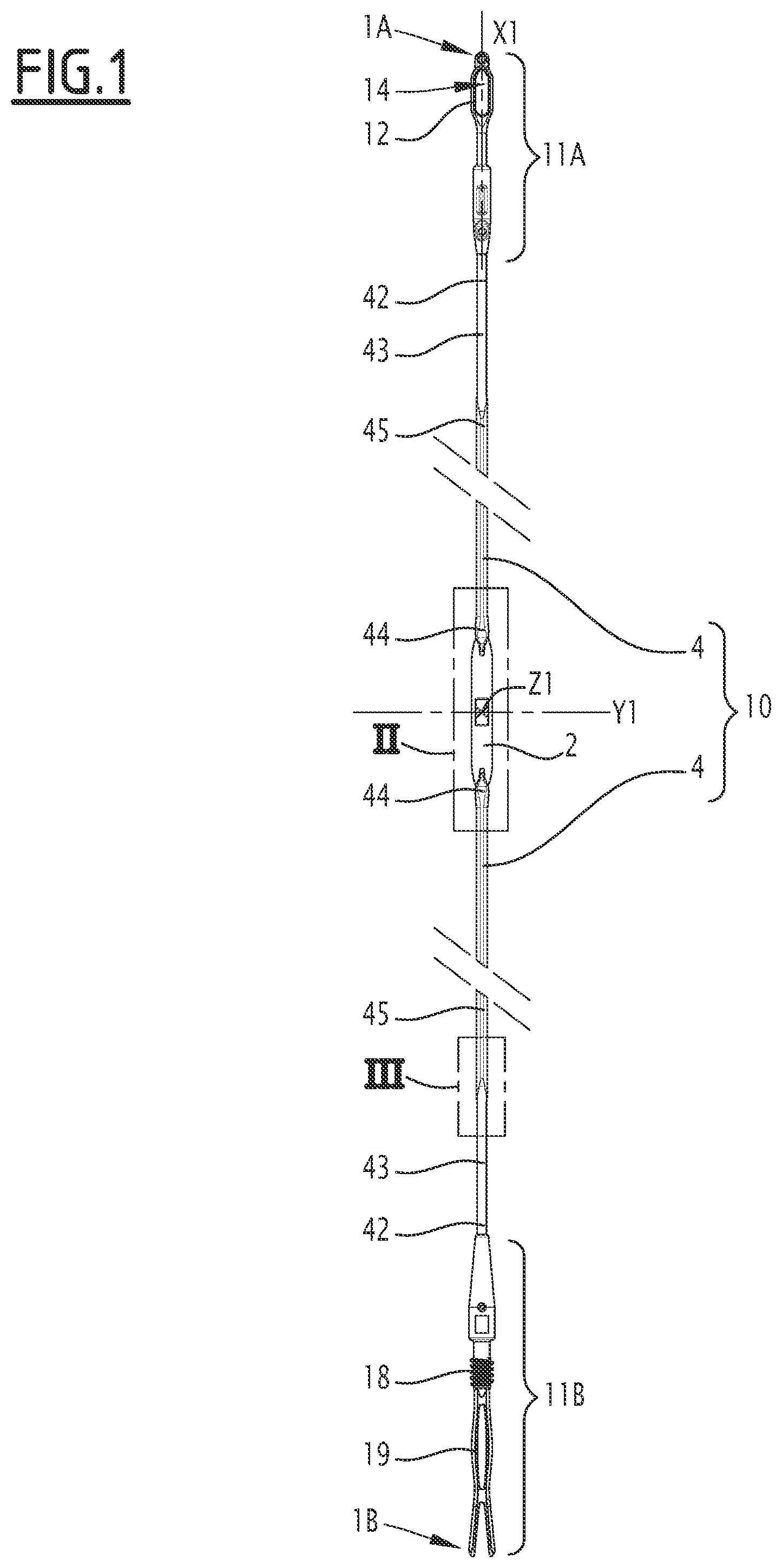
is an elevation view of a warp thread guiding heddle for a Jacquard weaving loom, in accordance with a first embodiment of the invention;
is a larger scale view of detail Il in ;
shows, on insert A), a larger scale view of detail Ill in , on insert B), a side view in the direction of arrow B on insert A) and, on insert C), a section according to line C-C of insert A);
shows, on two inserts A) and B), a front view and a longitudinal section according to plane B-B of a link belonging to the heddle of to 3 ;
shows, on two inserts A) and B), a side view of a junction zone between a rod and the link of the heddle of to 3 , as well as a partial longitudinal section according to plane V-V in ;
shows the same junction zone in elevation in the direction of arrow VI in , as well as several sections taken at section lines A-A, B-B, C-C and D-D respectively;
shows, on two inserts A) and B), two perspective views of the junction zone, seen according to two different angles;
is a view similar to insert A) of for a heddle in accordance with a second embodiment;
shows, on three inserts A), B) and C), a side view, a longitudinal section and a front view, in the direction of arrow C on insert A), of the junction zone of the heddle of the second embodiment;
is a front view similar to for a heddle in accordance with a third embodiment, as well as several sections taken respectively at section lines A-A, B-B, C-C and D-D; and
is a schematic representation of a Jacquard-type weaving loom in accordance with the invention, incorporating at least one of the heddles shown in to 10 , as well as a harness in accordance with the invention.
DESCRIPTION
The Jacquard-type weaving loom M shown in is equipped with a Jacquard mechanism 102 which controls a number of hooks 104 . A lower extremity of each hook 104 is associated with a yoke 106 . A lower extremity 106 a of each yoke 106 is connected to an upper extremity 1 a of a heddle 1 equipped with a link 2 guide for a warp thread 108 . Each heddle 1 is connected by its lower extremity 1 b to a spring 110 fixed to a hanging beam 112 , the beam 112 being securely fixed to a frame, not shown, on the weaving loom M. The various yokes 106 are distributed, across the depth and width of the weaving loom, passing through holes arranged in a stuffing board 114 . The elements 1 , 106 , 110 and 114 form a harness H belonging to the weaving loom M and controlled by the Jacquard mechanism 102 .
The heddles shown in to 10 are intended to be integrated into the harness H.
to 7 show a first embodiment of a heddle 1 guide for a warp thread of the harness H on the weaving loom M.
The heddle 1 guide extends according to a longitudinal axis X 1 and comprises a heddle body 10 and a link 2 . The heddle body 10 includes two separate rods 4 arranged on either side of the link 2 , along the longitudinal axis X 1 .
The rods 4 are made of a polymer, such as Nylatron (registered trademark) or natural polyamide PA6, preferably unfilled. They are overmolded onto the link 2 , in other words, obtained by an overmolding operation around the link 2 .
Overmolding means that link 2 is at least partially placed in an injection mold formed of at least two portions of the mold which together define a recess around the link 2 . This recess is filled by injecting polymer material intended to form a rod 4 . In practice, the two rods 4 of the heddle 1 are advantageously overmolded at the same time on the link 2 in a mold forming two recesses. Each of the rods constituted at the end of the overmolding operation is, preferably, one-piece. As explained below, each rod 4 is anchored in the link 2 by a part of the rod, called the heel, which is engaged in a housing defined by the link.
Y 1 and Z 1 are two axes of the heddle 1 which are perpendicular to the longitudinal axis X 1 . The axis Y 1 extends according to the width of link 2 , while the axis Z 1 extends according to the thickness of the link 2 . The Y 1 axis constitutes a transverse axis for the heddle 1 , while the axis Z 1 constitutes a thickness axis for the heddle 1 . The center of the reference frame formed by axes X 1 , Y 1 and Z 1 is located at the geometric center C 22 of an eyelet 22 of the link 2 .
At each extremity, the heddle body 10 presents hooking means 11 A or 11 B, respectively provided to cooperate with a yoke 106 or a spring 110 . More precisely, one of the rods 4 , shown in the upper part of , carries the hooking means 11 A on a first extremity 42 , while the other rod 4 , shown in the lower part of , carries on a first extremity 42 the hooking means 11 B. The hooking means 11 A comprises an end piece 12 which forms an opening 14 for the passage and clamping of a yoke 106 by a tube, not shown, mounted around the upper rod 4 . The hooking means 11 B comprises an external thread 18 which is intended to be screwed into the spring 110 and a sliding damper 19 .
The hooking means 11 A and 11 B are respectively arranged at the upper 1 A and lower 1 B extremities of the heddle 1 and are, preferably, manufactured by overmolding on the link 2 , at the same time as the rest of the rods 4 .
The examples of the hooking means 11 A and 11 B are not limiting. For example, the hooking means 11 A may be in accordance with the teachings of CN-U-210596433.
The rods 4 are identical to each other, except for the hooking means 11 A and 11 B.
Opposite its first longitudinal extremity 42 , each rod 4 comprises a second longitudinal extremity 44 by which it is connected to the link 2 , by overmolding. Note that 44 A is the free edge of the second longitudinal extremity 44 of a rod 4 , which is opposite its first longitudinal extremity.
Each rod 4 comprises two portions 43 and 45 , which are integral with each other, which define the longitudinal extremities 42 and 44 respectively, and which present a circular and non-circular cross-section respectively. Thus, the portion 43 has a circular cross-section, while the portion 45 has a non-circular cross-section. Along the longitudinal axis X 1 , the portion 43 is arranged between the portion 45 and the hooking means 11 A or 11 B, and the portion 45 is arranged between the portion 43 and the link 2 .
As shown in , the circular cross-section of the portion 43 is centered on an axis X 43 parallel to the longitudinal axis X 1 and offset from the longitudinal axis X 1 by a non-zero distance d 43 measured parallel to the thickness axis Z 1 . A transverse axis is noted Y 43 parallel to the transverse axis Y 1 and offset relative to it by the distance d 43 , in the same direction as the axis X 43 relative to the axis X 1 . The plane containing the axes X 43 and Y 43 is a plane of symmetry of the portion 43 of the rod 4 .
The transverse section, perpendicular to the longitudinal axis X 1 , of the portion 45 is constant, except at the second longitudinal extremity 44 and its junction with the portion 43 . In other words, the second longitudinal end 44 of the rod 4 is a part of the portion 45 , the transverse section of which varies along the longitudinal axis X 1 .
The link 2 is formed from a sheet of metal of single thickness, preferably stainless steel. It is advantageously obtained by cutting a sheet of metal.
The link extends according to a longitudinal axis X 2 . A transverse axis, noted Y 2 , according to which the width of link 2 extends, and a thickness axis, noted Z 2 , according to which the thickness of this link extends. In the overmolded configuration of the rods 4 on the link 2 , the axes X 2 , Y 2 and Z 2 are respectively coincident with the axes X 1 , Y 1 and Z 1 .
The link 2 includes a central portion 20 which presents polished rounded lateral edges 21 and which defines the eyelet 22 for the passage of a warp thread 108 , with rounded edges. This eyelet 22 passes right through the link 2 according to the thickness axis Z 2 . The axes X 2 , Y 2 and Z 2 intersect at the geometric center C 22 of the eyelet 22 at mid thickness of the link. The eyelet 22 is rectangular in shape in the main plane of the link 2 , which is the median plane of the central portion 20 and contains the axes X 2 and Y 2 . The geometric center C 22 is a point of symmetry of the link 2 , which facilitates its placement in the mold for the overmolding operation of the rods 4 , without any prerequisite as to its orientation.
The link 2 also comprises two longitudinal lugs 24 that extend its central part 20 , according to the longitudinal axis X 2 , at its two opposite longitudinal extremities. The lugs 24 are longitudinal extremity lugs and each presents a reduced width relative to the width of the central portion 20 . Between the central portion 20 and the lugs 24 , the width of the link measured according to the transverse axis Y 2 decreases progressively toward the lugs 24 and the lateral edges 21 of the central portion 20 are extended by curved edges 25 , which between them delimit a transition zone 26 between the central portion 20 and a longitudinal lug 24 .
In the example shown in the figures, the transition zone 26 is a zone where the width of the link 2 decreases away from the eyelet 22 along the longitudinal axis X 1 .
The lateral edges of the longitudinal lugs 24 are noted 27 .
A first transverse face and a second transverse face of link 2 , are noted 28 and 29 respectively. These transverse faces being parallel to the axes X 2 and Y 2 . The first transverse face 28 is visible in , 2 , 4 , 5 and on insert B) of , while the second transverse face 29 is visible in , 5 , 6 and on insert A) of . The transverse faces 28 and 29 are opposite each other and offset along the thickness axis Z 2 by the thickness e 2 of the link 2 , which is constant. The transverse faces 28 and 29 extend over the entire surface of the link 2 , from the eyelet 22 to the longitudinal lugs 24 .
In each of the transition zones 26 is arranged an elongated housing 32 , which constitutes an orifice and passes right through the link 2 , between its transverse faces 28 and 29 , in other words, parallel to the thickness axis Z 2 . The largest dimension of an elongated housing 32 extends according to the longitudinal axis X 2 .
A peripheral surface of link 2 is noted 31 , in other words, the outer edge of this link excluding the eyelet 22 and outside the housings 32 . The peripheral surface 31 includes the longitudinal edges 21 , the curved edges 25 and the lateral edges 27 .
Each elongated housing 32 comprises a first proximal lobe 322 , on the side of the eyelet 22 , and a second distal lobe 324 , on the side of a longitudinal lug 24 . The lobes 322 and 324 communicate with each other according to the longitudinal axis X 2 . Each housing 32 is thus keyhole-shaped overall.
The elongated housings 32 are symmetrical to each other relative to a plane containing the axes Y 2 and Z 2 , which passes through the geometric center C 22 . Furthermore, each elongated housing 32 is symmetrical relative to a plane containing the axes X 2 and Z 2 , which passes through the geometric center C 22 .
Each housing 32 is delimited by a closed contour which comprises, according to the longitudinal axis X 2 , a proximal portion 323 , which defines the bottom of the proximal lobe 322 on the side of the eyelet 22 , and a distal portion 325 , which defines the bottom of the distal lobe 324 on the side of the nearest longitudinal lug 24 .
The second longitudinal extremity 44 of each overmolded rod 4 partially covers the two transverse faces 28 and 29 of the link 2 , at the transition zones 26 , and passes through the link at the level of the housings 32 , right through between the transverse faces 28 and 29 . As it passes through the housing 32 , the second longitudinal extremity 44 of each rod 4 forms an anchoring heel 442 which cooperates with the contour of this housing, in such a way that this cooperation opposes relative displacement between the rod 4 and the link, in both the longitudinal and transverse directions, in other words, parallel to the axes X 1 and Y 1 . In particular, the cooperation of the heel 442 with the contour of the housing 32 opposes a separation of the rod 4 and the link 2 parallel to the longitudinal axis X 1 .
The trace of the anchoring heel 442 in the cross-sectional plane of insert B) in is shaded. Each anchoring heel 442 is formed during overmolding on the link 2 of the rod 4 to which it belongs.
Each anchoring heel 442 passes right through the housing 32 in which it is formed, between the first and second transverse faces 28 and 29 . The anchoring heel 442 passes seamlessly through the housing 32 .
Each anchoring heel 442 completely fills the elongated housing 32 in which it is formed. In particular, the heel 442 rests against the proximal and distal portions 323 and 325 of the closed contour of this housing, which blocks any relative displacement of the second longitudinal extremity 44 relative to the link 2 according to the directions parallel to the longitudinal axis X 1 . This anchoring of the heel 442 in the housing 32 also blocks any displacement between the rod 4 and the link 2 according to a transverse direction, parallel to the transverse axis Y 1 .
In this embodiment, the part of the anchoring heel 442 resting against the proximal portion 323 of the closed contour of the housing 32 forms the free edge 44 A of the second extremity 44 of the rod 4 .
The second extremity 44 of a rod 4 presents a first covering surface S 448 which partially covers the first transverse face 28 of the link 2 , on a first side of a transition zone 26 , and a second covering surface S 449 which partially covers the second transverse face 29 of the link 2 , on a second side of the same transition zone 26 , opposite the first side according to the axis Z 1 . The trace of the covering surface S 448 is shaded in . Each of the covering surfaces S 448 and S 449 is delimited by the anchoring heel 442 . In other words, the covering surfaces S 448 , S 449 extend as far as the anchoring heel 442 . The covering surfaces S 448 and S 449 are coplanar with the first transverse face 28 , the second transverse face 29 respectively, and therefore extend parallel to the plane formed by the axes X 1 , Y 1 and perpendicular to the thickness axis Z 1 . A portion of the link 2 is therefore covered by, and embedded between, the two covering surfaces S 448 and S 449 of the second longitudinal extremity 44 of each rod 4 . This prevents any relative displacement between the rod 4 and the link 2 in the two directions perpendicular to transverse faces 28 and 29 , in other words, in the two directions parallel to the thickness axis Z 1 .
Thus, each second longitudinal extremity 44 of a rod 4 is integral with the link 2 , with no possibility of movement in any direction.
The second longitudinal extremity 44 is in one piece. It defines the covering surfaces S 448 , S 449 and comprises the anchoring heel 442 . Thus, the covering surfaces S 448 , S 449 and the anchoring heel 442 are obtained by filling the same recess in the same overmolding operation.
The portion of the anchoring heel 442 closest to the proximal portion 323 of the housing 32 is delimited according to the thickness axis Z 1 by two surfaces S 442 and S′ 442 , respectively on the side of the first transverse face 28 and on the side of the second transverse face 29 . The surfaces S 442 and S′ 442 are flat and parallel to the adjacent transverse faces 28 and 29 respectively.
Advantageously, the surface S 442 is flush with the first adjacent transverse face 28 , while the surface S′ 442 is flush with the second adjacent transverse face 29 . Thus, it is possible to limit snagging of adjacent warp threads 108 as they move into contact with the link 2 .
On the side of each transverse face 28 or 29 of the link 2 , the second longitudinal extremity 44 of a rod 4 has a curved external shape, with a thickness e 4 , measured according to the thickness axis Z 1 , which decreases as it approaches the heel 442 , until it takes on a value equal to the thickness e 2 of the link 2 , at the level of the portion of the heel 442 defined between the surfaces S 442 and S′ 442 .
The width of the second longitudinal extremity 44 is noted 44 measured parallel to the transverse axis Y 1 on the side of the transverse face 28 . The width of the second longitudinal extremity 44 is noted ′ 44 , measured parallel to the transverse axis Y 1 on the side of the transverse face 29 . On each side of the link 2 , the width 44 or ′ 44 decreases as it approaches the free edge of the heel 442 , until it takes on a value equal to the width of the free edge of the heel 442 or the proximal portion 323 of the elongated housing 32 . Overall, on either side of the link 2 , and as visible in , the second longitudinal extremity 44 of a rod 4 has a shape comparable to the head of a dolphin whose beak is constituted by the portion of the heel 422 delimited by the surface S 442 or S′ 442 .
As can be seen from sections B-B and C-C of , the longitudinal lugs 24 are completely embedded in the second longitudinal extremities 44 of the rods 4 . In other words, the lateral edges 27 , the portions of the transverse faces 28 , 29 and the free edge at each lug 24 are in contact with the associated second longitudinal extremity 44 . In other words, each second longitudinal extremity 44 completely surrounds a longitudinal lug 24 .
The outer surface of rod 4 is noted S 4 .
This outer surface S 4 has a non-circular cross-section on the portion 45 and terminates, on the eyelet 22 side, with surfaces S 442 and S′ 442 .
It is considered that for each rod 4 , a parting plane is defined by the mold in which the rod 4 is overmolded onto the link 2 . This parting plane corresponds to a plane of closure of the two portions of the mold forming the recess for the rod 4 around the link 2 . This parting line is parallel to, and in line with, the first transverse face 28 of the link 2 . A plane forming the trace of the parting line on the heddle 1 is noted as π. The plane π includes the first transverse face 28 and the covering surface S 448 .
As can be seen from the comparison of inserts A and B in , the external shape of the extremity 44 is different when viewed from the side of the first transverse face 28 or from the side of the second transverse face 29 . In other words, the geometry of the outer surface S 4 is different according to when viewed from one side or the other of the rod 4 , relative to the plane π on the rod 4 . This geometry is imposed by the recess of the mold used during the overmolding operation.
More precisely, in a part of the second longitudinal extremity 44 along the longitudinal axis X 1 , the width ′ 44 is strictly less than the width 44 .
A cavity C 44 is formed by the rod 4 and the link 2 on either side of the second longitudinal extremity 44 , relative to a plane containing the axes X 1 and Z 1 . This cavity extends, according to the transverse axis Y 1 , beyond the part of the link 2 that is covered by the second extremity 44 of the rod 4 .
The two cavities C 44 arranged on the second longitudinal extremity 44 are symmetrical to each other relative to the plane containing the axes X 1 and Z 1 . The following description applies to either of these cavities. The second longitudinal extremity referred to in the following is the second longitudinal extremity 44 of one of the rods 4 .
The cavity C 44 is defined by a first surface S 1 of the link 2 , by a second lateral surface S 2 of the rod 4 and a third bottom surface S 3 of the rod 4 .
The bottom surface S 3 extends, in the direction of the first longitudinal extremity 42 , in particular according to the longitudinal axis X 1 , the first covering surface S 448 formed by the second longitudinal extremity 44 . In other words, the junction between the bottom surface S 3 and the first covering surface S 448 is a line contained in the plane formed by the first covering surface S 448 . In the first embodiment and in an advantageous way, the bottom surface S 3 is in the plane π. The surfaces S 3 and S 448 are therefore coplanar. The third bottom surface S 3 is in the extension, according to the longitudinal axis X 1 and beyond the peripheral surface 31 , of the first transverse face 28 of the link 2 . In the first embodiment and in an advantageous way, the surface S 3 and the first transverse face 28 are also coplanar.
Alternatively, the surfaces S 3 and S 448 , of which, the surface S 3 and the first transverse face 28 , are substantially coplanar without being strictly coplanar, forming an angle of less than 10° between them.
The first surface S 1 is constituted by a portion of a curved edge 25 of the link 2 , which is arranged on the side of the third bottom surface S 3 according to a direction parallel to the longitudinal axis X 1 . In other words, the first surface S 1 is constituted by a portion of the peripheral surface 31 , at one of the transition zones 26 , where the width of the link decreases when moving away from the eyelet 22 according to the longitudinal axis X 1 .
The second lateral surface S 2 is formed by a portion of the outer surface S 4 which extends in the direction of the first longitudinal extremity 42 from a line L 44 which forms the intersection between the outer surface S 4 and the peripheral surface 31 of the link 2 . Within the cavity C 44 , the intersection line L 44 delimits the first surface S 1 . The intersection line L 44 defines the junction between the first surface S 1 and the second surface S 2 . The second surface S 2 is said to be lateral in the sense that the second surface S 2 is not parallel to the transverse axis Y 1 . The second lateral surface S 2 therefore extends generally transversely toward the axis Y 1 . The second lateral surface S 2 delimits the cavity C 44 laterally, in other words, according to the transverse axis Y 1 , toward the inside, in other words, in the direction of the longitudinal axis X 1 . The intersection line L 44 is arranged at the same longitudinal level as the second covering surface S 449 . The intersection line L 44 extends from the first transverse face 28 to the second transverse face 29 . In particular, the intersection line L 44 extends from the first covering surface S 448 to the second covering surface S 449 . The intersection line L 44 extends, within the cavity C 44 , from the third bottom surface S 3 .
In insert A) of , the first, second and third surfaces S 1 , S 2 and S 3 are identified by zones with dots, with different densities, in order to facilitate their location. Similarly, an axis line has been added to the extension of the intersection line L 44 , to make it easier to locate.
The third bottom surface S 3 extends laterally, in other words, according to a direction parallel to the transverse axis Y 1 , and away from the longitudinal axis X 1 , in other words, toward the outside, relative to the part of the link 2 located in the same zone as this bottom surface S 3 along the longitudinal axis X 1 . In other words, the bottom surface S 3 extends at a distance from the plane comprising the axes X 1 and Z 1 which is non-zero and which is greater than the distance between this plane and the portions of the peripheral surface 31 embedded in the material of the second longitudinal extremity 44 , in particular the lateral edges 27 of the longitudinal lugs 24 .
Thus, each cavity C 44 is offset from the link 2 parallel to the transverse axis Y 1 .
In addition, each cavity C 44 is advantageously offset from the link 2 parallel to the longitudinal axis X 1 . In other words, the third bottom surface S 3 extends according to a direction parallel to the longitudinal axis X 1 , in the direction of the first longitudinal extremity 42 , relative to the part of the link 2 located in the same zone as this bottom surface S 3 along the longitudinal axis Y 1 .
In this case, the cavity C 44 is offset from the link 2 parallel to all directions of the transverse faces 28 and 29 of this link, in other words, in all directions parallel to the covering surfaces S 448 and S 449 . In other words, the cavity C 44 is arranged laterally on the outside of the link and longitudinally beyond, in the direction of the first longitudinal extremity 42 , the parts of the link not covered by the second extremity 44 .
A first re-entrant edge A 1 is defined at the junction between the first surface S 1 and the third bottom surface S 3 . This edge A 1 also corresponds to the junction line between the first covering surface S 448 and the third bottom surface S 3 . This edge A 1 extends to the intersection line A 44 .
A second re-entrant edge A 2 defines the junction between the second lateral surface S 2 and the third bottom surface S 3 . The second lateral surface S 2 and the third bottom surface S 3 meet at the edge A 2 . The edge A 2 extends generally according to the longitudinal axis X 1 .
An outer edge A 3 delimits the third bottom surface S 3 laterally toward the outside. The edge A 3 is a junction edge between one extremity of the edge A 1 opposite the intersection line L 44 and one extremity of the junction edge A 2 opposite this same intersection line. This edge A 3 is protruding and connects the third bottom surface S 3 to a portion S 44 of the outer surface S 4 which defines the outer shape of the second longitudinal extremity 44 on the side of the transverse face 28 of the link 2 , in other words, on the side visible on insert B) in . In other words, the bottom surface S 3 opens onto the portion S 44 of the outer surface S 4 . The portion of the surface S 44 extends the surface S 442 away from the eyelet 22 .
In other words, the cavity C 44 is defined by:
•
• a re-entrant dihedron between the surfaces S 1 and S 2 , with the intersection line L 44 as the common line, • a re-entrant dihedron between the surfaces S 1 and S 3 , with the edge A 1 as the common line, and • a re-entrant dihedron between the surfaces S 2 and S 3 , with the edge A 2 as the common line.
Each of the cavities C 44 constitutes a reinforcement in which the presence of burrs is not objectionable, as there is no risk of these burrs coming into contact with warp threads adjacent to the heddle 1 , when the latter is integrated into the harness H and when the weaving loom M is in operation.
In particular, on each side of the plane X 1 , Z 1 , each cavity C 44 constitutes a recess for the intersection line L 44 which is the sole junction of the outer surface S 4 of the rod 4 with the peripheral surface 31 of the link 2 on this side of the plane X 1 , Y 1 .
A plane parallel to axes X 1 and Y 1 and which includes the transverse face 29 and the covering surface S 449 is noted π′.
According to the thickness axis Z 1 , the second lateral surface S 2 is between the planes π and π′.
A portion of the outer surface S 4 located on the side of the π′ plane opposite the lateral surface S 2 is noted S′ 44 . The portion of the surface S′ 44 is visible in insert A) of and opposite the portion of the surface S 44 . It extends the surface S′ 442 away from the eyelet 22 .
The width 44 is the width of surface S 44 and width ′ 44 is the width of the surface S′ 44 , measured parallel to transverse axis Y 1 . The widths 44 and ′ 44 decrease from the bottom surface S 3 toward the free edge of the heel 442 .
The third bottom surface S 3 extends according to a transverse direction parallel to the transverse axis Y 1 , toward the outside, relative to the second side surface S 2 .
The thickness of the rod 4 measured parallel to the thickness axis Z 1 is noted e 4 max , in the part of the portion 45 of the rod 4 with constant cross-section. The embedding thickness of the link 2 is noted e 44 , in the second longitudinal extremity 44 , on the side of the first transverse face 28 . The thickness e 44 is the maximum distance, measured parallel to the thickness axis Z 1 at the longitudinal level of the cavities C 44 , in other words, longitudinally between the intersection of the edges A 3 and A 2 and the intersection of the edges A 3 and A 1 , between the plane of the first covering surface S 448 and the surface S 44 . The embedding thickness of the link 2 in the second longitudinal extremity 44 , on the side of the second transverse face 29 , is noted e′ 44 . The thickness e′ 44 is the maximum distance, measured parallel to the thickness axis Z 1 at the longitudinal level of the cavities C 44 , between the plane of the second covering surface S 449 and the surface S′ 44 . The following relationship applies:
e 4 max = e 2 + e 4 4 + e ′ 44. ( equation 1 )
Each of the thicknesses e 44 and e′ 44 is greater than or equal to the thickness e 2 . The following relationships apply: e 44≥ e 2 (equation 2) e′ 44≥ e 2 (equation 3)
At the longitudinal level of the cavity C 44 , the outer surface S 4 of the rod 4 presents a maximum height, measured parallel to the thickness axis Z 1 relative to the plane of the first covering surface S 448 , which is equal to e′ 44 +e 2 and is therefore greater than or equal to twice the thickness e 2 .
A re-entrant edge which extends to the junction between the surface S 44 and the transverse face 28 is noted A 48 . This edge is contained in the plane π and borders the covering surface S 448 on the outside. A re-entrant edge which extends to the junction between the surface S′ 44 and the transverse face 29 is noted A 49 . This edge is contained in the plane π′ and borders the covering surface S 449 on the outside. Each intersection line L 44 of each of the two cavities C 44 present on the rod 4 extends to the edge A 49 .
When the heddle 1 is integrated into the harness H, the adjacent warp threads can be considered as straight because they are taut and extend generally according to a direction transverse to the axis X 1 . In this case, if one of these threads comes to rub against the second longitudinal extremity 44 , it comes into contact with one or other of the surfaces S 44 or S′ 44 but cannot penetrate inside one of the cavities C 44 , given their geometry. Under these conditions, there is no risk of such a thread being snagged, damaged or severed by burrs that are found inside this cavity.
However, it is inside each cavity C 44 that burrs are most likely to form, along the intersection line L 44 and/or along one of the edges A 1 and A 2 .
Different positions of a warp thread 108 resting against the second longitudinal extremity 44 of the heddle 1 are represented by thick mixed lines in section C-C of . The geometry of the second longitudinal extremity 44 maintains the warp thread 108 outside the two cavities C 44 , at a distance from the edges A 1 , A 2 and the line L 44 .
The edge A 3 is flat and is contained in the plane π, parallel to the axes X 1 and Y 1 . Its concavity is turned toward the plane comprising the axes X 1 and Z 1 and therefore toward the second lateral surface S 2 . In other words, the edge A 3 bulges outward between the edges A 1 and A 2 , in a plane parallel to the axes X 1 and Y 1 .
On the other hand, no surface of the heddle 1 faces the cavity C 44 away from the third bottom surface S 3 according to the thickness axis Z 1 perpendicular to this third bottom surface, and therefore perpendicular to the covering surface S 448 . In other words, the cavity C 44 , and in particular, the third bottom surface S 3 , the first surface S 1 and the second lateral surface S 2 , face away from each other in a direction D 1 parallel to the thickness axis Z 1 and away from the portion of the second longitudinal extremity 44 of the rod 4 that forms this surface S 3 . This allows the cavity C 44 to be created by means of a mold with a parting line π and no slide, which is advantageous in terms of cost, reliability of the overmolding operation and reduced burrs.
The first surface S 1 and the joining edge A 3 each have a projection, in a plane parallel to the longitudinal and transverse axes X 1 , Y 1 , which is an arc of a circle. The radius of curvature of the projection of surface S 1 in a plane parallel to the axes X 1 and Y 1 is noted R 1 , in other words, of the portion of the curved edge that delimits the cavity C 44 . The radius of curvature of the projection of the edge A 3 in the same plane parallel to the axes X 1 and Y 1 is noted R 3 . The radii of curvature R 1 and R 3 are shown in . The radius of curvature R 3 is greater than or equal to the radius of curvature R 1 , preferably greater than or equal to 1.5 times this radius R 1 .
This relatively large radius of curvature R 3 of the edge A 3 , compared with that of the curved edge 25 , gives the bottom surface S 3 a tapered geometry, advantageous for preventing a warp thread 108 from engaging in the cavity C 44 defined by this joining edge A 3 .
Each housing 32 is arranged, along the longitudinal axis X 1 , predominantly on the side of the eyelet 22 relative to the cavities C 44 of the adjacent second longitudinal extremity 44 . In particular, the proximal portion 323 of a housing 32 is arranged, along the longitudinal axis X 1 , between the nearest cavities C 44 and the eyelet 22 . In an alternative not represented, the distal portion 325 of a housing 32 is arranged, along the longitudinal axis X 1 , between the nearest cavities C 44 and the eyelet 22 .
For each rod 4 , each covering surface S 448 , S 449 is predominantly, preferably exclusively, arranged at the longitudinal level of each cavity C 44 as well as on the longitudinal side of the eyelet 22 relative to each cavity C 44 .
Advantageously, at the level of each second longitudinal extremity 44 , the two cavities C 44 have first surfaces S 1 , two second lateral surfaces S 2 and third bottom surfaces S 3 which are not facing each other according to the same direction D 1 , perpendicular to the transverse faces 28 and 29 of the link 2 . Furthermore, the two third bottom surfaces S 3 of the two cavities C 44 of the same rod 4 are coplanar.
In practice, taking into account that two cavities C 44 are provided at each of the second longitudinal extremities 44 of the two rods 4 , the heddle 1 has four cavities C 44 . The four third bottom surfaces S 3 of these four cavities C 44 are advantageously coplanar, which allows, for the overmolding mold of the rods 4 , to use a single parting line, which simplifies the manufacture of this mold and also reduces burrs at this parting line.
The plane π is offset from the median plane of the eyelet 22 , which contains the axes X 1 and Y 1 , by half the thickness e 2 of this eyelet. This allows the third bottom surface S 3 to be in the extension of with the covering surface S 448 and the transverse face 28 .
In addition, the distance d 43 is equal to half the thickness e 2 . Thus, the axis X 43 is contained in the plane π and the plane of symmetry X 43 , Y 43 of portion 43 of the rod 4 is coplanar with the third bottom surface S 3 of each cavity C 44 . This means that the portion 43 of each rod 4 is symmetrical relative to the parting line of the mold.
The second longitudinal extremities 44 of the two rods 4 are symmetrical to each other relative to a plane parallel to the axes Y 1 and Z 1 and passing through the center of the eyelet 22 . As a result, the plane π is the same for both rods. Once again, this simplifies mold manufacturing and limits burrs.
The distance measured between the junction edge A 3 and the intersection line L 44 is noted d 3 . Advantageously, the minimum value of the distance d 3 is greater than or equal to half the thickness e 2 of the link 2 . When the junction edge A 3 is contained in the plane π, then d 3 is the distance measured in the plane π between the junction edge A 3 and the trace of intersection line L 44 in this plane. In practice, the minimum value of the distance d 3 can be chosen between 0.1 and 0.15 millimeters, which gives good results for sufficiently spacing the warp threads 108 from the burrs present inside the cavity C 44 , without significantly widening or weighing down the rod 4 .
In view of the above, it is understood that the effect of the cavities C 44 is that the intersections between the rods 4 and the link 2 that are most critical in terms of burr creation, namely those intersections that are essentially perpendicular to the longitudinal axis X 1 , in particular at the intersection line L 44 and the edges A 1 , are set back in each cavity C 44 , therefore, at a distance from an adjacent warp thread 108 that presses against one or other of the surfaces S 44 or S′ 44 , as represented in section C-C of .
This applies in particular at the intersection line L 44 , which is perpendicular, to within 10°, to the third bottom surface S 3 .
In an alternative, not represented, the intersection line L 44 is curved.
Burrs can also be created during the overmolding operation, on essentially rectilinear portions of the rod 4 , parallel to the longitudinal axis X 1 and located outside the second extremity 44 , therefore outside the cavities C 44 . These burrs are less aggressive than those that may be created in zones that are not parallel to the longitudinal axis X 1 .
Other burrs can also be created along the re-entrant edges A 48 and A 49 , but they do not risk snagging the warp threads 108 as these are straight and come to rest against the peripheral surface 31 of the link 2 and against one of surfaces S 44 and S′ 44 , without touching the edges A 48 and A 49 .
In the second and third embodiments shown in and following, elements similar to those in the first embodiment carry identical references. If a reference is shown on one of and following without being mentioned in the rest of the description or mentioned in the description without being shown on these figures, it relates to the same element as the one carrying the same reference in the first embodiment. In the following, we will mainly describe what distinguishes the Jacquard heddle guides of these second and third embodiments from the first embodiment.
In the second embodiment, the housings 32 of the link 2 are notches which open out at the longitudinal extremities of this link. In other words, no lugs comparable to the longitudinal lugs 24 of the first embodiment are provided, and the contour of the housings 32 is open. This contour does not comprise a portion comparable to the distal portion 325 of the first embodiment. The peripheral surface 31 is defined outside the contour of the housings 32 and outside the eyelet 22 and includes the longitudinal edges 21 and the curved edges 25 .
Another difference relative to the first embodiment is that the link 2 presents a thickness e 2 , measured parallel to the thickness axis Z 2 , which is not constant. This thickness is greater in the central portion 20 , which defines the eyelet 22 , than in the transition zone 26 , as can be seen in . The transverse faces 28 and 29 are parallel to the axes X 1 and Y 1 , except for the portion of the transverse face 28 where the thickness e 2 varies.
The trace of the covering surface S 448 is shaded in .
Two cavities C 44 are respectively formed on either side of a plane containing the axes X 1 and Z 1 of the second longitudinal extremity 44 of the rod 4 , each being defined by a first surface S 1 , a second side surface S 2 and a third bottom surface S 3 . The cavities C 44 have substantially the same geometry as in the first embodiment.
The variable feature of the thickness e 2 allows the plane π in which is located the third bottom surface S 3 of the cavities C 44 to be coplanar with the median plane of the link 2 defined by the axes X 2 and Y 2 at the center C 22 of its eyelet 22 . In other words, the geometry of the link 2 , which presents a reduction in thickness visible in , allows the parting line of the mold, that is, the plane π defined as in the first embodiment, and the third bottom surface S 3 of the cavity 44 with the median plane of the link 2 to be aligned.
In this embodiment, the anchoring heel 442 does not fill the entire housing 32 in which it is overmolded. In particular, no part of the heel 442 presents surfaces comparable to the surfaces S 442 and S′ 442 of the first embodiment. A free edge 442 A of the anchoring heel 442 extends, along the longitudinal axis X 1 , at a non-zero distance d 442 from the proximal portion 323 of the unclosed contour of the housing 32 in which this anchoring heel 442 is overmolded. The anchoring heel 442 passes right through the housing 32 , between the transverse faces 28 and 29 of the link 2 . In this second embodiment, the free edge 442 A of the anchoring heel forms the free edge 44 A of the second extremity 44 of the rod 4 .
In the third embodiment, the two cavities C 44 defined on either side of a plane containing the axes X 1 and Z 1 of a second longitudinal extremity 44 of a rod 4 of the heddle 1 have their respective third bottom surfaces S 3 which are not coplanar but defined respectively in the extension of two covering surfaces S 448 and S 449 formed by the second longitudinal extremity 44 and which partially cover, at the transition zones 26 , respectively the transverse faces 28 and 29 of the link 2 . The trace of the covering surface S 448 is shaded in gray in . This covering surface S 448 is not symmetrical relative to the plane containing the axes X 1 and Z 1 .
The third bottom surfaces S 3 of the two cavities C 44 arranged on either side of a second longitudinal extremity 44 are defined by two planes π and π′ parallel and offset, parallel to the thickness axis Z 1 , by a distance dπ equal to the thickness e 2 of the link 2 at the transition zones 26 . In this embodiment, there is therefore no single parting line for the mold in which each rod 4 is overmolded onto the link 2 . However, on the rod 4 , either side of the plane X 1 , Y 1 , the parting line extends exclusively in the plane π, respectively in the plane π′, which limits the formation of overmolding burrs that can create snags for neighboring warp threads.
The two cavities C 44 are not limited according to the respective directions D 1 and D′ 1 which are perpendicular to the covering surfaces S 448 and S 449 , parallel to the axis Z 1 , and each oriented away from the portion of the second longitudinal extremity 44 of the rod 4 which defines the respective bottom surface S 3 . These two directions D 1 and D′ 1 are opposite to each other, that is, directed upward for the direction D 1 taken into account for the cavity C 44 shown on the right of the section C-C of and downward for the direction D′ 1 taken into account for the cavity C 44 shown on the left of this section.
In this third embodiment, the link 2 is identical to that of the first embodiment. The heel 442 extends as far as the proximal portion 323 of the contour of the housing 32 , with the surfaces S 442 and S′ 442 defined as in the first embodiment which are respectively parallel to the transverse faces 28 and 29 of the link 2 , which are not flush with these transverse faces 28 and 29 but located set back therefrom, toward the inside of the housing 32 , so as not to snag the adjacent warp threads 108 when these displace into contact with the link 2 .
Using the same notation conventions as for the first embodiment, we have the following relationships:
e 4 max = e 2 + e 4 4 + e ′ 44 ( equation 1 ) e 44 ≥ e 2 ( equation 2 ) e ′ 44 ≥ e 2 ( equation 3 )
In this third embodiment, as in the first embodiment, the part of the anchoring heel 442 which rests against the proximal portion 323 of the closed contour of the housing 32 forms the free edge 44 A of the second extremity 44 of the rod 4 .
In an alternative, not represented, of the invention, the two cavities C 44 of the upper rod 4 , which carries the hooking means 11 A, are non-facing in a first direction perpendicular to the adjacent covering surface, while the two cavities C 44 of the lower rod 4 , which carries the hooking means 11 B, are non-facing in a second direction perpendicular to the adjacent covering surface, the second direction being opposite to the first direction. In other words, the cavities C 44 provided on the upper and lower rods are not limited, perpendicularly to their respective third bottom surfaces S 3 , according to the directions that are opposite between the upper and lower rods. In this case, and if for each rod 4 , the third bottom surfaces S 3 are coplanar, the mold parting line for the upper rod 4 is offset, along the thickness axis Z 1 , relative to the mold parting line for the lower rod 4 , by a distance equal to the thickness e 2 if the link is of constant thickness as in the first and third embodiments.
According to another alternative, not represented, of the invention, the bottom surface S 3 of at least one of the cavities C 44 is not flat.
According to another alternative, equally not represented, the bottom surface S 3 of a cavity C 44 is not coplanar with a transverse face of the link, in other words, it is non-coplanar with the covering surface that it extends but is inclined relative to the latter. In this case, the bottom surface S 3 effectively extends the covering surface, of the type of surface S 448 or S 449 mentioned above but is not parallel to the median plane of the link 2 defined by the axes X 2 and Y 2 .
Alternatively, whatever the embodiment, the link 2 can be made of ceramic.
According to another alternative, equally not represented, of the invention, each housing 32 can be formed by several recesses, for example several circular-section holes juxtaposed along the longitudinal axis X 2 .
According to another alternative, equally not represented, of the invention, each housing 32 can be formed by one or more notches formed from the peripheral surface 31 of the link and opening onto the outside of the link 2 parallel to the transverse axis Y 1 , for example at the lateral edges 27 of the longitudinal lugs 24 .
According to another alternative, equally not represented, of the invention, each housing 32 is not through-going according to the thickness axis Z 1 .
In all embodiments, the housing 32 allows the rod 4 to be anchored in the link 2 by means of the anchoring heel 42 , this anchoring preventing the rod from separating from the link parallel to the longitudinal axis X 1 .
According to yet another alternative, not represented, of the invention, the first surface S 1 which delimits a cavity C 44 comprises, as in the embodiments shown in the figures, a portion of the surface parallel to the plane defined by the axes X 1 and Y 1 . This first surface S 1 may also comprise a portion of the lateral edges 21 , parallel to the plane defined by the axes X 1 and Z 1 .
According to yet another alternative, not represented, of the invention, the rods 4 are overmolded onto the hooking means 11 A and/or 11 B, particularly in the case where the materials of these hooking means are different from that of the rod 4 .
According to yet another alternative, not represented, of the invention, the link 2 comprises a single longitudinal extremity lug 24 .
According to yet another alternative, not represented, of the invention, a single cavity C 44 in accordance with the invention is formed on a rod 4 , at its second extremity 44 , on a single side of a plane containing the axes X 1 and Z 1 .
According to yet another alternative, not represented, of the invention, the heddle 1 comprises a single rod 4 , or only one of the rods 4 of the heddle body 10 is provided with one or two cavities C 44 . In other words, the invention is implemented with a single rod 4 .
Regardless of the embodiment or alternative of the invention, the presence of at least one cavity C 44 on at least one second extremity 44 of a rod 4 allows to arrange the areas of the heddle where overmolding burrs are most likely to form, namely the intersection line L 44 and the re-entrant edge A 1 , to be recessed inside the cavity C 44 . These areas are not reached by neighboring warp threads 108 when the heddle is integrated into a Jacquard-type weaving loom harness H, which greatly limits, or even eliminates, the risk of these warp threads being snagged by these burrs. This further reduces the need for burr removal operations. As the cavity C 44 , and in particular the third bottom surface S 3 , the first surface S 1 and the second lateral surface S 2 of the cavity C 44 , are not facing each other in a direction D 1 parallel to the axis Z 1 and away from the portion of the second longitudinal extremity 44 that defines this bottom surface S 3 , the cavity C 44 does not need a slide to be formed by overmolding in a mold in which the parting line or lines are perpendicular to the axis Z 1 , which has little tendency to generate burrs.
The above-mentioned embodiments and alternatives may be combined, insofar as this is technically feasible.
Figures (11)
Citations
This patent cites (21)
- US1413949
- US1930151
- US3960182
- US4355665
- US5819809
- US6014989
- US7398799
- US7464730
- US7469723
- US9745675
- US9777409
- US9777410
- US10260176
- US2007/0079887
- US2016/0108561
- US2016/0108562
- US2016/0108563
- US2018/0023224
- US210596433
- US1908863
- US3839115