Faucet Water Purifier and Filtering Device for Use in Faucet Water Purifier
Abstract
Provided by the present invention is a faucet water purifier, a control valve and a disk assembly for a faucet water purifier, which comprises a control valve and a filtering device, wherein the filtering device defines a first communicating opening, a second communicating opening and a third communicating opening, the control valve comprises a valve body and a valve core, wherein the valve body defines a valve cavity, a first opening, a second opening, a third opening, a fourth opening, a fifth opening, a raw water inlet and a draining opening, wherein the valve core is disposed inside the valve cavity, wherein the first opening is communicated with the first communicating opening of the filtering device, the second opening is communicated with the second communicating opening of the filtering device, the fourth opening is communicated with the third communicating opening of the filtering device, the third opening is communicated with a water outlet of the filtering device, and the raw water inlet of the valve body is adapted to be communicated with a raw water source.
Claims (12)
1. A faucet water purifier, comprising: a filtering device, wherein the filtering device defines a first communicating opening, a second communicating opening and a third communicating opening; and a control valve, wherein the control valve comprises a valve body and a valve core, wherein the valve body defines a valve cavity, a first opening, a second opening, a third opening, a fourth opening, a fifth opening, a raw water inlet and a draining opening, wherein the valve core is disposed inside the valve cavity, wherein the first opening of the valve body is adapted to be communicated with the first communicating opening of the filtering device, the second opening of the valve body is adapted to be communicated with the second communicating opening of the filtering device, the fourth opening of the valve body is adapted to be communicated with the third communicating opening of the filtering device, the raw water inlet of the valve body is adapted to be communicated with a raw water source, wherein when the control valve is under a first purifying working position, the valve core of the control valve defines a first communicating passage respectively communicated with the first opening and the raw water inlet of the valve body and a second communicating passage respectively communicated with the fourth opening and the fifth opening of the valve body, wherein when the control valve is under a back flushing working position, the valve core of the control valve defines a third communicating passage respectively communicated with the second opening and the raw water inlet of the valve body and a fourth communicating passage respectively communicated with the first opening and the draining opening of the valve body, wherein the valve body of the control valve further has a raw water opening, wherein when the control valve is under a raw water supplying working position, the valve core of the control valve defines a fifth communicating passage communicated with the raw water opening and the raw water inlet of the valve body respectively, wherein when the control valve is under a second purifying working position, the valve core of the control valve defines a sixth communicating passage respectively communicated with the first opening and the raw water inlet of the valve body and a seventh communicating passage respectively communicated with the second opening and the third opening of the valve body.
2. A faucet water purifier, comprising: a filtering device, wherein the filtering device defines a first communicating opening, a second communicating opening and a third communicating opening; and a control valve, wherein the control valve comprises a valve body and a valve core, wherein the valve body defines a valve cavity, a first opening, a second opening, a third opening, a fourth opening, a fifth opening, a raw water inlet and a draining opening, wherein the valve core is disposed inside the valve cavity, wherein the first opening of the valve body is adapted to be communicated with the first communicating opening of the filtering device, the second opening of the valve body is adapted to be communicated with the second communicating opening of the filtering device, the fourth opening of the valve body is adapted to be communicated with the third communicating opening of the filtering device, the raw water inlet of the valve body is adapted to be communicated with a raw water source, wherein when the control valve is under a first purifying working position, the valve core of the control valve defines a first communicating passage respectively communicated with the first opening and the raw water inlet of the valve body and a second communicating passage respectively communicated with the fourth opening and the fifth opening of the valve body, wherein the control valve is a plane valve, wherein the valve core further comprises a fixed disk and a rotatable disk, wherein the fixed disk has a first fluid control surface, and the rotatable disk has a second fluid control surface, wherein the rotatable disk and the fixed disk are disposed inside the valve cavity, wherein the second fluid control surface of the rotatable disk is provided on the first fluid control surface of the fixed disk, and the rotatable disk is capable of rotating relative to the fixed disk, wherein the plane valve has a first channel, a second channel, a third channel, a fourth channel, a fifth channel, a sixth channel, a seventh channel and an eighth channel, wherein the first channel, the second channel, the third channel, the fourth channel and the fifth channel are respectively provided at the fixed disk and extended from the first fluid control surface of the fixed disk; the sixth channel, the seventh channel and the eighth channel are respectively provided at the rotatable disk and extended from the second fluid control surface of the rotatable disk, wherein the first channel is communicated with the first opening, the second channel is communicated with the second opening, the third channel is communicated with the third opening, the fourth channel is communicated with the fourth opening, the fifth channel is communicated with the fifth opening, the sixth channel is communicated with the raw water inlet, the eighth channel is communicated with the draining opening, wherein when the plane valve is under the first purifying working position, the sixth channel of the plane valve is communicated with the first channel, so as to define the first communicating passage communicated with the raw water inlet and the first opening respectively, and the seventh channel is communicated with the fourth channel and the fifth channel respectively, so as to define the second communicating passage communicated with the fourth opening and the fifth opening respectively.
4. A faucet water purifier, comprising: a filtering device, wherein the filtering device defines a first communicating opening, a second communicating opening and a third communicating opening; and a control valve, wherein the control valve comprises a valve body and a valve core, wherein the valve body defines a valve cavity, a first opening, a second opening, a third opening, a fourth opening, a fifth opening, a raw water inlet and a draining opening, wherein the valve core is disposed inside the valve cavity, wherein the first opening of the valve body is adapted to be communicated with the first communicating opening of the filtering device, the second opening of the valve body is adapted to be communicated with the second communicating opening of the filtering device, the fourth opening of the valve body is adapted to be communicated with the third communicating opening of the filtering device, the raw water inlet of the valve body is adapted to be communicated with a raw water source, wherein when the control valve is under a first purifying working position, the valve core of the control valve defines a first communicating passage respectively communicated with the first opening and the raw water inlet of the valve body and a second communicating passage respectively communicated with the fourth opening and the fifth opening of the valve body, wherein the control valve is a plane valve, wherein the valve core further comprises a fixed disk and a rotatable disk, wherein the fixed disk has a first fluid control surface, and the rotatable disk has a second fluid control surface, wherein the rotatable disk and the fixed disk are provided inside the valve cavity, wherein the second fluid control surface of the rotatable disk is provided on the first fluid control surface of the fixed disk, and the rotatable disk is capable of rotating relative to the fixed disk, wherein the plane valve has a first channel, a second channel, a third channel, a fourth channel, a fifth channel, a sixth channel, a seventh channel, an eighth channel and a raw water inlet channel, wherein the first channel, the second channel, the third channel, the fourth channel, the fifth channel and the raw water inlet channel are respectively provided at the fixed disk and extended from the first fluid control surface of the fixed disk; the sixth channel, the seventh channel and the eighth channel are respectively provided at the rotatable disk and extended from the second fluid control surface of the rotatable disk, wherein the first channel is communicated with the first opening, the second channel is communicated with the second opening, the third channel is communicated with the third opening, the fourth channel is communicated with the fourth opening, the fifth channel is communicated with the fifth opening, the sixth channel is communicated with the raw water inlet channel, the raw water inlet channel is further communicated with the raw water inlet, the eighth channel is communicated with the draining opening, wherein when the plane valve is under the first purifying working position, the sixth channel of the plane valve is communicated with the raw water inlet channel and the first channel to define the first communicating passage communicated with the raw water inlet and the first opening respectively, the seventh channel is communicated with the fourth channel and the fifth channel respectively to define the second communicating passage communicated with the fourth opening and the fifth opening respectively.
6. A faucet water purifier, comprising: a filtering device, wherein the filtering device defines a first communicating opening, a second communicating opening and a third communicating opening; and a control valve, wherein the control valve comprises a valve body and a valve core, wherein the valve body defines a valve cavity, a first opening, a second opening, a third opening, a fourth opening, a fifth opening, a raw water inlet and a draining opening, wherein the valve core is disposed inside the valve cavity, wherein the first opening of the valve body is adapted to be communicated with the first communicating opening of the filtering device, the second opening of the valve body is adapted to be communicated with the second communicating opening of the filtering device, the fourth opening of the valve body is adapted to be communicated with the third communicating opening of the filtering device, the raw water inlet of the valve body is adapted to be communicated with a raw water source, wherein when the control valve is under a first purifying working position, the valve core of the control valve defines a first communicating passage respectively communicated with the first opening and the raw water inlet of the valve body and a second communicating passage respectively communicated with the fourth opening and the fifth opening of the valve body, wherein the control valve is a plane valve, wherein the valve core further comprises a fixed disk and a rotatable disk, wherein the fixed disk has a first fluid control surface, and the rotatable disk has a second fluid control surface, wherein the rotatable disk and the fixed disk are disposed inside the valve cavity, wherein the second fluid control surface of the rotatable disk is provided on the first fluid control surface of the fixed disk, and the rotatable disk is capable of rotating relative to the fixed disk, wherein the plane valve has a first channel, a second channel, a third channel, a fourth channel, a fifth channel, a sixth channel, a seventh channel and an eighth channel, wherein the first channel, the second channel, the third channel, the fourth channel, the fifth channel and the eighth channel are respectively provided at the fixed disk and extended from the first fluid control surface of the fixed disk; the sixth channel and the seventh channel are respectively provided at the rotatable disk and extended from the second fluid control surface of the rotatable disk, wherein the first channel is communicated with the first opening, the second channel is communicated with the second opening, the third channel is communicated with the third opening, the fourth channel is communicated with the fourth opening, the fifth channel is communicated with the fifth opening, the sixth channel is communicated with the raw water inlet, the eighth channel is communicated with the draining opening, wherein when the plane valve is under the first purifying working position, the sixth channel of the plane valve is communicated with the first channel, so as to define the first communicating passage communicated with the raw water inlet and the first opening respectively, and the seventh channel is communicated with the fourth channel and the fifth channel respectively, so as to define the second communicating passage communicated with the fourth opening and the fifth opening respectively.
8. A faucet water purifier, comprising: a filtering device, wherein the filtering device defines a first communicating opening, a second communicating opening and a third communicating opening; and a control valve, wherein the control valve comprises a valve body and a valve core, wherein the valve body defines a valve cavity, a first opening, a second opening, a third opening, a fourth opening, a fifth opening, a raw water inlet and a draining opening, wherein the valve core is disposed inside the valve cavity, wherein the first opening of the valve body is adapted to be communicated with the first communicating opening of the filtering device, the second opening of the valve body is adapted to be communicated with the second communicating opening of the filtering device, the fourth opening of the valve body is adapted to be communicated with the third communicating opening of the filtering device, the raw water inlet of the valve body is adapted to be communicated with a raw water source, wherein when the control valve is under a first purifying working position, the valve core of the control valve defines a first communicating passage respectively communicated with the first opening and the raw water inlet of the valve body and a second communicating passage respectively communicated with the fourth opening and the fifth opening of the valve body, wherein the control valve is a plane valve, wherein the valve core further comprises a fixed disk and a rotatable disk, wherein the fixed disk has a first fluid control surface, and the rotatable disk has a second fluid control surface, wherein the rotatable disk and the fixed disk are provided inside the valve cavity, wherein the second fluid control surface of the rotatable disk is provided on the first fluid control surface of the fixed disk, and the rotatable disk is capable of rotating relative to the fixed disk, wherein the plane valve has a first channel, a second channel, a third channel, a fourth channel, a fifth channel, a sixth channel, a seventh channel, an eighth channel and a raw water inlet channel, wherein the first channel, the second channel, the third channel, the fourth channel, the fifth channel, the eighth channel and the raw water inlet channel are respectively provided at the fixed disk and extended from the first fluid control surface of the fixed disk; the sixth channel and the seventh channel are respectively provided at the rotatable disk and extended from the second fluid control surface of the rotatable disk, wherein the first channel is communicated with the first opening, the second channel is communicated with the second opening, the third channel is communicated with the third opening, the fourth channel is communicated with the fourth opening, the fifth channel is communicated with the fifth opening, the sixth channel is communicated with the raw water inlet channel, the raw water inlet channel is further communicated with the raw water inlet, the eighth channel is communicated with the draining opening, wherein when the plane valve is under the first purifying working position, the sixth channel of the plane valve is communicated with the raw water inlet channel and the first channel to define the first communicating passage communicated with the raw water inlet and the first opening respectively, the seventh channel is communicated with the fourth channel and the fifth channel respectively to define the second communicating passage communicated with the fourth opening and the fifth opening respectively.
10. A faucet water purifier, comprising: a filtering device, wherein the filtering device defines a first communicating opening, a second communicating opening and a third communicating opening; and a control valve, wherein the control valve comprises a valve body and a valve core, wherein the valve body defines a valve cavity, a first opening, a second opening, a third opening, a fourth opening, a fifth opening, a raw water inlet and a draining opening, wherein the valve core is disposed inside the valve cavity, wherein the first opening of the valve body is adapted to be communicated with the first communicating opening of the filtering device, the second opening of the valve body is adapted to be communicated with the second communicating opening of the filtering device, the fourth opening of the valve body is adapted to be communicated with the third communicating opening of the filtering device, the raw water inlet of the valve body is adapted to be communicated with a raw water source, wherein the filtering device comprises an outer casing, a primary filter and a secondary filter, wherein the outer casing defines a first accommodation cavity, wherein the primary filter is disposed inside the first accommodation cavity of the outer casing, and the outer casing and the primary filter define a raw water channel therebetween, the primary filter and the secondary filter define a purified water channel therebetween, the secondary filter has a purified water outlet, wherein the first communicating opening of the filtering device is communicated with the raw water channel of the filtering device, the second communicating opening of the filtering device is communicated with the purified water channel of the filtering device, the third communicating opening of the filtering device is communicated with the purified water outlet of the secondary filter, wherein the filtering device further comprises a brush, wherein the brush comprises a brush body, wherein the brush body is rotatably provided between the outer casing and the primary filter.
11. A filtering device for a faucet water purifier, comprising: an outer casing; a primary filter; and a secondary filter, wherein the outer casing defines a first accommodation cavity, wherein the primary filter is disposed inside the first accommodation cavity of the outer casing, and the outer casing and the primary filter define a raw water channel therebetween, the primary filter and the secondary filter define a purified water channel therebetween, the secondary filter has a purified water outlet, wherein the filtering device defines a first communicating opening, a second communicating opening and a third communicating opening, wherein the first communicating opening of the filtering device is communicated with the raw water channel of the filtering device, the second communicating opening of the filtering device is communicated with the purified water channel of the filtering device, the third communicating opening of the filtering device is communicated with the purified water outlet of the secondary filter, wherein the filtering device further comprises a base, the base further comprises a base bottom, a communicating portion and a water supplying portion, wherein the water supplying portion is extended from the base bottom wherein the water supplying portion defines a first water outlet, the communicating portion further defines a purified water supplying channel, wherein the purified water supplying channel is communicated with the first water outlet.
12. A filtering device for a faucet water purifier, comprising: an outer casing; a primary filter; and a secondary filter, wherein the outer casing defines a first accommodation cavity, wherein the primary filter is disposed inside the first accommodation cavity of the outer casing, and the outer casing and the primary filter define a raw water channel therebetween, the primary filter and the secondary filter define a purified water channel therebetween, the secondary filter has a purified water outlet, wherein the filtering device defines a first communicating opening, a second communicating opening and a third communicating opening, wherein the first communicating opening of the filtering device is communicated with the raw water channel of the filtering device, the second communicating opening of the filtering device is communicated with the purified water channel of the filtering device, the third communicating opening of the filtering device is communicated with the purified water outlet of the secondary filter, wherein the filtering device further comprises a brush, wherein the brush comprises a brush body, wherein the brush body is rotatably provided between the outer casing and the primary filter.
Show 4 dependent claims
3. The faucet water purifier, as recited in claim 2 , wherein the control valve further has a draining channel and a ninth channel, the valve body further has a raw water opening, wherein the draining channel is provided at the fixed disk and extended from the first fluid control surface of the fixed disk, the ninth channel is provided at the fixed disk and extended from the first fluid control surface of the fixed disk, wherein the ninth channel is communicated with the raw water opening, the eighth channel is communicated with the draining channel, the draining channel is communicated with the draining opening, wherein when the plane valve is under a back flushing working position, the sixth channel of the plane valve is communicated with the second channel to define a third communicating passage communicated with the raw water inlet and the second opening respectively, the eighth channel is communicated with the first channel and the draining channel respectively to define a fourth communicating passage communicated with the first opening and the draining opening respectively; when the plane valve is under a raw water supplying working position, the sixth channel of the plane valve is communicated with the ninth channel to define a fifth communicating passage communicated with the raw water inlet and the raw water opening respectively, when the plane valve is under a second purifying working position, the sixth channel of the plane valve is communicated with the first channel to define a sixth communicating passage communicated with the raw water inlet and the first opening respectively, and the seventh channel is communicated with the second channel and the third channel respectively to define a seventh communicating passage communicated with the second opening and the third opening respectively.
5. The faucet water purifier, as recited in claim 4 , wherein the valve body further has a raw water opening, the control valve further has a ninth channel, wherein the ninth channel is provided at the fixed disk and extended from the first fluid control surface of the fixed disk, wherein the ninth channel is communicated with the raw water opening, wherein when the plane valve is under a back flushing working position, the sixth channel of the plane valve is communicated with the raw water inlet channel and the second channel respectively to define a third communicating passage communicated with the raw water inlet and the second opening respectively, the eighth channel is communicated with the first channel to define a fourth communicating passage communicated with the first opening and the draining opening respectively; when the plane valve is under a raw water supplying working position, the sixth channel of the plane valve is communicated with the raw water inlet channel and the ninth channel to define a fifth communicating passage communicated with the raw water inlet and the raw water opening respectively; when the plane valve is under a second purifying working position, the sixth channel of the plane valve is communicated with the raw water inlet channel and the first channel to define a sixth communicating passage communicated with the raw water inlet and the first opening respectively, the seventh channel is communicated with the second channel and the third channel respectively to define a seventh communicating passage communicated with the second opening and the third opening respectively.
7. The faucet water purifier, as recited in claim 6 , wherein the valve body further has a raw water opening, the control valve further has a ninth channel, wherein the ninth channel is provided at the fixed disk and extended from the first fluid control surface of the fixed disk, wherein the ninth channel is communicated with the raw water opening, wherein when the plane valve is under a back flushing working position, the sixth channel of the plane valve is communicated with the second channel to define a third communicating passage communicated with the raw water inlet and the second opening respectively, the seventh channel is communicated with the first channel and the eighth channel respectively to define a fourth communicating passage communicated with the first opening and the draining opening respectively; when the plane valve is under a raw water supplying working position, the sixth channel of the plane valve is communicated with the ninth channel to define a fifth communicating passage communicated with the raw water inlet and the raw water opening respectively; when the plane valve is under a second purifying working position, the sixth channel of the plane valve is communicated with the first channel to define a sixth communicating passage communicated with the raw water inlet and the first opening respectively, the seventh channel is communicated with the second channel and the third channel respectively to define a seventh communicating passage communicated with the second opening and the third opening respectively.
9. The faucet water purifier, as recited in claim 8 , wherein the valve body further has a raw water opening, the control valve further has a ninth channel, wherein the ninth channel is provided at the fixed disk and extended from the first fluid control surface of the fixed disk, wherein the ninth channel is communicated with the raw water opening, wherein when the plane valve is under a back flushing working position, the sixth channel of the plane valve is communicated with the raw water inlet channel and the second channel respectively to define a third communicating passage communicated with the raw water inlet and the second opening respectively, the seventh channel is communicated with the first channel and the eighth channel respectively to define a fourth communicating passage communicated with the first opening and the draining opening respectively; when the plane valve is under a raw water supplying working position, the sixth channel of the plane valve is communicated with the raw water inlet channel and the ninth channel to define a fifth communicating passage communicated with the raw water inlet and the raw water opening respectively; when the plane valve is under a second purifying working position, the sixth channel of the plane valve is communicated with the raw water inlet channel and the first channel to define a sixth communicating passage communicated with the raw water inlet and the first opening respectively, the seventh channel is communicated with the second channel and the third channel respectively to define the seventh communicating passage communicated with the second opening and the third opening respectively.
Full Description
Show full text →
CROSS REFERENCE OF RELATED APPLICATION
This application claims the benefit under 35 U.S.C. § 119 from International Application No. PCT/CN2020/101740, which claims priorities to CN201910651142.7, filed Jul. 18, 2019; CN202020113926.2, filed Jan. 17, 2020; CN202010052563.0, filed Jan. 17, 2020; CN202020114173.7, filed Jan. 17, 2020; CN202020113042.7, filed Jan. 17, 2020; CN202010053469.7, filed Jan. 17, 2020; CN202020112904.4, filed Jan. 17, 2020; CN202020113607.1, filed Jan. 17, 2020; CN202020113435.8, filed Jan. 17, 2020; CN202020484268.8, filed Apr. 3, 2020; CN202020483754.8, filed Apr. 3, 2020; CN202020487506.0, filed Apr. 3, 2020; CN202010660295.0, filed Jul. 10, 2020; CN202021362678.1, filed Jul. 10, 2020, the entire contents of which are hereby incorporated by reference in their entireties for teachings of additional or alternative details, and/or features.
BACKGROUND OF THE PRESENT INVENTION
Field of Invention
The present invention relates to a faucet water purifier, and more particularly to a faucet water purifier capable of purifying raw water (or tap water) in two stages. Further, the faucet water purifier of the present invention is also capable of controlling the raw water to back flush its primary filter. Accordingly, the present invention also relates to a filtering device for the faucet water purifier, wherein the ultrafiltration filter of the filtering device of the faucet water purifier of the present invention, which is used for ultrafiltration treatment of water, is provided to be able to be flushed to improve the service life of the filtering device of the faucet water purifier of the present invention.
Description of Related Arts
With the increasing improvement of people's living standards and increasing attention to health, people's requirements for the quality of domestic water are getting higher and higher. However, on the other hand, in many countries, especially developing countries, with the continuous development of industry and agriculture, the problem of water pollution has become more and more serious, which will inevitably lead to a lesser or more severe impact on the source of the domestic water, especially the source of the tap water. In addition, the quality of the tap water will also be affected by the external environment and water supply pipelines. For example, the increase in the sand content of the source of the tap water will cause the water quality of the tap water to deteriorate. The long-term lack of cleaning of the tap water supply pipe network and the aging of the pipe network will also affect the water quality of the tap water. Therefore, in many cases, the tap water is not suitable for direct drinking. In order to solve the above-mentioned problems of the tap water, various household water purifiers have appeared on the market, such as ultrafiltration water purifiers, RO membrane water purifiers, faucet water purifiers, etc., for purifying the tap water. Among these water purification equipment, faucet water purifiers are favored by many consumers because of their small size, easy installation and disassembly, the ability to automatically purify the tap water under the pressure of the tap water without requiring electricity, etc. However, the existing faucet water purifier also has many defects. First, most existing faucet water purifiers only use a single purifying filter, for example, only use a ceramic filter, an activated carbon filter or an ultrafiltration filter to purify the tap water. The faucet water purifier with a single ceramic filter or activated carbon filter, because of the large pore size of the ceramic filter or the activated carbon filter, does not completely purify the tap water, and the purified water obtained is not suitable for direct drinking. However, the faucet water purifier that uses a single ultrafiltration filter to purify the tap water, because of the small pore size of the ultrafiltration filter, is prone to blockage and cause the faucet water purifier to become unusable soon. Especially in the case of poor water quality, the ultrafiltration core is prone to blockage.
CN Pat. No. 201811199228.2 discloses a faucet water purifier with microfiltration ceramics, activated carbon and ultrafiltration ceramics for purifying the tap water, wherein when the faucet water purifier purifies the tap water, the tap water is first microfiltered by microfiltration ceramics, and then the purified water generated by the microfiltration ceramics is filtered by the activated carbon, and the purified water generated by the activated carbon is further filtered by the ultrafiltration ceramics and the ultrafiltration purified water is generated. However, the faucet water purifier disclosed by the patent lacks a flushing mechanism, especially a mechanism for flushing the microfiltration ceramics and the ultrafiltration ceramics, which will cause a large number of impurities and microorganisms to accumulate on the surface of the microfiltration ceramic and ultrafiltration ceramic membrane and clogging the microfiltration ceramic and ultrafiltration ceramic membrane in a short period of time. Even the accumulation of a large number of microorganisms causes the faucet water purifier provided by the patent to be stinky after being used for a short period of time.
CN Pat. No. 201220080023.4 discloses a faucet water purifier with ceramics and ultrafiltration filter for two-stage purification of the tap water, wherein the primary filter of the faucet water purifier is capable of preliminarily purifying the tap water, and its secondary filter further purifies the purified water generated by the primary filter. However, the faucet water purifier provided by the patent application lacks both a mechanism for flushing the primary filter and a mechanism for cleaning (or flushing) the secondary filter, which causes the faucet water purifier provided by the patent application also to be stinky after being used for a short period of time.
SUMMARY OF THE PRESENT INVENTION
The main advantage of the present invention is to provide a faucet water purifier, wherein the faucet water purifier of the present invention is integrated with a primary filter and a secondary filter, wherein the primary filter is adapted for a primary purification of the tap water, and the secondary filter is adapted to repurify the purified water generated by the primary filter. It can be understood that the faucet water purifier of the present invention can be directly installed on a faucet.
Another advantage of the present invention is to provide a faucet water purifier, wherein the purified water generated by the primary filter of the faucet water purifier of the present invention is capable of being provided to the users for using, and when the purified water generated by the primary filter is provided, the purified water is capable of being guided to flow through the outer surfaces of the ultrafiltration membrane filaments of the secondary filter, so that the outer surfaces of the ultrafiltration membrane filaments of the secondary filter is flushed. Accordingly, the secondary filter is an ultrafiltration filter, and the ultrafiltration filter is an external pressure type ultrafiltration membrane filament filter. Alternatively, the ultrafiltration filter is an internal pressure type ultrafiltration membrane filament filter, accordingly, when the purified water generated by the primary filter is provided, the purified water is capable of being guided to flow through the membrane filament channels of the ultrafiltration membrane filament of the secondary filter, so that the interior of the ultrafiltration membrane filament of the secondary filter is flushed. Those skilled in the art will appreciate that the secondary filter may also be a filter made of other materials, such as a ceramic filter, carbon fiber, PP cotton or activated carbon filter. Alternatively, the secondary filter is a composite filter made of multiple materials, for example, a composite filter composed of any two or more materials of ceramic, carbon fiber, PP cotton and activated carbon particles.
Another advantage of the present invention is to provide a faucet water purifier, wherein the purified water generated by the primary filter and the purified water generated by the secondary filter of the faucet water purifier of the present invention are provided through different water outlets, thereby preventing the purified water generated by the primary filter from affecting the purified water generated by the secondary filter. In other words, the flow channel of the purified water generated by the secondary filter of the faucet water purifier of the present invention is independent of the flow channel of the purified water generated by the primary filter of the faucet water purifier of the present invention. In addition, the providing ways of the purified water generated by the primary filter and the purified water generated by the secondary filter of the faucet water purifier of the present invention are more in line with the usage habits of consumers.
Another advantage of the present invention is to provide a faucet water purifier, wherein the control valve of the faucet water purifier of the present invention is capable of controlling the raw water (such as the tap water) to back flush the primary filter to increase the service life of the primary filter of the faucet water purifier. It is appreciated that the faucet water purifier of the present invention controls the raw water to back flush the primary filter, which can improve the filtering effect of the primary filter, reduce the accumulation of impurities in the raw water on the surface of the primary filter and prevent the growth of bacteria in the faucet water purifier.
Another advantage of the present invention is to provide a faucet water purifier, wherein the purified water generated by the primary filter of the faucet water purifier of the present invention and the waste water generated by the back flushing flow out through different water outlets, thereby preventing the waste water generated by the primary filter from polluting its purified water outlet. In other words, the flow channel of the waste water generated by the primary filter of the faucet water purifier of the present invention is independent of the flow channel of the purified water generated by the primary filter.
Another advantage of the present invention is to provide a faucet water purifier, wherein the purified water generated by the secondary filter of the faucet water purifier of the present invention and the waste water generated by back flushing the primary filter flow out through different water outlets, thereby preventing the waste water generated by the primary filter from polluting the purified water outlet of the secondary filter. In other words, the flow channel of the waste water generated by the primary filter of the faucet water purifier of the present invention is independent of the flow channel of the purified water generated by the secondary filter.
Another advantage of the present invention is to provide a faucet water purifier, wherein the faucet water purifier of the present invention further has a raw water opening to facilitate customers to obtain raw water when its filters are blocked. In addition, the flow channel of the raw water is independent of the flow channel of the waste water generated by the primary filter of the faucet water purifier of the present invention, thereby preventing the waste water generated by the primary filter from polluting its raw water outlet.
Another advantage of the present invention is to provide a faucet water purifier, wherein the faucet water purifier further comprises a terminal filter to further filter the purified water generated by the secondary filter of the faucet water purifier to improve its taste. In other words, the terminal filter is provided downstream of the secondary filter. Preferably, the filter material of the terminal filter is carbon fiber material. Alternatively, the filter material of the terminal filter can also be replaced by other filter materials, such as activated carbon.
Another advantage of the present invention is to provide a control valve for the faucet water purifier, wherein the control valve for the faucet water purifier of the present invention is capable of controlling the faucet water purifier to provide the raw water, the purified water generated by the primary filter and the purified water generated by the secondary filter, and also to drain the waste water, wherein the raw water, the purified water generated by the primary filter, the purified water generated by the secondary filter and the waste water flow out through different outlets.
Another advantage of the present invention is to provide a filtering device for the faucet water purifier, wherein the filtering device for the faucet water purifier of the present invention is integrated with a primary filter and a secondary filter, wherein the primary filter is adapted for a primary purification of the tap water, and the secondary filter is adapted to repurify the purified water generated by the primary filter. It can be understood that the faucet water purifier of the present invention can be directly installed on a faucet. Preferably, the primary filter is a ceramic filter, and the secondary filter is an ultrafiltration filter.
Additional objects and features of the present invention will become apparent from the following detailed description, and may be realized by means of the instrumentalities and combinations particular point out in the appended claims.
According to one aspect of the present invention, the foregoing and other objects and advantages are attained by a faucet water purifier of the present invention, which comprising:
a filtering device, wherein the filtering device defines a first communicating opening, a second communicating opening and a third communicating opening; and
a control valve, wherein the control valve comprises a valve body and a valve core, wherein the valve body defines a valve cavity, a first opening, a second opening, a third opening, a fourth opening, a fifth opening, a raw water inlet and a draining opening, wherein the valve core is disposed inside the valve cavity, wherein the first opening of the valve body is adapted to be communicated with the first communicating opening of the filtering device, the second opening of the valve body is adapted to be communicated with the second communicating opening of the filtering device, the fourth opening of the valve body is adapted to be communicated with the third communicating opening of the filtering device, the raw water inlet of the valve body is adapted to be communicated with a raw water source.
According to another aspect of the present invention, the present invention further provides a filtering device for a faucet water purifier, which comprises:
an outer casing;
a primary filter; and
a secondary filter, wherein the outer casing defines a first accommodation cavity, wherein the primary filter and the secondary filter are disposed inside the first accommodation cavity of the outer casing, and the outer casing and the primary filter define a raw water channel therebetween, the primary filter and the secondary filter define a purified water channel therebetween, the secondary filter has a purified water outlet, wherein the filtering device defines a first communicating opening, a second communicating opening and a third communicating opening, wherein the first communicating opening of the filtering device is communicated with the raw water channel of the filtering device, the second communicating opening of the filtering device is communicated with the purified water channel of the filtering device, the third communicating opening of the filtering device is communicated with the purified water outlet of the secondary filter.
Still further objects and advantages of the present invention will become apparent from a consideration of the ensuing description and drawings.
These and other objectives, features, and advantages of the present invention will become apparent from the following detailed description, the accompanying drawings, and the appended claims.
BRIEF DESCRIPTION OF THE DRAWINGS
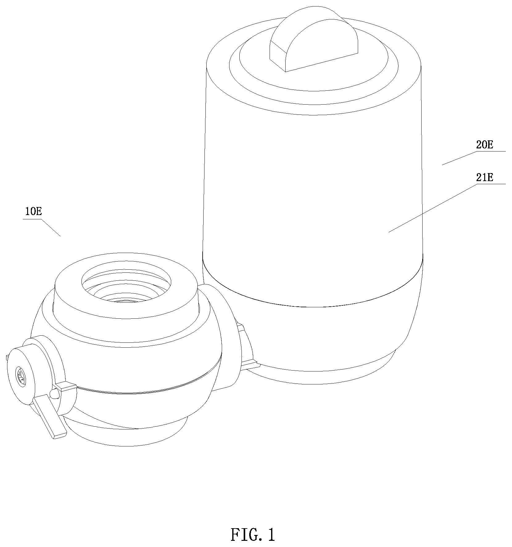
is a front view of the faucet water purifier according to a first embodiment of the present invention.
is an exploded view of the faucet water purifier according to the above first embodiment of the present invention.
A is a front view of the filtering device of the faucet water purifier according to the above first embodiment of the present invention.
B is a sectional view of the filtering device of the faucet water purifier according to the above first embodiment of the present invention.
C is another sectional view of the filtering device of the faucet water purifier according to the above first embodiment of the present invention, which shows a brush of the filtering device.
D is a perspective view of a primary filter of the filtering device of the faucet water purifier according to the above first embodiment of the present invention.
E is a perspective view of a secondary filter of the filtering device of the faucet water purifier according to the above first embodiment of the present invention.
A is a perspective view of a base of the filtering device of the faucet water purifier according to the above first embodiment of the present invention.
B is a sectional view of the base of the filtering device of the faucet water purifier according to the above first embodiment of the present invention.
C is another sectional view of the base of the filtering device of the faucet water purifier according to the above first embodiment of the present invention.
D is another sectional view of the base of the filtering device of the faucet water purifier according to the above first embodiment of the present invention.
E is another sectional view of the base of the filtering device of the faucet water purifier according to the above first embodiment of the present invention.
A is a sectional view of the base and a terminal filter of the filtering device of the faucet water purifier according to the above first embodiment of the present invention.
B is a perspective view of the terminal filter of the filtering device of the faucet water purifier according to the above first embodiment of the present invention.
C is a sectional view of the terminal filter of the filtering device of the faucet water purifier according to the above first embodiment of the present invention.
A is a perspective view of a plane valve of the faucet water purifier according to the above first embodiment of the present invention, which shows a first channel, a second channel, a third channel, a fourth channel, a fifth channel, a ninth channel and a draining channel of the plane valve.
B is another perspective view of the plane valve of the faucet water purifier according to the above first embodiment of the present invention, which shows the first channel, the second channel, the third channel, the fourth channel, the fifth channel, the ninth channel, the draining channel and a second seal of the plane valve.
C is another perspective view of the plane valve of the faucet water purifier according to the above first embodiment of the present invention, which shows a first opening, a second opening, a fourth opening and a fifth opening of the valve body.
D is another perspective view of the plane valve of the faucet water purifier according to the above first embodiment of the present invention, which shows a raw water inlet of the valve body.
E is another perspective view of the plane valve of the faucet water purifier according to the above first embodiment of the present invention, which shows a third opening, a raw water opening and a draining opening of the valve body.
F is a top view of the valve body of the plane valve of the faucet water purifier according to the above first embodiment of the present invention.
G is a bottom view of the valve body of the plane valve of the faucet purifier according to the above first embodiment of the present invention.
H is a front view of the valve body of the plane valve of the faucet purifier according to the above first embodiment of the present invention.
I is a perspective view of the valve body of the plane valve of the faucet water purifier according to the above first embodiment of the present invention.
A is a sectional view of the valve body of the plane valve of the faucet water purifier according to the above first embodiment of the present invention, which shows the first channel and the first opening of the plane valve.
B is another sectional view of the valve body of the plane valve of the faucet water purifier according to the above first embodiment of the present invention, which shows the second channel, the fourth channel, the second opening and the fourth opening of the plane valve.
C is another sectional view of the valve body of the plane valve of the faucet water purifier according to the above first embodiment of the present invention, which shows the third channel, the fifth channel, the third opening and the fifth opening of the plane valve.
D is another sectional view of the valve body of the plane valve of the faucet water purifier according to the above first embodiment of the present invention, which shows the ninth channel and the raw water opening of the plane valve.
E is another sectional view of the valve body of the plane valve of the faucet water purifier according to the above first embodiment of the present invention, which shows the draining channel and the draining opening of the plane valve.
A is a sectional view of the plane valve of the faucet water purifier according to the above first embodiment of the present invention, wherein a fixing device is disposed inside the valve cavity of the plane valve.
B is a perspective view of the valve body of the plane valve of the faucet water purifier according to the above first embodiment of the present invention, wherein a guiding plate of the faucet water purifier of the present invention is provided at the valve body of the plane valve.
C is a perspective view of the guiding plate of the faucet water purifier according to the above first embodiment of the present invention.
D is another perspective view of the guiding plate of the faucet water purifier according to the above first embodiment of the present invention.
A is a perspective view of the fixing device of the faucet water purifier according to the above first embodiment of the present invention.
B is a sectional view of the fixing device of the faucet water purifier according to the above first embodiment of the present invention.
C is a perspective view of a fixing portion of a fixed disk of the plane valve of the faucet water purifier according to the above first embodiment of the present invention, which shows first sealing groove of the fixing portion.
D is another perspective view of the fixing portion of the fixed disk of the plane valve of the faucet water purifier according to the above first embodiment of the present invention, which shows second sealing groove of the fixing portion.
E shows the fixing portion of the fixed disk of the plane valve of the faucet water purifier according to the above first embodiment of the present invention, wherein an upper end portion of the fixed disk is provided at the fixing portion.
F is a perspective view of a first seal of a sealing assembly of the faucet water purifier according to the above first embodiment of the present invention.
G is a perspective view of the second seal of the sealing assembly of the faucet water purifier according to the above first embodiment of the present invention.
H is a perspective view of a fixing holder of the fixing device of the faucet water purifier according to the above first embodiment of the present invention, which shows restricting grooves of the fixing holder.
A is a perspective view of the fixed disk of the plane valve of the faucet water purifier according to the above first embodiment of the present invention.
B is a top view of the fixed disk of the plane valve of the faucet water purifier according to the above first embodiment of the present invention.
C is a bottom view of the fixed disk of the plane valve of the faucet water purifier according to the above first embodiment of the present invention.
D is a perspective view of a rotatable disk of the plane valve of the faucet water purifier according to the above first embodiment of the present invention.
E is a top view of the rotatable disk of the plane valve of the faucet water purifier according to the above first embodiment of the present invention.
F is a bottom view of the rotatable disk of the plane valve of the faucet water purifier according to the above first embodiment of the present invention.
A is a structure diagram of the faucet water purifier according to the above first embodiment of the present invention, wherein the faucet water purifier shown in A is under a first purifying working state, and the arrows shown in A respectively point to the directions of water flow.
B is a structure diagram of the faucet water purifier according to the above first embodiment of the present invention, wherein the faucet water purifier shown in B is under a back flushing working state, and the arrows shown in B respectively point to the directions of water flow.
C is a structure diagram of the faucet water purifier according to the above first embodiment of the present invention, wherein the faucet water purifier shown in the drawing is under a raw water supplying working state, and the arrows in the drawing point to the direction of water flow.
D is a structure diagram of the faucet water purifier according to the above first embodiment of the present invention, wherein the faucet water purifier shown in D is under a second purifying working state, and the arrows shown in D point to the direction of water flow.
A is a structure diagram of the fixed disk of the plane valve of the faucet water purifier according to the above first embodiment of the present invention.
B is a structure diagram of the rotatable disk of the plane valve of the faucet water purifier according to the above first embodiment of the present invention, wherein the dotted line shown in B shows a communicating channel of the rotatable disk.
C is a diagram of the equal division of the fixed disk of the plane valve of the faucet water purifier according to the above first embodiment of the present invention, which shows channels are provided in the specific equal division positions of the fixed disk.
D is a diagram of the equal division of the rotatable disk of the plane valve of the faucet water purifier according to the above first embodiment of the present invention, which shows channels are provided in the specific equal division positions of the rotatable disk.
A is a diagram of the communication between the channels of the rotatable disk and the channels of the fixed disk of the plane valve, when the plane valve of the faucet water purifier according to the above first embodiment of the present invention is under a first purifying working position, wherein the shaded area shown in A shows the passages defined by the communication between the rotatable disk and the fixed disk of the plane valve.
B is a diagram of the communication between the channels of the rotatable disk and the channels of the fixed disk of the plane valve, when the plane valve of the faucet water purifier according to the above first embodiment of the present invention is under a back-flushing working position, wherein the shaded area shown in B shows the passages defined by the communication between the rotatable disk and the fixed disk of the plane valve.
C is a diagram of the communication between the channels of the rotatable disk and the channels of the fixed disk of the plane valve, when the plane valve of the faucet water purifier according to the above first embodiment of the present invention is under a raw water supplying working position, wherein the shaded area shown in C shows the passages defined by the communication between the rotatable disk and the fixed disk of the plane valve.
D is a diagram of the communication between the channels of the rotatable disk and the channels of the fixed disk of the plane valve, when the plane valve of the faucet water purifier according to the above first embodiment of the present invention is under a second purifying working position, wherein the shaded area shown in D shows the passages defined by the communication between the rotatable disk and the fixed disk of the plane valve.
A is a front view of an alternative embodiment of the filtering device of the faucet water purifier according to the above first embodiment of the present invention.
B is a sectional view of the alternative embodiment of the filtering device of the faucet water purifier according to the above first embodiment of the present invention.
C is another sectional view of the alternative embodiment of the filtering device of the faucet water purifier according to the above first embodiment of the present invention, which shows a brush of the filtering device.
D is a perspective view of a primary filter of the alternative embodiment of the filtering device of the faucet water purifier according to the above first embodiment of the present invention.
E is a perspective view of a secondary filter of the alternative embodiment of the filtering device of the faucet water purifier according to the above first embodiment of the present invention.
A is a perspective view of a base of the alternative embodiment of the filtering device of the faucet water purifier according to the above first embodiment of the present invention.
B is a sectional view of the base of the alternative embodiment of the filtering device of the faucet water purifier according to the above first embodiment of the present invention.
C is another sectional view of the base of the alternative embodiment of the filtering device of the faucet water purifier according to the above first embodiment of the present invention.
D is another sectional view of the base of the alternative embodiment of the filtering device of the faucet water purifier according to the above first embodiment of the present invention.
E is another sectional view of the base of the alternative embodiment of the filtering device of the faucet water purifier according to the above first embodiment of the present invention.
is an exploded view of an alternative embodiment of the control valve of the faucet water purifier according to the above first embodiment of the present invention.
A is a perspective view of the alternative embodiment of the plane valve of the faucet water purifier according to the above first embodiment of the present invention, which shows a first channel, a second channel, a third channel, a fourth channel, a fifth channel, a ninth channel and a raw water inlet channel of the plane valve.
B is another perspective view of the alternative embodiment of the plane valve of the faucet water purifier according to the above first embodiment of the present invention, which shows the first channel, the second channel, the third channel, the fourth channel, the fifth channel, the ninth channel, the raw water inlet channel and a second seal of the plane valve.
C is another perspective view of the alternative embodiment of the plane valve of the faucet water purifier according to the above first embodiment of the present invention, which shows a first opening, a second opening, a fourth opening and a fifth opening of the valve body.
D is another perspective view of the alternative embodiment of the plane valve of the faucet water purifier according to the above first embodiment of the present invention, which shows a raw water inlet of the valve body.
E is another perspective view of the alternative embodiment of the plane valve of the faucet water purifier according to the above first embodiment of the present invention, which shows a third opening, a raw water opening and a draining opening of the valve body.
F is a top view of the alternative embodiment of the plane valve of the faucet water purifier according to the above first embodiment of the present invention.
G is a bottom view of the alternative embodiment of the plane valve of the faucet water purifier according to the above first embodiment of the present invention.
H is a front view of the alternative embodiment of the plane valve of the faucet water purifier according to the above first embodiment of the present invention.
I is another front view of the alternative embodiment of the plane valve of the faucet water purifier according to the above first embodiment of the present invention.
A is a sectional view of the alternative embodiment of the plane valve of the faucet water purifier according to the above first embodiment of the present invention, which shows the first channel and the first opening of the plane valve.
B is another sectional view of the alternative embodiment of the plane valve of the faucet water purifier according to the above first embodiment of the present invention, which shows the second channel, the fourth channel, the second opening and the fourth opening.
C is another sectional view of the alternative embodiment of the plane valve of the faucet water purifier according to the above first embodiment of the present invention, which shows the third channel, the fifth channel, the third opening, the fifth opening and the draining opening of the plane valve, wherein the draining opening is communicated with the valve cavity.
D is another sectional view of the alternative embodiment of the plane valve of the faucet water purifier according to the above first embodiment of the present invention, which shows the ninth channel and the raw water opening of the plane valve.
E is another sectional view of the alternative embodiment of the plane valve of the faucet water purifier according to the above first embodiment of the present invention, which shows the raw water inlet and the raw water inlet channel of the plane valve.
A is another sectional view of the alternative embodiment of the plane valve of the faucet water purifier according to the above first embodiment of the present invention, wherein the fixing device is disposed inside the valve cavity of the plane valve.
B is a perspective view of the alternative embodiment of the plane valve of the faucet water purifier according to the above first embodiment of the present invention, wherein the guiding plate of the faucet water purifier of the present invention is provided at the valve body of the plane valve.
C is a perspective view of the guiding plate of the alternative embodiment of the plane valve of the faucet water purifier according to the above first embodiment of the present invention.
D is another perspective view of the guiding plate of the alternative embodiment of the plane valve of the faucet water purifier according to the above first embodiment of the present invention.
A is a perspective view of the fixing device of the alternative embodiment of the plane valve of the faucet water purifier according to the above first embodiment of the present invention.
B is a sectional view of the fixing device of the alternative embodiment of the plane valve of the faucet water purifier according to the above first embodiment of the present invention.
C is a perspective view of the fixing portion of the fixed disk of the alternative embodiment of the plane valve of the faucet water purifier according to the above second embodiment of the present invention, which shows the first sealing grooves of the fixing portion.
D is another perspective view of the fixing portion of the fixed disk of the alternative embodiment of the plane valve of the faucet water purifier according to the above first embodiment of the present invention, which shows the second sealing grooves of the fixing portion.
E is a perspective view of the upper end portion of the fixed disk of the alternative embodiment of the plane valve of the faucet water purifier according to the above first embodiment of the present invention, wherein the upper end portion of the fixed disk is provided at the fixing portion of the fixed disk.
F is a perspective view of the first seal of the sealing assembly of the alternative embodiment of the plane valve of the faucet water purifier according to the above first embodiment of the present invention.
G is a perspective view of the second seal of the sealing assembly of the alternative embodiment of the plane valve of the faucet water purifier according to the above first embodiment of the present invention.
H is a perspective view of a fixing holder of the fixing device of the alternative embodiment of the plane valve of the faucet water purifier according to the above first embodiment of the present invention, which shows the restricting grooves of the fixing holder.
A is a perspective view of the fixed disk of the alternative embodiment of the plane valve of the faucet water purifier according to the above first embodiment of the present invention.
B is a top view of the fixed disk of the alternative embodiment of the plane valve of the faucet water purifier according to the above first embodiment of the present invention.
C is a bottom view of the fixed disk of the alternative embodiment of the plane valve of the faucet water purifier according to the above first embodiment of the present invention.
D is a perspective view of the rotatable disk of the alternative embodiment of the plane valve of the faucet water purifier according to the above first embodiment of the present invention.
E is a top view of the rotatable disk of the alternative embodiment of the plane valve of the faucet water purifier according to the above first embodiment of the present invention.
F is a bottom view of the rotatable disk of the alternative embodiment of the plane valve of the faucet water purifier according to the above first embodiment of the present invention.
A is a structure diagram of the alternative embodiment of the plane valve of the faucet water purifier according to the above first embodiment of the present invention, wherein the faucet water purifier shown in A is under a first purifying working state, and the arrows shown in A point to the direction of water flow.
B is a structure diagram of the alternative embodiment of the plane valve of the faucet water purifier according to the above first embodiment of the present invention, wherein the faucet water purifier shown in B is under a back flushing working state, and the arrows shown in B point to the direction of water flow.
C is a structure diagram of the alternative embodiment of the faucet water purifier according to the above first embodiment of the present invention, wherein the faucet water purifier shown in B is under a raw water supplying working state, and the arrows shown in C point to the direction of water flow.
D is a structure diagram of the alternative embodiment of the faucet water purifier according to the above first embodiment of the present invention, wherein the faucet water purifier shown in D is under a second purifying working state, and the arrows shown in D point to the direction of water flow.
A is a structure diagram of the fixed disk of the alternative embodiment of the plane valve of the faucet water purifier according to the above first embodiment of the present invention.
B is a structure diagram of the rotatable disk of the alternative embodiment of the plane valve of the faucet water purifier according to the above first embodiment of the present invention, wherein the dotted line shown in B shows the communicating channels of the rotatable disk.
C is a diagram of the equal divisions of the fixed disk of the alternative embodiment of the plane valve of the faucet water purifier according to the above first embodiment of the present invention, which shows that the channels are respectively provided in the specific equal divisions of the fixed disk.
D is a diagram of the equal divisions of the rotatable disk of the alternative embodiment of the plane valve of the faucet water purifier according to the above first embodiment of the present invention, which shows that the channels are respectively provided in the specific equal divisions of the rotatable disk.
A is a diagram of the communication between the channels of the rotatable disk and the channels of the fixed disk of the plane valve, when the alternative embodiment of the plane valve of the faucet water purifier according to the above first embodiment of the present invention is under a first purifying working position, wherein the shaded area shown in A shows the passages defined by the communication between the rotatable disk and the fixed disk of the plane valve.
B is a diagram of the communication between the channels of the rotatable disk and the channels of the fixed disk of the plane valve, when the alternative embodiment of the plane valve of the faucet water purifier according to the above first embodiment of the present invention is under a back flushing working position, wherein the shaded area shown in B shows the passages defined by the communication between the rotatable disk and the fixed disk of the plane valve.
C is a diagram of the communication between the channels of the rotatable disk and the channels of the fixed disk of the plane valve, when the alternative embodiment of the plane valve of the faucet water purifier according to the above first embodiment of the present invention is under a raw water supplying working position, wherein the shaded area shown in C shows the passages defined by the communication between the rotatable disk and the fixed disk of the plane valve.
D is a diagram of the communication between the channels of the rotatable disk and the channels of the fixed disk of the plane valve, when the alternative embodiment of the plane valve of the faucet water purifier according to the above first embodiment of the present invention is under a second purifying working position, wherein the shaded area shown in D shows the passages defined by the communication between the rotatable disk and the fixed disk of the plane valve.
is an exploded view of another alternative embodiment of the control valve of the faucet water purifier according to the above first embodiment of the present invention.
A is a perspective view of the alternative embodiment of the plane valve of the faucet water purifier according to the above first embodiment of the present invention, which shows a first channel, a second channel, a third channel, a fourth channel, a fifth channel, an eighth channel and a ninth channel of the plane valve.
B is another perspective view of the alternative embodiment of the plane valve of the faucet water purifier according to the above first embodiment of the present invention, which shows the first channel, the second channel, the third channel, the fourth channel, the fifth channel, the eighth channel, the ninth channel and a second seal of the plane valve.
C is another perspective view of the alternative embodiment of the plane valve of the faucet water purifier according to the above first embodiment of the present invention, which shows a first opening, a second opening, a fourth opening and a fifth opening of the valve body.
D is another perspective view of the alternative embodiment of the plane valve of the faucet water purifier according to the above first embodiment of the present invention, which shows a raw water inlet of the valve body.
E is another perspective view of the alternative embodiment of the plane valve of the faucet water purifier according to the above first embodiment of the present invention, which shows a third opening, a raw water opening and a draining opening of the valve body.
F is a top view of the alternative embodiment of the plane valve of the faucet water purifier according to the above first embodiment of the present invention.
G is a bottom view of the alternative embodiment of the plane valve of the faucet water purifier according to the above first embodiment of the present invention.
H is a front view of the alternative embodiment of the plane valve of the faucet water purifier according to the above first embodiment of the present invention.
I is another front view of the alternative embodiment of the plane valve of the faucet water purifier according to the above first embodiment of the present invention.
A is a sectional view of the alternative embodiment of the plane valve of the faucet water purifier according to the above first embodiment of the present invention, which shows the first channel, the first opening, the third channel and the third opening of the plane valve.
B is another sectional view of the alternative embodiment of the plane valve of the faucet water purifier according to the above first embodiment of the present invention, which shows the second channel and the second opening of the plane valve.
C is another sectional view of the alternative embodiment of the plane valve of the faucet water purifier according to the above first embodiment of the present invention, which shows the fourth channel, the fourth opening, the fifth channel and the fifth opening of the plane valve.
D is another sectional view of the alternative embodiment of the plane valve of the faucet water purifier according to the above first embodiment of the present invention, which shows the eighth channel and the draining opening of the plane valve.
E is another sectional view of the alternative embodiment of the plane valve of the faucet water purifier according to the above first embodiment of the present invention, which shows the ninth channel and the raw water opening of the plane valve.
A is another sectional view of the alternative embodiment of the plane valve of the faucet water purifier according to the above first embodiment of the present invention, wherein the fixing device is disposed inside the valve cavity of the plane valve.
B is a perspective view of the alternative embodiment of the plane valve of the faucet water purifier according to the above first embodiment of the present invention, wherein the guiding plate of the faucet water purifier of the present invention is provided at the valve body of the plane valve.
C is a perspective view of the guiding plate of the alternative embodiment of the plane valve of the faucet water purifier according to the above first embodiment of the present invention.
D is another perspective view of the guiding plate of the alternative embodiment of the plane valve of the faucet water purifier according to the above first embodiment of the present invention.
A is a perspective view of the fixing device of the alternative embodiment of the plane valve of the faucet water purifier according to the above first embodiment of the present invention.
B is a sectional view of the fixing device of the alternative embodiment of the plane valve of the faucet water purifier according to the above first embodiment of the present invention.
C is a perspective view of the fixing portion of the fixed disk of the alternative embodiment of the plane valve of the faucet water purifier according to the above second embodiment of the present invention, which shows the first sealing grooves of the fixing portion.
D is another perspective view of the fixing portion of the fixed disk of the alternative embodiment of the plane valve of the faucet water purifier according to the above first embodiment of the present invention, which shows the second sealing grooves of the fixing portion.
E is a perspective view of the upper end portion of the fixed disk of the alternative embodiment of the plane valve of the faucet water purifier according to the above first embodiment of the present invention, wherein the upper end portion of the fixed disk is provided at the fixing portion of the fixed disk.
F is a perspective view of the first seal of the sealing assembly of the alternative embodiment of the plane valve of the faucet water purifier according to the above first embodiment of the present invention.
G is a perspective view of the second seal of the sealing assembly of the alternative embodiment of the plane valve of the faucet water purifier according to the above first embodiment of the present invention.
H is a perspective view of a fixing holder of the fixing device of the alternative embodiment of the plane valve of the faucet water purifier according to the above first embodiment of the present invention, which shows the restricting grooves of the fixing holder.
A is a perspective view of the fixed disk of the alternative embodiment of the plane valve of the faucet water purifier according to the above first embodiment of the present invention.
B is a top view of the fixed disk of the alternative embodiment of the plane valve of the faucet water purifier according to the above first embodiment of the present invention.
C is a bottom view of the fixed disk of the alternative embodiment of the plane valve of the faucet water purifier according to the above first embodiment of the present invention.
D is a perspective view of the rotatable disk of the alternative embodiment of the plane valve of the faucet water purifier according to the above first embodiment of the present invention.
E is a top view of the rotatable disk of the alternative embodiment of the plane valve of the faucet water purifier according to the above first embodiment of the present invention.
F is a bottom view of the rotatable disk of the alternative embodiment of the plane valve of the faucet water purifier according to the above first embodiment of the present invention.
A is a structure diagram of the alternative embodiment of the faucet water purifier according to the above first embodiment of the present invention, wherein the faucet water purifier shown in A is under a first purifying working state, and the arrows shown in A point to the direction of water flow.
B is a structure diagram of the alternative embodiment of the faucet water purifier according to the above first embodiment of the present invention, wherein the faucet water purifier shown in B is under a back flushing working state, and the arrows shown in B point to the direction of water flow.
C is a structure diagram of the alternative embodiment of the faucet water purifier according to the above first embodiment of the present invention, wherein the faucet water purifier shown in C is under a raw water supplying working state, and the arrows shown in C point to the direction of water flow.
D is a structure diagram of the alternative embodiment of the faucet water purifier according to the above first embodiment of the present invention, wherein the faucet water purifier shown in D is under a second purifying working state, and the arrows shown in D point to the direction of water flow.
A is a structure diagram of the fixed disk of the alternative embodiment of the plane valve of the faucet water purifier according to the above first embodiment of the present invention.
B is a structure diagram of the rotatable disk of the alternative embodiment of the plane valve of the faucet water purifier according to the above first embodiment of the present invention, wherein the dotted lines shown in B show the communicating channels of the rotatable disk.
C is a diagram of the equal divisions of the fixed disk of the alternative embodiment of the plane valve of the faucet water purifier according to the above first embodiment of the present invention, which shows that the channels are respectively provided in the specific equal divisions of the fixed disk.
D is a diagram of the equal divisions of the rotatable disk of the alternative embodiment of the plane valve of the faucet water purifier according to the above first embodiment of the present invention, which shows that the channels are respectively provided in the specific equal divisions of the rotatable disk.
A is a diagram of the communication between the channels of the rotatable disk and the channels of the fixed disk of the plane valve, when the alternative embodiment of the plane valve of the faucet water purifier according to the above first embodiment of the present invention is under a first purifying working position, wherein the shaded area shown in A shows the passages defined by the communication between of the rotatable disk and the fixed disk of the plane valve.
B is a diagram of the communication between the channels of the rotatable disk and the channels of the fixed disk of the plane valve, when the alternative embodiment of the plane valve of the faucet water purifier according to the above first embodiment of the present invention is under a back flushing working position, wherein the shaded area shown in B shows the passages defined by the communication between the rotatable disk and the fixed disk of the plane valve.
C is a diagram of the communication between the channels of the rotatable disk and the channels of the fixed disk of the plane valve, when the alternative embodiment of the plane valve of the faucet water purifier according to the above first embodiment of the present invention is under a raw water supplying working position, wherein the shaded area shown in C shows the passages defined by the communication between the rotatable disk and the fixed disk of the plane valve.
D is a diagram of the communication between the channels of the rotatable disk and the channels of the fixed disk of the plane valve, when the alternative embodiment of the plane valve of the faucet water purifier according to the above first embodiment of the present invention is under a second purifying working position, wherein the shaded area shown in D shows the passages defined by the communication between the rotatable disk and the fixed disk of the plane valve.
is an exploded view of another alternative embodiment of the control valve of the faucet water purifier according to the above first embodiment of the present invention.
A is a perspective view of the alternative embodiment of the plane valve of the faucet water purifier according to the above first embodiment of the present invention, which shows a first channel, a second channel, a third channel, a fourth channel, a fifth channel, an eighth channel, a ninth channel and a raw water inlet channel of the plane valve.
B is another perspective view of the alternative embodiment of the plane valve of the faucet water purifier according to the above first embodiment of the present invention, which shows the first channel, the second channel, the third channel, the fourth channel, the fifth channel, the eighth channel, the ninth channel, the raw water inlet channel and a second seal of the plane valve.
C is another perspective view of the alternative embodiment of the plane valve of the faucet water purifier according to the above first embodiment of the present invention, which shows a first opening, a second opening, a fourth opening and a fifth opening of the valve body.
D is another perspective view of the alternative embodiment of the plane valve of the faucet water purifier according to the above first embodiment of the present invention, which shows a raw water inlet of the valve body.
E is another perspective view of the alternative embodiment of the plane valve of the faucet water purifier according to the above first embodiment of the present invention, which shows a third opening, a raw water opening and a draining opening of the valve body.
F is a top view of the alternative embodiment of the plane valve of the faucet water purifier according to the above first embodiment of the present invention.
G is a bottom view of the alternative embodiment of the plane valve of the faucet water purifier according to the above first embodiment of the present invention.
H is a front view of the alternative embodiment of the plane valve of the faucet water purifier according to the above first embodiment of the present invention.
I is another front view of the alternative embodiment of the plane valve of the faucet water purifier according to the above first embodiment of the present invention.
A is a sectional view of the alternative embodiment of the plane valve of the faucet water purifier according to the above first embodiment of the present invention, which shows the first channel and the first opening of the plane valve.
B is another sectional view of the alternative embodiment of the plane valve of the faucet water purifier according to the above first embodiment of the present invention, which shows the second channel and the second opening of the plane valve.
C is another sectional view of the alternative embodiment of the plane valve of the faucet water purifier according to the above first embodiment of the present invention, which shows the third channel and the third opening of the plane valve.
D is another sectional view of the alternative embodiment of the plane valve of the faucet water purifier according to the above first embodiment of the present invention, which shows the fourth channel, the fourth opening, the fifth channel and the fifth opening of the plane valve.
E is another sectional view of the alternative embodiment of the plane valve of the faucet water purifier according to the above first embodiment of the present invention, which shows the eighth channel and the draining opening of the plane valve.
F is another sectional view of the alternative embodiment of the plane valve of the faucet water purifier according to the above first embodiment of the present invention, which shows the ninth channel and the raw water opening of the plane valve.
G is another sectional view of the alternative embodiment of the plane valve of the faucet water purifier according to the above first embodiment of the present invention, which shows the raw water inlet channel and the raw water inlet of the plane valve.
A is another sectional view of the alternative embodiment of the plane valve of the faucet water purifier according to the above first embodiment of the present invention, wherein the fixing device is disposed inside the valve cavity of the plane valve.
B is a perspective view of the alternative embodiment of the plane valve of the faucet water purifier according to the above first embodiment of the present invention, wherein the guiding plate of the faucet water purifier of the present invention is provided at the valve body of the plane valve.
C is a perspective view of the guiding plate of the alternative embodiment of the plane valve of the faucet water purifier according to the above first embodiment of the present invention.
D is another perspective view of the guiding plate of the alternative embodiment of the plane valve of the faucet water purifier according to the above first embodiment of the present invention.
A is a perspective view of the fixing device of the alternative embodiment of the plane valve of the faucet water purifier according to the above first embodiment of the present invention.
B is a sectional view of the fixing device of the alternative embodiment of the plane valve of the faucet water purifier according to the above first embodiment of the present invention.
C is a perspective view of the fixing portion of the fixed disk of the alternative embodiment of the plane valve of the faucet water purifier according to the above first embodiment of the present invention, which shows the first sealing grooves of the fixing portion.
D is another perspective view of the fixing portion of the fixed disk of the alternative embodiment of the plane valve of the faucet water purifier according to the above first embodiment of the present invention, which shows the second sealing grooves of the fixing portion.
E is a perspective view of the upper end portion of the fixed disk of the alternative embodiment of the plane valve of the faucet water purifier according to the above first embodiment of the present invention, wherein the upper end portion of the fixed disk is provided at the fixing portion of the fixed disk.
F is a perspective view of the first seal of the sealing assembly of the alternative embodiment of the plane valve of the faucet water purifier according to the above first embodiment of the present invention.
G is a perspective view of the second seal of the sealing assembly of the alternative embodiment of the plane valve of the faucet water purifier according to the above first embodiment of the present invention.
H is a perspective view of a fixing holder of the fixing device of the alternative embodiment of the plane valve of the faucet water purifier according to the above first embodiment of the present invention, which shows the restricting grooves of the fixing holder.
A is a perspective view of the fixed disk of the alternative embodiment of the plane valve of the faucet water purifier according to the above first embodiment of the present invention.
B is a top view of the fixed disk of the alternative embodiment of the plane valve of the faucet water purifier according to the above first embodiment of the present invention.
C is a bottom view of the fixed disk of the alternative embodiment of the plane valve of the faucet water purifier according to the above first embodiment of the present invention.
D is a perspective view of the rotatable disk of the alternative embodiment of the plane valve of the faucet water purifier according to the above first embodiment of the present invention.
E is a top view of the rotatable disk of the alternative embodiment of the plane valve of the faucet water purifier according to the above first embodiment of the present invention.
F is a bottom view of the rotatable disk of the alternative embodiment of the plane valve of the faucet water purifier according to the above first embodiment of the present invention.
A is a structure diagram of the alternative embodiment of the faucet water purifier according to the above first embodiment of the present invention, wherein the faucet water purifier shown in A is under a first purifying working state, and the arrows shown in A point to the direction of water flow.
B is a structure diagram of the alternative embodiment of the faucet water purifier according to the above first embodiment of the present invention, wherein the faucet water purifier shown in B is under a back flushing working state, and the arrows shown in B point to the direction of water flow.
C is a structure diagram of the alternative embodiment of the faucet water purifier according to the above first embodiment of the present invention, wherein the faucet water purifier shown in C is under a raw water supplying working state, and the arrows shown in C point to the direction of water flow.
D is a structure diagram of the alternative embodiment of the faucet water purifier according to the above first embodiment of the present invention, wherein the faucet water purifier shown in D is under a second purifying working state, and the arrows shown in D point to the direction of water flow.
A is a structure diagram of the fixed disk of the alternative embodiment of the plane valve of the faucet water purifier according to the above first embodiment of the present invention.
B is a structure diagram of the rotatable disk of the alternative embodiment of the plane valve of the faucet water purifier according to the above first embodiment of the present invention, wherein the dotted lines shown in B show the communicating channels of the rotatable disk.
C is a diagram of the equal divisions of the fixed disk of the alternative embodiment of the plane valve of the faucet water purifier according to the above first embodiment of the present invention, which shows that the channels are respectively provided in the specific equal divisions of the fixed disk.
D is a diagram of the equal divisions of the rotatable disk of the alternative embodiment of the plane valve of the faucet water purifier according to the above first embodiment of the present invention, which shows that the channels are respectively provided in the specific equal divisions of the rotatable disk.
A is a diagram of the communication between the channels of the rotatable disk and the channels of the fixed disk of the plane valve, when the alternative embodiment of the plane valve of the faucet water purifier according to the above first embodiment of the present invention is under a first purifying working position, wherein the shaded area shown in A shows the passages defined by the communication between the rotatable disk and the fixed disk of the plane valve.
B is a diagram of the communication between the channels of the rotatable disk and the channels of the fixed disk of the plane valve, when the alternative embodiment of the plane valve of the faucet water purifier according to the above first embodiment of the present invention is under a back flushing working position, wherein the shaded area shown in B shows the passages defined by the communication between the rotatable disk and the fixed disk of the plane valve.
C is a diagram of the communication between the channels of the rotatable disk and the channels of the fixed disk of the plane valve, when the alternative embodiment of the plane valve of the faucet water purifier according to the above first embodiment of the present invention is under a raw water supplying working position, wherein the shaded area shown in C shows the passages defined by the communication between the rotatable disk and the fixed disk of the plane valve.
D is a diagram of the communication between the channels of the rotatable disk and the channels of the fixed disk of the plane valve, when the alternative embodiment of the plane valve of the faucet water purifier according to the above first embodiment of the present invention is under a second purifying working position, wherein the shaded area shown in D shows the passages defined by the communication between the rotatable disk and the fixed disk of the plane valve.
is a front view of the faucet water purifier according to a second embodiment of the present invention.
is an exploded view of the faucet water purifier according to the above second embodiment of the present invention.
A is a front view of the filtering device of the faucet water purifier according to the above second embodiment of the present invention.
B is a sectional view of the filtering device of the faucet water purifier according to the above second embodiment of the present invention.
C is a perspective view of a primary filter of the filtering device of the faucet water purifier according to the above second embodiment of the present invention.
D is a perspective view of a secondary filter of the filtering device of the faucet water purifier according to the above second embodiment of the present invention.
A is a perspective view of a base of the filtering device of the faucet water purifier according to the above second embodiment of the present invention.
B is a sectional view of the base of the filtering device of the faucet water purifier according to the above second embodiment of the present invention.
C is another sectional view of the base of the filtering device of the faucet water purifier according to the above second embodiment of the present invention.
D is another sectional view of the base of the filtering device of the faucet water purifier according to the above second embodiment of the present invention.
E is another sectional view of the base of the filtering device of the faucet water purifier according to the above second embodiment of the present invention.
A is a sectional view of the base and a terminal filter of the filtering device of the faucet water purifier according to the above second embodiment of the present invention.
B is a sectional view of the terminal filter of the filtering device of the faucet water purifier according to the above second embodiment of the present invention.
C is another sectional view of the terminal filter of the filtering device of the faucet water purifier according to the above second embodiment of the present invention.
A is a front view of an alternative embodiment of the filtering device of the faucet water purifier according to the above second embodiment of the present invention.
B is a sectional view of the alternative embodiment of the filtering device of the faucet water purifier according to the above second embodiment of the present invention.
C is a perspective view of the secondary filter of the alternative embodiment of the filtering device of the faucet water purifier according to the above second embodiment of the present invention.
D is a sectional view of the secondary filter of the alternative embodiment of the filtering device of the faucet water purifier according to the above second embodiment of the present invention.
A is a perspective view of the base of the alternative embodiment of the filtering device of the faucet water purifier according to the above second embodiment of the present invention.
B is a sectional view of the base of the alternative embodiment of the filtering device of the faucet water purifier according to the above second embodiment of the present invention.
C is another sectional view of the base of the alternative embodiment of the filtering device of the faucet water purifier according to the above second embodiment of the present invention.
D is another sectional view of the base of the alternative embodiment of the filtering device of the faucet water purifier according to the above second embodiment of the present invention.
E is another sectional view of the base of the alternative embodiment of the filtering device of the faucet water purifier according to the above second embodiment of the present invention.
DETAILED DESCRIPTION OF THE PREFERRED EMBODIMENT
The following description is disclosed to enable any person skilled in the art to make and use the present invention. Preferred embodiments are provided in the following description only as examples and modifications will be apparent to those skilled in the art. The general principles defined in the following description would be applied to other embodiments, alternatives, modifications, equivalents, and applications without departing from the spirit and scope of the present invention.
Those skilled in the art should understand that, in the disclosure of the present invention, terminologies of “longitudinal”, “lateral”, “upper”, “lower”, “front”, “back”, “left”, “right”, “perpendicular”, “horizontal”, “top”, “bottom”, “inner”, “outer” and etc. just indicate relations of direction or position are based on the relations of direction or position shown in the appended drawings, which is only to facilitate descriptions of the present invention and to simplify the descriptions, rather than to indicate or imply that the referred device or element must apply specific direction or to be operated or configured in specific direction. Therefore, the above-mentioned terminologies shall not be interpreted as confine to the present invention.
It will be understood that the term “a” should be understood as “at least one” or “one or more”, that is, in one embodiment, the number of an element may be one, and in other embodiments, the number of the element can be greater than one, and the term “a” cannot be construed as a limitation to the quantity.
Referring to to D , a faucet water purifier of a first embodiment of the present invention is illustrated, wherein the faucet water purifier of the present invention comprises a control valve 10 E and a filtering device 20 E, wherein the control valve 10 E is provided for controlling the flow of water, such as controlling the supply of raw water (or tap water) to be supplied to the filtering device 20 E and controlling the supply of the purified water generated or produced by treating the raw water by the filtering device 20 E.
As shown in to C , the filtering device 20 E of the faucet water purifier according to the first embodiment of the present invention comprises an outer casing 21 E, a primary filter 22 E and a secondary filter 23 E, wherein the outer casing 21 E defines a first accommodation cavity 210 E, the primary filter 22 E defines a second accommodation cavity 220 E, wherein the primary filter 22 E is disposed inside the first accommodation cavity 210 E of the outer casing 21 E, the secondary filter 23 E is disposed inside the second accommodation cavity 220 E of the primary filter 22 E, and the outer casing 21 E and the primary filter 22 E define a raw water channel 2101 E therebetween, the primary filter 22 E and the secondary filter 23 E define a purified water channel 2201 E (the purified water channel 2201 E can be regard as a part of the second accommodation cavity 220 E) therebetween, the secondary filter 23 E has a purified water outlet 2301 E. Accordingly, since the secondary filter 23 E is disposed inside the second accommodation cavity 220 E of the primary filter 22 E, after the raw water flows into the raw water channel 2101 E under the action of water pressure and is treated by the primary filter 22 E, the purified water generated by the primary filter 22 E can flow to the secondary filter 23 E under the action of water pressure and be treated by the secondary filter 23 E, and the cleaner secondary purified water is obtained, wherein the secondary purified water flows out through the purified water outlet 2301 E under the action of water pressure and is provided. Preferably, the primary filter 22 E is a ceramic filter, and the secondary filter 23 E is an external pressure type ultrafiltration filter, wherein ultrafiltration membrane filaments 231 E of the secondary filter 23 E are disposed inside the second accommodation cavity 220 E of the primary filter 22 E, so that the purified water channel 2201 E is defined between the ultrafiltration membrane filaments 231 E of the secondary filter 23 E and the primary filter 22 E. Therefore, the purified water generated by the primary filter 22 E can be further ultrafiltered by the secondary filter 23 E under the action of water pressure, so as to obtain cleaner purified water (or ultrafiltration filtered water). It should be understood that the primary filter 22 E may also be a filter made of other materials, or a composite filter made of multiple materials, for example, a composite filter composed of any two or more materials of ceramic, carbon fiber, PP cotton and activated carbon particles. It is appreciated that the secondary filter may be an ultrafiltration filter, maybe also a filter made of other materials, such as a ceramic filter, carbon fiber, PP cotton or activated carbon filter. Alternatively, the secondary filter is a composite filter made of multiple materials, for example, a composite filter composed of any two or more materials of ceramic, carbon fiber, PP cotton and activated carbon particles.
As shown in to C and A to D , the filtering device 20 of the faucet water purifier according to the first embodiment of the present invention has a first communicating opening 201 E, a second communicating opening 202 E and a third communicating opening 203 E, wherein the first communicating opening 201 E of the filtering device 20 E is communicated with the raw water channel 2101 E of the filtering device 20 E, so that the control valve 10 E can supply the raw water to the filtering device 20 E through the first communicating opening 201 E, the second communicating opening 202 E of the filtering device 20 E is communicated with the purified water channel 2201 E, so that the purified water generated by treating the raw water by the primary filter 22 E can flow to a second water outlet 200 E of the faucet water purifier of the present invention under the control of the control valve 10 E and be provided to the users, the third communicating opening 203 E of the filtering device 20 E is communicated with the purified water outlet 2301 E of the secondary filter 23 E, so that the purified water generated by the secondary filter 23 E can flow out through the third communicating opening 203 E, and be supplied to the users through a first water outlet 100 E of the faucet water purifier of the present invention under the control of the control valve 10 E. Preferably, the secondary filter 23 E of the filtering device 20 E of the faucet water purifier of the present invention is an external pressure type ultrafiltration filter. Accordingly, each of ultrafiltration membrane filaments 231 E of the secondary filter 23 E defines a membrane filament channel 2310 E, and the membrane filament channels 2310 E of the ultrafiltration membrane filaments 231 E are all communicated with the purified water outlet 2301 E of the secondary filter 23 E, so that the purified water generated by each of ultrafiltration membrane filaments 231 E of the secondary filter 23 E can flow to the third communicating opening 203 E of the filtering device 20 E under the action of water pressure.
As shown in A to C and A to D , accordingly, when the filtering device 20 E of the faucet water purifier according to the first embodiment of the present invention is used to treat the raw water, the users can control the raw water to flow to the first communicating opening 201 E of the filtering device 20 E through the control valve 10 E, and the raw water flows to the raw water channel 2101 E of the filtering device 20 E under the action of water pressure, then the purified water generated by the treatment of the primary filter 22 E flows to the purified water channel 2201 E under the action of water pressure, at this time, if the purified water inside the purified water channel 2201 E cannot flow freely through the second communicating opening 202 E of the filtering device 20 E under the control of the control valve 10 E, and the purified water generated by the secondary filter 23 E can flow freely to the third communicating opening 203 E, the purified water generated by the primary filter 22 E will be further purified by the secondary filter 23 E under the action of water pressure, and the purified water generated by the secondary filter 23 E will flow out and be provided through the third communicating opening 203 E. Accordingly, at this time, the faucet water purifier according to the first embodiment of the present invention is under a first purifying working state. On the other hand, if the purified water inside the purified water channel 2201 E can flow freely through the second communicating opening 202 E of the filtering device 20 E under the control of the control valve 10 E, and the purified water generated by the secondary filter 23 E cannot flow freely to the third communicating opening 203 E, the purified water generated by the primary filter 22 E will flow out and be provided through the second communicating opening 202 E under the action of water pressure. Accordingly, at this time, the faucet water purifier according to the first embodiment of the present invention is under a second purifying working state. Those skilled in the art can understand that when the secondary filter 23 E of the faucet water purifier according to the first embodiment of the present invention is an ultrafiltration filter, the secondary filter 23 E of the faucet water purifier of the present invention in the first purifying working state can carry out ultrafiltration purification treatment on the purified water generated by the primary filter element 22 E; when the secondary filter 23 E is a ceramic, carbon fiber, PP cotton or activated carbon filter element, or a composite filter made of the above materials, the secondary filter 23 E of the faucet water purifier of the present invention in the first purifying working state can filter and purify the purified water generated by the primary filter element 22 E again.
As shown in A to C and A to D , the faucet water purifier according to the first embodiment of the present invention further has a back flushing working state, wherein when the faucet water purifier of the present invention is under the back flushing working state, the users can control the raw water flowing to the second communicating opening 202 E of the filtering device 20 E through the control valve 10 E, and the raw water flows to the purified water channel 2201 E of the filtering device 20 E through the second communicating opening 202 E under the action of water pressure, at this time, under the control of the control valve 10 E, the purified water generated by the secondary filter 23 E cannot flow freely to the third communicating opening 203 E, the raw water inside the purified water channel 2201 E back flushes the primary filter 22 E under the action of water pressure, the generated waste water flows to the first communicating opening 201 E of the filtering device 20 E through the raw water channel 2101 E under the action of water pressure, and flows out through the first communicating opening 201 E under the control of the control valve 10 E. It is appreciated that the back flushing mentioned herein refers to the flow direction of the raw water flowing through the primary filter 22 E during the primary filter 22 E being flushed is opposite to the flow direction of the raw water flowing through the primary filter 22 E during the raw water being purified by the primary filter 22 E.
As shown in A to C and A to D , the faucet water purifier according to the first embodiment of the present invention further has a raw water supplying working state, wherein when the faucet water purifier of the present invention is under the raw water supplying working state, the user can control the raw water to flow directly to a raw water outlet and to be provided through the control valve 10 E, instead of flowing through the filtering device 20 E and being purified by the filtering device 20 E.
It is worth mentioning that, when the secondary filter 23 E of the filtering device 20 E of the faucet water purifier of the present invention is an external pressure type ultrafiltration filter, and the purified water generated by the primary filter 22 E can freely flow out through the second communicating opening 202 E of the filtering device 20 E, when the purified water generated by the primary filter 22 E flows out through the second communicating opening 202 E of the filtering device 20 E, the purified water generated by the primary filter 22 E will flow through the ultrafiltration membrane filaments 231 E of the secondary filter 23 E, so that the ultrafiltration membrane filaments 231 E of the secondary filter 23 E are flushed by the purified water generated by the primary filter 22 E. In other words, at this time, the filtering device 20 E of the faucet water purifier of the present invention allows the purified water generated by the primary filter 22 E to be provided, at the same time, the purified water generated by the primary filter 22 E is further used to flush the ultrafiltration membrane filaments 231 E of the secondary filter 23 E. Those skilled in the art know that the faucet water purifier directly installed on a faucet has a small size due to the restriction of the using space where it is located in. When the faucet water purifier adopts the ultrafiltration filter, especially the ultrafiltration filter with ultrafiltration membrane filaments as the main filter, the ultrafiltration filter is easily to stink and can no longer be used due to the accumulation of tap water impurities attached to the surface of its ultrafiltration membrane filaments, such as microorganisms, etc. The filtering device 20 E of the faucet water purifier of the present invention allows the purified water generated by the primary filter 22 E to be provided, at the same time, the purified water generated by the primary filter 22 E is further used to flush the surfaces of the ultrafiltration membrane filaments 231 E of the secondary filter 23 E, so as to prevent impurities such as microorganisms in the tap water from accumulating on the secondary filter 23 E and prevent it from being unusable because of stinking. In other words, the faucet water purifier of the present invention uses the ingenious structural design of its filtering device 20 E to solve the issue that when the traditional faucet water purifier uses the ultrafiltration filter (or ultrafiltration membrane filaments) to filter water, it is easy to cause impurities to accumulate and cannot be discharged in time and cause stinking, so that the ultrafiltration membrane filaments 231 E of the secondary filter 23 E have a better filtering effect and the service life of the secondary filter 23 E is prolonged. More importantly, because of the small size of the traditional faucet water purifier, when it treats the raw water, such as tap water by utilizing the ultrafiltration filter, it will be blocked in a short time. The faucet water purifier of the present invention uses the purified water generated by the primary filter 22 E to flush the ultrafiltration membrane filaments 231 E of the secondary filter 23 E, which significantly improves the issue that the impurities accumulate and cannot be discharged in time when the traditional faucet water purifier uses the ultrafiltration filter (or ultrafiltration membrane filaments) to filter water, so that it is possible for the faucet water purifier to use the ultrafiltration filter to filter the water. The greater significance of the faucet water purifier of the present invention is that it may enable the consumers to get rid of the large and expensive traditional desktop water purifier. In addition, since the primary filter 22 E of the faucet water purifier of the present invention is preferably a ceramic filter, although the purified water generated by its filtration is not suitable for direct drinking, the raw water is also preliminarily filtered and purified, and can be used for washing vegetables, washing face or mouth and so on.
As shown in to C , the filtering device 20 E of the faucet water purifier according to the first embodiment of the present invention further comprises a base 24 E, wherein the secondary filter 23 E is provided at the base 24 E, and the base 24 E defines a first water cavity 2401 E, wherein the first water cavity 2401 E of the base 24 E is communicated with the third communicating opening 203 E of the filtering device 20 and the purified water outlet 2301 E of the secondary filter 23 E respectively. In other words, the membrane filament channel 2310 E of the ultrafiltration membrane filament 231 E of the secondary filter 23 E is communicated with the third communicating opening 203 E of the filtering device 20 E through the purified water outlet 2301 E of the secondary filter 23 E and the first water cavity 2401 E of the base 24 E, so that the secondary purified water generated by the secondary filter 23 E can flow out through the third communicating opening 203 E. Preferably, the third communicating opening 203 E is provided at the base 24 E. More preferably, the secondary filter 23 E is water-sealedly provided at the base 24 E, and the secondary filter 23 and the base 24 E define the first water cavity 2401 E therebetween.
As shown in to C , the primary filter 22 E of the filtering device 20 E of the faucet water purifier according to the first embodiment of the present invention is provided at the base 24 E, and the base 24 E further defines a second water cavity 2402 E, wherein the second water cavity 2402 E of the base 24 E is communicated with the second communicating opening 202 E of the filtering device 20 E and the purified water channel 2201 E respectively. In other words, the purified water channel 2201 E of the filtering device 20 E is communicated with the second communicating opening 202 E of the filtering device 20 E through the second water cavity 2402 E of the base 24 E, so that the purified water generated by the primary filter 22 E can flow out through the second communicating opening 202 E. It is appreciated that when the control valve 10 E of the faucet water purifier of the present invention controls the raw water back flushing the primary filter 22 E, the raw water flows into the filtering device 20 E through the second communicating opening 202 E of the filtering device 20 E, and flows into the purified water channel 2201 E of the filtering device 20 E through the second water cavity 2402 E of the base 24 E, and the raw water back flushes the primary filter 22 E under the action of water pressure, and the generated waste water flows to the first communicating opening 201 E of the filtering device 20 E from the raw water channel 2101 E under the action of water pressure. Preferably, the second communicating opening 202 E is provided at the base 24 E.
As shown in to C , the primary filter 22 E of the filtering device 20 E of the faucet water purifier according to the first embodiment of the present invention is water-sealedly provided at the base 24 E, so as to prevent the raw water inside the raw water channel 2101 E from flowing into the purified water channel 2201 E. More preferably, the primary filter 22 E is detachably provided at the base 24 E, so that the primary filter 22 E can be replaced. Alternatively, the primary filter 22 E is water-sealedly provided at the outer casing 21 E, so that the raw water can only flow inside the raw water channel 2101 E. Alternatively, the primary filter 22 E is detachably provided at the outer casing 21 E. Alternatively, the primary filter 22 E is integrally provided at the base 24 E. Alternatively, the primary filter 22 E is integrally provided at the outer casing 21 E.
As shown in to C , the secondary filter 23 E of the filtering device 20 E of the faucet water purifier according to the first embodiment of the present invention further comprises a shell 232 E, wherein the ultrafiltration membrane filaments 231 E of the secondary filter 23 E are disposed inside the shell 232 E, and the shell 232 E has at least one water inlet 2320 E, wherein the inner space and the outer space of the shell 232 E are communicated with each other by the water inlet 2320 E of the shell 232 E, so that when the faucet water purifier of the present invention is under the first purifying working state, the purified water generated by the primary filter 22 E flows to the ultrafiltration membrane filaments 231 E through the water inlet 2320 E of the shell 232 E under the action of water pressure. Therefore, the water inlet 2320 E of the shell 232 E of the secondary filter 23 E can be regard as a part of the purified water channel 2201 E of the filtering device 20 E.
As shown in to C , the base 24 E of the filtering device 20 E of the faucet water purifier according to the first embodiment of the present invention comprises a base bottom 241 E and a first spacing portion 242 E, wherein the first spacing portion 242 E is provided at the base bottom 241 E and extended from the base bottom 241 E, wherein the first spacing portion 242 E is provided between the first water cavity 2401 E and the second water cavity 2402 E, so as to separate the first water cavity 2401 E and the second water cavity 2402 E from each other. Preferably, the base 24 E further comprises a second spacing portion 243 E provided at the base bottom 241 E and extended from the base bottom 241 E, wherein the second water cavity 2402 E is defined between the first spacing portion 242 E and the second spacing portion 243 E, and the first water cavity 2401 E is defined and embraced by the first spacing portion 242 E. More preferably, the first spacing portion 242 E and the second spacing portion 243 E are both ring-shaped, and the second spacing portion 243 E is provided at the outer side of the first spacing portion 242 E.
As shown in to C the purified water channel 2201 E of the filtering device 20 E, the second water cavity 2402 E of the base 24 E and the second communicating opening 202 E of the filtering device 20 E of the faucet water purifier according to the first embodiment of the present invention define a primary purified water route, the membrane filament channel 2310 E of the ultrafiltration membrane filament 231 E of the secondary filter 23 E, the purified water outlet 2301 E of the secondary filter 23 E, the first water cavity 2401 E of the base 24 E and the third communicating opening 203 E of the filtering device 20 E define a secondary purified water route. It is appreciated that the primary purified water route and the secondary purified water route are spaced from each other, so as to prevent the water inside the primary purified water route and the secondary purified water route from being mixed, in other words, the primary purified water route and the secondary purified water route are spaced from each other, so as to prevent the purified water generated by the primary filter 22 E from mixing into the purified water generated by the secondary filter 23 E.
As shown in to C , the first communicating opening 201 E of the filtering device 20 E of the faucet water purifier according to the first embodiment of the present invention is preferably provided at the base 24 E. Alternatively, the first communicating opening 201 E of the filtering device 20 E is defined at the outer casing 21 E. As shown in to C , the outer casing 21 E of the filtering device 20 E of the faucet water purifier according to the first embodiment of the present invention is preferably provided at the edge of the base 24 E. Preferably, the outer casing 21 E is integrated with the base 24 E.
As shown in A to C , the base 24 E of the filtering device 20 E of the water faucet purifier according to the first embodiment of the present invention further comprises a water supplying portion 245 E, wherein the water supplying portion 245 E is extended from the base bottom 241 E, wherein the water supplying portion 245 E defines the first water outlet 100 E.
As shown in A to C , the filtering device 20 E of the faucet water purifier according to the first embodiment of the present invention further comprises a terminal filter 25 E, wherein the base bottom 241 E and the water supplying portion 245 E of the base 24 E define a purifying cavity 2450 E therebetween, wherein the terminal filter 25 E is disposed inside the purifying cavity 2450 E, wherein the purifying cavity 2450 E is communicated with a fifth opening 1105 E of the control valve 10 E and the first water outlet 100 E respectively, so that the terminal filter 25 E can further filter the purified water generated by the secondary filter 23 E before it is provided to the users through the first water outlet 100 E. In other words, the terminal filter 25 E is provided at the upstream of the first water outlet 100 E and the downstream of the fifth opening 1105 E of the control valve 10 E to further filter the purified water generated by the secondary filter 23 E, and then provides it to the users for using. Those skilled in the art will appreciate that the terminal filter 25 E may also be made of carbon fiber or other filter materials to improve the taste of water. Preferably, the water supplying portion 245 E is detachably provided at the base bottom 241 E of the base 24 E, the terminal filter 25 E is detachably provided at the purifying cavity 2450 E, so that the terminal filter 25 E can be replaced. More preferably, the water supplying portion 245 E is detachably screwed at the base bottom 241 E of the base 24 E. Alternatively, the water supplying portion 245 E is detachably clamped at the base bottom 241 E of the base 24 E.
As shown in to C , the base 24 E of the faucet water purifier according to the first embodiment of the present invention further has a communicating portion 246 E, wherein the communicating portion 246 E has a first communicating channel 2461 E, a second communicating channel 2462 E and a third communicating channel 2463 E, wherein the first communicating channel 2461 E is provided to be communicated with the first communicating opening 201 E and the raw water channel 2101 E respectively, the second communicating channel 2462 E is provided to be communicated with the second communicating opening 202 E and the second water cavity 2402 E respectively, the third communicating channel 2463 E is provided to be communicated with the third communicating opening 203 E and the first water cavity 2401 E respectively. Further, the communicating portion 246 E has a purified water supplying channel 2464 E, wherein the purified water supplying channel 2464 E is provided to be communicated with the fifth opening 1105 E and the first water outlet 100 E respectively, so that the purified water generated by the secondary filter 23 E of the filtering device 20 E of the faucet water purifier of the present invention can flow out through the fifth opening 1105 E of the control valve 10 E, and flows to the first water outlet 100 E through the purified water supplying channel 2464 E. Preferably, the first communicating channel 2461 E is provided between the first communicating opening 201 E and the raw water channel 2101 E, the second communicating channel 2462 E is provided between the second communicating opening 202 E and the second water cavity 2402 E, the third communicating channel 2463 E is provided between the third communicating opening 203 E and the first water cavity 2401 E, the purified water supplying channel 2464 E is provided between the fifth opening 1105 E and the first water outlet 100 E. More preferably, the purified water supplying channel 2464 E is provided to be communicated with the fifth opening 1105 E and the purifying cavity 2450 E respectively, so that the purified water supplying channel 2464 E is capable of communicating with the first water outlet 100 E through the purifying cavity 2450 E. Preferably, the first water outlet 100 E comprises a plurality of water outlet holes.
As shown in to C , the filtering device 20 E of the faucet water purifier according to the first embodiment of the present invention further comprises a brush 26 E, wherein the brush 26 E comprises a brush body 261 E, wherein the brush body 261 E is rotatably provided between the outer casing 21 E and the primary filter 22 E, so that when the brush body 261 E is rotated, the outer surface of the primary filter 22 E facing the outer casing 21 E can be flushed. Further, the brush body 261 E of the brush 26 E of the filtering device 20 E comprises a bristle holder 2611 E and a plurality of brush bristles 2612 E, wherein the brush bristles 2612 E of the brush body 261 E of the brush 26 E are provided at the bristle holder 2611 E, and the brush bristles 2612 E are provided to face the primary filter 22 E, so that when the brush body 261 E is rotated, the brush bristles 2612 E can flush the outer surface of the primary filter 22 E. It is appreciated that when the primary filter 22 E of the filtering device 20 E of the faucet water purifier of the present invention is back flushed, rotating the brush body 261 E can make the outer surface of the primary filter 22 E facing the outer casing 21 E be flushed clean. In other words, combining the brush 26 E with the back flushing to the primary filter 22 E of the filtering device 20 E of the faucet water purifier of the present invention by the raw water can effectively back-flush the primary filter 22 E of the filtering device 20 E of the faucet water purifier of the present invention, so as to improve the service life of the filtering device 20 E of the faucet water purifier of the present invention.
As shown in to C , the brush 26 E of the filtering device 20 E of the faucet water purifier according to the first embodiment of the present invention further has an operation end 262 E provided at the bristle holder 2611 E, the outer casing 21 E of the filtering device 20 E has an operation hole 211 E, the operation end 262 E is extended from the bristle holder 2611 E, and crosses through the operation hole 211 E of the outer casing 21 E, so that the users can rotate the operation end 262 E through a driving mechanism, such as a rotating button, a rotating handle, etc., so as to drive the brush body 261 E to rotate along the outer surface of the primary filter 22 E. It is appreciated that the operation end 262 E is extended from the bristle holder 2611 E, and passes through the operation hole 211 E of the outer casing 21 E.
As shown in to D , the control valve 10 E of the faucet water purifier according to the first embodiment of the present invention comprises a valve body 11 E and a valve core 12 E, wherein the valve body 11 E defines a valve cavity 110 E, a first opening 1101 E, a second opening 1102 E, a third opening 1103 E, a fourth opening 1104 E, a fifth opening 1105 E, a raw water inlet 1106 E and a draining opening 1108 E, wherein the valve core 12 E is provided at the valve cavity 110 E, wherein the first opening 1101 E of the valve body 11 E is adapted to be communicated with the first communicating opening 201 E of the filtering device 20 E, the second opening 1102 E of the valve body 11 E is adapted to be communicated with the second communicating opening 202 E of the filtering device 20 E, the fourth opening 1104 E of the valve body 11 E is adapted to be communicated with the third communicating opening 203 E of the filtering device 20 E, the fifth opening 1105 E of the valve body 11 E is adapted to be communicated with a first water outlet 100 E, the third opening 1103 E of the valve body 11 E is adapted to be communicated with a second water outlet 200 E, the raw water inlet 1106 E of the valve body 11 E is adapted to be communicated with a raw water source (for example, a water outlet of a faucet).
As shown in to D , the control valve 10 E of the faucet water purifier according to the first embodiment of the present invention has a first purifying working position, wherein when the control valve 10 E is under the first purifying working position, the valve core 12 E of the control valve 10 E defines a first communicating passage 1001 E and a second communicating passage 1002 E, wherein the first communicating passage 1001 E is communicated with the first opening 1101 E of the valve body 11 E and the raw water inlet 1106 E respectively, the second communicating passage 1002 E is communicated with the fourth opening 1104 E of the valve body 11 E and the fifth opening 1105 E respectively. Further, when the control valve 10 E is under the first purifying working position, the second opening 1102 E of the valve body 11 E is not communicated with the third opening 1103 E. In other words, when the control valve 10 E is under the first purifying working position, the second opening 1102 E of the valve body 11 E cannot communicate with the third opening 1103 E. Accordingly, when the control valve 10 E is under the first purifying working position, under the action of water pressure, the raw water or the tap water flows into the raw water inlet 1106 E of the valve body 11 E of the control valve 10 E, and then flows to the first opening 1101 E of the valve body 11 E through the first communicating passage 1001 E, so as to further flow to the raw water channel 2101 E of the filtering device 20 E through the first communicating opening 201 E of the filtering device 20 E, and after the raw water flowing into the raw water channel 2101 E is filtered by the primary filter 22 E, and the generated purified water flows into the purified water channel 2201 E. Further, when the control valve 10 E is under the first purifying working position, the second opening 1102 E of the valve body 11 E cannot communicate with the third opening 1103 E, so that the purified water inside the purified water channel 2201 E cannot flow freely through the second communicating opening 202 E of the filtering device 20 E under the control the control valve 10 E. Therefore, the purified water generated by the primary filter 22 E is further purified and treated by the secondary filter 23 E, the purified water generated by the secondary filter 23 E flows out from the third communicating opening 203 E through the purified water outlet 2301 E, and flows through the fourth opening 1104 E, the second communicating passage 1002 E and the fifth opening 1105 E in sequence, so that the purified water generated by the secondary filter 23 E can be provided through the first water outlet 100 E communicated with the fifth opening 1105 E. Preferably, the secondary filter 23 E is an ultrafiltration filter. Accordingly, the purified water generated by the secondary filter 23 E can be directly drunk. It is appreciated that when the control valve 10 E of the faucet water purifier according to the first embodiment of the present invention is controlled under the first purifying working position, the faucet water purifier of the present invention is controlled under its first purifying working state.
As shown in to D , the control valve 10 E of the faucet water purifier according to the first embodiment of the present invention has a back flushing working position, wherein when the control valve 10 E is under the back flushing working position, the valve core 12 E of the control valve 10 E defines a third communicating passage 1003 E and a fourth communicating passage 1004 E, wherein the third communicating passage 1003 E is communicated with the second opening 1102 E of the valve body 11 E and the raw water inlet 1106 E respectively, the fourth communicating passage 1004 E is communicated with the first opening 1101 E of the valve body 11 E and the draining opening 1108 E respectively. Accordingly, when the control valve 10 E is under the back flushing working position, under the action of water pressure, the raw water or the tap water flows from the raw water inlet 1106 E of the valve body 11 E of the control valve 10 E, and flows into the second opening 1102 E of the valve body 11 E through the third communicating passage 1003 E, and further flows into the filtering device 20 E through the second communicating opening 202 E of the filtering device 20 E, the raw water flows into the primary filter 22 E through the purified water channel 2201 E of the filtering device 20 E under the action of water pressure, and after back flushing the primary filter 22 E, the generated waste water flows into the raw water channel 2101 E. At this time, since the first opening 1101 E of the valve body 11 E is communicated with the draining opening 1108 E through the fourth communicating passage 1004 E, therefore, the waste water generated by using the raw water to back-flush the primary filter 22 E flows into the raw water channel 2101 E and flows out of the first communicating opening 201 E, and flows through the first opening 1101 E, the fourth communicating passage 1004 E and the draining opening 1108 E in sequence, so that the waste water generated by using the raw water to back-flush the primary filter 22 E can flow out through the draining opening 1108 E. It is appreciated that when the control valve 10 E of the faucet water purifier according to the first embodiment of the present invention is controlled under the back flushing working position, the faucet water purifier of the present invention is controlled under its back flushing working state.
As shown in to D , the valve body 11 E of the control valve 10 E of the faucet water purifier according to the first embodiment of the present invention has a raw water opening 1109 E, wherein the control valve 10 E has a raw water supplying working position, wherein when the control valve 10 E is under the raw water supplying working position, the valve core 12 E of the control valve 10 E defines a fifth communicating passage 1005 E, wherein the fifth communicating passage 1005 E is communicated with the raw water opening 1109 E of the valve body 11 E and the raw water inlet 1106 E respectively, so that the raw water or tap water can be supplied by the raw water opening 1109 E. Further, when the control valve 10 E is under the raw water supplying working position, the raw water inlet 1106 E is not communicated with every of the first opening 1101 E, the second opening 1102 E, the third opening 1103 E, the fourth opening 1104 E and the fifth opening 1105 E. It is appreciated that when the control valve 10 E of the faucet water purifier according to the first embodiment of the present invention is controlled under the raw water supplying working position, the faucet water purifier of the present invention is controlled under its raw water supplying working position working state. Preferably, the raw water opening 1109 E of the control valve 10 E defines the raw water outlet of the faucet water purifier of the present invention.
As shown in to D , the control valve 10 E of the faucet water purifier according to the first embodiment of the present invention has a second purifying working position, wherein when the control valve 10 E is under the second purifying working position, the valve core 12 E of the control valve 10 E defines a sixth communicating passage 1006 E and a seventh communicating passage 1007 E, wherein the sixth communicating passage 1006 E is communicated with the first opening 1101 E of the valve body 11 E and the raw water inlet 1106 E respectively, the seventh communicating passage 1007 E is communicated with the second opening 1102 E of the valve body 11 E and the third opening 1103 E respectively. Further, when the control valve 10 E is under the second purifying working position, the fourth opening 1104 E of the valve body 11 E is not communicated with the fifth opening 1105 E. In other words, when the control valve 10 E is under the second purifying working position, the fourth opening 1104 E of the valve body 11 E cannot communicate with the fifth opening 1105 E. Accordingly, when the control valve 10 E is under the second purifying working position, under the action of water pressure, the raw water or the tap water flows into the raw water inlet 1106 E of the valve body 11 E of the control valve 10 E, and then flows to the first opening 1101 E of the valve body 11 E through the sixth communicating passage 1006 E, so as to further flow to the raw water channel 2101 E of the filtering device 20 E through the first communicating opening 201 E of the filtering device 20 E, and after the raw water flowing into the raw water channel 2101 E is filtered by the primary filter 22 E, and the generated purified water flows into the purified water channel 2201 E. At this time, since the second opening 1102 E of the valve body 11 E is communicated with the third opening 1103 E through the seventh communicating passage 1007 E, therefore, after the purified water generated by the primary filter 22 E flows into the purified water channel 2201 E, it flows out through the second communicating opening 202 E, and flows through the second opening 1102 E, the seventh communicating passage 1007 E and the third opening 1103 E in sequence, so that the purified water generated by the primary filter 22 E can be provided through the second water outlet 200 E communicated with the third opening 1103 E. It is appreciated that when the control valve 10 E of the faucet water purifier according to the first embodiment of the present invention is controlled under the second purifying working position, the faucet water purifier of the present invention is controlled under its second purifying working state.
As shown in to D , the control valve 10 E of the faucet water purifier according to the first embodiment of the present invention is a plane valve, wherein the valve core 12 E of the plane valve 10 E further comprises a fixed disk 121 E and a rotatable disk 122 E, wherein the fixed disk 121 E has a first fluid control surface 1210 E, the rotatable disk 122 E has a second fluid control surface 1220 E, wherein the rotatable disk 122 E and the fixed disk 121 E are both provided at the valve cavity 110 E, wherein the second fluid control surface 1220 E of the rotatable disk 122 E is provided on the first fluid control surface 1210 E of the fixed disk 121 E, and the rotatable disk 122 E is provided to be capable of rotating relative to the fixed disk 121 E. Preferably, the raw water inlet 1106 E is communicated with the valve cavity 110 E of the valve body 11 E.
As shown in to D , the plane valve 10 E of the faucet water purifier according to the first embodiment of the present invention has a first channel 101 E, a second channel 102 E, a third channel 103 E, a fourth channel 104 E, a fifth channel 105 E, a sixth channel 106 E, a seventh channel 107 E and an eighth channel 108 E, wherein the first channel 101 E, the second channel 102 E, the third channel 103 E, the fourth channel 104 E and the fifth channel 105 E are provided at the fixed disk 121 E respectively and extended from the first fluid control surface 1210 E of the fixed disk 121 E respectively; the sixth channel 106 E, the seventh channel 107 E and the eighth channel 108 E are provided at the rotatable disk 122 E respectively and extended from the second fluid control surface 1220 E of the rotatable disk 122 E respectively, wherein the first channel 101 E is communicated with the first opening 1101 E, the second channel 102 E is communicated with the second opening 1102 E, the third channel 103 E is communicated with the third opening 1103 E, the fourth channel 104 E is communicated with the fourth opening 1104 E, the fifth channel 105 E is communicated with the fifth opening 1105 E, the eighth channel 108 E is communicated with the draining opening 1108 E. Preferably, the raw water inlet 1106 E and the sixth channel 106 E are communicated with the valve cavity 110 E respectively, so that the sixth channel 106 E is communicated with the raw water inlet 1106 E. More preferably, the seventh channel 107 E and the eighth channel 108 E of the rotatable disk 122 E are communicating blind holes. As shown in and D , the plane valve 10 E of the faucet water purifier according to the first embodiment of the present invention further has a draining channel 1012 E, wherein the draining channel 1012 E is provided at the fixed disk 121 E and extended from the first fluid control surface 1210 E of the fixed disk 121 E, wherein the eighth channel 108 E of the plane valve 10 E is communicated with the draining channel 1012 E, the draining channel 1012 E is communicated with the draining opening 1108 E. Preferably, the first channel 101 E is provided between the second channel 102 E and the fourth channel 104 E, and a ninth channel 109 E is provided at the outer side of the first channel 101 E. More preferably, the ninth channel 109 E and the first channel 101 E are provided between the second channel 102 E and the fourth channel 104 E.
As shown in to D , the first fluid control surface 1210 E of the fixed disk 121 E of the plane valve 10 E of the faucet water purifier according to the first embodiment of the present invention defines an inner portion 12101 E and an edge portion 12102 E extended outward from the inner portion 12101 E, wherein the draining channel 1012 E of the plane valve 10 E is arranged at the inner portion 12101 E of the fixed disk 121 E, the first channel 101 E, the second channel 102 E, the third channel 103 E, the fifth channel 105 E and the fourth channel 104 E of the plane valve 10 E are arranged clockwise on the edge portion 12102 E of the first fluid control surface 1210 E of the fixed disk 121 E in this order, wherein the sixth channel 106 E, the seventh channel 107 E and the eighth channel 108 E of the plane valve 10 E are arranged clockwise on the second fluid control surface 1220 E of the rotatable disk 122 E in this order. Alternatively, the first channel 101 E, the second channel 102 E, the third channel 103 E, the fifth channel 105 E and the fourth channel 104 E of the plane valve 10 E are arranged anticlockwise at the first fluid control surface 1210 E of the fixed disk 121 E of the plane valve 10 E in this order, wherein the sixth channel 106 E, the seventh channel 107 E and the eighth channel 108 E of the plane valve 10 E are arranged anticlockwise at the second fluid control surface 1220 E of the rotatable disk 122 E in this order. In other words, the first channel 101 E, the second channel 102 E, the third channel 103 E, the fifth channel 105 E and the fourth channel 104 E of the plane valve 10 E are arranged to surround the draining channel 1012 E. Preferably, the first channel 101 E, the second channel 102 E, the third channel 103 E, the fifth channel 105 E and the fourth channel 104 E and the draining channel 1012 E are spacedly arranged at the first fluid control surface 1210 E of the fixed disk 121 E of the plane valve 10 E, the sixth channel 106 E, the seventh channel 107 E and the eighth channel 108 E are spacedly arranged at the second fluid control surface 1220 E of the rotatable disk 122 E.
As shown in and D , the rotatable disk 122 E of the plane valve 10 E of the faucet water purifier according to the first embodiment of the present invention is capable of rotating relative to the fixed disk 121 E, so that the plane valve 10 E has a first purifying working position and a back flushing working position, wherein when the plane valve 10 E of the faucet water purifier according to the first embodiment of the present invention is under the first purifying working position, the sixth channel 106 E of the plane valve 10 E is communicated with the first channel 101 E, so as to define the first communicating passage 1001 E communicated with the raw water inlet 1106 E and the first opening 1101 E respectively, the seventh channel 107 E is communicated with the fourth channel 104 E and the fifth channel 105 E respectively, so as to define the second communicating passage 1002 E communicated with the fourth opening 1104 E and the fifth opening 1105 E respectively. As shown in A to D , when the plane valve 10 E is under the first purifying working position, the second channel 102 E and the third channel 103 E of the plane valve 10 E are blocked (or closed) by the rotatable disk 122 E respectively. Accordingly, the primary purified water generated by the primary filter 22 E will flow to the secondary filter 23 E under the action of water pressure, and after it is further purified and treated by the secondary filter 23 E, it is provided through the fourth opening 1104 E, the second communicating passage 1002 E and the fifth opening 1105 E. When the plane valve 10 E is under the back flushing working position, the sixth channel 106 E of the plane valve 10 E is communicated with the second channel 102 E, so as to define the third communicating passage 1003 E communicated with the raw water inlet 1106 E and the second opening 1102 E respectively, the eighth channel 108 E is communicated with the first channel 101 E and the draining channel 1012 E respectively, so as to define the fourth communicating passage 1004 E communicated with the first opening 1101 E and the draining opening 1108 E respectively. As shown in A to D , when the plane valve 10 E of the faucet water purifier according to the first embodiment of the present invention is under the back flushing working position, the third channel 103 E and the fifth channel 105 E of the plane valve 10 E are blocked (or closed) by the rotatable disk 122 E respectively.
As shown in to D , the valve body 11 E of the plane valve 10 E of the water faucet purifier according to the first embodiment of the present invention further defines the ninth channel 109 E, wherein the ninth channel 109 E is provided at the fixed disk 121 E and extended from the first fluid control surface 1210 E of the fixed disk 121 E, the ninth channel 109 E is communicated with the raw water opening 1109 E, wherein when the plane valve 10 E is under the raw water supplying working position, the sixth channel 106 E of the plane valve 10 E is communicated with the ninth channel 109 E, so as to define the fifth communicating passage 1005 E communicating with the raw water inlet 1106 E and the raw water opening 1109 E respectively to allow the raw water to flow into the raw water inlet 1106 E and further be supplied through the sixth channel 106 E, the ninth channel 109 E and the raw water opening 1109 E, wherein when the plane valve 10 E is under the raw water supplying working position, the first channel 101 E and the second channel 102 E of the plane valve 10 E are respectively blocked by the rotatable disk 122 E.
As shown in to D , the plane valve 10 E of the faucet water purifier according to the first embodiment of the present invention further has a second purifying working position, wherein when the plane valve 10 E is under the second purifying working position, the sixth channel 106 E of the plane valve 10 E is communicated with the first channel 101 E respectively, so as to define the sixth communicating passage 1006 E communicated with the raw water inlet 1106 E and the first opening 1101 E respectively, the seventh channel 107 E is communicated with the second channel 102 E and the third channel 103 E respectively, so as to define the seventh communicating passage 1007 E communicated with the second opening 1102 E and the third opening 1103 E respectively. When the plane valve 10 E of the faucet water purifier according to the first embodiment of the present invention is under the second purifying working position, the fourth channel 104 E of the plane valve 10 E are blocked (or closed) by the rotatable disk 122 E, so that the water inside the fourth channel 104 E cannot flow freely, accordingly, the primary purified water generated by the primary filter 22 E will flow to the second opening 1102 E under the action of water pressure, and be provided through the seventh communicating passage 1007 E and the third opening 1103 E.
As shown in to D , the first opening 1101 E, the second opening 1102 E, the fourth opening 1104 E and the fifth opening 1105 E of the plane valve 10 E of the faucet water purifier according to the first embodiment of the present invention are provided at the same side of the valve body 11 E of the plane valve 10 E. Further, the raw water opening 1109 E of the plane valve 10 E is provided at a bottom the valve body 11 E of the plane valve 10 E.
As shown in to D , the first channel 101 E of the plane valve 10 E of the faucet water purifier according to the first embodiment of the present invention has a first communicating part 10101 E, a second communicating part 10102 E and a third communicating part 10103 E extended between the first communicating part 10101 E and the second communicating part 10102 E, wherein the ninth channel 109 E of the plane valve 10 E is arranged at the outside of the third communicating part 10103 E, wherein when the plane valve 10 E is in the first purifying working position, the first communicating part 10101 E of the first channel 101 E of the plane valve 10 E is communicated with the sixth channel 106 E and the seventh channel 107 E is communicated with the fourth channel 104 E and the fifth channel 105 E respectively; when the plane valve 10 E is in the back flushing working position, the sixth channel 106 E of the plane valve 10 E is communicated with the second channel 102 E, and the eighth channel 108 E of the plane valve 10 e is respectively communicated with the second communicating part 10102 E of the first channel 101 E and the draining channel 1012 E; when the plane valve 10 E is in the second purifying working position, the second communicating part 10102 E of the first channel 101 E of the plane valve 10 E is communicated with the sixth channel 106 E, and the seventh channel 107 E is communicated with the second channel 102 E and the third channel 103 E respectively. As shown in to D , when the plane valve 10 E is under the first purifying working position, the second communicating part 10102 E of the first channel 101 E of the plane valve 10 E is blocked by the rotatable disk 122 E; when the plane valve 10 E is under the back flushing working position, the first communicating part 10101 E of the first channel 101 E of the plane valve 10 E is blocked by the rotatable disk 122 E; when the plane valve 10 E is under the second purifying working position, the first communicating part 10101 E of the first channel 101 E of the plane valve 10 E is blocked by the rotatable disk 122 E. Preferably, the third communicating part 10103 E of the first channel 101 E is arranged on the first fluid control surface 1210 E of the fixed disk 121 E of the plane valve 10 E. More preferably, the ninth channel 109 E is provided between the first communicating part 10101 E and the second communicating part 10102 E. Preferably, the third communicating part 10103 E of the first channel 101 E is arranged within the fixed disk 121 E of the plane valve 10 E.
As shown in B to D , the faucet water purifier according to the first embodiment of the present invention further comprises a guiding plate 30 , wherein the guiding plate 30 is provided between the base 24 E of the filtering device 20 E and the valve body 11 E of the plane valve 10 E, wherein the guiding plate 30 has a first flow guiding hole 301 , a second flow guiding hole 302 and a third flow guiding hole 303 , wherein the first flow guiding hole 301 has a first flow guiding port 3011 and a second flow guiding port 3012 , the second flow guiding hole 302 has a third flow guiding port 3021 and a fourth flow guiding port 3022 , the third flow guiding hole 303 has a fifth flow guiding port 3031 and a sixth flow guiding port 3032 , wherein the guiding plate 30 further has a first side surface 31 and a second side surface 32 , wherein the first flow guiding port 3011 , the third flow guiding port 3021 and the fifth flow guiding port 3031 are provided at the first side surface 31 of the guiding plate 30 , the second flow guiding port 3012 , the fourth flow guiding port 3022 and the sixth flow guiding port 3032 are provided at the second side surface 32 of the guiding plate 30 , wherein the first side surface 31 of the guiding plate 30 is provided to face the valve body 11 E, the second side surface 32 is provided to face the base 24 E. Further, the first flow guiding port 3011 is provided to be adapted to communicate with the first opening 1101 E of the valve body 11 E, the third flow guiding port 3021 is provided to be adapted to communicate with the second opening 1102 E, the fifth flow guiding port 3031 is provided to be adapted to communicate with the fourth opening 1104 E, the second flow guiding port 3012 is provided to be adapted to communicate with the first communicating opening 201 E of the filtering device 20 E, the fourth flow guiding port 3022 is provided to be adapted to communicate with the second communicating opening 202 E, the sixth flow guiding port 3032 is provided to be adapted to communicate with the third communicating opening 203 E. In other words, the first flow guiding hole 301 of the guiding plate 30 is communicated with the first opening 1101 E and the first communicating opening 201 E respectively, the second flow guiding hole 302 is communicated with the second opening 1102 E and the second communicating opening 202 E respectively, the third flow guiding hole 303 is communicated with the fourth opening 1104 E and the third communicating opening 203 E respectively. Preferably, the guiding plate 30 is made of sealing material, so as to be water-sealedly provided between the base 24 E of the filtering device 20 E and the control valve 10 E, and then plays a role of water-sealedly sealing the connection between the base 24 E of the filtering device 20 E and the valve body 11 E of the control valve 10 E.
As shown in B to 8 D , the purified water supplying channel 2464 E of the base 24 E of the faucet water purifier according to the first embodiment of the present invention has a purified water opening 204 E, the guiding plate 30 has a purified water through hole 304 , wherein the purified water through hole 304 has a first purified water port 3041 and a second purified water port 3042 , wherein the first purified water port 3041 is arranged on the first side 31 of the guiding plate 30 , the second purified water port 3042 is arranged on the second side 32 of the guiding plate 30 , the purified water opening 204 E is arranged on the base 24 E, wherein the first purified water port 3041 is arranged suitable for communicating with the fifth opening 1105 E of the valve body 11 E, the second purified water port 3042 is arranged to communicate with the purified water opening 204 E of the purified water supplying channel 2464 E of the filtering device 20 E.
As shown in C to D , the guiding plate 30 of the faucet water purifier according to the first embodiment of the present invention further comprises a positioning protrusion 33 , wherein the positioning protrusion 33 is preferably provided at the first side surface 31 , wherein the positioning protrusion 33 is provided to engage with the positioning groove 34 provided at the valve body 11 E, so as to help the guiding plate 30 to be correctly provided between the valve body 11 E of the control valve 10 E and the base 24 E of the filtering device 20 E. It is appreciated that when the positioning protrusion 33 of the guiding plate 30 is correctly engaged with the positioning groove 34 provided at the valve body 11 E, the first flow guiding port 3011 is communicated with the first opening 1101 E of the valve body 11 E, the third flow guiding port 3021 is communicated with the second opening 1102 E, the fifth flow guiding port 3031 is communicated with the fourth opening 1104 E, the second flow guiding port 3012 is communicated with the first communicating opening 201 E of the filtering device 20 E, the fourth flow guiding port 3022 is communicated with the second communicating opening 202 E, the sixth flow guiding port 3032 is communicated with the third communicating opening 203 E. It is worth mentioning that the guiding plate 30 of the faucet water purifier of the present invention will significantly reduce the manufacturing difficulty of the base 24 E of the filtering device 20 E of the faucet water purifier of the present invention. As shown in and B to D , the distribution and shape of the first opening 1101 E, the second opening 1102 E and the fourth opening 1104 E of the valve body 11 E of the control valve 10 E of the faucet water purifier of the present invention in the valve body 11 E are relatively irregular, which causes that the first communicating opening 201 E, the second communicating opening 202 E and the third communicating opening 203 E of the filtering device 20 E are difficult to cooperate and communicate with the first opening 1101 E, the second opening 1102 E and the fourth opening 1104 E. In addition, if the base 24 E of the filtering device 20 E is directly communicated with the valve body 11 E, the distribution and shape of the first opening 1101 E, the second opening 1102 E and the fourth opening 1104 E of the valve body 11 E in the valve body 11 E determine the distribution and shape of the first communicating opening 201 E, the second communicating opening 202 E and the third communicating opening 203 E of the filtering device 20 E in its base 24 E, which will cause the significant increase of the manufacturing difficulty of the base 24 E of the filtering device 20 E. The structure of the guiding plate 30 adopted by the faucet water purifier of the present invention what the first flow guiding port 3011 provided at its first side surface 31 is adapted to communicate with the first opening 1101 E of the valve body 11 E, the third flow guiding port 3021 is adapted to communicate with the second opening 1102 E, the fifth flow guiding port 3031 is adapted to communicate with the fourth opening 1104 E, the second flow guiding port 3012 provided at its second side surface 32 is adapted to communicate with the first communicating opening 201 E of the filtering device 20 E, the fourth flow guiding port 3022 is adapted to communicate with the second communicating opening 202 E, and the sixth flow guiding port 3032 is adapted to communicate with the third communicating opening 203 E, is convenient for the first communicating opening 201 E, the second communicating opening 202 E and the third communicating opening 203 E of the filtering device 20 E to cooperate and communicate with the first opening 1101 E, the second opening 1102 E and the fourth opening 1104 E. In addition, the above-mentioned structure of the guiding plate 30 adopted by the faucet water purifier of the present invention also makes the base 24 E of the filtering device 20 E of the faucet water purifier of the present invention and the valve body 11 E of the control valve 10 E can be manufactured separately, and the distribution and shape of the first communicating opening 201 E, the second communicating opening 202 E and the third communicating opening 203 E of the filtering device 20 E in the base 24 E are not restricted by the distribution and shape of the first opening 1101 E, the second opening 1102 E and the fourth opening 1104 E of the valve body 11 E in the valve body 11 E. This reduces the manufacturing difficulty of the base 24 E of the filtering device 20 E.
As shown in A to H , the fixed disk 121 E of the valve core 12 E of the plane valve 10 E of the faucet water purifier according to the first embodiment of the present invention comprises an upper end portion 1211 E, a lower end portion 1212 E and a fixing portion 1213 E provided between the upper end portion 1211 E and the lower end portion 1212 E, wherein the upper end portion 1211 E defines the first fluid control surface 1210 E of the fixed disk 121 E, and the lower end portion 1212 E is provided at the valve cavity 110 E of the valve body 11 E. Preferably, the lower end portion 1212 E of the fixed disk 121 E of the valve core 12 E of the plane valve 10 E of the faucet water purifier of the present invention is integrally provided at the inner wall of the valve body 11 E of the plane valve 10 E.
As shown in A and A to H , the control valve 10 E of the faucet water purifier according to the first embodiment of the present invention further comprises a fixing device 40 , wherein the fixing device 40 comprises a fixing holder 41 , a first clamping connector 42 and a second clamping connector 43 , wherein the fixing holder 41 of the fixing device 40 has at least one accommodation chamber 410 and at least one water inlet opening 401 , wherein the water inlet opening 401 is communicated with the raw water inlet 1106 E and the accommodation chamber 410 respectively, wherein the first clamping connector 42 is provided at the fixing portion 1213 E of the fixed disk 121 E, the second clamping connector 43 is provided at the fixing holder 41 , wherein the first clamping connector 42 and the second clamping connector 43 are provided to be adapted to be clamped together, so that the fixing portion 1213 E of the fixed disk 121 E can be fixed at the fixing holder 41 through the first clamping connector 42 and the second clamping connector 43 . Further, the water inlet opening 401 of the fixing holder 41 and the raw water inlet 1106 E are both communicated with the valve cavity 110 E of the valve body 11 E, so that the accommodation chamber 410 of the fixing holder 41 is communicated with the raw water inlet 1106 E of the valve body 11 E through the water inlet opening 401 and the valve cavity 110 E of the valve body 11 E, and the raw water can flow into the accommodation chamber 410 of the fixing holder 41 through the raw water inlet 1106 E of the valve body 11 E. As shown in A to H , the accommodation chamber 410 of the fixing holder 41 of the fixing device 40 of the faucet water purifier according to the first embodiment of the present invention is provided to be adapted to accommodate the upper end portion 1211 E of the fixed disk 121 E and the rotatable disk 122 E inside it, the sixth channel 106 E of the plane valve 10 E is provided to communicate with the accommodation chamber 410 of the fixing holder 41 , so that raw water can be provided to the sixth channel 106 E of the plane valve 10 E through the water inlet opening 401 and the accommodation chamber 410 of the fixing holder 41 . In other words, the sixth channel 106 E of the plane valve 10 E is communicated with the raw water inlet 1106 E of the valve body 11 E through the accommodation chamber 410 of the fixing holder 41 , the water inlet opening 401 and the valve cavity 110 E of the valve body 11 E. As shown in A and A to H , the upper end portion 1211 E of the fixed disk 121 E is further adapted to be detachably clamped at the fixing portion 1213 E of the fixed disk 121 E, the fixing portion 1213 E of the fixed disk 121 E is adapted to be detachably clamped at the lower end portion 1212 E of the fixed disk 121 E, so that the upper end portion 1211 E of the fixed disk 121 E cannot rotate relative to the fixing portion 1213 E, the fixing portion 1213 E of the fixed disk 121 E cannot rotate relative to the lower end portion 1212 E.
It is worth mentioning that the upper end portion 1211 E of the fixed disk 121 E of the valve core 12 E of the plane valve 10 E of the faucet water purifier of the present invention is detachably clamped at the fixing portion 1213 E of the fixed disk 121 E, the fixing portion 1213 E of the fixed disk 121 E is detachably clamped at the lower end portion 1212 E of the fixed disk 121 E, and the upper end portion 1211 E of the fixed disk 121 E and the rotatable disk 122 E are accommodated inside the accommodation chamber 410 of the fixing holder 41 , so that the upper end portion 1211 E and the fixing portion 1213 E of the fixed disk 121 E and the rotatable disk 122 E can be integrated together through the fixing holder 41 , the first clamping connector 42 and the second clamping connector 43 of the fixing device 40 . Especially, since the upper end portion 1211 E of the fixed disk 121 E defines the first fluid control surface 1210 E of the fixed disk 121 E, and the upper end portion 1211 E of the fixed disk 121 E is detachably clamped at the fixing portion 1213 E of the fixed disk 121 E, so that the upper end portion 1211 E can be manufactured separately and the side surface of the upper end portion 1211 E facing the rotatable disk 122 E can be easily processed, such as being polished smooth, to form the first fluid control surface 1210 E. However, if the fixed disk 121 E of the valve core 12 E of the plane valve 10 E of the faucet water purifier of the present invention is fixedly provided at the valve body 11 E, or the fixed disk 121 E of the valve core 12 E of the plane valve 10 E is integrated with the valve body 11 E, the side surface of the upper end portion 1211 E of the fixed disk 121 E of the valve core 12 E of the plane valve 10 E, which faces the rotatable disk 122 E, is difficult to be processed and obtain the first fluid control surface 1210 E.
As shown in , A and A to H , the first clamping connector 42 of the fixing device 40 of the faucet water purifier according to the first embodiment of the present invention comprises a plurality of hooks 421 provided at the side wall of the fixing portion 1213 E of the fixed disk 121 E, the second clamping connector 43 has a plurality of clamping concave grooves 430 , wherein the hooks 421 of the first clamping connector 42 are adapted to engage with the clamping concave grooves 430 of the second clamping connector 43 , so that the first clamping connector 42 can be clamped with the second clamping connector 43 . Alternatively, the first clamping connector 42 has a plurality of clamping concave grooves 430 provided at the side wall of the fixing portion 1213 E of the fixed disk 121 E, the second clamping connector 43 has a plurality of hooks 421 provided at the fixing holder 41 , wherein the hooks 421 of the second clamping connector 43 are adapted to engage with the clamping concave grooves 430 of the first clamping connector 42 . In other words, the hooks 421 of the fixing device 40 are provided at the fixing holder 41 , and the clamping concave grooves 430 are provided at the side wall of the fixing portion 1213 E of the fixed disk 121 E. Further, the fixing device 40 has a set of guiding grooves 400 and a set of guiding members 45 , wherein the guiding grooves 400 are provided at the side wall of the fixing portion 1213 E of the fixed disk 121 E respectively, the guiding members 45 are provided at the second clamping connector 43 and extended from the second clamping connector 43 , wherein the guiding members 45 are provided directly facing the clamping concave grooves 430 respectively, and the width of the guiding member 45 is not greater than the width of the guiding groove 400 , so that the first clamping connector 42 and the second clamping connector 43 can be clamped together under the guidance of the guiding grooves 400 and the guiding members 45 .
As shown in , A and A to B , the control valve 10 E of the faucet water purifier according to the first embodiment of the present invention further comprises a driving assembly 6 , wherein the driving assembly 6 is provided for driving the rotatable disk 122 E of the plane valve 10 E to rotate relative to the fixed disk 121 E. As shown in , A and A to B , exemplarily, the driving assembly 6 comprises a valve rod 60 , the fixing holder 41 further comprises an operation opening 402 , wherein the operation opening 402 is communicated with the accommodation chamber 410 of the fixing holder 41 , wherein the valve rod 60 has a driving end 61 and an operating end 62 extended from the driving end 61 , wherein the driving end 61 of the valve rod 60 is disposed inside the accommodation chamber 410 of the fixing holder 41 , the operating end 62 of the valve rod 60 is extended from the driving end 61 and sticks out of the accommodation chamber 410 of the fixing holder 41 through the operation opening 402 of the fixing holder 41 . Accordingly, when the operating end 62 of the valve rod 60 is operated to rotate, the driving end 61 is driven to rotate and further drives the rotatable disk 122 E to rotate, so that the plane valve 10 E is controlled to under the corresponding working position. Accordingly, the upper end portion 1211 E and the fixing portion 1213 E of the fixed disk 121 E, the rotatable disk 122 E and the valve rod 60 can be integrated together through the fixing holder 41 , the first clamping connector 42 and the second clamping connector 43 of the fixing device 40 , so as to reduce the manufacturing difficulty of the fixed disk 121 E, and reduce the difficulty of assembling the upper end portion 1211 E and the fixing portion 1213 E of the fixed disk 121 E, the rotatable disk 122 E and the valve rod 60 into the valve cavity 110 E of the valve body 11 E. It is appreciated that the way of integrating the upper end portion 1211 E and the fixing portion 1213 E of the fixed disk 121 E, the rotatable disk 122 E and the valve rod 60 together through the fixing holder 41 , the first clamping connector 42 and the second clamping connector 43 of the fixing device 40 also makes the upper end portion 1211 E and the fixing portion 1213 E of the fixed disk 121 E, the rotatable disk 122 E and the valve rod 60 more convenient for the automated assembly and production of the plane valve 10 E. Further, the outer diameter of the driving end 61 of the valve rod 60 is smaller than the inner diameter of the accommodation chamber 410 of the fixing holder 41 and greater than the inner diameter of the operation opening 402 of the fixing holder 41 , the outer diameter of the operating end 62 of the valve rod 60 is smaller than the inner diameter of operation opening 402 of the fixing holder 41 , so that the fixing holder 41 can be can be pressed against the driving end 61 of the valve rod 60 under the action of external force, and the rotatable disk 122 E can be pressed against the upper end portion 1211 E of the fixed disk 121 E under the action of the driving end 61 of the valve rod 60 , and the second fluid control surface 1220 E of the rotatable disk 122 E is provided on the first fluid control surface 1210 E of the fixed disk 121 E.
It is appreciated that the driving assembly 6 can be any mechanism or assembly unit for driving the rotatable disk 122 E of the plane valve 10 E to rotate relative to the fixed disk 121 E. Exemplarily, the driving assembly 6 also can be a gear set for driving the rotatable disk 122 E of the plane valve 10 E to rotate relative to the fixed disk 121 E, wherein the gear set comprises a driving gear and driven cogs provided at the side wall of the rotatable disk 122 E, the driving gear is engaged with and driven cogs of the rotatable disk 122 E, so that the users or the operators can drive the rotatable disk 122 E to rotate relative to the fixed disk 121 E by rotating the driving gear. Exemplarily, the driving assembly 6 also comprises a driving rod provided at the rotatable disk 122 E of the plane valve 10 E and paralleled with the second fluid control surface 1220 E of the rotatable disk 122 E, and the users can drive the rotatable disk 122 E to rotate relative to the fixed disk 121 E by driving the driving rod of the driving assembly 6 . As shown in , the fixing device 40 of the faucet water purifier according to the first embodiment of the present invention further comprises a fixing member 44 , wherein the fixing member 44 is provided pressing against the fixing holder 41 , and the fixing member 44 is provided to be adapted to be fixed at the valve body 11 E of the plane valve 10 E. Accordingly, the fixing holder 41 is held inside the valve cavity 110 E of the valve body 11 E through the fixing member 44 .
As shown in , A and A to B , the control valve 10 E of the faucet water purifier according to the first embodiment of the present invention further comprises a positioning assembly 50 , wherein the positioning assembly 50 has a restricting element 51 , a resetting element 52 provided at the restricting element 51 , a plurality of restricting grooves 501 provided at the inner wall of the fixing holder 41 and an operation chamber 502 provided at the driving end 61 of the valve rod 60 , wherein the restricting element 51 and the resetting element 52 are both disposed inside the operation chamber 502 , and the resetting element 52 is provided between the restricting element 51 and the driving end 61 , so that when the driving end 61 of the valve rod 60 is rotated and the restricting element 51 directly faces the restricting grooves 501 , the restricting element 51 can move into the restricting grooves 501 under the action of the resetting force (or elastic force) of the resetting element 52 ; at this time, when the driving end 61 of the valve rod 60 continues to be rotated to make the fixing holder 41 press the restricting element 51 and further to make the restricting element 51 retract into the operation chamber 502 , the driving end 61 of the valve rod 60 can be easily rotated and the restricting element 51 is kept retracted inside the operation chamber 502 under the pressure of the fixing holder 41 . It is appreciated that when the driving end 61 of the valve rod 60 is rotated to make the restricting element 51 directly facing the restricting grooves 501 and further to make the restricting element 51 to move into the restricting grooves 501 , the plane valve 10 E is maintained under a corresponding working position, and the faucet water purifier of the present invention is under a corresponding working state. It should be understood that the resetting element 52 is a resetting spring. Alternatively, the resetting element 52 is a resetting elastic piece. Preferably, the restricting element 51 is provided to be engaged with the restricting grooves 501 , so that the restricting element 51 can be stably held inside the restricting grooves 501 when there is no appropriate external force to drive the valve rod 60 to rotate.
As shown in and A to B , the plane valve 10 E of the faucet water purifier according to the first embodiment of the present invention further comprises a sealing assembly 13 E, wherein the sealing assembly 13 E has a first seal 131 E, wherein the first seal 131 E is provided between the upper end portion 1211 E and the fixing portion 1213 E of the fixed disk 121 E. Further, the first seal 131 E has a plurality of first sealing strips 1311 E, the fixing portion 1213 E of the fixed disk 121 E has a set of first sealing grooves 12130 E, wherein the first sealing grooves 12130 E are provided to respectively surround the first channel 101 E, the second channel 102 E, the third channel 103 E, the fourth channel 104 E, the fifth channel 105 E, the draining channel 1012 E and the ninth channel 109 E (if any) of the fixed disk 121 E, the first sealing strips 1311 E of the first seal 131 E are provided according to the first sealing grooves 12130 E of the fixing portion 1213 E, so that the first sealing strips 1311 E of the first seal 131 E can be engaged with the first sealing grooves 12130 E of the fixing portion 1213 E and realizes the sealing between the upper end portion 1211 E and the fixing portion 1213 E of the fixed disk 121 E. It should be understood that the first sealing grooves 12130 E are defined at one side of the fixing portion 1213 E facing the upper end portion 1211 E. Further, the sealing assembly 13 E has a second seal 132 E, wherein the second seal 132 E is provided between the fixing portion 1213 E and the lower end portion 1212 E of the fixed disk 121 E. Further, the second seal 132 E has a plurality of second sealing strips 1321 E, the fixing portion 1213 E of the fixed disk 121 E has a plurality of second sealing grooves 12131 E, wherein the second sealing grooves 12131 E are provided to respectively surround the first channel 101 E, the second channel 102 E, the third channel 103 E, the fourth channel 104 E, the fifth channel 105 E, the draining channel 1012 E and the ninth channel 109 E of the fixed disk 121 E, the second sealing strips 1321 E of the second seal 132 E are provided according to the second sealing grooves 12131 E of the fixing portion 1213 E, so that the second sealing strips 1321 E of the second seal 132 E can be engaged with the second sealing grooves 12131 E of the fixing portion 1213 E and realizes the sealing between the lower end portion 1212 E and the fixing portion 1213 E of the fixed disk 121 E. It is appreciated that the second sealing grooves 12131 E are defined at one side of the fixing portion 1213 E facing the lower end portion 1212 E.
As shown in and A to B , the sealing assembly 13 E of the faucet water purifier according to the first embodiment of the present invention further comprises at least one first sealing ring 133 E, wherein the first sealing ring 133 E is provided at the outer surface of the fixing holder 41 , so as to realize the sealing between the fixing holder 41 and the inner wall of the valve body 11 E and prevent the raw water from flowing out between the fixing holder 41 and the inner wall of the valve body 11 E. Further, the sealing assembly 13 E comprises at least one second sealing ring 134 E, wherein the second sealing ring 134 E is provided between the valve rod 60 and the fixing holder 41 , so as to realize the sealing between the valve rod 60 and the inner wall of the fixing holder 41 and prevent the raw water from flowing out between the valve rod 60 and the inner wall of the fixing holder 41 .
As shown in and A to H , the plane valve 10 E of the faucet water purifier according to the first embodiment of the present invention further comprises a rotary knob 80 , wherein the rotary knob 80 is provided at the operating end 62 of the valve rod 60 , so that the users can rotate the valve rod 60 to rotate the rotatable disk 122 E and control the plane valve 10 E to be under the corresponding working position.
As shown in A to D , the first fluid control surface 1210 E of the fixed disk 121 E of the plane valve 10 E of the faucet water purifier according to the first embodiment of the present invention has an inner portion 12101 E and an edge portion 12102 E extended outward from the inner portion 12101 E, which are shown by the dashed lines, wherein the inner portion 12101 E and the edge portion 12102 E are provided at a top end portion 1214 E of the fixed disk 121 E, and the edge portion 12102 E (or the part other than the inner portion 12101 E) of the first fluid control surface 1210 E are equally divided into a first portion 1201 E, a second portion 1202 E, a third portion 1203 E, a fourth portion 1204 E, a fifth portion 1205 E, a sixth portion 1206 E, a seventh portion 1207 E and an eighth portion 1208 E, which are shown by the dashed lines, the second fluid control surface 1220 E of the rotatable disk 122 E of the plane valve 10 E has an inner region 12201 E and an edge region 12202 E extended outward from the inner region 12201 E, which are shown by the dashed lines, wherein the inner region 12201 E and the edge region 12202 E are provided at a bottom end portion 1221 E of the rotatable disk 122 E, and the edge region 12202 E (or the part other than the inner region 12201 E) of the second fluid control surface 1220 E are equally divided into a first region 2001 E, a second region 2002 E, a third region 2003 E, a fourth region 2004 E, a fifth region 2005 E, a sixth region 2006 E, a seventh region 2007 E and an eighth region 2008 E, which are shown by the dashed lines, wherein the first channel 101 E is extended downward from the first portion 1201 E and the seventh portion 1207 E of the first fluid control surface 1210 E of the fixed disk 121 E, the first channel 101 E is further extended downward from the eighth portion 1208 E of the first fluid control surface 1210 E of the fixed disk 121 E, the second channel 102 E is extended downward from the second portion 1202 E of the first fluid control surface 1210 E of the fixed disk 121 E, the third channel 103 E is extended downward from the third portion 1203 E of the first fluid control surface 1210 E of the fixed disk 121 E, the fourth channel 104 E is extended downward from the fifth portion 1205 E of the first fluid control surface 1210 E of the fixed disk 121 E, the fifth channel 105 E is extended downward from the fourth portion 1204 E of the first fluid control surface 1210 E of the fixed disk 121 E, the sixth channel 106 E is extended upward from the first region 2001 E of the second fluid control surface 1220 E of the rotatable disk 122 E, the seventh channel 107 E is extended upward from the fourth region 2004 E and the fifth region 2005 E of the second fluid control surface 1220 E of the rotatable disk 122 E, the eighth channel 108 E is extended upward from the sixth region 2006 E and the inner region 12201 E of the second fluid control surface 1220 E of the rotatable disk 122 E, the draining channel 1012 E is extended downward from the inner portion 12101 E of the first fluid control surface 1210 E of the fixed disk 121 E. As shown in A to D , preferably, the edge portion 12102 E of the first fluid control surface 1210 E are equally divided clockwise into the first portion 1201 E, the second portion 1202 E, the third portion 1203 E, the fourth portion 1204 E, the fifth portion 1205 E, the sixth portion 1206 E, the seventh portion 1207 E and the eighth portion 1208 E, the edge region 12202 of the second fluid control surface 1220 E of the rotatable disk 122 E of the plane valve 12 E are equally divided clockwise into the first region 2001 E, the second region 2002 E, the third region 2003 E, the fourth region 2004 E, the fifth region 2005 E, the sixth region 2006 E, the seventh region 2007 E and the eighth region 2008 E. Further, the ninth channel 109 E is extended downward from the eighth portion 1208 E of the first fluid control surface 1210 E of the fixed disk 121 E. In other words, the first fluid control surface 1210 E of the fixed disk 121 E of the plane valve 10 E defines eight equal divisions, and the second fluid control surface 1220 E of the rotatable disk 122 E of the plane valve 10 E defines eight equal divisions, wherein when the rotatable disk 122 E of the plane valve 10 E is rotated until the first equal division (the first region 2001 E) of the second fluid control surface 1220 E of the rotatable disk 122 E directly faces the second equal division (the second portion 1202 E) of the first fluid control surface 1210 E of the fixed disk 121 E, the fourth equal division (the fourth region 2004 E) and the fifth equal division (the fifth region 2005 E) of the second fluid control surface 1220 E of the rotatable disk 122 E of the plane valve 10 E directly faces the fifth equal division (the fifth portion 1205 E) and the sixth equal division (the sixth portion 1206 E) of the first fluid control surface 1210 E of the fixed disk 121 E, the sixth equal division (the sixth region 2006 E) of the second fluid control surface 1220 E of the rotatable disk 122 E directly faces the seventh equal division (the seventh portion 1207 E) of the first fluid control surface 1210 E of the fixed disk 121 E, so that the sixth channel 106 E of the plane valve 10 E is communicated with the second channel 102 E, the seventh channel 107 E is communicated with the fourth channel 104 E, and the eighth channel 108 E is communicated with the first channel 101 E and the draining channel 1012 E respectively, so as to allow the raw water to flow into the filtering device 20 E through the raw water inlet 1106 E, the sixth channel 106 E, the second channel 102 E, the second opening 1102 E and the second communicating opening 202 E. After the raw water back flushes (referring to the flow direction of the water in the primary filter 22 E during the back flushing is opposite to the flow direction of the water in the primary filter 22 E during the filtering) the primary filter 22 E of the filtering device 20 E, it flows out through the first communicating opening 201 E of the filtering device 20 E, and then flows out through the first opening 1101 E, the first channel 101 E, the eighth channel 108 E, the draining channel 109 E and the draining opening 1109 E, accordingly, the faucet water purifier is under the back flushing working state at this time. Further, when the rotatable disk 122 E of the plane valve 10 E is rotated until the first equal division (the first region 2001 E of the second fluid control surface 1220 E of the rotatable disk 122 E directly faces the first equal division (the first portion 1201 E) of the first fluid control surface 1210 E of the fixed disk 121 E, the fourth equal division (the fourth region 2004 E and the fifth equal division (the fifth region 2005 E) of the second fluid control surface 1220 E of the rotatable disk 122 E of the plane valve 10 E directly faces the fourth equal division (the fourth portion 1204 E) and the fifth equal division (the fifth portion 1205 E) of the first fluid control surface 1210 E of the fixed disk 121 E, the sixth equal division (the sixth region 2006 E) of the second fluid control surface 1220 E of the rotatable disk 122 E directly faces the sixth equal division (the sixth portion 1206 E) of the first fluid control surface 1210 E of the fixed disk 121 E, so that the sixth channel 106 E of the plane valve 10 E is communicated with the first channel 101 E, the seventh channel 107 E is communicated with the fourth channel 104 E and the fifth channel 105 E respectively, and the eighth channel 108 E is communicated with the draining channel 1012 E, so as to allow the raw water to flow into the filtering device 20 E through the raw water inlet 1106 E, the sixth channel 106 E, the first channel 101 E, the first opening 1101 E and the first communicating opening 201 E. After the raw water is filtered by the primary filter 22 E of the filtering device 20 E, the generated purified water flows into the purified water channel 2201 E, and the purified water generated by the primary filter 22 E is further filtered by the secondary filter 23 E to prepare the secondary purified water and the secondary purified water flows out of the third communicating opening 203 E through the purified water outlet 2301 E, and then it flows out through the fourth opening 1104 E, the fourth channel 104 E, the seventh channel 107 E, the fifth channel 105 E and the fifth opening 1105 E and is supplied, accordingly, the faucet water purifier is under the first purifying working state at this time. Further, when the rotatable disk 122 E of the plane valve 10 E is rotated until the first equal division (the first region 2001 E) of the second fluid control surface 1220 E of the rotatable disk 122 E directly faces the eighth equal division (the eighth portion 1208 E) of the first fluid control surface 1210 E of the fixed disk 121 E, the fourth equal division (the fourth region 2004 E) and the fifth equal division (the fifth region 2005 E) of the second fluid control surface 1220 E of the rotatable disk 122 E of the plane valve 10 E directly faces the third equal division (the third portion 1203 E) and the fourth equal division (the fourth portion 1204 E) of the first fluid control surface 1210 E of the fixed disk 121 E, the sixth equal division (the sixth region 2006 E) of the second fluid control surface 1220 E of the rotatable disk 122 E directly faces the fifth equal division (the fifth portion 1205 E) of the first fluid control surface 1210 E of the fixed disk 121 E, so that the sixth channel 106 E of the plane valve 10 E is communicated with the ninth channel 109 E, the seventh channel 107 E is communicated with the third channel 103 E and the fifth channel 105 E, and the eighth channel 108 E is communicated with the fourth channel 104 E and the draining channel 1012 E respectively, so as to allow the raw water to flow into the filtering device 20 E through the raw water inlet 1106 E, the sixth channel 106 E, the ninth channel 109 E, and then flow out through the raw water opening 1109 E and be supplied, accordingly, the faucet water purifier is under the raw water supplying working state at this time. Further, when the rotatable disk 122 E of the plane valve 10 E is rotated until the first equal division (the first region 2001 E) of the second fluid control surface 1220 E of the rotatable disk 122 E directly faces the seventh equal division (the seventh portion 1207 E) of the first fluid control surface 1210 E of the fixed disk 121 E, the fourth equal division (the fourth region 2004 E) and the fifth equal division (the fifth region 2005 E) of the second fluid control surface 1220 E of the rotatable disk 122 E of the plane valve 10 E directly faces the second equal division (the second portion 1202 E) and the third equal division (the third portion 1203 E) of the first fluid control surface 1210 E of the fixed disk 121 E, the sixth equal division (the sixth region 2006 E) of the second fluid control surface 1220 E of the rotatable disk 122 E directly faces the fourth equal division (the fourth portion 1204 E) of the first fluid control surface 1210 E of the fixed disk 121 E, so that the sixth channel 106 E of the plane valve 10 E is communicated with the first channel 101 E, the seventh channel 107 E is communicated with the second channel 102 E and the third channel 103 E, and the eighth channel 108 E is communicated with the fifth channel 105 E and the draining channel 1012 E respectively, so as to allow the raw water to flow into the filtering device 20 E through the raw water inlet 1106 E, the sixth channel 106 E, the first channel 101 E, the first opening 1101 E and the first communicating opening 201 E. After the raw water is filtered by the primary filter 22 E of the filtering device 20 E, it flows out through the first communicating opening 1102 E of the filtering device 20 E, and then it flows out through the second opening 1102 E, the second channel 102 E, the seventh channel 107 E, the third channel 103 E and the third opening 1103 E and is supplied, accordingly, the faucet water purifier is under the second purifying working state at this time.
It is worth mentioning that when the users need to switch the faucet water purifier according to the first embodiment of the present invention from the back flushing working state to the first purifying working state, only need to anticlockwise rotate the rotatable disk 122 E of the plane valve 10 E for one equal division angle, so that the first region 2001 E of the second fluid control surface 1220 E of the rotatable disk 122 E directly faces the first portion 1201 E of the first fluid control surface 1210 E of the fixed disk 121 E; when the users need to switch the faucet water purifier according to the first embodiment of the present invention from the first purifying working state to the raw water supplying working state, only need to anticlockwise rotate the rotatable disk 122 E of the plane valve 10 E for one equal division angle again, so that the first region 2001 E of the second fluid control surface 1220 E of the rotatable disk 122 E directly faces the eighth portion 1208 E of the first fluid control surface 1210 E of the fixed disk 121 E; when the users need to switch the faucet water purifier according to the first embodiment of the present invention from the raw water supplying working state to the second purifying working state, only need to anticlockwise rotate the rotatable disk 122 E of the plane valve 10 E for one equal division angle again, so that the first region 2001 E of the second fluid control surface 1220 E of the rotatable disk 122 E directly faces the seventh portion 1207 E of the first fluid control surface 1210 E of the fixed disk 121 E, as shown in A to D . In other words, the structure of the plane valve 10 E of the faucet water purifier of the present invention enables the four working states of the second purifying working state, the raw water supplying working state, the first purifying working state and the back flushing working state to be continuously distributed, so that the complete switching between two adjacent working states of the second purifying working state, the raw water supplying working state, the first purifying working state and the back flushing working state of the faucet water purifier of the present invention can be realized only by rotating the rotatable disk 122 E of the plane valve 10 E for one equal division angle. The switching mode between the four working states of the faucet water purifier determined by the structure of the plane valve 10 E of the faucet water purifier of the present invention will make the switching between the four working states of the faucet water purifier of the present invention more in line with the usage habits of the users and not easily cause an error in working state switching due to the different rotation angles when the users switch the working states. It is appreciated that since the edge portion 12102 E of the first fluid control surface 1210 E of the plane valve 10 E of the faucet water purifier according to the first embodiment of the present invention is divided into eight equal divisions, and the edge region 12202 E of the second fluid control surface 1220 E of the rotatable disk 122 E of the plane valve 10 E is divided into eight equal divisions, accordingly, each time the faucet water purifier of the present invention realizes one working state switching, the rotatable disk 122 E of the plane valve 10 E rotates 45 degrees. in other words, one equal division angle of the rotatable disk 122 E and the fixed disk 121 E of the plane valve 10 E is 45 degrees. Alternatively, the edge portion 12102 E of the first fluid control surface 1210 E is equally divided anticlockwise into the first portion 1201 E, the second portion 1202 E, the third portion 1203 E, the fourth portion 1204 E, the fifth portion 1205 E, the sixth portion 1206 E, the seventh portion 1207 E and the eighth portion 1208 E, the edge region 12202 of the second fluid control surface 1220 E of the rotatable disk 122 E of the plane valve 12 E is equally divided anticlockwise into the first region 2001 E, the second region 2002 E, the third region 2003 E, the fourth region 2004 E, the fifth region 2005 E, the sixth region 2006 E, the seventh region 2007 E and the eighth region 2008 E. At this time, the structure of the plane valve 10 E of the faucet water purifier of the present invention enables the four working states of the back flushing working state, the first purifying working state, the raw water supplying working state and the second purifying working state to be continuously distributed, so that the complete switching between two adjacent working states of the back flushing working state, the first purifying working state, the raw water supplying working state and the second purifying working state of the faucet water purifier of the present invention can be realized only by rotating the rotatable disk 122 E of the plane valve 10 E for one equal division angle.
As shown in , the plane valve 10 E of the faucet water purifier according to the first embodiment of the present invention further includes a stopper 14 E, wherein the stopper 14 E is provided to prevent the invalid rotating of the rotatable disk 122 E of the plane valve 10 E relative to the fixed disk 121 E. In other words, when the rotatable disk 122 E of the plane valve 10 E is rotated until the first region 2001 E of the second fluid control surface 1220 E of the rotatable disk 122 E directly faces the second portion 1202 E of the first fluid control surface 1210 E of the fixed disk 121 E, the faucet water purifier of the present invention is switched to the back flushing working state, rotate clockwise the rotatable disk 122 E of the plane valve 10 E by an equal angle, communicate the sixth channel 106 E of the plane valve 10 E with the third channel 103 E, so as to make the raw water flow from the sixth channel 106 E to the third channel 103 E and further flow out from the third opening 1103 E; and when the rotatable disk 122 E of the plane valve 10 E is rotated until the first region 2001 E of the second fluid control surface 1220 E of the rotatable disk 122 E directly faces the seventh portion 1207 E of the first fluid control surface 1210 E of the fixed disk 121 E, the faucet water purifier of the present invention is switched to the second purifying working state, rotate anticlockwise the rotatable disk 122 E of the plane valve 10 E by an equal angle, make the sixth channel 106 E of the plane valve 10 E be blocked by the first fluid control surface 1210 E of the fixed disk 121 E. The above two rotation modes of the rotatable disk 122 E of the plane valve 10 E relative to the disk 121 E cannot make the faucet water purifier of the present invention realize practical functions, which are invalid rotations.
As shown in , the stopper 14 E of the faucet water purifier according to the first embodiment of the present invention comprises a first stopping member 141 E and a second stopping member 142 E, wherein the first stopping member 141 E and the second stopping member 142 E are respectively provided on the valve body 11 E, the first stopping member 141 E is arranged to prevent the knob 80 from further clockwise rotation when the rotatable disk 122 E of the plane valve 10 E is rotated so that the first region 2001 E of the second fluid control surface 1220 E of the rotatable disk 122 E directly faces the second portion 1202 E of the first fluid control surface 1210 E of the fixed disk 121 E; the second stopping member 142 E is provided to prevent the knob 80 from further anticlockwise rotation when the rotatable disk 122 E of the plane valve 10 E is rotated so that the rotatable disk 122 E of the plane valve 10 E is rotated until the first region 2001 E of the second fluid control surface 1220 E of the rotatable disk 122 E directly faces the seventh portion 1207 E of the first fluid control surface 1210 E of the fixed disk 121 E, so as to prevent the rotatable disk 122 E of the plane valve 10 E from rotating meaninglessly relative to the fixed disk 121 E. The stopper 14 E of the faucet water purifier according to the first embodiment of the present invention further comprises a blocker 143 E, wherein the blocker 143 E is provided at the knob 80 and protruded outward from the knob 80 , so as to enable the blocker 143 E to be blocked by the first stopping member 141 E when the first region 2001 E of the second fluid control surface 1220 E of the rotatable disk 122 E directly faces the second portion 1202 E of the first fluid control surface 1210 E of the fixed disk 121 E, and be blocked by the second stopping member 142 E when the rotatable disk 122 E of the plane valve 10 E is rotated so that the rotatable disk 122 E of the plane valve 10 E is rotated until the first region 2001 E of the second fluid control surface 1220 E of the rotatable disk 122 E directly faces the seventh portion 1207 E of the first fluid control surface 1210 E of the fixed disk 121 E.
As shown in , the plane valve 10 E of the faucet water purifier according to the first embodiment of the present invention further comprises a reminding mechanism 15 E, wherein the reminding mechanism 15 E is provided to give a block to the knob 80 when the user switches the faucet water purifier of the present invention to the back flushing working state, so that the user has to significantly increase the rotating force of rotating the knob 80 , the knob 80 can be rotated to continue to rotate and switch the faucet water purifier of the present invention to the back flushing working state. In this way, the user can be reminded that the faucet water purifier of the present invention is switched to the back flushing working state.
As shown in , the reminding mechanism 15 E of the plane valve 10 E of the faucet water purifier according to the first embodiment of the present invention comprises a driven member 151 E and an elastic element 152 E, wherein the driven member 151 E comprises a driven end 1511 E and a fixed end 1512 E extended from the driven end 1511 E, wherein the elastic element 152 E is provided at the fixed end 1512 E, the driven end 1511 E is provided to face the knob 80 , wherein when the user rotates the rotatable disk 122 E of the plane valve 10 E to make the first region 2001 E of the second fluid control surface 1220 E of the rotatable disk 122 E directly face the second portion 1202 E of the first fluid control surface 1210 E of the fixed disk 121 E, the driven end 1511 E of the driven member 151 E of the reminding mechanism 15 E will block the blocker 143 E, when the user increases the force to rotate the knob 80 , the blocker 143 E drives the driven end 1511 E of the driven member 151 E, so as to deform the elastic element 152 E and continue to rotate the knob 80 , and make the rotatable disk 122 E to continue rotate and the first region 2001 E of the second fluid control surface 1220 E of the rotatable disk 122 E directly face the second portion 1202 E of the first fluid control surface 1210 E of the fixed disk 121 E. Preferably, the elastic element 152 E is a spring.
As shown in , the valve body 11 E further comprises a valve main body 111 E and a valve housing 112 E, wherein the valve housing 112 E is provided on the outer surface of the valve main body 111 E. It is appreciated that the first stopping member 141 E, the second stopping member 142 E and the reminding mechanism 15 E are respectively provided on the valve housing 112 E of the valve body 11 E. Further, the valve housing 112 E of the valve body 11 E includes an upper housing 1121 E and a lower housing 1122 E, wherein the upper housing 1121 E and the lower housing 1122 E of the valve housing 112 E form a valve body cavity 1120 E therebetween, wherein the valve body cavity 1120 E is provided to receive the valve main body 111 E of the valve body 11 E.
As shown in A to F and A to D , according to the first embodiment of the present invention, the present invention further provides a valve disk assembly for a plane valve of a faucet water purifier, which comprises a fixed disk 121 E and a rotatable disk 122 E, wherein the fixed disk 121 E has a first fluid control surface 1210 E, the rotatable disk 122 E has a second fluid control surface 1220 E, wherein the rotatable disk 122 E and the fixed disk 121 E are both disposed inside the valve cavity 110 E, wherein the second fluid control surface 1220 E of the rotatable disk 122 E is provided at the first fluid control surface 1210 E of the fixed disk 121 E, and the rotatable disk 122 E is provided to be capable of rotating relative to the fixed disk 121 E, wherein the plane valve 10 E has a first channel 101 E, a second channel 102 E, a third channel 103 E, a fourth channel 104 E, a fifth channel 105 E, a sixth channel 106 E, a seventh channel 107 E and an eighth channel 108 E, wherein the first channel 101 E, the second channel 102 E, the third channel 103 E, the fourth channel 104 E and the fifth channel 105 E are provided at the fixed disk 121 E respectively and extended from the first fluid control surface 1210 E of the fixed disk 121 E respectively; the sixth channel 106 E, the seventh channel 107 E and the eighth channel 108 E are provided at the rotatable disk 122 E respectively and extended from the second fluid control surface 1220 E of the rotatable disk 122 E respectively, wherein the first channel 101 E is communicated with the first opening 1101 E, the second channel 102 E is communicated with the second opening 1102 E, the third channel 103 E is communicated with the third opening 1103 E, the fourth channel 104 E is communicated with the fourth opening 1104 E, the fifth channel 105 E is communicated with the fifth opening 1105 E, the sixth channel 106 E is communicated with the raw water inlet 1106 E, the eighth channel 108 E is communicated with the draining opening 1108 E. Preferably, the raw water inlet 1106 E and the sixth channel 106 E are communicated with the valve cavity 110 E respectively, so that the sixth channel 106 E is communicated with the raw water inlet 1106 E. More preferably, the seventh channel 107 E and the eighth channel 108 E of the rotatable disk 122 E are communicating blind holes. The plane valve 10 E further has a ninth channel 109 E, wherein the ninth channel 109 E is provided at the fixed disk 121 E and extended from the first fluid control surface 1210 E of the fixed disk 121 E, wherein the ninth channel 109 E is communicated with the raw water opening 1109 E. The faucet water purifier according to the first embodiment of the present invention further has a draining channel 1012 E, wherein the draining channel 1012 E is provided at the fixed disk 121 E and extended from the first fluid control surface 1210 E of the fixed disk 121 E, wherein the eighth channel 108 E of the plane valve 10 E is communicated with the draining channel 1012 E, the draining channel 1012 E is communicated with the draining opening 1108 E.
A to E illustrate an alternative embodiment of the filtering device 20 E of the faucet water purifier according to the first embodiment of the present invention, wherein the filtering device 20 F comprises an outer casing 21 E, a primary filter 22 E and a secondary filter 23 F, wherein the outer casing 21 E defines a first accommodation cavity 210 E, the primary filter 22 E defines a second accommodation cavity 220 E, wherein the primary filter 22 E is disposed inside the first accommodation cavity 210 E of the outer casing 21 E, the secondary filter 23 F is disposed inside the second accommodation cavity 220 E of the primary filter 22 E, and the outer casing 21 E and the primary filter 22 E define a raw water channel 2101 E therebetween, the primary filter 22 E and the secondary filter 23 F define a purified water channel 2201 F (the purified water channel 2201 F can be regard as a part of the second accommodation cavity 220 E) therebetween, the secondary filter 23 F has a purified water outlet 2301 F. Accordingly, since the secondary filter 23 F is disposed inside the second accommodation cavity 220 E of the primary filter 22 E, after the raw water flows into the raw water channel 2101 E under the action of water pressure and is treated by the primary filter 22 E, the purified water generated by the primary filter 22 E can flow to the secondary filter 23 F under the action of water pressure and be treated by the secondary filter 23 F, and the cleaner secondary purified water is obtained, wherein the secondary purified water flows out through the purified water outlet 2301 F under the action of water pressure and is provided.
As shown in A to E , the secondary filter 23 F of the filtering device 20 F of the faucet water purifier according to the first embodiment of the present invention comprises a plurality of ultrafiltration membrane filaments 231 F and a flow collecting tube 233 F, wherein the ultrafiltration membrane filaments 231 F and the flow collecting tube 233 F are all disposed inside the second accommodation cavity 220 E of the primary filter 22 E, and the ultrafiltration membrane filaments 231 F are provided to surround the flow collecting tube 233 F, wherein the flow collecting tube 233 F has at least one water collecting hole 2330 F and a flow collecting channel 2331 F, wherein the flow collecting channel 2331 F is provided to communicate with the water collecting hole 2330 F and the second communicating opening 202 E of the filtering device 20 F respectively, so that the purified water generated by the primary filter 22 E can flow to the ultrafiltration membrane filaments 231 F through the purified water channel 2201 F under the action of water pressure, and flows to the flow collecting tube 233 F through the gap between the ultrafiltration membrane filaments 231 F, and is collected by the water collecting hole 2330 F of the flow collecting tube 233 F and flows to the second communicating opening 202 E of the filtering device 20 F through the flow collecting channel 2331 F. It is appreciated that when the purified water generated by the primary filter 22 E flows to the flow collecting tube 233 F through the purified water channel 2201 F and the gap between the ultrafiltration membrane filaments 231 F, the purified water generated by the primary filter 22 E has a flushing action for the ultrafiltration membrane filaments 231 F of the secondary filter 23 F, so that the ultrafiltration membrane filaments 231 F of the secondary filter 23 F has a better filtering effect and the service life of the secondary filter 23 F is prolonged. Further, when back flushing the primary filter 22 E of the filtering device 20 F, the raw water flows from the second communicating opening 202 E into the purified water channel 2201 F through the flow collecting channel 2331 F of the flow collecting tube 233 F and the water collecting hole 2330 F of the flow collecting tube 233 F, and back flushes the primary filter 22 E, the generated waste water flows to the first communicating opening 201 E through the raw water channel 2101 E. Further, each of the ultrafiltration membrane filaments 231 F of the secondary filter 23 F defines a membrane filament channel 2310 F, wherein the membrane filament channels 2310 F of the ultrafiltration membrane filaments 231 F of the secondary filter 23 F are all communicated with the purified water outlet 2301 F of the secondary filter 23 F.
As shown in A to E , the filtering device 20 F of the faucet water purifier according to the first embodiment of the present invention further comprises a base 24 F, wherein the secondary filter 23 F is provided at the base 24 F, and the base 24 F defines a first water cavity 2401 F and a second water cavity 2402 F, wherein the first water cavity 2401 F of the base 24 F is communicated with the purified water outlet 2301 F of the secondary filter 23 F and the third communicating opening 203 E of the filtering device 20 F respectively, the second water cavity 2402 F is communicated with the flow collecting channel 2331 F of the flow collecting tube 233 F of the secondary filter 23 F and the second communicating opening 202 E of the filtering device 20 F respectively. In other words, the membrane filament channel 2310 F of the ultrafiltration membrane filament 231 F of the secondary filter 23 F is communicated with the third communicating opening 203 E of the filtering device 20 F through the purified water outlet 2301 F of the secondary filter 23 F and the first water cavity 2401 F of the base 24 F, so that the secondary purified water generated by the secondary filter 23 F can flow out through the third communicating opening 203 E; the flow collecting channel 2331 F of the flow collecting tube 233 F of the secondary filter 23 F is communicated with the second communicating opening 202 E of the filtering device 20 F through the second water cavity 2402 F of the base 24 F, so that the purified water generated by the primary filter 22 E can flow out through the second communicating opening 202 E. It is appreciated that when back flushing the primary filter 22 E of the filtering device 20 F, the raw water flows into the filtering device 20 F through the second communicating opening 202 E of the filtering device 20 F, and flows into the purified water channel 2201 F of the filtering device 20 F through the second water cavity 2402 F of the base 24 F, and the flow collecting channel 2331 F and the water collecting hole 2330 F of the flow collecting tube 233 F. Accordingly, the secondary filter 23 F of the filtering device 20 F is an external pressure type ultrafiltration filter. Preferably, the second communicating opening 202 E and the third communicating opening 203 E are both provided at the base 24 F. More preferably, the flow collecting tube 233 F and the secondary filter 23 F are water-sealedly provided at the base 24 F respectively, and the first water cavity 2401 F is defined between the secondary filter 23 F and the base 24 F, the second water cavity 2402 F is defined between the flow collecting tube 233 F and the base 24 F. Alternatively, the primary filter 22 E is water-sealedly provided at the outer casing 21 E, the secondary filter 23 F is water-sealedly provided at the base 24 F.
As shown in A to E , the base 24 F of the filtering device 20 F of the faucet water purifier according to the first embodiment of the present invention comprises a base bottom 241 E, a first spacing portion 242 F and a second spacing portion 243 F, wherein the first spacing portion 242 F and the second spacing portion 243 F are both provided at the base bottom 241 E and extended from the base bottom 241 E, wherein the first water cavity 2401 F is provided between the first spacing portion 242 F and the second spacing portion 243 F, the second water cavity 2402 F is defined and embraced by the second spacing portion 243 F. More preferably, the first spacing portion 242 F and the second spacing portion 243 F are both ring-shaped, and the first spacing portion 242 F is provided at the outer side of the second spacing portion 243 F. Accordingly, the second spacing portion 243 F is provided between the first water cavity 2401 F and the second water cavity 2402 F, so as to separate the first water cavity 2401 F and the second water cavity 2402 F with each other.
As shown in A to E , the purified water channel 2201 F, the water collecting hole 2330 F, the flow collecting channel 2331 F of the filtering device 20 F of the faucet water purifier according to the first embodiment of the present invention, the second water cavity 2402 F of the base 24 F and the second communicating opening 202 E of the filtering device 20 F define a primary purified water route, the membrane filament channels 2310 F of the ultrafiltration membrane filaments 231 F of the secondary filter 23 F, the purified water outlet 2301 F of the secondary filter 23 F, the first water cavity 2401 F of the base 24 F and the third communicating opening 203 E of the filtering device 20 F define a secondary purified water route. It is appreciated that the primary purified water route and the secondary purified water route are spaced from each other, so as to prevent the water inside the primary purified water route and the secondary purified water route from being mixed, in other words, the primary purified water route and the secondary purified water route are spaced from each other, so as to prevent the purified water generated by the primary filter 22 E from mixing into the purified water generated by the secondary filter 23 F.
As shown in A to E , the secondary filter 23 F of the filtering device 20 F of the faucet water purifier according to the first embodiment of the present invention further comprises a shell 232 F, wherein the ultrafiltration membrane filaments 231 F of the secondary filter 23 F are disposed inside the shell 232 F, and the shell 232 F has at least one water inlet 2320 F, wherein the inner space and the outer space of the shell 232 F are communicated with each other by the water inlet 2320 F of the shell 232 F, so that when the faucet water purifier of the present invention is under the first purifying working state, the purified water generated by the primary filter 22 E flows to the ultrafiltration membrane filaments 231 F through the water inlet 2320 F of the shell 232 F under the action of water pressure. Therefore, the water inlet 2320 F of the shell 232 F of the secondary filter 23 F can be regard as a part of the purified water channel 2201 F of the filtering device 20 F.
As shown in A to E , accordingly, when the filtering device 20 F of the faucet water purifier according to the first embodiment of the present invention is used to treat the raw water, the users can control the raw water to flow to the first communicating opening 201 E of the filtering device 20 F through the control valve 10 E, and the raw water flows to the raw water channel 2101 E of the filtering device 20 F under the action of water pressure, and then the purified water generated by the treatment of the primary filter 22 E flows to the purified water channel 2201 F under the action of water pressure, at this time, if the purified water inside the purified water channel 2201 F can flow freely through the second communicating opening 202 E of the filtering device 20 F under the control of the control valve 10 E, and the purified water generated by the secondary filter 23 F cannot flow freely to the third communicating opening 203 E, the purified water generated by the primary filter 22 E will flow out and be provided under the action of water pressure through the second communicating opening 202 E. Accordingly, at this time, the faucet water purifier according to the first embodiment of the present invention is under a second purifying working state, the purified water generated by the primary filter 22 E will flow through the water collecting hole 2330 F of the flow collecting tube 233 F, the flow collecting channel 2331 F, the second water cavity 2402 F and the second communicating opening 202 E in sequence, and be provided. On the other hand, if the purified water inside the purified water channel 2201 F cannot flow freely through the second communicating opening 202 E of the filtering device 20 F under the control of the control valve 10 E, and the purified water generated by the secondary filter 23 F can flow freely to the third communicating opening 203 E, the purified water generated by the primary filter 22 E will be further purified by the secondary filter 23 F under the action of water pressure, and the purified water generated by the secondary filter 23 F will flow out through the membrane filament channel 2310 F, and then flows out and is provided through the purified water outlet 2301 F of the secondary filter 23 F, the first water cavity 2401 F and the third communicating opening 203 E. Accordingly, at this time, the faucet water purifier according to the first embodiment of the present invention is under a first purifying working state. As shown in A and E , further, when the control valve 10 E of the faucet water purifier according to the first embodiment of the present invention controls the raw water to back-flush the primary filter 22 E of the filtering device 20 F, the users can control the raw water to flow to the second communicating opening 202 E of the filtering device 20 F through the control valve 10 E, and the raw water flows to the purified water channel 2201 F of the filtering device 20 F under the action of water pressure, at this time, under the control of the control valve 10 E, the purified water generated by the secondary filter 23 F cannot flow freely to the third communicating opening 203 E, the raw water inside the purified water channel 2201 F back flushes the primary filter 22 E under the action of water pressure, the generated waste water flows to the first communicating opening 201 E of the filtering device 20 F through the raw water channel 2101 E under the action of water pressure, and flows out through the first communicating opening 201 E under the control of the control valve 10 E. Accordingly, at this time, the faucet water purifier according to the first embodiment of the present invention is under a back flushing working state, that is, the raw water flows into the purified water channel 2201 F through the second communicating opening 202 E, the second water cavity 2402 F, the flow collecting channel 2331 F and the water collecting hole 2330 F, and back flushes the primary filter 22 E, the generated waste water flows to the first communicating opening 201 E through the raw water channel 2101 E. As shown in A and E , the faucet water purifier according to the first embodiment of the present invention further has a raw water supplying working state, wherein when the faucet water purifier of the present invention is under the raw water supplying working state, the user can control the raw water to flow directly to a raw water outlet and to be provided through the control valve 10 E, instead of flowing through the filtering device 20 F and being purified by the filtering device 20 F.
to D illustrate an alternative embodiment of the control valve 10 E of the faucet water purifier according to the first embodiment of the present invention, which comprises a valve body 11 E and a valve core 12 F, wherein the valve body 11 E defines a valve cavity 110 E, a first opening 1101 E, a second opening 1102 E, a third opening 1103 E, a fourth opening 1104 E, a fifth opening 1105 E, a raw water inlet 1106 E and a draining opening 1108 E, wherein the valve core 12 F is disposed inside the valve cavity 110 E, wherein the first opening 1101 E of the valve body 11 E is adapted to be communicated with the first communicating opening 201 E of the filtering device 20 E, the second opening 1102 E of the valve body 11 E is adapted to be communicated with the second communicating opening 202 E of the filtering device 20 E, the fourth opening 1104 E of the valve body 11 E is adapted to be communicated with the third communicating opening 203 E of the filtering device 20 E, the fifth opening 1105 E of the valve body 11 E is adapted to be communicated with a first water outlet 100 E, the third opening 1103 E of the valve body 11 E is adapted to be communicated with a second water outlet 200 E, the raw water inlet 1106 E of the valve body 11 E is adapted to be communicated with a raw water source (for example, a water outlet of a faucet).
As shown in to D , the control valve 10 F of the faucet water purifier according to the first embodiment of the present invention has a first purifying working position, wherein when the control valve 10 F is under the first purifying working position, the valve core 12 F of the control valve 10 F defines a first communicating passage 1001 F and a second communicating passage 1002 F, wherein the first communicating passage 1001 F is communicated with the first opening 1101 E of the valve body 11 E and the raw water inlet 1106 E respectively, the second communicating passage 1002 F is communicated with the fourth opening 1104 E of the valve body 11 E and the fifth opening 1105 E respectively. Further, when the control valve 10 F is under the first purifying working position, the second opening 1102 E of the valve body 11 E is not communicated with the third opening 1103 E. In other words, when the control valve 10 F is under the first purifying working position, the second opening 1102 E of the valve body 11 E cannot communicate with the third opening 1103 E. Accordingly, when the control valve 10 F is under the first purifying working position, under the action of water pressure, the raw water or the tap water flows into the raw water inlet 1106 E of the valve body 11 E of the control valve 10 F, and then flows to the first opening 1101 E of the valve body 11 E through the first communicating passage 1001 F, so as to further flow to the raw water channel 2101 E of the filtering device 20 E through the first communicating opening 201 E of the filtering device 20 E, and after the raw water flowing into the raw water channel 2101 E is filtered by the primary filter 22 E, and the generated purified water flows into the purified water channel 2201 G. Further, when the control valve 10 F is under the first purifying working position, the second opening 1102 E of the valve body 11 E cannot communicate with the third opening 1103 E, so that the purified water inside the purified water channel 2201 E cannot flow freely through the second communicating opening 202 E of the filtering device 20 E under the control the control valve 10 F. Therefore, the purified water generated by the primary filter 22 E is further purified and treated by the secondary filter 23 E, the purified water generated by the secondary filter 23 E flows out from the third communicating opening 203 E through the purified water outlet 2301 E, and flows through the fourth opening 1104 E, the second communicating passage 1002 F and the fifth opening 1105 E in sequence, so that the purified water generated by the secondary filter 23 E can be provided through the first water outlet 100 E communicated with the fifth opening 1105 E. Preferably, the secondary filter 23 E is an ultrafiltration filter. Accordingly, the purified water generated by the secondary filter 23 E can be directly drunk. It is appreciated that when the control valve 10 F of the faucet water purifier according to the first embodiment of the present invention is controlled under the first purifying working position, the faucet water purifier of the present invention is controlled under its first purifying working state.
As shown in to D , the control valve 10 F of the faucet water purifier according to the first embodiment of the present invention has a back flushing working position, wherein when the control valve 10 F is under the back flushing working position, the valve core 12 F of the control valve 10 F defines a third communicating passage 1003 F and a fourth communicating passage 1004 F, wherein the third communicating passage 1003 F is communicated with the second opening 1102 E of the valve body 11 E and the raw water inlet 1106 E respectively, the fourth communicating passage 1004 F is communicated with the first opening 1101 E of the valve body 11 E and the draining opening 1108 E respectively. Accordingly, when the control valve 10 F is under the back flushing working position, under the action of water pressure, the raw water or the tap water flows from the raw water inlet 1106 E of the valve body 11 E of the control valve 10 F, and flows into the second opening 1102 E of the valve body 11 E through the third communicating passage 1003 F, and further flows into the filtering device 20 E through the second communicating opening 202 E of the filtering device 20 E, the raw water flows into the primary filter 22 E through the purified water channel 2201 E of the filtering device 20 E under the action of water pressure, and after back flushing the primary filter 22 E, the generated waste water flows into the raw water channel 2101 E. At this time, since the first opening 1101 E of the valve body 11 E is communicated with the draining opening 1108 E through the fourth communicating passage 1004 F, therefore, the waste water generated by using the raw water to back-flush the primary filter 22 E flows into the raw water channel 2101 E and flows out of the first communicating opening 201 E, and flows through the first opening 1101 E, the fourth communicating passage 1004 F and the draining opening 1108 E in sequence, so that the waste water generated by using the raw water to back-flush the primary filter 22 E can flow out through the draining opening 1108 E. It is appreciated that when the control valve 10 F of the faucet water purifier according to the first embodiment of the present invention is controlled under the back flushing working position, the faucet water purifier of the present invention is controlled under its back flushing working state.
As shown in to D , the control valve 10 F of the faucet water purifier according to the first embodiment of the present invention has a raw water opening 1109 E, wherein the control valve 10 F further has a raw water supplying working position, wherein when the control valve 10 F is under the raw water supplying working position, the valve core 12 F of the control valve 10 F defines a fifth communicating passage 1005 F, wherein the fifth communicating passage 1005 F is communicated with the raw water opening 1109 E of the valve body 11 E and the raw water inlet 1106 E respectively, so that the raw water or the tap water can be supplied by the raw water opening 1109 E. Further, when the control valve 10 F is under the raw water supplying working position, the raw water inlet 1106 E is not communicated with every of the first opening 1101 E, the second opening 1102 E, the third opening 1103 E, the fourth opening 1104 E and the fifth opening 1105 E. It is appreciated that when the control valve 10 F of the faucet water purifier according to the first embodiment of the present invention is controlled under the raw water supplying working position, the faucet water purifier of the present invention is controlled under its raw water supplying working position working state. Preferably, the raw water opening 1109 E of the control valve 10 F defines the raw water outlet of the faucet water purifier of the present invention.
As shown in to D , the control valve 10 F of the faucet water purifier according to the first embodiment of the present invention has a second purifying working position, wherein when the control valve 10 F is under the second purifying working position, the valve core 12 F of the control valve 10 F defines a sixth communicating passage 1006 F and a seventh communicating passage 1007 F, wherein the sixth communicating passage 1006 F is communicated with the first opening 1101 E of the valve body 11 E and the raw water inlet 1106 E respectively, the seventh communicating passage 1007 F is communicated with the second opening 1102 E of the valve body 11 E and the third opening 1103 E respectively. Further, when the control valve 10 F is under the second purifying working position, the fourth opening 1104 E of the valve body 11 E is not communicated with the fifth opening 1105 E. In other words, when the control valve 10 F is under the second purifying working position, the fourth opening 1104 E of the valve body 11 E cannot communicate with the fifth opening 1105 E. Accordingly, when the control valve 10 F is under the second purifying working position, under the action of water pressure, the raw water or the tap water flows into the raw water inlet 1106 E of the valve body 11 E of the control valve 10 F, and then flows to the first opening 1101 E of the valve body 11 E through the sixth communicating passage 1006 F, so as to further flow to the raw water channel 2101 E of the filtering device 20 E through the first communicating opening 201 E of the filtering device 20 E, and after the raw water flowing into the raw water channel 2101 E is filtered by the primary filter 22 E, and the generated purified water flows into the purified water channel 2201 E. At this time, since the second opening 1102 E of the valve body 11 E is communicated with the third opening 1103 E through the seventh communicating passage 1007 F, therefore, after the purified water generated by the primary filter 22 E flows into the purified water channel 2201 E, it flows out through the second communicating opening 202 E, and flows through the second opening 1102 E, the seventh communicating passage 1007 F and the third opening 1103 E in sequence, so that the purified water generated by the primary filter 22 E can be provided through the second water outlet 200 E communicated with the third opening 1103 E. It is appreciated that when the control valve 10 F of the faucet water purifier according to the first embodiment of the present invention is controlled under the second purifying working position, the faucet water purifier of the present invention is controlled under its second purifying working state.
As shown in to D , the control valve 10 F of the faucet water purifier according to the first embodiment of the present invention is a plane valve, wherein the valve core 12 F of the plane valve 10 F further comprises a fixed disk 121 F and a rotatable disk 122 F, wherein the fixed disk 121 F has a first fluid control surface 1210 F, the rotatable disk 122 F has a second fluid control surface 1220 F, wherein the rotatable disk 122 F and the fixed disk 121 F are both disposed inside the valve cavity 110 E, wherein the second fluid control surface 1220 F of the rotatable disk 122 F is provided on the first fluid control surface 1210 F of the fixed disk 121 F, and the rotatable disk 122 F is provided to be capable of rotating relative to the fixed disk 121 F.
As shown in to D , the plane valve 10 F of the faucet water purifier according to the first embodiment of the present invention has a first channel 101 F, a second channel 102 F, a third channel 103 F, a fourth channel 104 F, a fifth channel 105 F, a sixth channel 106 F, a seventh channel 107 F, an eighth channel 108 E and a raw water inlet channel 1011 F, wherein the first channel 101 F, the second channel 102 F, the third channel 103 F, the fourth channel 104 F and the fifth channel 105 F are provided at the fixed disk 121 F respectively and extended from the first fluid control surface 1210 F of the fixed disk 121 F respectively; the sixth channel 106 F, the seventh channel 107 F and the eighth channel 108 E are provided at the rotatable disk 122 F respectively and extended from the second fluid control surface 1220 F of the rotatable disk 122 F respectively, wherein the first channel 101 F is communicated with the first opening 1101 E, the second channel 102 F is communicated with the second opening 1102 E, the third channel 103 F is communicated with the third opening 1103 E, the fourth channel 104 F is communicated with the fourth opening 1104 E, the fifth channel 105 F is communicated with the fifth opening 1105 E, the sixth channel 106 F is communicated with the raw water inlet channel 1011 F, the raw water inlet channel 1011 F is communicated with the raw water inlet 1106 E, the eighth channel 108 F is communicated with the draining opening 1108 E. Preferably, the draining opening 1108 E and the eighth channel 108 F are communicated with the valve cavity 110 E respectively, so that the eighth channel 108 F is communicated with the draining opening 1108 E. More preferably, the sixth channel 106 F and the seventh channel 107 F of the rotatable disk 122 F are preferably communicating blind holes. Preferably, the first channel 101 F is provided between the second channel 102 F and the fourth channel 104 F, and a ninth channel 109 F is provided at the inner side of the first channel 101 F. More preferably, the ninth channel 109 F and the first channel 101 F are provided between the second channel 102 F and the fourth channel 104 F.
As shown in to D , the first fluid control surface 1210 F of the fixed disk 121 F of the plane valve 10 F of the faucet water purifier according to the first embodiment of the present invention defines an inner portion 12101 F and an edge portion 12102 F extended outward from the inner portion 12101 F, wherein the raw water inlet channel 1011 F of the plane valve 10 F is provided at the inner portion 12101 F of the fixed disk 121 F, the first channel 101 F, the second channel 102 F, the third channel 103 F, the fifth channel 105 F and the fourth channel 104 F of the plane valve 10 F are arranged clockwise on the edge portion 12102 F of the first fluid control surface 1210 F of the fixed disk 121 F in this order, wherein the sixth channel 106 F, the seventh channel 107 F and the eighth channel 108 F of the plane valve 10 F are arranged clockwise on the second fluid control surface 1220 F of the rotatable disk 122 F in this order. Alternatively, the first channel 101 F, the second channel 102 F, the third channel 103 F, the fifth channel 105 F and the fourth channel 104 F of the plane valve 10 F are arranged anticlockwise at the first fluid control surface 1210 F of the fixed disk 121 F of the plane valve 10 F in this order, wherein the sixth channel 106 F, the seventh channel 107 F and the eighth channel 108 F of the plane valve 10 F are arranged anticlockwise at the second fluid control surface 1220 F of the rotatable disk 122 F in this order. In other words, the first channel 101 F, the second channel 102 F, the third channel 103 F, the fifth channel 105 F and the fourth channel 104 F of the plane valve 10 F are arranged to surround the raw water inlet channel 1011 F. Preferably, the first channel 101 F, the second channel 102 F, the third channel 103 F, the fifth channel 105 F and the fourth channel 104 F and the raw water inlet channel 1011 F of the plane valve 10 F are spacedly arranged at the first fluid control surface 10 F of the fixed disk 121 F of the plane valve 10 F, the sixth channel 106 F, the seventh channel 107 F and the eighth channel 108 F of the plane valve 10 F are spacedly arranged at the second fluid control surface 1220 F of the rotatable disk 122 F.
As shown in to D , the rotatable disk 122 F of the plane valve 10 F of the faucet water purifier according to the first embodiment of the present invention is capable of rotating relative to the fixed disk 121 F, so that the plane valve 10 F has a first purifying working position and a back flushing working position, wherein when the plane valve 10 F of the faucet water purifier according to the first embodiment of the present invention is under the first purifying working position, the sixth channel 106 F of the plane valve 10 F is communicated with the raw water inlet channel 1011 F and the first channel 101 F respectively, so as to define the first communicating passage 1001 F communicated with the raw water inlet 1106 E and the first opening 1101 E respectively, the seventh channel 107 F is communicated with the fourth channel 104 F and the fifth channel 105 F respectively, so as to define the second communicating passage 1002 F communicated with the fourth opening 1104 E and the fifth opening 1105 E respectively; as shown in to D , when the plane valve 10 F is under the first purifying working position, the second channel 102 F and the third channel 103 F of the plane valve 10 F are blocked (or closed) by the rotatable disk 122 F respectively. Accordingly, the primary purified water generated by the primary filter 22 E will flow to the secondary filter 23 E under the action of water pressure, and after it is further purified and treated by the secondary filter 23 E, it is provided through the fourth opening 1104 E, the second communicating passage 1002 F and the fifth opening 1105 E. When the plane valve 10 F is under the back flushing working position, the sixth channel 106 F of the plane valve 10 F is communicated with the raw water inlet channel 1011 F and the second channel 102 F, so as to define the third communicating passage 1003 F communicated with the raw water inlet 1106 E and the second opening 1102 E respectively, the eighth channel 108 F is communicated with the first channel 101 F, so as to define the fourth communicating passage 1004 F communicated with the first opening 1101 E and the draining opening 1108 E respectively. As shown in to D , when the plane valve 10 F of the faucet water purifier according to the first embodiment of the present invention is under the back flushing working position, the third channel 103 F and the fifth channel 105 F of the plane valve 10 F are blocked (or closed) by the rotatable disk 122 F respectively.
As shown in to D , the valve body 11 E of the plane valve 10 F of the water faucet purifier according to the first embodiment of the present invention further has the ninth channel 109 F, wherein the ninth channel 109 F is provided at the fixed disk 121 F and extended from the first fluid control surface 1210 F of the fixed disk 121 F, the ninth channel 109 F is communicated with the ninth channel 1109 E, wherein when the plane valve 10 F is under the raw water supplying working position, the sixth channel 106 F of the plane valve 10 F is communicated with the raw water inlet channel 1011 F and the ninth channel 109 F, so as to define the fifth communicating passage 1005 F communicating with the raw water inlet 1106 E and the raw water opening 1109 E respectively to allow the raw water to flow into the raw water inlet 1106 E and further be supplied through the raw water inlet channel 1011 F, the sixth channel 106 E, the ninth channel 109 E and the raw water opening 1109 E, wherein when the plane valve 10 F is under the raw water supplying working position, the first channel 101 F and the second channel 102 F of the plane valve 10 F are respectively blocked by the rotatable disk 122 F.
As shown in to D , the plane valve 10 F of the faucet water purifier according to the first embodiment of the present invention further has a second purifying working position, wherein when the plane valve 10 F is under the second purifying working position, the sixth channel 106 F of the plane valve 10 F is communicated with the raw water inlet channel 1011 F and the first channel 101 F respectively, so as to define the sixth communicating passage 1006 F communicated with the raw water inlet 1106 E and the first opening 1101 E respectively, the seventh channel 107 F is communicated with the second channel 102 F and the third channel 103 F respectively, so as to define the seventh communicating passage 1007 F communicated with the second opening 1102 E and the third opening 1103 E respectively. When the plane valve 10 F of the faucet water purifier according to the first embodiment of the present invention is under the second purifying working position, the fourth channel 104 F of the plane valve 10 F is blocked (or closed) by the rotatable disk 122 F, so that the water inside the fourth channel 104 F cannot flow freely. Accordingly, the primary purified water generated by the primary filter 22 E will flow to the second opening 1102 E under the action of water pressure, and be provided through the seventh communicating passage 1007 F and the third opening 1103 E.
As shown in to D , the first channel 101 F of the plane valve 10 F of the faucet water purifier according to the first embodiment of the present invention has a first communicating part 10101 F, a second communicating part 10102 F and a third communicating part 10103 F extended between the first communicating part 10101 F and the second communicating part 10102 F, wherein the ninth channel 109 F of the plane valve 10 F is arranged at the inner side of the third communicating part 10103 F, wherein when the plane valve 10 F is under the first purifying working position, the sixth channel 106 E of the plane valve 10 F is communicated with the first communicating part 10101 F of the first channel 101 E and the raw water inlet channel 1011 F, the seventh channel 107 F is communicated with the fourth channel 104 F and the fifth channel 105 F respectively; when the plane valve 10 F is under the back flushing working position, the sixth channel 106 E of the plane valve 10 F is communicated with the second channel 102 F and the raw water inlet channel 1011 F, and the eighth channel 108 F of the plane valve 10 E is respectively communicated with the second communicating part 10102 F of the first channel 101 E; when the plane valve 10 F is under the second purifying working position, the sixth channel 106 E of the plane valve 10 F is communicated with the second communicating part 10102 F of the first channel 101 E and the raw water inlet channel 1011 F respectively, and the seventh channel 107 F is communicated with the second channel 102 F and the third channel 103 F respectively. As shown in to D , when the plane valve 10 F is under the first purifying working position, the second communicating part 10102 F of the first channel 101 F of the plane valve 10 F is blocked by the rotatable disk 122 F; when the plane valve 10 F is under the back flushing working position, the first communicating part 10101 F of the first channel 101 F of the plane valve 10 F is blocked by the rotatable disk 122 F; when the plane valve 10 F is under the second purifying working position, the first communicating part 10101 F of the first channel 101 F of the plane valve 10 F is blocked by the rotatable disk 122 F. Preferably, the third communicating part 10103 F of the first channel 101 F is arranged on the first fluid control surface 1210 F of the fixed disk 121 F of the plane valve 10 F. Preferably, the third communicating part 10103 F of the first channel 101 F is arranged within the fixed disk 121 F of the plane valve 10 F.
As shown in to D , the fixed disk 121 F of the valve core 12 F of the plane valve 10 F of the faucet water purifier according to the first embodiment of the present invention comprises an upper end portion 1211 F, a lower end portion 1212 F and a fixing portion 1213 F provided between the upper end portion 1211 F and the lower end portion 1212 F, wherein the upper end portion 1211 F defines the first fluid control surface 1210 F of the fixed disk 121 F, and the lower end portion 1212 F is provided at the valve cavity 110 E of the valve body 11 EE. Preferably, the lower end portion 1212 F of the fixed disk 121 F of the valve core 12 F of the plane valve 10 F of the faucet water purifier of the present invention is integrally provided at the inner wall of the valve body 11 of the plane valve 10 F.
As shown in to D , the plane valve 10 F of the faucet water purifier according to the first embodiment of the present invention further comprises a sealing assembly 13 F, wherein the sealing assembly 13 F has a first seal 131 F, wherein the first seal 131 F is provided between the upper end portion 1211 F and the fixing portion 1213 F of the fixed disk 121 F. Further, the first seal 131 F has a plurality of first sealing strips 1311 F, the fixing portion 1213 F of the fixed disk 121 F has a plurality of first sealing grooves 12130 F, wherein the first sealing grooves 12130 F are provided to respectively surround the first channel 101 F, the second channel 102 F, the third channel 103 F, the fourth channel 104 F, the fifth channel 105 F, the raw water inlet channel 1011 F and the ninth channel 109 F (if any) of the fixed disk 121 F, the first sealing strips 1311 F of the first seal 131 F are provided according to the first sealing grooves 12130 F of the fixing portion 1213 F, so that the first sealing strips 1311 F of the first seal 131 F can be engaged with the first sealing grooves 12130 F of the fixing portion 1213 F and realize the sealing between the upper end portion 1211 F and the fixing portion 1213 F of the fixed disk 121 F. It should be understood that the first sealing grooves 12130 F are defined at one side of the fixing portion 1213 F facing the upper end portion 1211 F. Further, the sealing assembly 13 F has a second seal 132 F, wherein the second seal 132 F is provided between the fixing portion 1213 F and the lower end portion 1212 F of the fixed disk 121 F. Further, the second seal 132 F has a plurality of second sealing strips 1321 F, the fixing portion 1213 F of the fixed disk 121 F has a plurality of second sealing grooves 12131 F, wherein the second sealing grooves 12131 F are provided to respectively surround the first channel 101 F, the second channel 102 F, the third channel 103 F, the fourth channel 104 F, the fifth channel 105 F, the raw water inlet channel 1011 F and the ninth channel 109 F of the fixed disk 121 F, the second sealing strips 1321 F of the second seal 132 F are provided according to the second sealing grooves 12131 F of the fixing portion 1213 F, so that the second sealing strips 1321 F of the second seal 132 F can be engaged with the second sealing grooves 12131 F of the fixing portion 1213 F and realize the sealing between the lower end portion 1212 F and the fixing portion 1213 F of the fixed disk 121 F. It is appreciated that the second sealing grooves 12131 F are defined at one side of the fixing portion 1213 F facing the lower end portion 1212 F.
As shown in to D , the sealing assembly 13 F of the faucet water purifier according to the first embodiment of the present invention further comprises at least one first sealing ring 133 F, wherein the first sealing ring 133 F is provided at the outer surface of the fixing holder 41 , so as to realize the sealing between the fixing holder 41 and the inner wall of the valve body 11 E and prevent the raw water from flowing out between the fixing holder 41 and the inner wall of the valve body 11 E. Further, the sealing assembly 13 F comprises at least one second sealing ring 134 F, wherein the second sealing ring 134 F is provided between the valve rod 60 and the fixing holder 41 , so as to realize the sealing between the valve rod 60 and the inner wall of the fixing holder 41 and prevent water from flowing out between the valve rod 60 and the inner wall of the fixing holder 41 .
As shown in to D , the water inlet opening 401 of the fixing holder 41 of the fixed device 40 and the draining opening 1108 E of the plane valve 10 F of the faucet water purifier according to the first embodiment of the present invention are respectively communicated with the valve cavity 110 E of the valve body 11 E, and the water inlet opening 401 of the fixed support 41 is communicated with the accommodation chamber 410 , the accommodation chamber 410 of the fixing holder 41 is communicated with the eighth channel 108 F of the plane valve 10 F, so that the waste water can be discharged from the eighth channel 108 F, the accommodation chamber 410 of the fixing holder 41 , the water inlet opening 401 , the valve cavity 110 E of the valve body 11 E and the draining opening 1108 E. As shown in to D , the accommodation chamber 410 of the fixing holder 41 of the fixing device 40 of the faucet water purifier according to the first embodiment of the present invention is provided to be adapted to accommodate the upper end portion 1211 F of the fixed disk 121 F and the rotatable disk 122 F inside the accommodation chamber 410 , the eighth channel 108 F of the plane valve 10 E is provided to communicate with the accommodation chamber 410 of the fixing holder 41 , so that the waste water can be discharged from through the water inlet opening 401 and the draining opening 1108 E of the plane valve 10 F. As shown in to D , further, the upper end portion 1211 F of the fixed disk 121 F is adapted to be detachably clamped at the fixing portion 1213 F of the fixed disk 121 F, the fixing portion 1213 F of the fixed disk 121 F is adapted to be detachably clamped at the lower end portion 1212 F of the fixed disk 121 F, so that the upper end portion 1211 F of the fixed disk 121 F cannot rotate relative to the fixing portion 1213 F, the fixing portion 1213 F of the fixed disk 121 F cannot rotate relative to the lower end portion 1212 F.
As shown in 16 to D , the first fluid control surface 1210 F of the fixed disk 121 F of the plane valve 10 F of the faucet water purifier according to the first embodiment of the present invention has an inner portion 12101 F and an edge portion 12102 F extended outward from the inner portion 12101 F, which are shown by the dashed lines, wherein the inner portion 12101 F and the edge portion 12102 F are provided at a top end portion 1214 F of the fixed disk 121 F, and the edge portion 12102 F (or the part other than the inner portion 12101 F) of the first fluid control surface 1210 F are equally divided into a first portion 1201 F, a second portion 1202 F, a third portion 1203 F, a fourth portion 1204 F, a fifth portion 1205 F, a sixth portion 1206 F, a seventh portion 1207 F and an eighth portion 1208 F, which are shown by the dashed lines, the second fluid control surface 1220 F of the rotatable disk 122 F of the plane valve 10 F has an inner region 12201 F and an edge region 12202 F extended outward from the inner region 12201 F, which are shown by the dashed lines, wherein the inner region 12201 F and the edge region 12202 F are provided at a bottom end portion 1221 F of the rotatable disk 122 F, and the edge region 12202 F (or the part other than the inner region 12201 F) of the second fluid control surface 1220 F are equally divided into a first region 2001 F, a second region 2002 F, a third region 2003 F, a fourth region 2004 F, a fifth region 2005 F, a sixth region 2006 F, a seventh region 2007 F and an eighth region 2008 F, which are shown by the dashed lines, wherein the first channel 101 F is extended downward from the first portion 1201 F and the seventh portion 1207 F of the first fluid control surface 1210 F of the fixed disk 121 F, the first channel 101 F is further extended downward from the eighth portion 1208 F of the first fluid control surface 1210 F of the fixed disk 121 F, the second channel 101 E is extended downward from the second portion 1202 F of the first fluid control surface 1210 F of the fixed disk 121 F, the third channel 103 F is extended downward from the third portion 1203 F of the first fluid control surface 1210 F of the fixed disk 121 F, the fourth channel 104 F is extended downward from the fifth portion 1205 F of the first fluid control surface 1210 F of the fixed disk 121 F, the fifth channel 105 F is extended downward from the fourth portion 1204 F of the first fluid control surface 1210 F of the fixed disk 121 F, the sixth channel 106 F is extended upward from the first region 2001 F and the inner region 12201 F of the second fluid control surface 1220 F of the rotatable disk 122 F, the seventh channel 107 F is extended upward from the fourth region 2004 F and the fifth region 2005 F of the second fluid control surface 1220 F of the rotatable disk 122 F, the eighth channel 108 F is extended upward from the sixth region 2006 F of the second fluid control surface 1220 F of the rotatable disk 122 E, the raw water inlet channel 1011 F is extended downward from the inner portion 12101 F of the first fluid control surface 1210 F of the fixed disk 121 F. As shown in to D , preferably, the edge portion 12102 F of the first fluid control surface 1210 F are equally divided clockwise into the first portion 1201 F, the second portion 1202 F, the third portion 1203 F, the fourth portion 1204 F, the fifth portion 1205 F, the sixth portion 1206 F, the seventh portion 1207 F and the eighth portion 1208 F, the edge region 12202 F of the second fluid control surface 1220 F of the rotatable disk 122 F of the plane valve 12 F are equally divided clockwise into the first region 2001 F, the second region 2002 F, the third region 2003 F, the fourth region 2004 F, the fifth region 2005 F, the sixth region 2006 F, the seventh region 2007 F and the eighth region 2008 F. Further, the ninth channel 109 F is extended downward from the eighth portion 1208 F of the first fluid control surface 1210 F of the fixed disk 121 F. In other words, the first fluid control surface 1210 F of the fixed disk 121 F of the plane valve 10 F defines eight equal divisions, and the second fluid control surface 1220 F of the rotatable disk 122 F of the plane valve 10 F defines eight equal divisions, wherein when the rotatable disk 122 F of the plane valve 10 F is rotated until the first equal division (the first region 2001 F) of the second fluid control surface 1220 F of the rotatable disk 122 F directly faces the second equal division (the second portion 1202 F) of the first fluid control surface 1210 F of the fixed disk 121 F, the fourth equal division (the fourth region 2004 F) and the fifth equal division (the fifth region 2005 F) of the second fluid control surface 1220 F of the rotatable disk 122 F of the plane valve 10 F directly faces the fifth equal division (the fifth portion 1205 F) and the sixth equal division (the sixth portion 1206 F) of the first fluid control surface 1210 F of the fixed disk 121 F, the sixth equal division (the sixth region 2006 F) of the second fluid control surface 1220 F of the rotatable disk 122 F directly faces the seventh equal division (the seventh portion 1207 F) of the first fluid control surface 1210 F of the fixed disk 121 F, so that the sixth channel 106 F of the plane valve 10 F is communicated with the raw water inlet channel 1011 F and the second channel 102 F respectively, the seventh channel 107 F is communicated with the fourth channel 104 F, and the eighth channel 108 F is communicated with the first channel 101 F, so as to allow the raw water to flow into the filtering device 20 E through the raw water inlet 1106 E, the raw water inlet channel 1011 F, the sixth channel 106 F, the second channel 102 F, the second opening 1102 E and the second communicating opening 202 E. After the raw water back flushes (referring to the flow direction of the water in the primary filter 22 E during the back flushing is opposite to the flow direction of the water in the primary filter 22 E during the filtering) the primary filter 22 E of the filtering device 20 E, it flows out through the first communicating opening 201 E of the filtering device 20 E, and then flows out through the first opening 1101 E, the first channel 101 F, the eighth channel 108 F and the draining opening 1108 E, accordingly, the faucet water purifier is under the back flushing working state at this time. Further, when the rotatable disk 122 F of the plane valve 10 F is rotated until the first equal division (the first region 2001 F) of the second fluid control surface 1220 F of the rotatable disk 122 F directly faces the first equal division (the first portion 1201 F) of the first fluid control surface 1210 F of the fixed disk 121 F, the fourth equal division (the fourth region 2004 F) and the fifth equal division (the fifth region 2005 F) of the second fluid control surface 1220 F of the rotatable disk 122 F of the plane valve 10 F directly faces the fourth equal division (the fourth portion 1204 F) and the fifth equal division (the fifth portion 1205 F) of the first fluid control surface 1210 F of the fixed disk 121 F, the sixth equal division (the sixth region 2006 F) of the second fluid control surface 1220 F of the rotatable disk 122 F directly faces the sixth equal division (the sixth portion 1206 F) of the first fluid control surface 1210 F of the fixed disk 121 F, so that the sixth channel 106 F of the plane valve 10 F is communicated with the raw water inlet channel 1011 F and the first channel 101 F, the seventh channel 107 F is communicated with the fourth channel 104 F and the fifth channel 105 F, and the eighth channel 108 F is blocked by the second fluid control surface 1220 F of the rotatable disk 122 F, so as to allow the raw water to flow into the filtering device 20 E through the raw water inlet 1106 E, the raw water inlet channel 1011 F, the sixth channel 106 F, the first channel 101 F, the first opening 1101 E and the first communicating opening 201 E. After the raw water is filtered by the primary filter 22 E of the filtering device 20 E, the generated purified water flows into the purified water channel 2201 E, and the purified water generated by the primary filter 22 E is further filtered by the secondary filter 23 E to prepare the secondary purified water and the secondary purified water flows out of the third communicating opening 203 E through the purified water outlet 2301 E, and then it flows out through the fourth opening 1104 E, the fourth channel 104 F, the seventh channel 107 F, the fifth channel 105 F and the fifth opening 1105 E and is supplied, accordingly, the faucet water purifier is under the first purifying working state at this time. Further, when the rotatable disk 122 F of the plane valve 10 F is rotated until the first equal division (the first region 2001 F) of the second fluid control surface 1220 F of the rotatable disk 122 F directly faces the eighth equal division (the eighth portion 1208 F) of the first fluid control surface 1210 F of the fixed disk 121 F, the fourth equal division (the fourth region 2004 F) and the fifth equal division (the fifth region 2005 F) of the second fluid control surface 1220 F of the rotatable disk 122 F of the plane valve 10 F directly faces the third equal division (the third portion 1203 F) and the fourth equal division (the fourth portion 1204 F) of the first fluid control surface 1210 F of the fixed disk 121 F, the sixth equal division (the sixth region 2006 F) of the second fluid control surface 1220 F of the rotatable disk 122 F directly faces the fifth equal division (the fifth portion 1205 F) of the first fluid control surface 1210 F of the fixed disk 121 F, so that the sixth channel 106 F of the plane valve 10 F is communicated with the raw water inlet channel 1011 F and the ninth channel 109 F respectively, the seventh channel 107 F is communicated with the third channel 103 F and the fifth channel 105 F respectively, and the eighth channel 108 F is communicated with the fourth channel 104 F, so as to allow the raw water to flow in through the raw water inlet 1106 E, the raw water inlet channel 1011 F, the sixth channel 106 F, the ninth channel 109 F, and then flow out through the raw water opening 1109 E and be supplied, accordingly, the faucet water purifier is under the raw water supplying working state at this time. Further, when the rotatable disk 122 F of the plane valve 10 F is rotated until the first equal division (the first region 2001 F) of the second fluid control surface 1220 F of the rotatable disk 122 F directly faces the seventh equal division (the seventh portion 1207 F) of the first fluid control surface 1210 F of the fixed disk 121 F, the fourth equal division (the fourth region 2004 F) and the fifth equal division (the fifth region 2005 F) of the second fluid control surface 1220 F of the rotatable disk 122 F of the plane valve 10 F directly faces the second equal division (the second portion 1202 F) and the third equal division (the third portion 1203 F) of the first fluid control surface 1210 F of the fixed disk 121 F, the sixth equal division (the sixth region 2006 F) of the second fluid control surface 1220 F of the rotatable disk 122 F directly faces the fourth equal division (the fourth portion 1204 F) of the first fluid control surface 1210 F of the fixed disk 121 F, so that the sixth channel 106 F of the plane valve 10 F is communicated with the raw water inlet channel 1011 F and the first channel 101 F respectively, the seventh channel 107 F is communicated with the second channel 102 F and the third channel 103 F respectively, and the eighth channel 108 F is communicated with the fifth channel 105 F, so as to allow the raw water to flow into the filtering device 20 E through the raw water inlet 1106 E, the raw water inlet channel 1011 F, the sixth channel 106 F, the first channel 101 F, the first opening 1101 E and the first communicating opening 201 E. After the raw water is filtered by the primary filter 22 E of the filtering device 20 E, it flows out through the purified water channel 2201 E and the second communicating opening 202 E of the filtering device 20 E, and then it flows out through the second opening 102 E, the second channel 102 F, the seventh channel 107 F, the third channel 103 F and the third opening 1103 E and is supplied, accordingly, the faucet water purifier is under the second purifying working state at this time.
It is worth mentioning that when the users need to switch the faucet water purifier according to the first embodiment of the present invention from the back flushing working state to the first purifying working state, only need to anticlockwise rotate the rotatable disk 122 F of the plane valve 10 F for one equal division angle, so that the first region 2001 F of the second fluid control surface 1220 F of the rotatable disk 122 F directly faces the third portion 1201 F of the first fluid control surface 1210 F of the fixed disk 121 F; when the users need to switch the faucet water purifier according to the first embodiment of the present invention from the first purifying working state to the raw water supplying working state, only need to anticlockwise rotate the rotatable disk 122 F of the plane valve 10 F for one equal division angle again, so that the first region 2001 F of the second fluid control surface 1220 F of the rotatable disk 122 F directly faces the eighth portion 1208 F of the first fluid control surface 1210 F of the fixed disk 121 F; when the users need to switch the faucet water purifier according to the first embodiment of the present invention from the raw water supplying working state to the second purifying working state, only need to anticlockwise rotate the rotatable disk 122 F of the plane valve 10 F for one equal division angle again, so that the first region 2001 F of the second fluid control surface 1220 F of the rotatable disk 122 F directly faces the seventh portion 1207 F of the first fluid control surface 1210 F of the fixed disk 121 F, as shown in to D . In other words, the structure of the plane valve 10 F of the faucet water purifier of the present invention enables the four working states of the second purifying working state, the raw water supplying working state, the first purifying working state and the back flushing working state to be continuously distributed, so that the complete switching between two adjacent working states of the second purifying working state, the raw water supplying working state, the first purifying working state and the back flushing working state of the faucet water purifier of the present invention can be realized only by rotating the rotatable disk 122 F of the plane valve 10 F for one equal division angle. The switching mode between the four working states of the faucet water purifier determined by the structure of the plane valve 10 F of the faucet water purifier of the present invention will make the switching between the four working states of the faucet water purifier of the present invention more in line with the usage habits of the users and not easily cause an error in working state switching due to the different rotation angles when the users switch the working states. It is appreciated that since the edge portion 12102 F of the first fluid control surface 1210 F of the plane valve 10 F of the faucet water purifier according to the first embodiment of the present invention is divided into eight equal divisions, and the edge region 12202 F of the second fluid control surface 1220 F of the rotatable disk 122 F of the plane valve 10 F is divided into eight equal divisions, accordingly, each time the faucet water purifier of the present invention realizes one working state switching, the rotatable disk 122 F of the plane valve 10 F rotates 45 degrees. In other words, one equal division angle of the rotatable disk 122 F and the fixed disk 121 F of the plane valve 10 F is 45 degrees. Alternatively, the edge portion 12102 F of the first fluid control surface 1210 F is equally divided anticlockwise into the first portion 1201 F, the second portion 1202 F, the third portion 1203 F, the fourth portion 1204 F, the fifth portion 1205 F, the sixth portion 1206 F, the seventh portion 1207 F and the eighth portion 1208 F, the edge region 12202 F of the second fluid control surface 1220 F of the rotatable disk 122 F of the plane valve 12 F is equally divided anticlockwise into the first region 2001 F, the second region 2002 F, the third region 2003 F, the fourth region 2004 F, the fifth region 2005 F, the sixth region 2006 F, the seventh region 2007 F and the eighth region 2008 F. At this time, the structure of the plane valve 10 F of the faucet water purifier of the present invention enables the four working states of the back flushing working state, the first purifying working state, the raw water supplying working state and the second purifying working state to be continuously distributed, so that the complete switching between two adjacent working states of the back flushing working state, the first purifying working state, the raw water supplying working state and the second purifying working state of the faucet water purifier of the present invention can be realized only by rotating the rotatable disk 122 F of the plane valve 10 F for one equal division angle.
As shown in , the plane valve 10 F of the faucet water purifier according to the first embodiment of the present invention further includes a stopper 14 F, wherein the stopper 14 F is provided to prevent the invalid rotating of the rotatable disk 122 F of the plane valve 10 F relative to the fixed disk 121 F. In other words, when the rotatable disk 122 F of the plane valve 10 F is rotated until the first region 2001 F of the second fluid control surface 1220 F of the rotatable disk 122 F directly faces the second portion 1202 F of the first fluid control surface 1210 F of the fixed disk 121 F, the faucet water purifier of the present invention is switched to the back flushing working state, rotate clockwise the rotatable disk 122 F of the plane valve 10 F by an equal angle, communicate the sixth channel 106 F of the plane valve 10 F with the raw water inlet channel 1011 F and the third channel 103 F respectively, so as to make the raw water flow from the raw water inlet channel 1011 F and the sixth channel 106 F to the third channel 103 F and further flow out from the third opening 1103 E; and when the rotatable disk 122 F of the plane valve 10 F is rotated until the first region 2001 F of the second fluid control surface 1220 F of the rotatable disk 122 F directly faces the seventh portion 1207 F of the first fluid control surface 1210 F of the fixed disk 121 F, the faucet water purifier of the present invention is switched to the second purifying working state, rotate anticlockwise the rotatable disk 122 F of the plane valve 10 F by an equal angle, make the sixth channel 106 F of the plane valve 10 F be communicated merely with the raw water inlet channel 1011 F. The above two rotation modes of the rotatable disk 122 F of the plane valve 10 F relative to the disk 121 F cannot make the faucet water purifier of the present invention realize practical functions, which are invalid rotations.
As shown in , the stopper 14 F of the faucet water purifier according to the first embodiment of the present invention comprises a first stopping member 141 F and a second stopping member 142 F, wherein the first stopping member 141 F and the second stopping member 142 F are respectively provided on the valve body 11 E, the first stopping member 141 F is arranged to prevent the knob 80 from further clockwise rotation when the rotatable disk 122 F of the plane valve 10 F is rotated so that the first region 2001 F of the second fluid control surface 1220 F of the rotatable disk 122 F directly faces the second portion 1202 F of the first fluid control surface 1210 F of the fixed disk 121 F; the second stopping member 142 F is provided to prevent the knob 80 from further anticlockwise rotation when the rotatable disk 122 F of the plane valve 10 F is rotated so that the rotatable disk 122 F of the plane valve 10 F is rotated until the first region 2001 F of the second fluid control surface 1220 F of the rotatable disk 122 F directly faces the seventh portion 1207 F of the first fluid control surface 1210 F of the fixed disk 121 F, so as to prevent the rotatable disk 122 F of the plane valve 10 F from rotating meaninglessly relative to the fixed disk 121 F. The stopper 14 F of the faucet water purifier according to the first embodiment of the present invention further comprises a blocker 143 F, wherein the blocker 143 F is provided at the knob 80 and protruded outward from the knob 80 , so as to enable the blocker 143 F to be blocked by the first stopping member 141 F when the first region 2001 F of the second fluid control surface 1220 F of the rotatable disk 122 F directly faces the second portion 1202 F of the first fluid control surface 1210 F of the fixed disk 121 F, and be blocked by the second stopping member 142 F when the rotatable disk 122 F of the plane valve 10 F is rotated so that the rotatable disk 122 F of the plane valve 10 F is rotated until the first region 2001 F of the second fluid control surface 1220 F of the rotatable disk 122 F directly faces the seventh portion 1207 F of the first fluid control surface 1210 F of the fixed disk 121 F.
As shown in , the plane valve 10 F of the faucet water purifier according to the first embodiment of the present invention further comprises a reminding mechanism 15 F, wherein the reminding mechanism 15 F is provided to give a block to the knob 80 when the user switches the faucet water purifier of the present invention to the back flushing working state, so that the user has to significantly increase the rotating force of rotating the knob 80 , the knob 80 can be rotated to continue to rotate and switch the faucet water purifier of the present invention to the back flushing working state. In this way, the user can be reminded that the faucet water purifier of the present invention is switched to the back flushing working state.
As shown in , the reminding mechanism 15 F of the plane valve 10 F of the faucet water purifier according to the first embodiment of the present invention comprises a driven member 151 F and an elastic element 152 F, wherein the driven member 151 F comprises a driven end 1511 F and a fixed end 1512 F extended from the driven end 1511 F, wherein the elastic element 152 F is provided at the fixed end 1512 F, the driven end 1511 F is provided to face the knob 80 , wherein when the user rotates the rotatable disk 122 F of the plane valve 10 F to make the first region 2001 F of the second fluid control surface 1220 F of the rotatable disk 122 F directly face the second portion 1202 F of the first fluid control surface 1210 F of the fixed disk 121 F, the driven end 1511 F of the driven member 151 F of the reminding mechanism 15 F will block the blocker 143 F, when the user increases the force to rotate the knob 80 , the blocker 143 F drives the driven end 1511 F of the driven member 151 F, so as to deform the elastic element 152 F and continue to rotate the knob 80 , and make the rotatable disk 122 F to continue rotate and the first region 2001 F of the second fluid control surface 1220 F of the rotatable disk 122 F directly face the second portion 1202 F of the first fluid control surface 1210 F of the fixed disk 121 F. Preferably, the elastic element 152 F is a spring.
As shown in , the valve body 11 E further comprises a valve main body 111 E and a valve housing 112 E, wherein the valve housing 112 E is provided on the outer surface of the valve main body 111 E. It is appreciated that the first stopping member 141 F, the second stopping member 142 F and the reminding mechanism 15 F are respectively provided on the valve housing 112 E of the valve body 11 E. Further, the valve housing 112 E of the valve body 11 E includes an upper housing 1121 E and a lower housing 1122 E, wherein the upper housing 1121 E and the lower housing 1122 E of the valve housing 112 E form a valve body cavity 1120 E therebetween, wherein the valve body cavity 1120 E is provided to receive the valve main body 111 E of the valve body 11 E.
As shown in to D , according to the first embodiment of the present invention, the present invention further provides a valve disk assembly for a plane valve of a faucet water purifier, which comprises a fixed disk 121 F and a rotatable disk 122 F, wherein the fixed disk 121 F has a first fluid control surface 1210 F, the rotatable disk 122 F has a second fluid control surface 1220 F, wherein the rotatable disk 122 F and the fixed disk 121 F are both disposed inside the valve cavity 110 E, wherein the second fluid control surface 1220 F of the rotatable disk 122 F is provided on the first fluid control surface 1210 F of the fixed disk 121 F, and the rotatable disk 122 F is provided to be capable of rotating relative to the fixed disk 121 F, wherein the plane valve 10 F has a first channel 101 F, a second channel 102 F, a third channel 103 F, a fourth channel 104 F, a fifth channel 105 F, a sixth channel 106 F, a seventh channel 107 F, an eighth channel 108 F and a raw water inlet channel 1011 F, wherein the first channel 101 F, the second channel 102 F, the third channel 103 F, the fourth channel 104 F, the fifth channel 105 F and the raw water inlet channel 1011 F are arranged at the fixed disk 121 F respectively and extended from the first fluid control surface 1210 F of the fixed disk 121 F respectively; the sixth channel 106 F, the seventh channel 107 F and the eighth channel 108 F are arranged at the rotatable disk 122 F respectively and extended from the second fluid control surface 1220 F of the rotatable disk 122 F respectively, wherein the first channel 101 F is communicated with the first opening 1101 E, the second channel 102 F is communicated with the second opening 1102 E, the third channel 103 F is communicated with the third opening 1103 E, the fourth channel 104 F is communicated with the fourth opening 1104 E, the fifth channel 105 F is communicated with the fifth opening 1105 E, the sixth channel 106 F is communicated with the raw water inlet channel 1011 F, the raw water inlet channel 1011 F is communicated with the raw water inlet 1106 E, the eighth channel 108 F is communicated with the draining opening 1108 E. Preferably, the eighth channel 108 F and the draining opening 1108 E are communicated with the valve cavity 110 E respectively, so that the eighth channel 108 F is communicated with the draining opening 1108 E. More preferably, the sixth channel 106 F and the seventh channel 107 F of the rotatable disk 122 F are preferably communicating blind holes. The plane valve 10 F further has the ninth channel 109 F, wherein the ninth channel 109 F is provided at the fixed disk 121 F and extended from the first fluid control surface 1210 F of the fixed disk 121 F, wherein the ninth channel 109 F is communicated with the raw water opening 1109 E.
As shown in to D , the control valve 10 G of the faucet water purifier according to the first embodiment of the present invention comprises a valve body 11 E and a valve core 12 G, wherein the valve body 11 E defines a valve cavity 110 E, a first opening 1101 E, a second opening 1102 E, a third opening 1103 E, a fourth opening 1104 E, a fifth opening 1105 E, a raw water inlet 1106 E and a draining opening 1108 E, wherein the valve core 12 G is provided at the valve cavity 110 E, wherein the first opening 1101 E of the valve body 11 E is adapted to be communicated with the first communicating opening 201 E of the filtering device 20 E, the second opening 1102 E of the valve body 11 E is adapted to be communicated with the second communicating opening 202 E of the filtering device 20 E, the fourth opening 1104 E of the valve body 11 E is adapted to be communicated with the third communicating opening 203 E of the filtering device 20 E, the fifth opening 1105 E of the valve body 11 E is adapted to be communicated with a first water outlet 100 E, the third opening 1103 E of the valve body 11 E is adapted to be communicated with a second water outlet 200 E, the raw water inlet 1106 E of the valve body 11 E is adapted to be communicated with a raw water source (for example, a water outlet of a faucet).
As shown in to D , the control valve 10 G of the faucet water purifier according to the first embodiment of the present invention has a first purifying working position, wherein when the control valve 10 G is under the first purifying working position, the valve core 12 G of the control valve 10 G defines a first communicating passage 1001 G and a second communicating passage 1002 G, wherein the first communicating passage 1001 G is communicated with the first opening 1101 E of the valve body 11 E and the raw water inlet 1106 E respectively, the second communicating passage 1002 G is communicated with the fourth opening 1104 E of and the fifth opening 1105 E the valve body 11 E respectively. Further, when the control valve 10 G is under the first purifying working position, the second opening 1102 E of the valve body 11 E is not communicated with the third opening 1103 E. In other words, when the control valve 10 G is under the first purifying working position, the second opening 1102 E of the valve body 11 E cannot communicate with the third opening 1103 E. Accordingly, when the control valve 10 G is under the first purifying working position, under the action of water pressure, the raw water or the tap water flows into the raw water inlet 1106 E of the valve body 11 E of the control valve 10 G, and then flows to the first opening 1101 E of the valve body 11 E through the first communicating passage 1001 G, so as to further flow to the raw water channel 2101 E of the filtering device 20 E through the first communicating opening 201 E of the filtering device 20 E, and after the raw water flowing into the raw water channel 2101 E is filtered by the primary filter 22 E, and the generated purified water flows into the purified water channel 2201 E. Further, when the control valve 10 G is under the first purifying working position, the second opening 1102 E of the valve body 11 E cannot communicate with the third opening 1103 E, so that the purified water inside the purified water channel 2201 E cannot flow freely through the second communicating opening 202 E of the filtering device 20 E under the control the control valve 10 G. Therefore, the purified water generated by the primary filter 22 E is further purified and treated by the secondary filter 23 E, the purified water generated by the secondary filter 23 E flows out from the third communicating opening 203 E through the purified water outlet 2301 E, and flows through the fourth opening 1104 E, the second communicating passage 1002 G and the fifth opening 1105 E in sequence, so that the purified water generated by the secondary filter 23 E can be provided through the first water outlet 100 E communicated with the fifth opening 1105 E. Preferably, the secondary filter 23 E is an ultrafiltration filter. Accordingly, the purified water generated by the secondary filter 23 E can be directly drunk. It is appreciated that when the control valve 10 G of the faucet water purifier according to the first embodiment of the present invention is controlled under the first purifying working position, the faucet water purifier of the present invention is controlled under its first purifying working state.
As shown in to D , the control valve 10 G of the faucet water purifier according to the first embodiment of the present invention has a back flushing working position, wherein when the control valve 10 G is under the back flushing working position, the valve core 12 G of the control valve 10 G defines a third communicating passage 1003 G and a fourth communicating passage 1004 G, wherein the third communicating passage 1003 G is communicated with the second opening 1102 E of the valve body 11 E and the raw water inlet 1106 E respectively, the fourth communicating passage 1004 G is communicated with the first opening 1101 E of the valve body 11 E and the draining opening 1108 E respectively. Accordingly, when the control valve 10 G is under the back flushing working position, under the action of water pressure, the raw water or the tap water flows into the raw water inlet 1106 E of the valve body 11 E of the control valve 10 G, and flows to the second opening 1102 E of the valve body 11 E through the third communicating passage 1003 G, and further flows into the filtering device 20 E through the second communicating opening 202 E of the filtering device 20 E, the raw water flows into the primary filter 22 E through the purified water channel 2201 E of the filtering device 20 E under the action of water pressure, after the raw water back flushes the primary filter 22 E, the generated waste water flows into the raw water channel 2101 E. At this time, since the first opening 1101 E of the valve body 11 E is communicated with the draining opening 1108 E through the fourth communicating passage 1004 G, therefore, the waste water generated by using the raw water to back-flush the primary filter 22 E flows into the raw water channel 2101 E and flows out of the first communicating opening 201 E, and flows through the first opening 1101 E, the fourth communicating passage 1004 G and the draining opening 1108 E in sequence, so that the waste water generated by using the raw water to back-flush the primary filter 22 E can flow out through the draining opening 1108 E. It is appreciated that when the control valve 10 G of the faucet water purifier according to the first embodiment of the present invention is controlled under the back flushing working position, the faucet water purifier of the present invention is controlled under its back flushing working state.
As shown in to D , the control valve 10 G of the faucet water purifier according to the first embodiment of the present invention further has a raw water opening 1109 E, wherein the control valve 10 G further has a raw water supplying working position, wherein when the control valve 10 G is under the raw water supplying working position, the valve core 12 G of the control valve 10 G defines a fifth communicating passage 1005 G, wherein the fifth communicating passage 1005 G is communicated with the raw water opening 1109 E of the valve body 11 E and the raw water inlet 1106 E respectively, so that the raw water or the tap water can be supplied by the raw water opening 1109 E. Further, when the control valve 10 G is under the raw water supplying working position, the raw water inlet 1106 E is not communicated with every of the first opening 1101 E, the second opening 1102 E, the third opening 1103 E, the fourth opening 1104 E and the fifth opening 1105 E. It is appreciated that when the control valve 10 G of the faucet water purifier according to the first embodiment of the present invention is controlled under the raw water supplying working position, the faucet water purifier of the present invention is controlled under its raw water supplying working position working state. Preferably, the raw water opening 1109 E of the control valve 10 G defines the raw water outlet of the faucet water purifier of the present invention.
As shown in to D , the control valve 10 G of the faucet water purifier according to the first embodiment of the present invention has a second purifying working position, wherein when the control valve 10 G is under the second purifying working position, the valve core 12 G of the control valve 10 G defines a sixth communicating passage 1006 G and a seventh communicating passage 1007 G, wherein the sixth communicating passage 1006 G is communicated with the first opening 1101 E of the valve body 11 E and the raw water inlet 1106 E respectively, the seventh communicating passage 1007 G is communicated with the second opening 1102 E and the third opening 1103 E of the valve body 11 E respectively. Further, when the control valve 10 G is under the second purifying working position, the fourth opening 1104 E of the valve body 11 E is not communicated with the fifth opening 1105 E. In other words, when the control valve 10 G is under the second purifying working position, the fourth opening 1104 E of the valve body 11 E cannot communicate with the fifth opening 1105 E. Accordingly, when the control valve 10 G is under the second purifying working position, under the action of water pressure, the raw water or the tap water flows into the raw water inlet 1106 E of the valve body 11 E of the control valve 10 G, and then flows to the first opening 1101 E of the valve body 11 E through the sixth communicating passage 1006 G, so as to further flow to the raw water channel 2101 E of the filtering device 20 E through the first communicating opening 201 E of the filtering device 20 E, and after the raw water flowing into the raw water channel 2101 E is filtered by the primary filter 22 E, and the generated purified water flows into the purified water channel 2201 E. At this time, since the second opening 1102 E of the valve body 11 E is communicated with the third opening 1103 E through the seventh communicating passage 1007 G, therefore, after the purified water generated by the primary filter 22 E flows into the purified water channel 2201 E, it flows out through the second communicating opening 202 E, and flows through the second opening 1102 E, the seventh communicating passage 1007 G and the third opening 1103 E in sequence, so that the purified water generated by the primary filter 22 E can be provided through the second water outlet 200 E communicated with the third opening 1103 E. It is appreciated that when the control valve 10 G of the faucet water purifier according to the first embodiment of the present invention is controlled under the second purifying working position, the faucet water purifier of the present invention is controlled under its second purifying working state. As shown in to D , the control valve 10 G of the faucet water purifier according to the first embodiment of the present invention is a plane valve, wherein the valve core 12 G of the plane valve 10 G further comprises a fixed disk 121 G and a rotatable disk 122 G, wherein the fixed disk 121 G has a first fluid control surface 1210 G, the rotatable disk 122 G has a second fluid control surface 1220 G, wherein the rotatable disk 122 G and the fixed disk 121 G are both disposed inside the valve cavity 110 E, wherein the second fluid control surface 1220 G of the rotatable disk 122 G is provided on the first fluid control surface 1210 G of the fixed disk 121 G, and the rotatable disk 122 G is provided to be capable of rotating relative to the fixed disk 121 G.
As shown in to D , the plane valve 10 G of the faucet water purifier according to the first embodiment of the present invention has a first channel 101 G, a second channel 102 G, a third channel 103 G, a fourth channel 104 G, a fifth channel 105 G, a sixth channel 106 G, a seventh channel 107 G and an eighth channel 108 G, wherein the first channel 101 G, the second channel 102 G, the third channel 103 G, the fourth channel 104 G, the fifth channel 105 G and the eighth channel 108 G are provided at the fixed disk 121 G respectively and extended from the first fluid control surface 1210 G of the fixed disk 121 G respectively; the sixth channel 106 G and the seventh channel 107 G are provided at the rotatable disk 122 G respectively and extended from the second fluid control surface 1220 G of the rotatable disk 122 G respectively, wherein the first channel 101 G is communicated with the first opening 1101 E, the second channel 102 G is communicated with the second opening 1102 E, the third channel 103 G is communicated with the third opening 1103 E, the fourth channel 104 G is communicated with the fourth opening 1104 E, the fifth channel 105 G is communicated with the fifth opening 1105 E, the sixth channel 106 G is communicated with the raw water inlet 1106 E, the eighth channel 108 G is communicated with the draining opening 1108 E. Preferably, the raw water inlet 1106 E and the sixth channel 106 G are communicated with the valve cavity 110 E respectively, so that the sixth channel 106 G is communicated with the raw water inlet 1106 E. More preferably, the seventh channel 107 G of the rotatable disk 122 G is a communicating blind hole. Preferably, the first channel 101 G is provided between the third channel 103 G and the eighth channel 108 G, and the ninth channel 109 G is provided at the outer side of the first channel 101 G. More preferably, the ninth channel 109 G and the first channel 101 G are provided between the third channel 103 G and the eighth channel 108 G.
As shown in to D , the first fluid control surface 1210 G of the fixed disk 121 G of the plane valve 10 G of the faucet water purifier according to the first embodiment of the present invention defines an inner portion 12101 G and an edge portion 12102 G extended outward from the inner portion 12101 G, the first channel 101 G, the third channel 103 G, the second channel 102 G, the fourth channel 104 G, the fifth channel 105 G and the eighth channel 108 G of the plane valve 10 G are arranged clockwise on the edge portion 12102 G of the first fluid control surface 1210 G of the fixed disk 121 G in this order. Alternatively, the first channel 101 G, the third channel 103 G, the second channel 102 G, the fourth channel 104 G, the fifth channel 105 G and the eighth channel 108 G of the plane valve 10 G are arranged anticlockwise at the first fluid control surface 1210 G of the fixed disk 121 G in this order. In other words, the first channel 101 G, the third channel 103 G, the second channel 102 G, the fourth channel 104 G, the fifth channel 105 G and the eighth channel 108 G of the plane valve 10 G are provided to surround the inner portion 12101 G. Preferably, the first channel 101 G, the third channel 103 G, the second channel 102 G, the fourth channel 104 G, the fifth channel 105 G and the eighth channel 108 G of the plane valve 10 G are spacedly provided at the first fluid control surface 1210 G of the fixed disk 121 G of the plane valve 10 G, the sixth channel 106 G and the seventh channel 107 G of the plane valve 10 G are spacedly arranged at the second fluid control surface 1220 G of the rotatable disk 122 G.
As shown in to D , the rotatable disk 122 G of the plane valve 10 G of the faucet water purifier according to the first embodiment of the present invention is capable of rotating relative to the fixed disk 121 G, so that the plane valve 10 G has a first purifying working position and a back flushing working position, wherein when the plane valve 10 G of the faucet water purifier according to the first embodiment of the present invention is under the first purifying working position, the sixth channel 106 G of the plane valve 10 G is communicated with the first channel 101 G, so as to define the first communicating passage 1001 G communicated with the raw water inlet 1106 E and the first opening 1101 E respectively, the seventh channel 107 G is communicated with the fourth channel 104 G and the fifth channel 105 G respectively, so as to define the second communicating passage 1002 G communicated with the fourth opening 1104 E and the fifth opening 1105 E respectively; as shown in to D , when the plane valve 10 G is under the first purifying working position, the second channel 102 G, the third channel 103 G and the eighth channel 108 G of the plane valve 10 G are blocked (or closed) by the rotatable disk 122 G respectively. Accordingly, the primary purified water generated by the primary filter 22 E will flow to the secondary filter 23 E under the action of water pressure, and after it is further purified and treated by the secondary filter 23 E, it is provided through the fourth opening 1104 E, the second communicating passage 1002 G and the fifth opening 1105 E. When the plane valve 10 G is under the back flushing working position, the sixth channel 106 G of the plane valve 10 G is communicated with the second channel 102 G, so as to define the third communicating passage 1003 G communicated with the raw water inlet 1106 E and the second opening 1102 E respectively, the seventh channel 107 G is communicated with the first channel 101 G and the eighth channel 108 G respectively, so as to define the fourth communicating passage 1004 G communicated with the first opening 1101 E and the draining opening 1108 E respectively. As shown in to D , when the plane valve 10 G of the faucet water purifier according to the first embodiment of the present invention is under the back flushing working position, the third channel 103 G, the fourth channel 104 G and the fifth channel 105 G of the plane valve 10 G are blocked (or closed) by the rotatable disk 122 G respectively.
As shown in to D , the plane valve 10 G of the water faucet purifier according to the first embodiment of the present invention further has a ninth channel 109 G, wherein the ninth channel 109 G is provided at the fixed disk 121 G and extended from the first fluid control surface 1210 G of the fixed disk 121 G, wherein the ninth channel 109 G is communicated with the raw water opening 1109 E, wherein when the plane valve 10 G is under the raw water supplying working position, the sixth channel 106 G of the plane valve 10 G is communicated with the ninth channel 109 G, so as to define the fifth communicating passage 1005 G communicating with the raw water inlet 1106 E and the raw water opening 1109 E respectively to allow the raw water to flow into the raw water inlet 1106 E and further be supplied through the sixth channel 106 G, the ninth channel 109 G and the raw water opening 1109 E, wherein when the plane valve 10 G is under the raw water supplying working position, the first channel 101 G, the third channel 103 G, the fifth channel 105 G and the eighth channel 108 G of the plane valve 10 G are respectively blocked by the rotatable disk 122 G.
As shown in to D , the plane valve 10 G of the faucet water purifier according to the first embodiment of the present invention further has a second purifying working position, wherein when the plane valve 10 G is under the second purifying working position, the sixth channel 106 G of the plane valve 10 G is communicated with the first channel 101 G, so as to define the sixth communicating passage 1006 G communicated with the raw water inlet 1106 E and the first opening 1101 E respectively, the seventh channel 107 G is communicated with the second channel 102 G and the third channel 103 G respectively, so as to define the seventh communicating passage 1007 G communicated with the second opening 1102 E and the third opening 1103 E respectively. When the plane valve 10 G of the faucet water purifier according to the first embodiment of the present invention is under the second purifying working position, the fourth channel 104 G of the plane valve 10 G is blocked (or closed) by the rotatable disk 122 G, so that the water inside the fourth channel 104 G cannot flow freely, accordingly, the primary purified water generated by the primary filter 22 E will flow to the second opening 1102 E under the action of water pressure, and be provided through the seventh communicating passage 1007 G and the third opening 1103 E, and when the plane valve 10 G of the faucet water purifier according to the first embodiment of the present invention is under the second purifying working position, the fifth channel 105 G and the eighth channel 108 G of the plane valve 10 G are blocked (or closed) by the rotatable disk 122 G respectively.
As shown in to D , the first opening 1101 E, the second opening 1102 E, the fourth opening 1104 E and the fifth opening 1105 E of the plane valve 10 G of the faucet water purifier according to the first embodiment of the present invention are provided at a same side of the valve body 11 E of the plane valve 10 G. Further, the raw water opening 1109 E of the plane valve 10 G is provided at a bottom the valve body 11 E of the plane valve 10 G.
As shown in to D , the first channel 101 G of the plane valve 10 G of the faucet water purifier according to the first embodiment of the present invention has a first communicating part 10101 G, a second communicating part 10102 G and a third communicating part 10103 G extended between the first communicating part 10101 G and the second communicating part 10102 G, wherein the ninth channel 109 G of the plane valve 10 G is arranged at the outside of the third communicating part 10103 G, wherein when the plane valve 10 G is under the first purifying working position, the first communicating part 10101 G of the first channel 101 G of the plane valve 10 G is communicated with the sixth channel 106 G and the seventh channel 107 G is communicated with the fourth channel 104 G and the fifth channel 105 G respectively; when the plane valve 10 G is under the back flushing working position, the sixth channel 106 G of the plane valve 10 G is communicated with the second channel 102 G, and the seventh channel 107 G of the plane valve 10 G is respectively communicated with the second communicating part 10102 E of the first channel 101 G and the eighth channel 108 G; when the plane valve 10 G is under the second purifying working position, the second communicating part 10102 G of the first channel 101 G of the plane valve 10 G is communicated with the sixth channel 106 G, and the seventh channel 107 E is communicated with the second channel 102 G and the third channel 103 G respectively. As shown in to D , further, when the plane valve 10 G is under the first purifying working position, the second communicating part 10102 G of the first channel 101 G of the plane valve 10 G is blocked by the rotatable disk 122 G; when the plane valve 10 G is under the back flushing working position, the first communicating part 10101 G of the first channel 101 G of the plane valve 10 G is blocked by the rotatable disk 122 G; when the plane valve 10 G is under the second purifying working position, the first communicating part 10101 G of the first channel 101 G of the plane valve 10 G is blocked by the rotatable disk 122 G. Preferably, the third communicating part 10103 G of the first channel 101 G is arranged on the first fluid control surface 1210 G of the fixed disk 121 G of the plane valve 10 G. Alternatively, the third communicating part 10103 G of the first channel 101 G is arranged within the fixed disk 121 G of the plane valve 10 G.
As shown in to D , the fixed disk 121 G of the valve core 12 G of the plane valve 10 G of the faucet water purifier according to the first embodiment of the present invention comprises an upper end portion 1211 G, a lower end portion 1212 G and a fixing portion 1213 G provided between the upper end portion 1211 G and the lower end portion 1212 G, wherein the upper end portion 1211 G defines the first fluid control surface 1210 G of the fixed disk 121 G, and the lower end portion 1212 G is provided at the valve cavity 110 E of the valve body 11 E. Preferably, the lower end portion 1212 G of the fixed disk 121 G of the valve core 12 G of the plane valve 10 G of the faucet water purifier of the present invention is integrally provided at the inner wall of the valve body 11 E of the plane valve 10 G.
As shown in to D , the plane valve 10 G of the faucet water purifier according to the first embodiment of the present invention further comprises a sealing assembly 13 G, wherein the sealing assembly 13 G has a first seal 131 G, wherein the first seal 131 G is provided between the upper end portion 1211 G and the fixing portion 1213 G of the fixed disk 121 G. Further, the first seal 131 G has a plurality of first sealing strips 1311 G, the fixing portion 1213 G of the fixed disk 121 G has a plurality of first sealing grooves 12130 G, wherein the first sealing grooves 12130 G are provided to respectively surround the first channel 101 G, the second channel 102 G, the third channel 103 G, the fourth channel 104 G, the fifth channel 105 G, the eighth channel 108 G and the ninth channel 109 G (if any) of the fixed disk 121 G, the first sealing strips 1311 G of the first seal 131 G are provided according to the first sealing grooves 12130 G of the fixing portion 1213 G, so that the first sealing strips 1311 G of the first seal 131 G can be engaged with the first sealing grooves 12130 G of the fixing portion 1213 G and realize the sealing between the upper end portion 1211 G and the fixing portion 1213 G of the fixed disk 121 G. It is appreciated that the first sealing grooves 12130 G are defined at one side of the fixing portion 1213 G, which face the upper end portion 1211 G. Further, the sealing assembly 13 G has a second seal 132 G, wherein the second seal 132 G is provided between the fixing portion 1213 G and the lower end portion 1212 G of the fixed disk 121 G. Further, the second seal 132 G has a plurality of second sealing strips 1321 G, the fixing portion 1213 G of the fixed disk 121 G has a plurality of second sealing grooves 12131 G, wherein the second sealing grooves 12131 G are provided to respectively surround the first channel 101 G, the second channel 102 G, the third channel 103 G, the fourth channel 104 G, the fifth channel 105 G, the eighth channel 108 G and the ninth channel 109 G of the fixed disk 121 G, the second sealing strips 1321 G of the second seal 132 G are provided according to the second sealing grooves 12131 G of the fixing portion 1213 G, so that the second sealing strips 1321 G of the second seal 132 G can be engaged with the second sealing grooves 12131 G of the fixing portion 1213 G and realize the sealing between the lower end portion 1212 G and the fixing portion 1213 G of the fixed disk 121 G. It is appreciated that the second sealing grooves 12131 G are defined at one side of the fixing portion 1213 G, which face the lower end portion 1212 G.
As shown in to D , the sealing assembly 13 G of the faucet water purifier according to the first embodiment of the present invention further comprises at least one first sealing ring 133 G, wherein the first sealing ring 133 G is provided at the outer surface of the fixing holder 41 , so as to realize the sealing between the fixing holder 41 and the inner wall of the valve body 11 E and prevent the raw water from flowing out between the fixing holder 41 and the inner wall of the valve body 11 E. Further, the sealing assembly 13 G comprises at least one second sealing ring 134 G, wherein the second sealing ring 134 G is provided between the valve rod 60 and the fixing holder 41 , so as to realize the sealing between the valve rod 60 and the inner wall of the fixing holder 41 and prevent water from flowing out between the valve rod 60 and the inner wall of the fixing holder 41 .
As shown in to D , the water inlet opening 401 of the fixing holder 41 of the fixing device 40 of the faucet water purifier according to the first embodiment of the present invention and the raw water inlet 1106 E are both communicated with the valve cavity 110 E of the valve body 11 E of the plane valve 10 G, so that the accommodation chamber 410 of the fixing holder 41 is communicated with the raw water inlet 1106 E of the valve body 11 E through the water inlet opening 401 and the valve cavity 110 E of the valve body 11 E, and the raw water can flow into the accommodation chamber 410 of the fixing holder 41 through the raw water inlet 1106 E of the valve body 11 E. As shown in to D , the accommodation chamber 410 of the fixing holder 41 of the fixing device 40 of the faucet water purifier according to the first embodiment of the present invention is provided to be adapted to accommodate the upper end portion 1211 G of the fixed disk 121 G and the rotatable disk 122 G inside the accommodation chamber 410 , the sixth channel 106 G of the plane valve 10 G is provided to communicate with the accommodation chamber 410 of the fixing holder 41 , so that raw water can be provided to the sixth channel 106 G of the plane valve 10 G through the water inlet opening 401 and the accommodation chamber 410 of the fixing holder 41 . In other words, the sixth channel 106 G of the plane valve 10 G is communicated with the raw water inlet 1106 E of the valve body 11 E through the accommodation chamber 410 of the fixing holder 41 , the water inlet opening 401 and the valve cavity 110 E of the valve body 11 E. As shown in to D , further, the upper end portion 1211 G of the fixed disk 121 G is adapted to be detachably clamped at the fixing portion 1213 G of the fixed disk 121 G, the fixing portion 1213 G of the fixed disk 121 G is adapted to be detachably clamped at the lower end portion 1212 G of the fixed disk 121 G, so that the upper end portion 1211 G of the fixed disk 121 G cannot rotate relative to the fixing portion 1213 G, the fixing portion 1213 G of the fixed disk 121 G cannot rotate relative to the lower end portion 1212 G.
As shown in 25 to D , the first fluid control surface 1210 G of the fixed disk 121 G of the plane valve 10 G of the faucet water purifier according to the first embodiment of the present invention has an inner portion 12101 G and an edge portion 12102 G extended outward from the inner portion 12101 G, which are shown by the dashed lines, wherein the inner portion 12101 G and the edge portion 12102 G are provided at a top end portion 1214 G of the fixed disk 121 G, and the edge portion 12102 G (or the part other than the inner portion 12101 G) of the first fluid control surface 1210 G are equally divided into a first portion 1201 G, a second portion 1202 G, a third portion 1203 G, a fourth portion 1204 G, a fifth portion 1205 G, a sixth portion 1206 G, a seventh portion 1207 G and an eighth portion 1208 G, which are shown by the dashed lines, the second fluid control surface 1220 G of the rotatable disk 122 G of the plane valve 10 G has an inner region 12201 G and an edge region 12202 G extended outward from the inner region 12201 G, which are shown by the dashed lines, wherein the inner region 12201 G and the edge region 12202 G are provided at a bottom end portion 1221 G of the rotatable disk 122 G, and the edge region 12202 G (or the part other than the inner region 12201 G) of the second fluid control surface 1220 G are equally divided into a first region 2001 G, a second region 2002 G, a third region 2003 G, a fourth region 2004 G, a fifth region 2005 G, a sixth region 2006 G, a seventh region 2007 G and an eighth region 2008 G, which are shown by the dashed lines, wherein the first channel 101 G is extended downward from the first portion 1201 G and the seventh portion 1207 G of the first fluid control surface 1210 G of the fixed disk 121 G, the first channel 101 G is further extended downward from the eighth portion 1208 G of the first fluid control surface 1210 G of the fixed disk 121 G, the second channel 101 G is extended downward from the third portion 1203 G of the first fluid control surface 1210 G of the fixed disk 121 G, the third channel 103 G is extended downward from the second portion 1202 G of the first fluid control surface 1210 G of the fixed disk 121 G, the fourth channel 104 G is extended downward from the fourth portion 1205 G of the first fluid control surface 1210 G of the fixed disk 121 G, the fifth channel 105 G is extended downward from the fifth portion 1205 G of the first fluid control surface 1210 G of the fixed disk 121 G, the sixth channel 106 G is extended upward from the first region 2001 G of the second fluid control surface 1220 G of the rotatable disk 122 G, the seventh channel 107 G is extended upward from the fourth region 2004 G and the fifth region 2005 G of the second fluid control surface 1220 G of the rotatable disk 122 G, the eighth channel 108 G is extended downward from the sixth portion 1206 G of the first fluid control surface 1210 G of the fixed disk 121 G. As shown in to D , preferably, the edge portion 12102 G of the first fluid control surface 1210 G are equally divided clockwise into the first portion 1201 G, the second portion 1202 G, the third portion 1203 G, the fourth portion 1204 G, the fifth portion 1205 G, the sixth portion 1206 G, the seventh portion 1207 G and the eighth portion 1208 G, the edge region 12202 G of the second fluid control surface 1220 G of the rotatable disk 122 G of the plane valve 12 G are equally divided clockwise into the first region 2001 G, the second region 2002 G, the third region 2003 G, the fourth region 2004 G, the fifth region 2005 G, the sixth region 2006 G, the seventh region 2007 G and the eighth region 2008 G. Further, the ninth channel 109 G is extended downward from the eighth portion 1208 G of the first fluid control surface 1210 G of the fixed disk 121 G. In other words, the first fluid control surface 1210 G of the fixed disk 121 G of the plane valve 10 G defines eight equal divisions, and the second fluid control surface 1220 G of the rotatable disk 122 G of the plane valve 10 G defines eight equal divisions, wherein when the rotatable disk 122 G of the plane valve 10 G is rotated until the first division (the first region 2001 G) of the second fluid control surface 1220 G of the rotatable disk 122 G directly faces the third division (the fourth portion 1203 G) of the first fluid control surface 1210 G of the fixed disk 121 G, the fourth division (the fourth region 2004 G) and the fifth division (the fifth region 2005 G) of the second fluid control surface 1220 G of the rotatable disk 122 G of the plane valve 10 G directly face the sixth division (the sixth portion 1206 G) and the seventh division (the seventh portion 1207 G) of the first fluid control surface 1210 G of the fixed disk 121 G, so that the sixth channel 106 G of the plane valve 10 G is communicated with the second channel 102 G, and the seventh channel 107 G is communicated with the first channel 101 G and the eighth channel 108 G respectively, so as to allow the raw water to flow into the filtering device 20 E through the raw water inlet 1106 E, the sixth channel 106 G, the second channel 102 G, the second opening 1102 G and the second communicating opening 202 G. After the raw water back flushes (referring to the flow direction of the water in the primary filter 22 E during the back flushing is opposite to the flow direction of the water in the primary filter 22 E during the filtering) the primary filter 22 E of the filtering device 20 E, the raw water flows out through the first communicating opening 201 E of the filtering device 20 E, and then flows out through the first opening 1101 E, the first channel 101 G, the seventh channel 107 G, the eighth channel 108 G and the draining opening 1108 E, accordingly, the faucet water purifier is under the back flushing working state at this time. Further, when the rotatable disk 122 G of the plane valve 10 G is rotated until the first division (the first region 2001 G) of the second fluid control surface 1220 G of the rotatable disk 122 G directly faces the first division (the first portion 1201 G) of the first fluid control surface 1210 G of the fixed disk 121 G, the fourth division (the fourth region 2004 G) and the fifth division (the fifth region 2005 G) of the second fluid control surface 1220 G of the rotatable disk 122 G of the plane valve 10 G directly face the fourth division (the fourth portion 1204 G) and the fifth division (the fifth portion 1205 G) of the first fluid control surface 1210 G of the fixed disk 121 G, so that the sixth channel 106 G of the plane valve 10 G is communicated with the first channel 101 G, and the seventh channel 107 G is communicated with the fourth channel 104 G and the fifth channel 105 G respectively, so as to allow the raw water to flow into the filtering device 20 E through the raw water inlet 1106 E, the sixth channel 106 G, the first channel 101 G, the first opening 1101 E and the first communicating opening 201 E. After the raw water is filtered by the primary filter 22 E of the filtering device 20 E, the generated purified water flows into the purified water channel 2201 E of the filtering device 20 E, and the secondary purified water that the purified water generated by the primary filter 22 E further filtered by the secondary filter 23 E flows out the third communicating opening 203 E through the purified water outlet 2301 E, then flows out and is provided through the fourth opening 1104 E, the fourth channel 104 G, the seventh channel 107 G, the fifth channel 105 G and the fifth opening 1105 E, accordingly, the faucet water purifier is under the first purifying working state at this time. Further, when the rotatable disk 122 G of the plane valve 10 G is rotated until the first equal division (the first region 2001 G) of the second fluid control surface 1220 G of the rotatable disk 122 G directly faces the eighth equal division (the eighth portion 1208 G) of the first fluid control surface 1210 G of the fixed disk 121 G, the fourth equal division (the fourth region 2004 G) and the fifth equal division (the fifth region 2005 G) of the second fluid control surface 1220 G of the rotatable disk 122 G of the plane valve 10 G directly face the third equal division (the third portion 1203 G) and the fourth equal division (the fourth portion 1204 G) of the first fluid control surface 1210 G of the fixed disk 121 G, so that the sixth channel 106 G of the plane valve 10 G is communicated with the ninth channel 109 G, the seventh channel 107 G is communicated with the second channel 102 G and the fourth channel 104 G, so as to allow the raw water to flow into the filtering device 20 E through the raw water inlet 1106 E, the sixth channel 106 G, the ninth channel 109 G, and then flow out through the raw water opening 1109 E and be supplied, accordingly, the faucet water purifier is under the raw water supplying working state at this time. Further, when the rotatable disk 122 G of the plane valve 10 G is rotated until the first division (the first region 2001 G) of the second fluid control surface 1220 G of the rotatable disk 122 G directly faces the seventh division (the seventh portion 1207 G) of the first fluid control surface 1210 G of the fixed disk 121 G, the fourth equal division (the fourth region 2004 G) and the fifth equal division (the fifth region 2005 G) of the second fluid control surface 1220 G of the rotatable disk 122 G of the plane valve 10 G directly face the second equal division (the second portion 1202 G) and the third equal division (the third portion 1203 G) of the fixed disk 121 G, so that the sixth channel 106 G of the plane valve 10 G is communicated with the first channel 101 G, and the seventh channel 107 G is communicated with the second channel 102 G and the third channel 103 G respectively, so as to allow the raw water to flow into the filtering device 20 E through the raw water inlet 1106 E, the sixth channel 106 G, the first channel 101 G, the first opening 1101 E and the first communicating opening 201 E. After the raw water is filtered by the primary filter 22 E of the filtering device 20 E, it flows out through the purified water channel 2201 E of the primary filter 22 E and the second communicating opening 202 E, and then flows out and is provided through the second opening 1102 E, the second channel 102 G, the seventh channel 107 G, the third channel 103 G and the third opening 1103 E, accordingly, the faucet water purifier is under the second purifying working state at this time.
It is worth mentioning that when the users need to switch the faucet water purifier according to the first embodiment of the present invention from the first purifying working state to the raw water supplying working state, only need to anticlockwise rotate the rotatable disk 122 G of the plane valve 10 G for one equal division angle, so that the first region 2001 G of the second fluid control surface 1220 G of the rotatable disk 122 G directly faces the eighth portion 1208 G of the first fluid control surface 1210 G of the fixed disk 121 G; when the users need to switch the faucet water purifier according to the first embodiment of the present invention from the raw water supplying working state to the second purifying working state, only need to anticlockwise rotate the rotatable disk 122 G of the plane valve 10 G for one equal division angle again, so that the first region 2001 G of the second fluid control surface 1220 G of the rotatable disk 122 G directly faces the seventh portion 1207 G of the first fluid control surface 1210 G of the fixed disk 121 G, as shown in to D . In other words, the structure of the plane valve 10 G of the faucet water purifier of the present invention enables the three working states of the second purifying working state, the raw water supplying working state and the first purifying working state to be continuously distributed, so that the complete switching between two adjacent working states of the second purifying working state, the raw water supplying working state and the first purifying working state of the faucet water purifier of the present invention can be realized only by rotating the rotatable disk 122 G of the plane valve 10 G for one equal division angle. The switching mode between the three working states of the faucet water purifier determined by the structure of the plane valve 10 G of the faucet water purifier of the present invention will make the switching between the three working states of the faucet water purifier of the present invention more in line with the usage habits of the users and not easily cause an error in working state switching due to the different rotation angles when the users switch the working states. It is appreciated that since the edge portion 12102 G of the first fluid control surface 1210 G of the plane valve 10 G of the faucet water purifier according to the first embodiment of the present invention is divided into eight equal divisions, and the edge region 12202 G of the second fluid control surface 1220 G of the rotatable disk 122 G of the plane valve 10 G is divided into eight equal divisions, accordingly, each of one equal division angle of the rotatable disk 122 G of the plane valve 10 G and one equal division angle of the fixed disk 121 G is 45 degree. Alternatively, the edge portion 12102 G of the first fluid control surface 1210 G is equally divided anticlockwise into the first portion 1201 G, the second portion 1202 G, the third portion 1203 G, the fourth portion 1204 G, the fifth portion 1205 G, the sixth portion 1206 G, the seventh portion 1207 G and the eighth portion 1208 G, the edge region 12202 G of the second fluid control surface 1220 G of the rotatable disk 122 G of the plane valve 12 G is equally divided anticlockwise into the first region 2001 G, the second region 2002 G, the third region 2003 G, the fourth region 2004 G, the fifth region 2005 G, the sixth region 2006 G, the seventh region 2007 G and the eighth region 2008 G. At this time, the structure of the plane valve 10 G of the faucet water purifier of the present invention enables the three working states of the first purifying working state, the raw water supplying working state and the second purifying working state to be continuously distributed, so that the complete switching between two adjacent working states of the first purifying working state, the raw water supplying working state and the second purifying working state of the faucet water purifier of the present invention can be realized only by rotating the rotatable disk 122 G of the plane valve 10 G for one equal division angle.
As shown in to D , according to the first embodiment of the present invention, the present invention further provides a valve disk assembly for a plane valve of a faucet water purifier, which comprises a fixed disk 121 G and a rotatable disk 122 G, wherein the fixed disk 121 G has a first fluid control surface 1210 G, the rotatable disk 122 G has a second fluid control surface 1220 G, wherein the rotatable disk 122 G and the fixed disk 121 G are both disposed inside the valve cavity 110 E, wherein the second fluid control surface 1220 G of the rotatable disk 122 G is provided on the first fluid control surface 1210 G of the fixed disk 121 G, and the rotatable disk 122 G is provided to be capable of rotating relative to the fixed disk 121 G, wherein the plane valve 10 G has a first channel 101 G, a second channel 102 G, a third channel 103 G, a fourth channel 104 G, a fifth channel 105 G, a sixth channel 106 G, a seventh channel 107 G and an eighth channel 108 G, wherein the first channel 101 G, the second channel 102 G, the third channel 103 G, the fourth channel 104 G, the fifth channel 105 G and the eighth channel 108 G are provided at the fixed disk 121 G respectively and extended from the first fluid control surface 1210 G of the fixed disk 121 G respectively; the sixth channel 106 G and the seventh channel 107 G are provided at the rotatable disk 122 G respectively and extended from the second fluid control surface 1220 G of the rotatable disk 122 G respectively, wherein the first channel 101 G is communicated with the first opening 1101 E, the second channel 102 G is communicated with the second opening 1102 E, the third channel 103 G is communicated with the third opening 1103 E, the fourth channel 104 G is communicated with the fourth opening 1104 E, the fifth channel 105 G is communicated with the fifth opening 1105 E, the sixth channel 106 G is communicated with the raw water inlet 1106 E, the eighth channel 108 G is communicated with the draining opening 1108 E. Preferably, the seventh channel 107 G of the rotatable disk 122 G is preferably a communicating blind hole. The plane valve 10 G further has a ninth channel 109 G, wherein a ninth channel 109 G is provided at the fixed disk 121 G and extended from the first fluid control surface 1210 G of the fixed disk 121 G, wherein the ninth channel 109 G is communicated with the raw water opening 1109 E.
As shown in to D , the control valve 10 E of the faucet water purifier according to the first embodiment of the present invention comprises a valve body 11 E and a valve core 12 H, wherein the valve body 11 E defines a valve cavity 110 E, a first opening 1101 E, a second opening 1102 E, a third opening 1103 E, a fourth opening 1104 E, a fifth opening 1105 E, a raw water inlet 1106 E and a draining opening 1108 E, wherein the valve core 12 H is disposed inside the valve cavity 110 E, wherein the first opening 1101 E of the valve body 11 E is adapted to be communicated with the first communicating opening 201 E of the filtering device 20 E, the second opening 1102 E of the valve body 11 E is adapted to be communicated with the second communicating opening 202 E of the filtering device 20 E, the fourth opening 1104 E of the valve body 11 E is adapted to be communicated with the third communicating opening 203 E of the filtering device 20 E, the fifth opening 1105 E of the valve body 11 E is adapted to be communicated with a first water outlet 100 E, the third opening 1103 E of the valve body 11 E is adapted to be communicated with a second water outlet 200 E, the raw water inlet 1106 E of the valve body 11 E is adapted to be communicated with a raw water source (for example, a water outlet of a faucet).
As shown in to D , the control valve 10 H of the faucet water purifier according to the first embodiment of the present invention has a first purifying working position, wherein when the control valve 10 H is under the first purifying working position, the valve core 12 H of the control valve 10 H defines a first communicating passage 1001 H and a second communicating passage 1002 H, wherein the first communicating passage 1001 H is communicated with the first opening 1101 E of the valve body 11 E and the raw water inlet 1106 E respectively, the second communicating passage 1002 H is communicated with the fourth opening 1104 E and the fifth opening 1105 E of the valve body 11 E respectively. Further, when the control valve 10 H is under the first purifying working position, the second opening 1102 E of the valve body 11 E is not communicated with the third opening 1103 E. In other words, when the control valve 10 H is under the first purifying working position, the second opening 1102 E of the valve body 11 E cannot communicate with the third opening 1103 E. Accordingly, when the control valve 10 H is under the first purifying working position, under the action of water pressure, the raw water or the tap water flows into the raw water inlet 1106 E of the valve body 11 E of the control valve 10 H, and then flows to the first opening 1101 E of the valve body 11 E through the first communicating passage 1001 H, so as to further flow to the raw water channel 2101 E of the filtering device 20 E through the first communicating opening 201 E of the filtering device 20 E, and after the raw water flowing into the raw water channel 2101 E is filtered by the primary filter 22 E, and the generated purified water flows into the purified water channel 2201 E. Further, when the control valve 10 H is under the first purifying working position, the second opening 1102 E of the valve body 11 E cannot communicate with the third opening 1103 E, so that the purified water inside the purified water channel 2201 E cannot flow freely through the second communicating opening 202 E of the filtering device 20 E under the control the control valve 10 H. Therefore, the purified water generated by the primary filter 22 E is further purified and treated by the secondary filter 23 E, the purified water generated by the secondary filter 23 E flows out from the third communicating opening 203 E through the purified water outlet 2301 E, and flows through the fourth opening 1104 E, the second communicating passage 1002 H and the fifth opening 1105 E in sequence, so that the purified water generated by the secondary filter 23 E can be provided through the first water outlet 100 E communicated with the fifth opening 1105 E. Preferably, the secondary filter 23 E is an ultrafiltration filter. Accordingly, the purified water generated by the secondary filter 23 E can be directly drunk. It is appreciated that when the control valve 10 H of the faucet water purifier according to the first embodiment of the present invention is controlled under the first purifying working position, the faucet water purifier of the present invention is controlled under its first purifying working state.
As shown in to D , the control valve 10 H of the faucet water purifier according to the first embodiment of the present invention has a back flushing working position, wherein when the control valve 10 H is under the back flushing working position, the valve core 12 H of the control valve 10 H defines a third communicating passage 1003 H and a fourth communicating passage 1004 H, wherein the third communicating passage 1003 H is communicated with the second opening 1102 E of the valve body 11 E and the raw water inlet 1106 E respectively, the fourth communicating passage 1004 H is communicated with the first opening 1101 E of the valve body 11 E and the draining opening 1108 E respectively. Accordingly, when the control valve 10 H is under the back flushing working position, under the action of water pressure, the raw water or the tap water flows into the raw water inlet 1106 E of the valve body 11 E of the control valve 10 H, and flows to the second opening 1102 E of the valve body 11 E through the third communicating passage 1003 H, and further flows into the filtering device 20 E through the second communicating opening 202 E of the filtering device 20 E, the raw water flows into the primary filter 22 E through the purified water channel 2201 E of the filtering device 20 E under the action of water pressure, after the raw water back flushes the primary filter 22 E, the generated waste water flows into the raw water channel 2101 E. At this time, since the first opening 1101 E of the valve body 11 E is communicated with the draining opening 1108 E through the fourth communicating passage 1004 H, therefore, the waste water generated by using the raw water to back-flush the primary filter 22 E flows into the raw water channel 2101 E and flows out of the first communicating opening 201 E, and flows through the first opening 1101 E, the fourth communicating passage 1004 H and the draining opening 1108 E in sequence, so that the waste water generated by using the raw water to back-flush the primary filter 22 E can flow out through the draining opening 1108 E. It is appreciated that when the control valve 10 H of the faucet water purifier according to the first embodiment of the present invention is controlled under the back flushing working position, the faucet water purifier of the present invention is controlled under its back flushing working state.
As shown in to D , the control valve 10 H of the faucet water purifier according to the first embodiment of the present invention further has a raw water opening 1109 E, wherein the control valve 10 H further has a raw water supplying working position, wherein when the control valve 10 H is under the raw water supplying working position, the valve core 12 H of the control valve 10 H defines a fifth communicating passage 1005 H, wherein the fifth communicating passage 1005 H is communicated with the raw water opening 1109 E of the valve body 11 E and the raw water inlet 1106 E respectively, so that the raw water or the tap water can be supplied by the raw water opening 1109 E. Further, when the control valve 10 H is under the raw water supplying working position, the raw water inlet 1106 E is not communicated with every of the first opening 1101 E, the second opening 1102 E, the third opening 1103 E, the fourth opening 1104 E and the fifth opening 1105 E. It is appreciated that when the control valve 10 H of the faucet water purifier according to the first embodiment of the present invention is controlled under the raw water supplying working position, the faucet water purifier of the present invention is controlled under its raw water supplying working position working state. Preferably, the raw water opening 1109 E of the control valve 10 H defines the raw water outlet of the faucet water purifier of the present invention.
As shown in to D , the control valve 10 H of the faucet water purifier according to the first embodiment of the present invention has a second purifying working position, wherein when the control valve 10 H is under the second purifying working position, the valve core 12 H of the control valve 10 H defines a sixth communicating passage 1006 H and a seventh communicating passage 1007 H, wherein the sixth communicating passage 1006 H is communicated with the first opening 1101 E of the valve body 11 E and the raw water inlet 1106 E respectively, the seventh communicating passage 1007 H is communicated with the second opening 1102 E and the third opening 1103 E of the valve body 11 E respectively. Further, when the control valve 10 H is under the second purifying working position, the fourth opening 1104 E of the valve body 11 E is not communicated with the fifth opening 1105 E. In other words, when the control valve 10 H is under the second purifying working position, the fourth opening 1104 E of the valve body 11 E cannot communicate with the fifth opening 1105 E. Accordingly, when the control valve 10 H is under the second purifying working position, under the action of water pressure, the raw water or the tap water flows into the raw water inlet 1106 E of the valve body 11 E of the control valve 10 H, and then flows to the first opening 1101 E of the valve body 11 E through the sixth communicating passage 1006 H, so as to further flow to the raw water channel 2101 E of the filtering device 20 E through the first communicating opening 201 E of the filtering device 20 E, and after the raw water flowing into the raw water channel 2101 E is filtered by the primary filter 22 E, and the generated purified water flows into the purified water channel 2201 E. At this time, since the second opening 1102 E of the valve body 11 E is communicated with the third opening 1103 E through the seventh communicating passage 1007 H, therefore, after the purified water generated by the primary filter 22 E flows into the purified water channel 2201 E, it flows out through the second communicating opening 202 E, and flows through the second opening 1102 E, the seventh communicating passage 1007 H and the third opening 1103 E in sequence, so that the purified water generated by the primary filter 22 E can be provided through the second water outlet 200 E communicated with the third opening 1103 E. It is appreciated that when the control valve 10 H of the faucet water purifier according to the first embodiment of the present invention is controlled under the second purifying working position, the faucet water purifier of the present invention is controlled under its second purifying working state.
As shown in to D , the control valve 10 H of the faucet water purifier according to the first embodiment of the present invention is a plane valve, wherein the valve core 12 H of the plane valve 10 H further comprises a fixed disk 121 H and a rotatable disk 122 H, wherein the fixed disk 121 H has a first fluid control surface 1210 H, the rotatable disk 122 H has a second fluid control surface 1220 H, wherein the rotatable disk 122 H and the fixed disk 121 H are both disposed inside the valve cavity 110 E, wherein the second fluid control surface 1220 H of the rotatable disk 122 H is provided on the first fluid control surface 1210 H of the fixed disk 121 H, and the rotatable disk 122 H is provided to be capable of rotating relative to the fixed disk 121 H.
As shown in to D , the plane valve 10 H of the faucet water purifier according to the first embodiment of the present invention has a first channel 101 H, a second channel 102 H, a third channel 103 H, a fourth channel 104 H, a fifth channel 105 H, a sixth channel 106 H, a seventh channel 107 H, an eighth channel 108 E and a raw water inlet channel 1011 H, wherein the first channel 101 H, the second channel 102 H, the third channel 103 H, the fourth channel 104 H, the fifth channel 105 H, the eighth channel 108 E and the raw water inlet channel 1011 H are provided at the fixed disk 121 H respectively and extended from the first fluid control surface 1210 H of the fixed disk 121 H respectively; the sixth channel 106 H and the seventh channel 107 H are provided at the rotatable disk 122 H respectively and extended from the second fluid control surface 1220 H of the rotatable disk 122 H respectively, wherein the first channel 101 H is communicated with the first opening 1101 E, the second channel 102 H is communicated with the second opening 1102 E, the third channel 103 H is communicated with the third opening 1103 E, the fourth channel 104 H is communicated with the fourth opening 1104 E, the fifth channel 105 H is communicated with the fifth opening 1105 E, the sixth channel 106 H is communicated with the raw water inlet channel 1011 H, the raw water inlet channel 1011 H is communicated with the raw water inlet 1106 E, the eighth channel 108 H is communicated with the draining opening 1108 E. Preferably, the sixth channel 106 H and the seventh channel 107 H of the rotatable disk 122 H are preferably communicating blind holes. More preferably, the first channel 101 H is provided between the third channel 103 H and the eighth channel 108 H, and the ninth channel 109 H is provided at the inner side of the first channel 101 H. Most preferably, the ninth channel 109 H and the first channel 101 H are provided between the third channel 103 H and the eighth channel 108 H.
As shown in to D , the first fluid control surface 1210 H of the fixed disk 121 H of the plane valve 10 H of the faucet water purifier according to the first embodiment of the present invention defines an inner portion 12101 H and an edge portion 12102 H extended outward from the inner portion 12101 H, the raw water inlet channel 1011 H of the plane valve 10 H is provided at the inner portion 12101 H of the first fluid control surface 1210 H of the fixed disk 121 H, the first channel 101 H, the third channel 103 H, the second channel 102 H, the fourth channel 104 H, the fifth channel 105 H and the eighth channel 108 H of the plane valve 10 H are arranged clockwise on the edge portion 12102 H of the first fluid control surface 1210 H of the fixed disk 121 H in this order. Alternatively, the first channel 101 H, the third channel 103 H, the second channel 102 H, the fourth channel 104 H, the fifth channel 105 H and the eighth channel 108 H of the plane valve 10 H are provided anticlockwise at the first fluid control surface 1210 H of the fixed disk 121 H in this order. In other words, the first channel 101 H, the third channel 103 H, the second channel 102 H, the fourth channel 104 H, the fifth channel 105 H and the eighth channel 108 H of the plane valve 10 H are provided to surround the raw water inlet channel 1011 H. Preferably, the first channel 101 H, the third channel 103 H, the second channel 102 H, the fourth channel 104 H, the fifth channel 105 H, the eighth channel 108 H and the raw water inlet channel 1011 H of the plane valve 10 H are spacedly arranged at the first fluid control surface 10 H of the fixed disk 121 H of the plane valve 10 H, the sixth channel 106 H and the seventh channel 107 H of the plane valve 10 H are spacedly arranged at the second fluid control surface 1220 H of the rotatable disk 122 H.
As shown in to D , the rotatable disk 122 H of the plane valve 10 H of the faucet water purifier according to the first embodiment of the present invention is capable of rotating relative to the fixed disk 121 H, so that the plane valve 10 H has a first purifying working position and a back flushing working position, wherein when the plane valve 10 H of the faucet water purifier according to the first embodiment of the present invention is under the first purifying working position, the sixth channel 106 H of the plane valve 10 H is communicated with the raw water inlet channel 1011 H and the first channel 101 H respectively, so as to define the first communicating passage 1001 H communicated with the raw water inlet 1106 E and the first opening 1101 E respectively, the seventh channel 107 H is communicated with the fourth channel 104 H and the fifth channel 105 H respectively, so as to define the second communicating passage 1002 H communicated with the fourth opening 1104 E and the fifth opening 1105 E respectively; as shown in to D , when the plane valve 10 H is under the first purifying working position, the second channel 102 H, the third channel 103 H and the eighth channel 108 H of the plane valve 10 H are blocked (or closed) by the rotatable disk 122 H respectively. Accordingly, the primary purified water generated by the primary filter 22 E will flow to the secondary filter 23 E under the action of water pressure, and after it is further purified and treated by the secondary filter 23 E, it is provided through the fourth opening 1104 E, the second communicating passage 1002 H and the fifth opening 1105 E. When the plane valve 10 H is under the back flushing working position, the sixth channel 106 H of the plane valve 10 H is communicated with the raw water inlet channel 1011 H and the second channel 102 H, so as to define the third communicating passage 1003 H communicated with the raw water inlet 1106 E and the second opening 1102 E respectively, the seventh channel 107 H is communicated with the first channel 101 H and the eighth channel 108 H respectively, so as to define the fourth communicating passage 1004 H communicated with the first opening 1101 E and the draining opening 1108 E respectively. As shown in to D , when the plane valve 10 H of the faucet water purifier according to the first embodiment of the present invention is under the back flushing working position, the third channel 103 H, the fourth channel 104 H and the fifth channel 105 H of the plane valve 10 H are blocked (or closed) by the rotatable disk 122 H respectively.
As shown in to D , the plane valve 10 H of the water faucet purifier according to the first embodiment of the present invention further has a ninth channel 109 H, wherein the ninth channel 109 H is provided at the fixed disk 121 H and extended from the first fluid control surface 1210 H of the fixed disk 121 H, the ninth channel 109 H is communicated with the raw water opening 1109 E, wherein when the plane valve 10 H is under the raw water supplying working position, the sixth channel 106 H of the plane valve 10 H is communicated with the raw water inlet channel 1011 H and the ninth channel 109 H, so as to define the fifth communicating passage 1005 H communicating with the raw water inlet 1106 E and the raw water opening 1109 E respectively to allow the raw water to flow into the raw water inlet 1106 E and further be supplied through the raw water inlet channel 1011 H, the sixth channel 106 E, the ninth channel 109 E and the raw water opening 1109 E, wherein when the plane valve 10 H is under the raw water supplying working position, the first channel 101 H, the third channel 103 H, the fifth channel 105 H and the eighth channel 108 H of the plane valve 10 H are respectively blocked by the rotatable disk 122 H.
As shown in to D , the plane valve 10 H of the faucet water purifier according to the first embodiment of the present invention further has a second purifying working position, wherein when the plane valve 10 H is under the second purifying working position, the sixth channel 106 H of the plane valve 10 H is communicated with the raw water inlet channel 1011 H and the first channel 101 H respectively, so as to define the sixth communicating passage 1006 H communicated with the raw water inlet 1106 E and the first opening 1101 E respectively, the seventh channel 107 H is communicated with the second channel 102 H and the third channel 103 H respectively, so as to define the seventh communicating passage 1007 H communicated with the second opening 1102 E and the third opening 1103 E respectively. When the plane valve 10 H of the faucet water purifier according to the first embodiment of the present invention is under the second purifying working position, the fourth channel 104 H of the plane valve 10 H is blocked (or closed) by the rotatable disk 122 H, so that the water inside the fourth channel 104 H cannot flow freely, accordingly, the primary purified water generated by the primary filter 22 E will flow to the second opening 1102 E under the action of water pressure, and be provided through the seventh communicating passage 1007 H and the third opening 1103 E, and when the plane valve 10 H of the faucet water purifier according to the first embodiment of the present invention is under the second purifying working position, the fifth channel 105 H and the eighth channel 108 H of the plane valve 10 H are blocked (or closed) by the rotatable disk 122 H respectively.
As shown in to D , the first opening 1101 E, the second opening 1102 E, the fourth opening 1104 E and the fifth opening 1105 E of the plane valve 10 H of the faucet water purifier according to the first embodiment of the present invention are provided at a same side of the valve body 11 E of the plane valve 10 H. Further, the raw water opening 1109 E of the plane valve 10 H is provided at a bottom the valve body 11 E of the plane valve 10 H.
As shown in to D , the first channel 101 H of the plane valve 10 H of the faucet water purifier according to the first embodiment of the present invention has a first communicating part 10101 H, a second communicating part 10102 H and a third communicating part 10103 H extended between the first communicating part 10101 H and the second communicating part 10102 H, wherein the ninth channel 109 H of the plane valve 10 H is arranged at the inner side of the third communicating part 10103 H, wherein when the plane valve 10 H is under the first purifying working position, the sixth channel 106 E of the plane valve 10 H is communicated with the raw water inlet channel 1011 H and the first communicating part 10101 H of the first channel 101 E respectively, the seventh channel 107 H is communicated with the fourth channel 104 H and the fifth channel 105 H respectively; when the plane valve 10 H is under the back flushing working position, the sixth channel 106 E of the plane valve 10 H is communicated with the raw water inlet channel 1011 H and the second channel 102 H respectively, and the seventh channel 107 H of the plane valve 10 E is respectively communicated with the eighth channel 108 H and the second communicating part 10102 H of the first channel 101 E; when the plane valve 10 H is under the second purifying working position, the sixth channel 106 E of the plane valve 10 H is communicated with the raw water inlet channel 1011 H and the second communicating part 10102 H of the first channel 101 E respectively, and the seventh channel 107 H is communicated with the second channel 102 H and the third channel 103 H respectively. As shown in to D , further, when the plane valve 10 H is under the first purifying working position, the second communicating part 10102 H of the first channel 101 H of the plane valve 10 H is blocked by the rotatable disk 122 H; when the plane valve 10 H is under the back flushing working position, the first communicating part 10101 H of the first channel 101 H of the plane valve 10 H is blocked by the rotatable disk 122 H; when the plane valve 10 H is under the second purifying working position, the first communicating part 10101 H of the first channel 101 H of the plane valve 10 H is blocked by the rotatable disk 122 H. Preferably, the third communicating part 10103 H of the first channel 101 H is arranged on the first fluid control surface 1210 H of the fixed disk 121 H of the plane valve 10 H. Preferably, the third communicating part 10103 H of the first channel 101 H is arranged within the fixed disk 121 H of the plane valve 10 H.
As shown in to D , the fixed disk 121 H of the valve core 12 H of the plane valve 10 H of the faucet water purifier according to the first embodiment of the present invention comprises an upper end portion 1211 H, a lower end portion 1212 H and a fixing portion 1213 H provided between the upper end portion 1211 H and the lower end portion 1212 H, wherein the upper end portion 1211 H defines the first fluid control surface 1210 H of the fixed disk 121 H, and the lower end portion 1212 H is disposed inside the valve cavity 110 E of the valve body 11 E. Preferably, the lower end portion 1212 H of the fixed disk 121 H of the valve core 12 H of the plane valve 10 H of the faucet water purifier of the present invention is integrally provided at the inner wall of the valve body 11 E of the plane valve 10 H.
As shown in to D , the plane valve 10 H of the faucet water purifier according to the first embodiment of the present invention further comprises a sealing assembly 13 H, wherein the sealing assembly 13 H has a first seal 131 H, wherein the first seal 131 H is provided between the upper end portion 1211 H and the fixing portion 1213 H of the fixed disk 121 H. Further, the first seal 131 H has a plurality of first sealing strips 1311 H, the fixing portion 1213 H of the fixed disk 121 H has a plurality of first sealing grooves 12130 H, wherein the first sealing grooves 12130 H are provided to respectively surround the first channel 101 H, the second channel 102 H, the third channel 103 H, the fourth channel 104 H, the fifth channel 105 H, the eighth channel 108 H, the raw water inlet channel 1011 H and the ninth channel 109 H (if any) of the fixed disk 121 H, the first sealing strips 1311 H of the first seal 131 H are provided according to the first sealing grooves 12130 H of the fixing portion 1213 H, so that the first sealing strips 1311 H of the first seal 131 H can be engaged with the first sealing grooves 12130 H of the fixing portion 1213 H and realize the sealing between the upper end portion 1211 H and the fixing portion 1213 H of the fixed disk 121 H. It is appreciated that the first sealing grooves 12130 H are defined at one side of the fixing portion 1213 H, which face the upper end portion 1211 H. Further, the sealing assembly 13 H has a second seal 132 H, wherein the second seal 132 H is provided between the fixing portion 1213 H and the lower end portion 1212 H of the fixed disk 121 H. Further, the second seal 132 H has a plurality of second sealing strips 1321 H, the fixing portion 1213 H of the fixed disk 121 H has a plurality of second sealing grooves 12131 H, wherein the second sealing grooves 12131 H are provided to respectively surround the first channel 101 H, the second channel 102 H, the third channel 103 H, the fourth channel 104 H, the fifth channel 105 H, the eighth channel 108 H, the raw water inlet channel 1011 H and the ninth channel 109 H of the fixed disk 121 H, the second sealing strips 1321 H of the second seal 132 H are designed according to the second sealing grooves 12131 H of the fixing portion 1213 H, so that the second sealing strips 1321 H of the second seal 132 H can be engaged with the second sealing grooves 12131 H of the fixing portion 1213 H and realize the sealing between the lower end portion 1212 H and the fixing portion 1213 H of the fixed disk 121 H. It is appreciated that the second sealing grooves 12131 H are defined at one side of the fixing portion 1213 H, which face the lower end portion 1212 H.
As shown in to D , the accommodation chamber 410 of the fixing holder 41 of the fixing device 40 of the faucet water purifier according to the first embodiment of the present invention is provided to be adapted to accommodate the upper end portion 1211 H of the fixed disk 121 H and the rotatable disk 122 H inside the accommodation chamber 410 . As shown in to D , further, the upper end portion 1211 H of the fixed disk 121 H is adapted to be detachably clamped at the fixing portion 1213 H of the fixed disk 121 H, the fixing portion 1213 H of the fixed disk 121 H is adapted to be detachably clamped at the lower end portion 1212 H of the fixed disk 121 H, so that the upper end portion 1211 H of the fixed disk 121 H cannot rotate relative to the fixing portion 1213 H, the fixing portion 1213 H of the fixed disk 121 H cannot rotate relative to the lower end portion 1212 H.
As shown in to D , the first fluid control surface 1210 H of the fixed disk 121 H of the plane valve 10 H of the faucet water purifier according to the first embodiment of the present invention has an inner portion 12101 H and an edge portion 12102 H extended outward from the inner portion 12101 H, which are shown by the dashed lines, wherein the inner portion 12101 H and the edge portion 12102 H are provided at a top end portion 1214 H of the fixed disk 121 H, and the edge portion 12102 H (or the part other than the inner portion 12101 H) of the first fluid control surface 1210 H are equally divided into a first portion 1201 H, a second portion 1202 H, a third portion 1203 H, a fourth portion 1204 H, a fifth portion 1205 H, a sixth portion 1206 H, a seventh portion 1207 H and an eighth portion 1208 H, which are shown by the dashed lines, the second fluid control surface 1220 H of the rotatable disk 122 H of the plane valve 10 H has an inner region 12201 H and an edge region 12202 H extended outward from the inner region 12201 H, which are shown by the dashed lines, wherein the inner region 12201 H and the edge region 12202 H are provided at a bottom end portion 1221 H of the rotatable disk 122 H, and the edge region 12202 H (or the part other than the inner region 12201 H) of the second fluid control surface 1220 H are equally divided into a first region 2001 H, a second region 2002 H, a third region 2003 H, a fourth region 2004 H, a fifth region 2005 H, a sixth region 2006 H, a seventh region 2007 H and an eighth region 2008 H, which are shown by the dashed lines, wherein the first channel 101 H is extended downward from the first portion 1201 H and the seventh portion 1207 H of the first fluid control surface 1210 H of the fixed disk 121 H, the first channel 101 H is further extended downward from the eighth portion 1208 H of the first fluid control surface 1210 H of the fixed disk 121 H, the second channel 102 H is extended downward from the third portion 1203 H of the first fluid control surface 1210 H of the fixed disk 121 H, the third channel 103 H is extended downward from the second portion 1202 H of the first fluid control surface 1210 H of the fixed disk 121 H, the fourth channel 104 H is extended downward from the fourth portion 1204 H of the first fluid control surface 1210 H of the fixed disk 121 H, the fifth channel 105 H is extended downward from the fifth portion 1205 H of the first fluid control surface 1210 H of the fixed disk 121 H, the sixth channel 106 H is extended upward from the first region 2001 H and the inner region 12201 H of the second fluid control surface 1220 H of the rotatable disk 122 H, the seventh channel 107 H is extended upward from the fourth region 2004 H and the fifth region 2005 H of the second fluid control surface 1220 H of the rotatable disk 122 H, the eighth channel 108 H is extended downward from the sixth portion 1206 H of the first fluid control surface 1210 H of the rotatable disk 121 H, the raw water inlet channel 1011 H is extended downward from the inner portion 12101 H of the first fluid control surface 1210 H of the fixed disk 121 H. As shown in to D , preferably, the edge portion 12102 H of the first fluid control surface 1210 H are equally divided clockwise into the first portion 1201 H, the second portion 1202 H, the third portion 1203 H, the fourth portion 1204 H, the fifth portion 1205 H, the sixth portion 1206 H, the seventh portion 1207 H and the eighth portion 1208 H, the edge region 12202 H of the second fluid control surface 1220 H of the rotatable disk 122 H of the plane valve 12 H are equally divided clockwise into the first region 2001 H, the second region 2002 H, the third region 2003 H, the fourth region 2004 H, the fifth region 2005 H, the sixth region 2006 H, the seventh region 2007 H and the eighth region 2008 H. Further, the ninth channel 109 H is extended downward from the eighth portion 1208 H of the first fluid control surface 1210 H of the fixed disk 121 H. In other words, the first fluid control surface 1210 H of the fixed disk 121 H of the plane valve 10 H defines eight equal divisions, and the second fluid control surface 1220 H of the rotatable disk 122 H of the plane valve 10 H defines eight equal divisions, wherein when the rotatable disk 122 H of the plane valve 10 H is rotated until the first division (the first region 2001 H) of the second fluid control surface 1220 H of the rotatable disk 122 H directly faces the third division (the third portion 1203 H) of the first fluid control surface 1210 H of the fixed disk 121 H, the fourth division (the fourth region 2004 H) and the fifth division (the fifth region 2005 H) of the second fluid control surface 1220 H of the rotatable disk 122 H of the plane valve 10 H directly face the sixth division (the sixth portion 1206 H) and the seventh division (the seventh portion 1207 H) of the first fluid control surface 1210 H of the fixed disk 121 H, so that the sixth channel 106 H of the plane valve 10 H is communicated with the raw water inlet channel 1011 H and the second channel 102 H, and the seventh channel 107 H is communicated with the first channel 101 H and the eighth channel 108 H respectively, so as to allow the raw water to flow into the filtering device 20 E through the raw water inlet 1106 H, the raw water inlet channel 1011 H, the sixth channel 106 H, the second channel 102 H, the second opening 1102 E and the second communicating opening 202 E. After the raw water back flushes (referring to the flow direction of the water in the primary filter 22 E during the back flushing is opposite to the flow direction of the water in the primary filter 22 E during the filtering) the primary filter 22 E of the filtering device 20 E, the raw water flows out through the first communicating opening 201 E of the filtering device 20 E, and then flows out through the first opening 1101 E, the first channel 101 H, the seventh channel 107 H, the eighth channel 108 H and the draining opening 1109 E, accordingly, the faucet water purifier is under the back flushing working state at this time. Further, when the rotatable disk 122 H of the plane valve 10 H is rotated until the first division (the first region 2001 H) of the second fluid control surface 1220 H of the rotatable disk 122 H directly faces the first division (the first portion 1201 H) of the first fluid control surface 1210 H of the fixed disk 121 H, the fourth division (the fourth region 2004 H) and the fifth division (the fifth region 2005 H) of the second fluid control surface 1220 H of the rotatable disk 122 H of the plane valve 10 H directly face the fourth division (the fourth portion 1204 H) and the fifth division (the fifth portion 1205 H) of the first fluid control surface 1210 H of the fixed disk 121 H, so that the sixth channel 106 H of the plane valve 10 H is communicated with the raw water inlet channel 1011 H and the first channel 101 H respectively, and the seventh channel 107 H is communicated with the fourth channel 104 H and the fifth channel 105 H respectively, so as to allow the raw water to flow into the filtering device 20 E through the raw water inlet 1106 E, the raw water inlet channel 1011 H, the sixth channel 106 H, the first channel 101 H, the first opening 1101 E and the first communicating opening 201 E. After the raw water is filtered by the primary filter 22 E of the filtering device 20 E, the generated purified water flows into the purified water channel 2201 E of the filtering device 20 E, and the secondary purified water that the purified water generated by the primary filter 22 E further filtered by the secondary filter 23 E flows out the third communicating opening 203 E through the purified water outlet 2301 E, then flows out and is provided through the fourth opening 1104 E, the fourth channel 104 H, the seventh channel 107 H, the fifth channel 105 H and the fifth opening 1105 E, accordingly, the faucet water purifier is under the first purifying working state at this time. Further, when the rotatable disk 122 H of the plane valve 10 H is rotated until the first equal division (the first region 2001 H) of the second fluid control surface 1220 H of the rotatable disk 122 H directly faces the eighth equal division (the eighth portion 1208 H) of the first fluid control surface 1210 H of the fixed disk 121 H, the fourth equal division (the fourth region 2004 H) and the fifth equal division (the fifth region 2005 H) of the second fluid control surface 1220 H of the rotatable disk 122 H of the plane valve 10 H directly face the third equal division (the third portion 1203 H) and the fourth equal division (the fourth portion 1204 H) of the first fluid control surface 1210 H of the fixed disk 121 H respectively, so that the sixth channel 106 H of the plane valve 10 H is communicated with the raw water inlet channel 1011 H and the ninth channel 109 H respectively, the seventh channel 107 H is communicated with the second channel 102 H and the fourth channel 104 H respectively, so as to allow the raw water to flow into the filtering device 20 E through the raw water inlet 1106 E, the raw water inlet channel 1011 H, the sixth channel 106 H, the ninth channel 109 H, and then flow out through the raw water opening 1109 E and be supplied, accordingly, the faucet water purifier is under the raw water supplying working state at this time. Further, when the rotatable disk 122 H of the plane valve 10 H is rotated until the first division (the first region 2001 H) of the second fluid control surface 1220 H of the rotatable disk 122 H directly faces the seventh division (the seventh portion 1207 H) of the first fluid control surface 1210 H of the fixed disk 121 H, the fourth equal division (the fourth region 2004 H) and the fifth equal division (the fifth region 2005 H) of the second fluid control surface 1220 H of the rotatable disk 122 H of the plane valve 10 H directly face the second equal division (the second portion 1202 H) and the third equal division (the third portion 1203 H) of the fixed disk 121 H, so that the sixth channel 106 H of the plane valve 10 H is communicated with the raw water inlet channel 1011 H and the first channel 101 H respectively, and the seventh channel 107 H is communicated with the second channel 102 H and the third channel 103 H respectively, so as to allow the raw water to flow into the filtering device 20 E through the raw water inlet 1106 E, the raw water inlet channel 1011 H, the sixth channel 106 H, the first channel 101 H, the first opening 1101 E and the first communicating opening 201 E. After the raw water is filtered by the primary filter 22 E of the filtering device 20 E, it flows out through the purified water channel 2201 E of the primary filter 22 E and the second communicating opening 202 E, and then flows out and is provided through the second opening 1102 E, the second channel 102 H, the seventh channel 107 H, the third channel 103 H and the third opening 1103 E, accordingly, the faucet water purifier is under the second purifying working state at this time.
It is worth mentioning that when the users need to switch the faucet water purifier according to the first embodiment of the present invention from the first purifying working state to the raw water supplying working state, only need to anticlockwise rotate the rotatable disk 122 H of the plane valve 10 H for one equal division angle, so that the first region 2001 H of the second fluid control surface 1220 H of the rotatable disk 122 H directly faces the eighth portion 1208 H of the first fluid control surface 1210 H of the fixed disk 121 H; when the users need to switch the faucet water purifier according to the first embodiment of the present invention from the raw water supplying working state to the second purifying working state, only need to anticlockwise rotate the rotatable disk 122 H of the plane valve 10 H for one equal division angle again, so that the first region 2001 H of the second fluid control surface 1220 H of the rotatable disk 122 H directly faces the seventh portion 1207 H of the first fluid control surface 1210 H of the fixed disk 121 H, as shown in to D . In other words, the structure of the plane valve 10 H of the faucet water purifier of the present invention enables the three working states of the second purifying working state, the raw water supplying working state and the first purifying working state to be continuously distributed, so that the complete switching between two adjacent working states of the second purifying working state, the raw water supplying working state and the first purifying working state of the faucet water purifier of the present invention can be realized only by rotating the rotatable disk 122 H of the plane valve 10 H for one equal division angle. The switching mode between the three working states of the faucet water purifier determined by the structure of the plane valve 10 H of the faucet water purifier of the present invention will make the switching between the three working states of the faucet water purifier of the present invention more in line with the usage habits of the users and not easily cause an error in working state switching due to the different rotation angles when the users switch the working states. It is appreciated that since the edge portion 12102 H of the first fluid control surface 1210 H of the plane valve 10 H of the faucet water purifier according to the first embodiment of the present invention is divided into eight equal divisions, and the edge region 12202 H of the second fluid control surface 1220 H of the rotatable disk 122 H of the plane valve 10 H is divided into eight equal divisions, accordingly, each of one equal division angle of the rotatable disk 122 H of the plane valve 10 H and one equal division angle of the fixed disk 121 H is 45 degree. Alternatively, the edge portion 12102 H of the first fluid control surface 1210 H is equally divided anticlockwise into the first portion 1201 H, the second portion 1202 H, the third portion 1203 H, the fourth portion 1204 H, the fifth portion 1205 H, the sixth portion 1206 H, the seventh portion 1207 H and the eighth portion 1208 H, the edge region 12202 H of the second fluid control surface 1220 H of the rotatable disk 122 H of the plane valve 10 H is equally divided anticlockwise into the first region 2001 H, the second region 2002 H, the third region 2003 H, the fourth region 2004 H, the fifth region 2005 H, the sixth region 2006 H, the seventh region 2007 H and the eighth region 2008 H. At this time, the structure of the plane valve 10 H of the faucet water purifier of the present invention enables the three working states of the first purifying working state, the raw water supplying working state and the second purifying working state to be continuously distributed, so that the complete switching between two adjacent working states of the first purifying working state, the raw water supplying working state and the second purifying working state of the faucet water purifier of the present invention can be realized only by rotating the rotatable disk 122 H of the plane valve 10 H for one equal division angle.
As shown in to D , according to the first embodiment of the present invention, the present invention further provides a valve disk assembly for a plane valve of a faucet water purifier, which comprises a fixed disk 121 H and a rotatable disk 122 H, wherein the fixed disk 121 H has a first fluid control surface 1210 H, the rotatable disk 122 H has a second fluid control surface 1220 H, wherein the rotatable disk 122 H and the fixed disk 121 H are both disposed inside the valve cavity 110 E, wherein the second fluid control surface 1220 H of the rotatable disk 122 H is provided on the first fluid control surface 1210 H of the fixed disk 121 H, and the rotatable disk 122 H is provided to be capable of rotating relative to the fixed disk 121 H, wherein the plane valve 10 H has a first channel 101 H, a second channel 102 H, a third channel 103 H, a fourth channel 104 H, a fifth channel 105 H, a sixth channel 106 H, a seventh channel 107 H, an eighth channel 108 H and a raw water inlet channel 1011 H, wherein the first channel 101 H, the second channel 102 H, the third channel 103 H, the fourth channel 104 H, the fifth channel 105 H, the eighth channel 108 H and the raw water inlet channel 1011 H are arranged at the fixed disk 121 H respectively and extended from the first fluid control surface 1210 H of the fixed disk 121 H respectively; the sixth channel 106 H and the seventh channel 107 H are arranged at the rotatable disk 122 H respectively and extended from the second fluid control surface 1220 H of the rotatable disk 122 H respectively, wherein the first channel 101 H is communicated with the first opening 1101 E, the second channel 102 H is communicated with the second opening 1102 E, the third channel 103 H is communicated with the third opening 1103 E, the fourth channel 104 H is communicated with the fourth opening 1104 E, the fifth channel 105 H is communicated with the fifth opening 1105 E, the sixth channel 106 H is communicated with the raw water inlet channel 1011 H, the raw water inlet channel 1011 H is communicated with the raw water inlet 1106 E, the eighth channel 108 H is communicated with the draining opening 1108 E. Preferably, the sixth channel 106 H and the seventh channel 107 H of the rotatable disk 122 H are preferably communicating blind holes. The plane valve 10 H further has the ninth channel 109 H, wherein the ninth channel 109 H is provided at the fixed disk 121 H and extended from the first fluid control surface 1210 H of the fixed disk 121 H, wherein the ninth channel 109 H is communicated with the raw water opening 1109 E.
As shown in to C , a faucet water purifier of a second embodiment of the present invention is illustrated, wherein the faucet water purifier of the present invention comprises a control valve 10 and a filtering device 20 , wherein the control valve 10 is provided for controlling the flow of water, such as controlling the supply of raw water (or tap water) to the filtering device 20 and controlling the supply of the purified water generated or produced by treating the raw water by the filtering device 20 .
As shown in to C , the filtering device 20 of the faucet water purifier according to the second embodiment of the present invention comprises a outer casing 21 , a primary filter 22 and a secondary filter 23 , wherein the outer casing 21 defines a first accommodation cavity 210 , the primary filter 22 defines a second accommodation cavity 220 , wherein the primary filter 22 is disposed inside the first accommodation cavity 210 of the outer casing 21 , the secondary filter 23 is disposed inside the second accommodation cavity 220 of the primary filter 22 , and a raw water channel 2101 is defined between the outer casing 21 and the primary filter 22 , a purified water channel 2201 (the purified water channel 2201 can be regard as a part of the second accommodation cavity 220 ) is defined between the primary filter 22 and the secondary filter 23 , the secondary filter 23 has a purified water outlet 2301 . Accordingly, since the secondary filter 23 is disposed inside the second accommodation cavity 220 of the primary filter 22 , after the raw water flows into the raw water channel 2101 under the action of water pressure and is treated by the primary filter 22 , the purified water generated by the primary filter 22 can flow to the secondary filter 23 under the action of water pressure and be treated by the secondary filter 23 , and the cleaner secondary purified water is obtained, wherein the secondary purified water flows out through the purified water outlet 2301 under the action of water pressure, so as to be provided. Preferably, the primary filter 22 is a ceramic filter, and the secondary filter 23 is an external pressure type ultrafiltration filter, wherein the ultrafiltration membrane filaments 231 of the secondary filter 23 are disposed inside the second accommodation cavity 220 of the primary filter 22 , so that the purified water channel 2201 is defined between the ultrafiltration membrane filaments 231 of the secondary filter 23 and the primary filter 22 . Therefore, the purified water generated by the primary filter 22 can be further ultrafiltered by the secondary filter 23 under the action of water pressure, so as to obtain cleaner purified water (or ultrafiltration filtered water). It should be understood that the primary filter may also be a filter made of other materials, or a composite filter made of multiple materials, for example, a composite filter composed of any two or more materials of ceramic, carbon fiber, PP cotton and activated carbon particles.
As shown in to C , the filtering device 20 of the faucet water purifier according to the second embodiment of the present invention has a first communicating opening 201 , a second communicating opening 202 and a third communicating opening 203 , wherein the first communicating opening 201 of the filtering device 20 is communicated with the raw water channel 2101 of the filtering device 20 , so that the control valve 10 can supply the raw water to the filtering device 20 through the first communicating opening 201 , the second communicating opening 202 of the filtering device 20 is communicated with the purified water channel 2201 , so that the purified water generated by treating the raw water by the primary filter 22 can flow to a second water outlet 200 of the faucet water purifier of the present invention under the control of the control valve 10 and be provided to the users, the third communicating opening 203 of the filtering device 20 is communicated with the purified water outlet 2301 of the secondary filter 23 , so that the purified water generated by the secondary filter 23 can flow out through the third communicating opening 203 , and be provided to the users through a first water outlet 100 of the faucet water purifier of the present invention under the control of the control valve 10 . Preferably, the secondary filter 23 of the filtering device 20 of the faucet water purifier of the present invention is an external pressure type ultrafiltration filter. Accordingly, each ultrafiltration membrane filament 231 of the secondary filter 23 defines a membrane filament channel 2310 , and the membrane filament channels 2310 of the ultrafiltration membrane filaments 231 are all communicated with the purified water outlet 2301 of the secondary filter 23 , so that the purified water generated by each ultrafiltration membrane filament 231 of the secondary filter 23 can flow to the third communicating opening 203 of the filtering device 20 under the action of water pressure.
As shown in to C , accordingly, when the filtering device 20 of the faucet water purifier according to the second embodiment of the present invention is used to treat the raw water, the users can control the raw water flowing to the first communicating opening 201 of the filtering device 20 through the control valve 10 , and the raw water flows to the raw water channel 2101 of the filtering device 20 under the action of water pressure, then the purified water generated by the treatment of the primary filter 22 flows to the purified water channel 2201 under the action of water pressure, at this time, if the purified water inside the purified water channel 2201 can flow freely through the second communicating opening 202 of the filtering device 20 under the control of the control valve 10 , and the purified water generated by the secondary filter 23 cannot flow freely to the third communicating opening 203 , the purified water generated by the primary filter 22 will flow out and be provided under the action of water pressure through the second communicating opening 202 . Accordingly, the faucet water purifier according to the second embodiment of the present invention is under a filtering working state at this time. On the other hand, if the purified water inside the purified water channel 2201 cannot flow freely through the second communicating opening 202 of the filtering device 20 under the control of the control valve 10 , and the purified water generated by the secondary filter 23 can flow freely to the third communicating opening 203 , the purified water generated by the primary filter 22 will be further purified by the secondary filter 23 under the action of water pressure, and the purified water generated by the secondary filter 23 will flow out and be provided through the third communicating opening 203 . Accordingly, the faucet water purifier according to the second embodiment of the present invention is under an ultrafiltration filtering working state at this time. As shown in and C , the faucet water purifier according to the second embodiment of the present invention further has a raw water supplying working state, wherein when the faucet water purifier of the present invention is under the raw water supplying working state, the user can control the raw water to flow directly to a raw water outlet and to be provided through the control valve 10 E, instead of flowing through the filtering device 20 and being purified by the filtering device 20 .
It is worth mentioning that, when the secondary filter 23 of the filtering device 20 of the faucet water purifier of the present invention is the external pressure type ultrafiltration filter, and the purified water generated by the primary filter 22 is able to flow out freely through the second communicating opening 202 of the filtering device 20 , when the purified water generated by the primary filter 22 flows out through the second communicating opening 202 of the filtering device 20 , the purified water generated by the primary filter 22 will flow through the ultrafiltration membrane filaments 231 of the secondary filter 23 , so that the ultrafiltration membrane filaments 231 of the secondary filter 23 are flushed by the purified water generated by the primary filter 22 . In other words, at this time, the filtering device 20 of the faucet water purifier of the present invention allows the purified water generated by the primary filter 22 to be provided, at the same time, the purified water generated by the primary filter 22 is further used to flush the ultrafiltration membrane filaments 231 of the secondary filter 23 . Those skilled in the art know that the faucet water purifier directly installed on a faucet has a small size due to the restriction of the using space where it is located in. When the faucet water purifier adopts the ultrafiltration filter, especially the ultrafiltration filter with ultrafiltration membrane filaments as the main filter, the ultrafiltration filter is easily to stink and can no longer be used due to the accumulation of tap water impurities attached to the surface of its ultrafiltration membrane filaments, such as microorganisms, etc. The filtering device 20 of the faucet water purifier of the present invention allows the purified water generated by the primary filter 22 to be provided, at the same time, the purified water generated by the primary filter 22 is further used to flush the surfaces of the ultrafiltration membrane filaments 231 of the secondary filter 23 , so as to prevent impurities such as microorganisms in the tap water from accumulating on the secondary filter 23 and prevent it from being unusable because of stinking. In other words, the faucet water purifier of the present invention uses the ingenious structural design of its filtering device 20 to solve the issue that when the traditional faucet water purifier uses the ultrafiltration filter (or ultrafiltration membrane filaments) to filter water, it is easy to cause impurities to accumulate and cannot be discharged in time and cause stinking, so that the ultrafiltration membrane filaments 231 of the secondary filter 23 have a better filtering effect and the service life of the secondary filter 23 is prolonged. More importantly, because of the small size of the traditional faucet water purifier, when it treats the raw water, such as tap water by utilizing the ultrafiltration filter, it will be blocked in a short time. The faucet water purifier of the present invention uses the purified water generated by the primary filter 22 to flush the ultrafiltration membrane filaments 231 of the secondary filter 23 , which significantly improves the issue that the impurities accumulate and cannot be discharged in time when the traditional faucet water purifier uses the ultrafiltration filter (or ultrafiltration membrane filaments) to filter water, so that it is possible for the faucet water purifier to use the ultrafiltration filter to filter the water. The greater significance of the faucet water purifier of the present invention is that it may enable the consumers to get rid of the large and expensive traditional desktop water purifier. In addition, since the primary filter 22 of the faucet water purifier of the present invention is preferably a ceramic filter, although the purified water generated by its filtration is not suitable for direct drinking, the raw water is also preliminarily filtered and purified, and can be used for washing vegetables, washing face or mouth and so on.
As shown in to C , the filtering device 20 of the faucet water purifier according to the second embodiment of the present invention further comprises a base 24 , wherein the secondary filter 23 is provided at the base 24 , and the base 24 defines a first water cavity 2401 , wherein the first water cavity 2401 of the base 24 is communicated with the third communicating opening 203 of the filtering device 20 and the purified water outlet 2301 of the secondary filter 23 respectively. In other words, the membrane filament channel 2310 of the ultrafiltration membrane filament 231 of the secondary filter 23 is communicated with the third communicating opening 203 of the filtering device 20 through the purified water outlet 2301 of the secondary filter 23 and the first water cavity 2401 of the base 24 , so that the secondary purified water generated by the secondary filter 23 can flow out through the third communicating opening 203 . Preferably, the third communicating opening 203 is provided at the base 24 . More preferably, the secondary filter 23 is water-sealedly provided at the base 24 , and the first water cavity 2401 is defined between the secondary filter 23 and the base 24 .
As shown in to C , the primary filter 22 of the filtering device 20 of the faucet water purifier according to the second embodiment of the present invention is provided at the base 24 , and the base 24 further defines a second water cavity 2402 , wherein the second water cavity 2402 of the base 24 is communicated with the second communicating opening 202 of the filtering device 20 and the purified water channel 2201 respectively. In other words, the purified water channel 2201 of the filtering device 20 is communicated with the second communicating opening 202 of the filtering device 20 through the second water cavity 2402 of the base 24 , so that the purified water generated by the primary filter 22 can flow out through the second communicating opening 202 . Preferably, the second communicating opening 202 is provided at the base 24 .
As shown in to C , the primary filter 22 of the filtering device 20 of the faucet water purifier according to the second embodiment of the present invention is water-sealedly provided at the base 24 , so as to prevent the raw water inside the raw water channel 2101 from flowing to the purified water channel 2201 . More preferably, the primary filter 22 is detachably provided at the base 24 , so that the primary filter 22 can be replaced. Alternatively, the primary filter 22 is water-sealedly provided at the outer casing 21 , so that the raw water can only flow inside the raw water channel 2101 . Alternatively, the primary filter 22 is detachably provided at the outer casing 21 . Alternatively, the primary filter 22 is integrally provided at the base 24 . Alternatively, the primary filter 22 is integrally provided at the outer casing 21 .
As shown in to C , the secondary filter 23 of the filtering device 20 of the faucet water purifier according to the second embodiment of the present invention further comprises a shell 232 , wherein the ultrafiltration membrane filaments 231 of the secondary filter 23 are disposed inside the shell 232 , and the shell 232 has at least one water inlet 2320 , wherein the inner space and the outer space of the shell 232 are communicated with each other by the water inlet 2320 of the shell 232 , so that when the faucet water purifier of the present invention is under the ultrafiltration filtering working state, the purified water generated by the primary filter 22 can flow to the ultrafiltration membrane filaments 231 through the water inlet 2320 of the shell 232 under the action of water pressure. Therefore, the water inlet 2320 of the shell 232 of the secondary filter 23 can be regard as a part of the purified water channel 2201 of the filtering device 20 .
As shown in to C , the base 24 of the filtering device 20 of the faucet water purifier according to the second embodiment of the present invention comprises a base bottom 241 and a first spacing portion 242 , wherein the first spacing portion 242 is provided at the base bottom 241 and extended from the base bottom 241 , wherein the first spacing portion 242 is provided between the first water cavity 2401 and the second water cavity 2402 , so as to separate the first water cavity 2401 and the second water cavity 2402 from each other. Preferably, the base 24 further comprises a second spacing portion 243 provided at the base bottom 241 and extended from the base bottom 241 , wherein the second water cavity 2402 is provided between the first spacing portion 242 and the second spacing portion 243 , and the first water cavity 2401 is defined by the embracement of the first spacing portion 242 . More preferably, the first spacing portion 242 and the second spacing portion 243 are both ring-shaped, and the second spacing portion 243 is provided at the outer side of the first spacing portion 242 .
As shown in to C , the first communicating opening 201 of the filtering device 20 K of the faucet water purifier according to the second embodiment of the present invention is preferably provided at the base 24 . Alternatively, the first communicating opening 201 of the filtering device 20 is provided at the outer casing 21 . As shown in to C , the outer casing 21 of the filtering device 20 of the faucet water purifier according to the second embodiment of the present invention is preferably provided at the edge of the base 24 . Preferably, the outer casing 21 is integrated with the base 24 .
As shown in A to C , the base 24 of the filtering device 20 of the faucet water purifier according to the second embodiment of the present invention further comprises a water supplying portion 245 , wherein the water supplying portion 245 is extended from the base bottom 241 , wherein the water supplying portion 245 defines the first water outlet 100 .
As shown in A to C , further, the filtering device 20 of the water faucet purifier according to the second embodiment of the present invention further comprises a terminal filter 25 , wherein a purifying cavity 2450 is defined between the base bottom 241 and the water supplying portion 245 of the base 24 , wherein the terminal filter 25 is disposed inside the purifying cavity 2450 , wherein the purifying cavity 2450 is provided communicating with a fifth opening 1105 of the control valve 10 and the first water outlet 100 respectively, so that the terminal filter 25 can further filter the purified water generated by the secondary filter 23 before it is provided to the users through the first water outlet 100 . In other words, the terminal filter 25 is provided upstream of the first water outlet 100 and downstream of the fifth opening 1105 of the control valve 10 to further filter the purified water generated by the secondary filter 23 , and then provides it to the users for using. Those skilled in the art will appreciate that the terminal filter 25 may also be made of carbon fiber or other filter materials to improve the taste of water. Preferably, the water supplying portion 245 is detachably provided at the base bottom 241 of the base 24 , the terminal filter 25 is detachably provided at the purifying cavity 2450 , so that the terminal filter 25 can be replaced. More preferably, the water supplying portion 245 is detachably screwed to the base bottom 241 of the base 24 . Alternatively, the water supplying portion 245 is detachably clamped to the base bottom 241 of the base 24 .
As shown in A to E , the base 24 of the faucet water purifier according to the second embodiment of the present invention is further provided with a communicating portion 246 , wherein the communicating portion 246 has a first communicating channel 2461 , a second communicating channel 2462 and a third communicating channel 2463 , wherein the first communicating channel 2461 is provided to be communicated with the first communicating opening 201 and the raw water channel 2101 respectively, the second communicating channel 2462 is provided to be communicated with the second communicating opening 202 and the second water cavity 2402 respectively, the third communicating channel 2463 is provided to be communicated with the third communicating opening 203 and the first water cavity 2401 respectively. Further, the communicating portion 246 has a purified water supplying channel 2464 , wherein the purified water supplying channel 2464 is provided communicating with the fifth opening 1105 and the first water outlet 100 respectively, so that the purified water generated by the secondary filter 23 of the filtering device 20 of the faucet water purifier of the present invention can flow out through the fifth opening 1105 of the control valve 10 , and flows to the first water outlet 100 through the purified water supplying channel 2464 . Preferably, the first communicating channel 2461 is provided between the first communicating opening 201 and the raw water channel 2101 , the second communicating channel 2462 is provided between the second communicating opening 202 and the second water cavity 2402 , the third communicating channel 2463 is provided between the third communicating opening 203 and the first water cavity 2401 , the purified water supplying channel 2464 is provided between the fifth opening 1105 and the first water outlet 100 . More preferably, the purified water supplying channel 2464 is provided communicating with the fifth opening 1105 and the purifying cavity 2450 respectively, so that the purified water supplying channel 2464 is capable of communicating with the first water outlet 100 through the purifying cavity 2450 . Preferably, the first water outlet 100 comprises a plurality of water outlet holes.
A to E illustrate an alternative embodiment of the filtering device 20 of the faucet water purifier according to the second embodiment of the present invention comprises a outer casing 21 , a primary filter 22 and a secondary filter 23 A, wherein the outer casing 21 defines a first accommodation cavity 210 , the primary filter 22 defines a second accommodation cavity 220 , wherein the primary filter 22 is disposed inside the first accommodation cavity 210 of the outer casing 21 , the secondary filter 23 A is disposed inside the second accommodation cavity 220 of the primary filter 22 , and a raw water channel 2101 is defined between the outer casing 21 and the primary filter 22 , a purified water channel 2201 A (the purified water channel 2201 A can be regard as a part of the second accommodation cavity 220 ) is defined between the primary filter 22 and the secondary filter 23 A, the secondary filter 23 A has a purified water outlet 2301 A. Accordingly, since the secondary filter 23 A is disposed inside the second accommodation cavity 220 of the primary filter 22 , after the raw water flows into the raw water channel 2101 under the action of water pressure and is treated by the primary filter 22 , the purified water generated by the primary filter 22 can flow to the secondary filter 23 A under the action of water pressure and be treated by the secondary filter 23 A, and the cleaner secondary purified water is obtained, wherein the secondary purified water flows out through the purified water outlet 2301 A under the action of water pressure, so as to be provided.
As shown in A to E , the secondary filter 23 A of the filtering device 20 A of the faucet water purifier according to the second embodiment of the present invention comprises a plurality of ultrafiltration membrane filaments 231 A and a flow collecting tube 233 A, wherein the ultrafiltration membrane filaments 231 A and the flow collecting tube 233 A are all disposed inside the second accommodation cavity 220 of the primary filter 22 , and the ultrafiltration membrane filaments 231 A are provided to surround the flow collecting tube 233 A, wherein the flow collecting tube 233 A has at least one water collecting hole 2330 A and a flow collecting channel 2331 A, wherein the flow collecting channel 2331 A is provided to communicate with the water collecting hole 2330 A and the second communicating opening 202 of the filtering device 20 A respectively, so that the purified water generated by the primary filter 22 can flow to the ultrafiltration membrane filaments 231 A through the purified water channel 2201 A under the action of water pressure, and flows to the flow collecting tube 233 A through the gap between the ultrafiltration membrane filaments 231 A, and is collected by the water collecting hole 2330 A of the flow collecting tube 233 A and flows to the second communicating opening 202 of the filtering device 20 A through the flow collecting channel 2331 A. It should be understood that when the purified water generated by the primary filter 22 flows to the flow collecting tube 233 A through the purified water channel 2201 A and the gap between the ultrafiltration membrane filaments 231 A, the purified water generated by the primary filter 22 has a flushing action for the ultrafiltration membrane filaments 231 A of the secondary filter 23 A, so that the ultrafiltration membrane filaments 231 A of the secondary filter 23 A has a better filtering effect and the service life of the secondary filter 23 A is prolonged. Further, each of ultrafiltration membrane filaments 231 A of the secondary filter 23 A defines a membrane filament channel 2310 A, wherein the membrane filament channels 2310 A of the ultrafiltration membrane filaments 231 A of the secondary filter 23 A are all communicated with the purified water outlet 2301 A of the secondary filter 23 A.
As shown in A to E , the filtering device 20 A of the faucet water purifier according to the second embodiment of the present invention further comprises a base 24 A, wherein the secondary filter 23 A is provided at the base 24 A, and the base 24 A defines a first water cavity 2401 A and a second water cavity 2402 A, wherein the first water cavity 2401 A of the base 24 A is communicated with the purified water outlet 2301 A of the secondary filter 23 A and the third communicating opening 203 of the filtering device 20 A respectively, the second water cavity 2402 A is communicated with the flow collecting channel 2331 A of the flow collecting tube 233 A of the secondary filter 23 A and the second communicating opening 202 of the filtering device 20 respectively. In other words, the membrane filament channel 2310 A of the ultrafiltration membrane filament 231 A of the secondary filter 23 A is communicated with the third communicating opening 203 of the filtering device 20 A through the purified water outlet 2301 A of the secondary filter 23 A and the first water cavity 2401 A of the base 24 A, so that the secondary purified water generated by the secondary filter 23 A can flow out through the third communicating opening 203 , the flow collecting channel 2331 A of the flow collecting tube 233 A of the secondary filter 23 A is communicated with the second communicating opening 202 of the filtering device 20 A through the second water cavity 2402 A of the base 24 A, so that the purified water generated by the primary filter 22 can flow out through the second communicating opening 202 . Accordingly, the secondary filter 23 A of the filtering device 20 A is an external pressure type ultrafiltration filter. Preferably, the second communicating opening 202 and the third communicating opening 203 are both provided at the base 24 A. More preferably, the flow collecting tube 233 A and the secondary filter 23 A are water-sealedly provided at the base 24 A respectively, and the secondary filter 23 A and the base 24 A define the first water cavity 2401 A therebetween, the flow collecting tube 233 A and the base 24 A define the second water cavity 2402 A therebetween. Alternatively, the primary filter 22 is water-sealedly provided at the outer casing 21 , the secondary filter 23 A is water-sealedly provided at the base 24 A.
As shown in A to E , the base 24 A of the filtering device 20 A of the faucet water purifier according to the second embodiment of the present invention comprises a base bottom 241 , a first spacing portion 242 A and a second spacing portion 243 A, wherein the first spacing portion 242 A and the second spacing portion 243 A are both provided at the base bottom 241 and extended from the base bottom 241 , wherein the first water cavity 2401 A is provided between the first spacing portion 242 A and the second spacing portion 243 A, the second water cavity 2402 A is defined and embraced by the second spacing portion 243 A. More preferably, the first spacing portion 242 A and the second spacing portion 243 A are both ring-shaped, and the first spacing portion 242 A is provided at the outer side of the second spacing portion 243 A. Accordingly, the second spacing portion 243 A is provided between the first water cavity 2401 A and the second water cavity 2402 A, so as to separate the first water cavity 2401 A and the second water cavity 2402 A with each other.
As shown in A to E , the purified water channel 2201 A of the filtering device 20 A of the faucet water purifier according to the second embodiment of the present invention, the water collecting hole 2330 A, the flow collecting channel 2331 A, the second water cavity 2402 A of the base 24 A and the second communicating opening 202 of the filtering device 20 A define a primary purified water route, the membrane filament channel 2310 A of the ultrafiltration membrane filament 231 A of the secondary filter 23 A, the purified water outlet 2301 A of the secondary filter 23 A, the first water cavity 2401 A of the base 24 A and the third communicating opening 203 of the filtering device 20 A define a secondary purified water route. It should be understood that the primary purified water route and the secondary purified water route are separated from each other, so as to prevent the water inside the primary purified water route and the secondary purified water route from mixing, in other words, the primary purified water route and the secondary purified water route are separated from each other, so as to prevent the purified water generated by the primary filter 22 from being mixed into the purified water generated by the secondary filter 23 A.
As shown in A to E , the secondary filter 23 A of the filtering device 20 A of the faucet water purifier according to the second embodiment of the present invention further comprises a shell 232 A, wherein the ultrafiltration membrane filaments 231 A of the secondary filter 23 A are disposed inside the shell 232 A, and the shell 232 A has at least one water inlet 2320 A, wherein the inner space and the outer space of the shell 232 A are communicated by the water inlet 2320 A of the shell 232 A, so that when the faucet water purifier of the present invention is under the ultrafiltration filtering working state, the purified water generated by the primary filter 22 flows to the ultrafiltration membrane filament 231 A through the water inlet 2320 A of the shell 232 A under the action of water pressure. Therefore, the water inlet 2320 A of the shell 232 A of the secondary filter 23 A can be regard as a part of the purified water channel 2201 A of the filtering device 20 A.
As shown in A to E , accordingly, when the filtering device 20 A of the faucet water purifier according to the second embodiment of the present invention is used to treat the raw water, the users can control the raw water flowing to the first communicating opening 201 of the filtering device 20 A through the control valve 10 , and the raw water flows to the raw water channel 2101 of the filtering device 20 A under the action of water pressure, then the purified water generated by the treatment of the primary filter 22 flows to the purified water channel 2201 A under the action of water pressure, at this time, if the purified water inside the purified water channel 2201 A can flow freely through the second communicating opening 202 of the filtering device 20 A under the control of the control valve 10 , and the purified water generated by the secondary filter 23 A cannot flow freely to the third communicating opening 203 , the purified water generated by the primary filter 22 will flow out and be provided under the action of water pressure through the second communicating opening 202 . Accordingly, at this time, the faucet water purifier according to the second embodiment of the present invention is under a filtering working state, the purified water generated by the primary filter 22 will flow through the water collecting hole 2330 A of the flow collecting tube 233 A, the flow collecting channel 2331 A, the second water cavity 2402 A and the second communicating opening 202 in sequence, and be provided. On the other hand, if the purified water inside the purified water channel 2201 A cannot flow freely through the second communicating opening 202 of the filtering device 20 A under the control of the control valve 10 , and the purified water generated by the secondary filter 23 A can flow freely to the third communicating opening 203 , the purified water generated by the primary filter 22 will be further purified by the secondary filter 23 A under the action of water pressure, and the purified water generated by the secondary filter 23 A will flow out through the membrane filament channel 2310 A, and then flows out and is provided through the purified water outlet 2301 A of the secondary filter 23 A, the first water cavity 2401 A and the third communicating opening 203 . Accordingly, the faucet water purifier according to the second embodiment of the present invention is under an ultrafiltration filtering working state at this time. As shown in A and E , the faucet water purifier according to the second embodiment of the present invention further has a raw water supplying working state, wherein when the faucet water purifier of the present invention is under the raw water supplying working state, the user can control the raw water to flow directly to a raw water outlet and to be provided through the control valve 10 , instead of flowing through the filtering device 20 A and being purified by the filtering device 20 A.
It is worth mentioning that the vast majority of existing faucet water purifiers, or even all existing faucet water purifiers in practical application, cannot achieve functions other than purification of raw water (such as filtration or ultrafiltration) and raw water supply. For example, they are difficult to control and achieve the back flushing of the primary filter element 22 E of the faucet water purifier. The above-mentioned situation is related to the structure of the control valve adopted by the existing faucet water purifier. Due to the small size of the faucet water purifier, the application of the existing faucet water purifiers is often limited. Therefore, the control valve of most of the existing faucet water purifiers has a simple structure and cannot control and realize the complex functions other than the purification of raw water (such as filtration or ultrafiltration) and raw water supply. However, the control valve 10 E (the control valve 10 F, the control valve 10 G and the control valve 10 H) of the faucet water purifier of the present invention has been purposefully designed, and its special structure can not only be integrated with the faucet, but also control and realize the back flushing of the primary filter 22 E of the faucet water purifier of the present invention.
It can be understood by those skilled in the art that the faucet water purifier of the present invention has a connection mechanism or installation mechanism so that the faucet water purifier can be installed or fixed on the faucet or the running water pipe adjacent to the faucet, so that the running water (or raw water) can be purified and provided under the control of the control valve 10 E (the control valve 10 F, the control valve 10 G and the control valve 10 H) of the faucet water purifier of the present invention, or directly provided. The connection mechanism or installation mechanism of the faucet water purifier of the present invention can be installed or fixed on the faucet or the tap water pipe adjacent to the faucet by screwing, connecting or any other way that facilitates the connection between the raw water inlet 1106 E (or the raw water inlet 1107 ) of the faucet water purifier of the present invention and a faucet. Preferably, the faucet water purifier of the present invention is installed or fixed on the faucet through the connecting mechanism or installation mechanism, so that the raw water inlet 1106 E (or the raw water inlet 1107 ) of the faucet water purifier of the present invention is connected with the faucet. Accordingly, the faucet water purifier of the present invention is arranged on the control valve 10 E (the control valve 10 F, the control valve 10 G and the control valve 10 H) through a connection mechanism or installation mechanism, and even the connection mechanism or installation mechanism can be regarded as a part of the control valve 10 E (the control valve 10 F, the control valve 10 G and the control valve 10 H).
It is worth mentioning that the terms of first, second, third, fourth, fifth, sixth, seventh, eighth and/or ninth herein are only used to name different components (or elements) of the present invention and distinguish between different components, elements and structures of the present invention, they themselves have no meaning of order or number.
Those skilled in the art should understand that the embodiments of the present invention shown in the above description and the accompanying drawings are only examples and do not limit the present invention.
The objects of the present invention have been completely and effectively realized. The function and structural principle of the present invention have been shown and explained in the above embodiments. Without departing from the principle, the embodiments of the present invention can be deformed or modified.
Figures (20)
Citations
This patent cites (14)
- US4147631
- US4770768
- US5160038
- US5164082
- US5242589
- US5628900
- US6135151
- US6797156
- US9562614
- US9604857
- US2725659
- US201305482
- US202266701
- USWO-2013155878