Label Wrapping Device Including First and Second Members Arranged to Partially Overlap Each Other in Width Direction of Label to Correct Curling Tendency of Label
Abstract
A label wrapping device configured to warp a label around a cable includes: a conveying roller, a straightening member and an insertion recess. The conveying roller conveys the label in a conveying direction along a conveying path. The straightening member is positioned downstream of the conveying roller in the conveying direction. The straightening member includes a first member and a second member opposing each other across the conveying path in a prescribed direction intersecting the conveying path. A part of the first member and a part of the second member overlap each other in a width direction orthogonal to the conveying direction and crossing the prescribed direction. The insertion recess is positioned downstream of the straightening member in the conveying direction and on the same side as the second member in the prescribed direction with respect to the conveying path. The insertion recess is open toward the conveying path.
Claims (17)
1. A label wrapping device configured to peel a label off a release paper and wrap the label around a cable, the label wrapping device comprising: a conveying roller pair configured to convey the label peeled off the release paper in a conveying direction along a conveying path, the conveying roller pair comprising: a conveying roller rotatable upon receipt of a driving force; and a follow roller rotatably following rotation of the conveying roller and configured to pinch the label in cooperation with the conveying roller; a straightening member positioned downstream of the conveying roller pair in the conveying direction, the straightening member comprising a first member and a second member positioned opposite each other with respect to the conveying path in a prescribed direction intersecting the conveying path, a part of the first member and a part of the second member overlapping each other in a width direction orthogonal to the conveying direction and crossing the prescribed direction, a part of the first member and a part of the second member overlapping each other in the prescribed direction; and an insertion recess disposed downstream of the straightening member in the conveying direction and positioned on the same side as the second member in the prescribed direction with respect to the conveying path, the insertion recess being open toward the conveying path.
Show 16 dependent claims
2. The label wrapping device according to claim 1 , further comprising a first sensor configured to detect the label conveyed in the conveying direction at a position of the straightening member.
3. The label wrapping device according to claim 1 , wherein the first member is a rotating body, and the second member is a rib.
4. The label wrapping device according to claim 3 , further comprising a pair of first restriction walls positioned downstream of the insertion recess in the conveying direction, the pair of first restriction walls being positioned opposite each other with respect to a datum plane in the prescribed direction and configured to restrict movement of the label in the prescribed direction, the datum plane passing through a distal end of the rib and extending in the conveying direction.
5. The label wrapping device according to claim 4 , further comprising a second sensor configured to detect the label conveyed in the conveying direction at a position of the first restriction walls.
6. The label wrapping device according to claim 4 , further comprising a second restriction wall positioned downstream of the insertion recess in the conveying direction, the second restriction wall intersecting the datum plane to restrict the label from being conveyed further downstream in the conveying direction.
7. The label wrapping device according to claim 3 , wherein the rotating body comprises a plurality of rotating sets each of which is configured by a pair of rotating bodies separated in the width direction by a prescribed separation distance mutually different among the plurality of rotating sets, the prescribed separation distance being so set to correspond to a length in the width direction of the label conveyed along the conveying path.
8. The label wrapping device according to claim 3 , wherein the rotating body is disposed at a different position from the conveying roller in the width direction.
9. The label wrapping device according to claim 3 , wherein the rib has a portion positioned at the same position as the conveying roller in the conveying direction.
10. The label wrapping device according to claim 1 , wherein the first member is a first rotating body, and the second member is a second rotating body.
11. The label wrapping device according to claim 10 , further comprising a pair of first restriction walls positioned downstream of the insertion recess in the conveying direction, the pair of first restriction walls being positioned opposite each other with respect to a datum plane in the prescribed direction and configured to restrict movement of the label in the prescribed direction, the datum plane extending in the conveying direction and passing through a protruding portion of the second rotating body that protrudes farthest toward the conveying path.
12. The label wrapping device according to claim 11 , further comprising a second sensor configured to detect the label conveyed in the conveying direction at a position of the first restriction walls.
13. The label wrapping device according to claim 11 , further comprising a second restriction wall positioned downstream of the insertion recess in the conveying direction, the second restriction wall intersecting the datum plane to restrict the label from being conveyed further downstream in the conveying direction.
14. The label wrapping device according to claim 10 , wherein at least one of the first rotating body and the second rotating body comprises a plurality of rotating sets each of which is configured by a pair of rotating bodies separated in the width direction by a prescribed separation distance mutually different among the plurality of rotating sets, the prescribed separation distance being so set to correspond to a length in the width direction of the label conveyed along the conveying path.
15. The label wrapping device according to claim 10 , wherein the first rotating body and the second rotating body are disposed respectively at different positions from the conveying roller in the width direction.
16. The label wrapping device according to claim 1 , wherein the insertion recess is configured to receive the label together with the cable after the label passed the straightening member in the conveying direction, the insertion recess being defined in a wrapping mechanism rotatable to wrap the label around the cable received in the insertion recess.
17. The label wrapping device according to claim 1 , further comprising: a housing; and a cover movably supported by the housing, wherein the conveying roller, the second member, and the insertion recess are provided in the housing, wherein the follow roller and the first member are provided on the cover, and wherein when the cover is closed, the second member is positioned opposite the first member with respect to the conveying path in the prescribed direction, the part of the first member and the part of the second member overlap each other in the width direction, and the part of the first member and the part of the second member overlap each other in the prescribed direction.
Full Description
Show full text →
CROSS REFERENCE TO RELATED APPLICATION
This is a by-pass continuation application of International Application No. PCT/JP2021/001614 filed on Jan. 19, 2021 which claims priority from Japanese Patent Application No. 2020-014455 filed Jan. 31, 2020. The entire contents of the earlier applications are incorporated herein by reference.
TECHNICAL FIELD
The present disclosure relates to a label wrapping device configured to wrap a label around a cable.
BACKGROUND
Devices that wrap labels around cables are known in the art. A prior art discloses a label applicator including a puck assembly, a gripper assembly, a label roller assembly, and a label stripper assembly.
The label roller assembly pays out a liner member from a roll of the liner member. A plurality of labels is affixed to the liner member. While conveyed by rollers in the label roller assembly, the liner member is guided to the label stripper assembly. The label stripper assembly separates the labels from the liner member one label at a time. The portion of the liner member having been stripped off labels is taken up by a take-up roller.
The puck assembly includes two arm members having curved plate shapes. The two arm members are each rotatable about a pin and are urged toward each other. The gripper assembly moves a cable toward the puck assembly and presses the cable between the two arm members. A label that has been peeled off the liner member by the label stripper assembly is interposed between the two arm members and the cable, and a portion of the label is affixed to the cable. The two arm members pivot in directions away from each other, and the cable is interposed and fixed therebetween. The puck assembly rotates around the cable fixed by the two arm members. Through these operations, the label applicator wraps the label around the cable.
SUMMARY
Because the liner member is maintained in a rolled state, the labels may have a tendency to curl. In such cases, the labels will curl after being peeled off the liner member by the label stripper assembly. In order to ensure that the labels can be securely wrapped around a cable, the curling tendency of the label is preferably corrected to straighten the label before the wrapping operation.
In view of the foregoing, it is an object of the present disclosure to provide a label wrapping device capable of securely wrapping a label around a cable by correcting curling tendency in the label.
In order to attain the above and other objects, according to one aspect, the disclosure provides a label wrapping device configured to wrap a label around a cable. The label wrapping device includes a conveying roller, a straightening member and an insertion recess. The conveying roller is configured to convey the label in a conveying direction along a conveying path. The straightening member is positioned downstream of the conveying roller in the conveying direction. The straightening member includes a first member and a second member positioned opposite each other with respect to the conveying path in a prescribed direction intersecting the conveying path. A part of the first member and a part of the second member overlap each other in a width direction orthogonal to the conveying direction and crossing the prescribed direction. The insertion recess is disposed downstream of the straightening member in the conveying direction and is positioned on the same side as the second member in the prescribed direction with respect to the conveying path. The insertion recess is open toward the conveying path.
In the above-described label wrapping device, the label reaches the insertion recess after passing through the straightening member. The straightening member can correct curling tendency in the label conveyed by the conveying roller using the first member and the second member overlapping each other in the width direction. With this structure, this label wrapping device can stably wrap the label about the cable by driving the insertion recess.
BRIEF DESCRIPTION OF THE DRAWINGS
The particular features and advantages of the embodiment(s) as well as other objects will become apparent from the following description taken in connection with the accompanying drawings, in which:
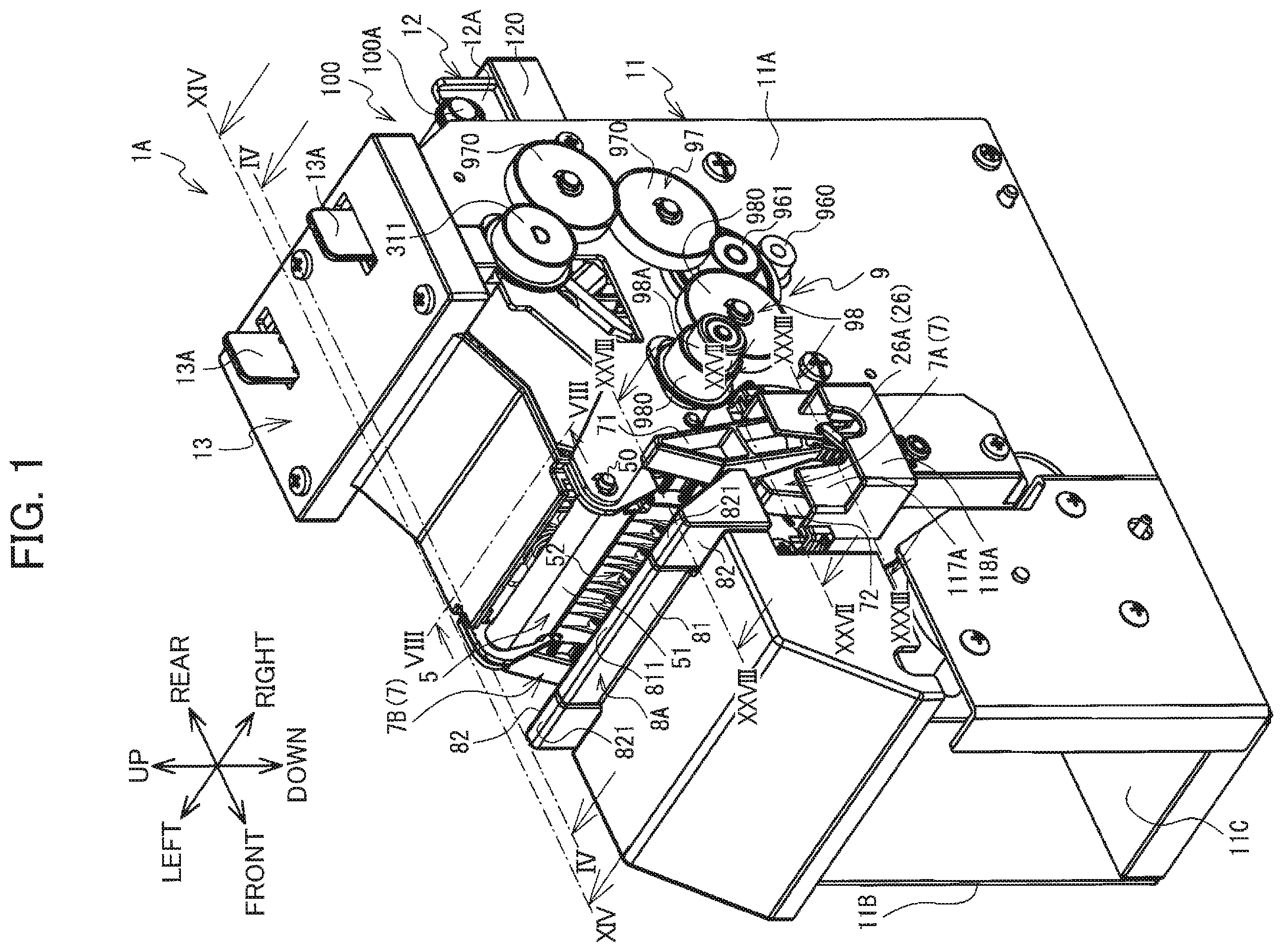
is a perspective view of a label wrapping device 1 A (cover part 13 : closed position);
is a plan view of the label wrapping device 1 A (cover part 13 : closed position);
is a right side view of the label wrapping device 1 A (cover part 13 : closed position);
is a perspective view including a cross section of the label wrapping device 1 A taken along a line IV-IV in ;
is a cross-sectional view of the label wrapping device 1 A taken along a line V-V in as viewed in a direction indicated by corresponding arrows;
is an enlarged view of an area indicated in ;
is an enlarged view of an area encircled in ;
is a perspective view of the label wrapping device 1 A (cover part 13 : open position);
is a plan view of the label wrapping device 1 A (cover part 13 : open position);
is an enlarged view of a region near a straightening member 4 in ;
is an enlarged perspective view of an upper-rear end portion of the label wrapping device 1 A;
is an enlarged view of a part illustrated in ;
is a cross-sectional view of a section taken along a line XIII-XIII in as viewed in a direction indicated by corresponding arrows;
is a cross-sectional view of a section along a line XIV-XIV in as viewed in a direction indicated by corresponding arrows;
is a perspective view of an area near an opening/closing member 5 (first position) and a guide member 8 A;
is an enlarged view of a part of the area illustrated in ;
is a perspective view of an area near the opening/closing member 5 (second position) and the guide member 8 A;
is a cross-sectional view of an area in the vicinity of the opening/closing member 5 (first position), the guide member 8 A, and a restriction part 8 B;
is a cross-sectional view of an area in the vicinity of the opening/closing member 5 (second position), the guide member 8 A, and the restriction part 8 B;
is a cross-sectional view of a section near a wrapping mechanism 6 taken along the line IV-IV in as viewed in the direction of the corresponding arrows;
shows perspective views of the area near the wrapping mechanism 6 that includes the cross section of the label wrapping device 1 A taken along the line IV-IV in ;
is an enlarged view of a part of the section illustrated in ;
is a cross-sectional view of an area near the opening/closing member 5 (second position), guide member 8 A, restriction part 8 B, and wrapping mechanism 6 ;
is an enlarged view of a first arm member 66 and a second arm member 67 depicted in (with a cable 19 A interposed therebetween);
is another enlarged view of the first arm member 66 and second arm member 67 depicted in (with a cable 19 B interposed therebetween);
is a right-side view of a retaining member 7 ;
is a cross-sectional view of a section taken along a line XXVII-XXVII in as viewed in a direction indicated by corresponding arrows;
is a cross-sectional view of a section taken along a line XXVIII-XXVIII in as viewed in a direction indicated by corresponding arrows;
illustrates a state where the cable 19 A is held by a first pinching member 71 and a second pinching member 72 in the cross-sectional view of ;
illustrates a state where the cable 19 B is held by the first pinching member 71 and second pinching member 72 in the cross-sectional view of ;
is an explanatory diagram for illustrating operations of the first pinching member 71 and the opening/closing member 5 (first position) when extracting a cable 19 from an insertion recess 62 A;
is an explanatory diagram for illustrating operations of the first pinching member 71 and the opening/closing member 5 (second position) when extracting the cable 19 from the insertion recess 62 A;
is a cross-sectional view of a section taken along a line XXXIII-XXXIII in as viewed in a direction indicated by corresponding arrows;
is a block diagram illustrating an electrical configuration of the label wrapping device 1 A;
is a flowchart illustrating steps in a main process;
is a continuation of the flowchart in ;
A through 37 F are explanatory diagrams illustrating how a label 10 A is wrapped around the cable 19 ;
is a perspective view of a label wrapping device 1 B;
is an enlarged view of a region near a straightening member 4 C in ;
is a cross-sectional view of the label wrapping device 1 B;
is a cross-sectional view of a straightening member 400 in the label wrapping device 1 B;
is a cross-sectional view of a label wrapping device 1 C; and
is a cross-sectional view of a label wrapping device 1 D.
DETAILED DESCRIPTION
A label wrapping device 1 A according to an embodiment of the present disclosure will be described while referring to the accompanying drawings. The referenced drawings are used to describe the technical features made possible with the present disclosure. The configurations and the like of apparatuses included therein are merely examples, and the present disclosure is not intended to be limited to these configurations and the like.
The label wrapping device 1 A is configured to affix a label 10 A having an adhesive surface to a cable 19 by wrapping the label 10 A around the cable 19 . In the following description, the lower-left, upper-right, upper-left, lower-right, top, and bottom of the label wrapping device 1 A in will be respectively defined as the front, rear, left, right, top, and bottom of the label wrapping device 1 A.
<Overview of the Label Wrapping Device 1 A>
An overview of the label wrapping device 1 A will be described with reference to through 9 .
The label wrapping device 1 A includes a plate-shaped frame 11 . The frame 11 includes side plates 11 A and 11 B, and a bottom plate 11 C. The side plates 11 A and 11 B are both orthogonal to a left-right direction and oppose each other to be spaced apart from each other in the left-right direction. The bottom plate 11 C extends horizontally, spanning between bottom edges of the respective side plates 11 A and 11 B. The label wrapping device 1 A is used with the bottom plate 11 C resting on a table or the like.
The frame 11 supports a conveyance base 120 . The conveyance base 120 has a thick plate shape and is sandwiched between the side plates 11 A and 11 B of the frame 11 above a vertical center thereof (see ). The conveyance base 120 extends horizontally. As illustrated in , aa front end of the conveyance base 120 is located in approximate front-rear centers of the respective side plates 11 A and 11 B. A rear end of the conveyance base 120 protrudes rearward from rear edges of the respective side plates 11 A and 11 B. As illustrated in , the conveyance base 120 has a top surface that is interrupted in a front-rear direction by a space in which a follow roller 35 described later is supported. Hereinafter, a front region of the top surface of the conveyance base 120 (on the front side of the follow roller 35 ) will be referred to as a conveying surface 120 A, and a rear region of the top surface of the conveyance base 120 (on the rear side of the follow roller 35 ) will be referred to as a conveying surface 120 B. The conveying surface 120 A is positioned lower than the conveying surface 120 B.
A holder 12 is provided on the conveying surface 120 B at a rear end portion thereof. As illustrated in , the holder 12 includes a pair of bearings 12 A that are spaced apart from each other in the left-right direction. As illustrated in through 3 , the bearings 12 A rotatably support a roll 100 configured by a label tape 10 wound around a core 100 A. The bearings 12 A rotatably support respective ends of the core 100 A. The label tape 10 includes a plurality of labels 10 A, and a release paper 10 B. The release paper 10 B is along strip to which the labels 10 A are affixed. The labels 10 A are arranged sequentially in a longitudinal direction of the release paper 10 B. Slits are pre-cut at each boundary between neighboring two labels 10 A in the longitudinal direction of the release paper 10 B.
The label tape 10 is inserted into the label wrapping device 1 A through an insertion port 2 A (see ), which is an opening provided above the conveying surface 120 B. Inside the label wrapping device 1 A, the labels 10 A are peeled off the release paper 10 B one at a time. Each label 10 A separated from the release paper 10 B is wrapped around and affixed to a cable 19 by the label wrapping device 1 A. The release paper 10 B is subsequently discharged from the label wrapping device 1 A through a discharge port 2 B (see ), which is an opening provided above the insertion port 2 A.
As illustrated in through 3 , a cover part 13 is provided on the top of the frame 11 . The cover part 13 is pivotably supported by the side plates 11 A and 11 B through a rotating shaft 50 extending in the left-right direction (see ). The rotating abaft 50 extends between top end portions of the side plates 11 A and 11 B at positions approximately front-rear centers of the respective side plates 11 A and 11 B. The cover part 13 pivots about an axis 50 C (see ) which is a centerline of the rotating shaft 50 that extends in the left-right direction. By pivoting, the cover part 13 can be switched between an orientation extending rearward from the rotating shaft 50 (see through 5 ; hereinafter called a closed position) and an orientation extending forward from the rotating shaft 50 (see ; hereinafter called an open position). As illustrated in , the conveying surface 120 A of the conveyance base 120 is exposed when the cover part 13 is disposed in the open position.
As illustrated in through 3 , the cover part 13 includes a pair of levers 13 A in positions corresponding to a top surface of the cover part 13 in the closed position. The cover part 13 also includes a pair of hooks 13 B (see ) at positions corresponding to a bottom surface of the cover part 13 in the closed position. A pair of engagement holes 13 C (see ) are formed in the top end portions of the respective side plates 11 A and 11 B near rear ends thereof. When the cover part 13 is in the closed position, the hooks 13 B engage with the corresponding engagement holes 13 C from inner sides thereof. This engagement restricts the cover part 13 from pivoting from its closed state to its open state. However, when an operation is performed to move the levers 13 A inward, the hooks 13 B also move inward. At this time, the engaged state of the hooks 13 B to the engagement holes 13 C is released. Therefore, the cover part 13 can be pivoted about the rotating shaft 50 and moved from the closed position to the open position.
The label wrapping device 1 A is used while the cover part 13 is in the closed position. As illustrated in , a surface of the cover part 13 that opposes the conveying surface 120 A of the conveyance base 120 from above when the cover part 13 is in the closed position will be called a conveying surface 130 A. When the cover part 13 is in the closed position, the conveying surface 130 A is above and slightly separated from the conveying surface 120 A. Unless specifically indicated otherwise, the directions, positional relationships, and the like of the various mechanisms will be described below under an assumption that the cover part 13 is disposed in the closed position.
As illustrated in through 5 , the frame 11 holds a guide member 2 , a conveying mechanism 3 , a straightening member 4 , an opening/closing member 5 , a wrapping mechanism 6 , retaining members 7 , a guide member 8 A, a restriction part 8 B, a drive unit 9 , and the like.
The conveying mechanism 3 is configured to draw out the label tape 10 from the roll 100 and peel the labels 10 A off the release paper 10 B while conveying the labels 10 A forward. The guide member 2 is configured to guide the label tape 10 , which is drawn off the roll 100 by the conveying mechanism 3 , and the release paper 10 B from which the labels 10 A have been separated. The straightening member 4 is configured to correct curl in the labels 10 A separated from the release paper 10 B. The wrapping mechanism 6 is configured to wrap each label 10 A around the cable 19 and affixes the label 10 A to the cable 19 . The retaining members 7 hold the cable 19 relative to the wrapping mechanism 6 in order that the wrapping mechanism 6 can wrap the label 10 A about the cable 19 and affix the label 10 A thereto. The opening/closing member 5 and guide member 8 A are configured to guide the cable 19 to the wrapping mechanism 6 . The restriction part 8 B is configured to restrict the movement of the label 10 A separated from the release paper 10 B. The drive unit 9 is configured to drive the conveying mechanism 3 , the wrapping mechanism 6 , and the like.
<Drive Unit 9 >
A motor 96 A (see ) is provided on the left side (inside) of the side plate 11 A configuring the frame 11 . As illustrated in , the motor 96 A has a rotational shaft protruding rightward from the side plate 11 A, and a gear 960 is provided on the rotational shaft. The gear 960 engages with an intermediate gear 961 , and the intermediate gear 961 is coupled with transmission parts 97 and 98 described next.
The transmission part 97 includes a plurality of gears 970 that are rotatably supported on the right surface of the side plate 11 A. The gears 970 are in mesh with each other. The transmission part 97 is interposed between the intermediate gear 961 and a stripping roller 31 of the conveying mechanism 3 described later (see ) for transmitting a rotational drive force of the motor 96 A to the stripping roller 31 . The transmission part 98 includes a plurality of gears 980 that are rotatably supported on the right surface of the side plate 11 A, and a one-way clutch 98 A. The transmission part 98 is interposed between the intermediate gear 961 and conveying rollers 32 of the conveying mechanism 3 described later (see ) for transmitting the rotational drive force of the motor 96 A to the conveying rollers 32 .
A motor 96 B (see ) is provided near front edges of the side plates 11 A and 11 B configuring the frame 11 . A rotational drive force of the motor 96 B is transmitted to the wrapping mechanism 6 described later (see ). The wrapping mechanism 6 is configured to rotate when receiving the rotational drive force of the motor 96 B. Hereinafter, the motors 96 A and 96 B will be collectively referred to as the drive unit 9 , wherever appropriate.
<Conveying Mechanism 3 >
The conveying mechanism 3 is arranged in front of the roll 100 supported by the holder 12 . As illustrated in , the conveying mechanism 3 includes the stripping roller 31 , conveying rollers 32 , follow rollers 33 - 36 , and a stripping plate 37 .
As illustrated in , the stripping roller 31 has a columnar shape. The stripping roller 31 is rotatably supported between the side plates 11 A and 11 B of the frame 11 (see ). As illustrated in , the stripping roller 31 defines an axis 31 C aligned in the left-right direction that serves as a rotational center of the stripping roller 31 . The stripping roller 31 is positioned above and is separated from the conveying surface 120 B of the conveyance base 120 . The stripping roller 31 has a length in the left-right direction that is slightly smaller than a gap between the side plates 11 A and 11 B. The stripping roller 31 includes a rotational shaft that is coupled with a gear 311 illustrated in . The gear 311 is engaged with one of the gears 970 in the transmission part 97 . The stripping roller 31 is thus configured to receive the rotational drive force of the motor 96 A transmitted by the transmission part 97 via the gear 311 . In such cases, as illustrated in , the stripping roller 31 rotates clockwise when the label wrapping device 1 A is viewed from its right side (i.e., in a direction indicated by an arrow Y 31 in ). Unless specifically indicated otherwise, the directions of rotation (clockwise or counterclockwise) in the following description will be defined based on an assumption that the label wrapping device 1 A is viewed from its right side.
As illustrated in , the follow roller 33 has a columnar shape. The follow roller 33 has a diameter and a length in the left-right direction that are both substantially the same as a diameter and a length in the left-right direction of the stripping roller 31 . The follow roller 33 is rotatably supported in the cover part 13 . As illustrated in , the follow roller 33 defines an axis 33 C aligned in the left-right direction that serves as a rotational center of the follow roller 33 . The follow roller 33 is positioned above and adjacent to the stripping roller 31 . The axis 31 C of the stripping roller 31 and the axis 33 C of the follow roller 33 extend parallel to each other and have the same position in the front-rear direction.
Springs 33 B are disposed above the follow roller 33 . The springs 33 B are interposed between the top inner surface of the cover part 13 and the follow roller 33 and exert a downward urging force on the follow roller 33 . When receiving this urging force of the springs 33 B, the follow roller 33 is moved downward and pressed against the stripping roller 31 .
As illustrated in , the conveying rollers 32 are provided near the front end of the conveyance base 120 . As illustrated in , the conveying rollers 32 include conveying rollers 32 A, 32 B, and 32 C. The conveying rollers 32 A, 32 B, and 32 C are each columnar in shape and are evenly spaced in the left-right direction. The conveying rollers 32 A, 32 B, and 32 C are coupled to a rotational shaft 320 illustrated in . The rotational shaft 320 has a columnar shape and extends in the left-right direction. The rotational shaft 320 is rotatably supported between the side plates 11 A and 11 B of the frame 11 (see ). As illustrated in , the rotational shaft 320 defines an axis 320 C extending in the left-right direction and serving as a rotational center of the rotational shaft 320 at a position below the conveying surface 120 A of the conveyance base 120 . As illustrated in , upper ends of the respective conveying rollers 32 protrude slightly above the conveying surface 120 A.
The rotational shaft 320 of the conveying rollers 32 is coupled to the one-way clutch 98 A of the transmission part 98 illustrated in . The one-way clutch 98 A is configured to transmit the rotational drive force of the motor 96 A to the conveying rollers 32 . The conveying rollers 32 is configured to receive the rotational drive force of the motor % A transmitted by the transmission part 98 via the one-way clutch 98 A. In such cases, as illustrated in , the conveying rollers 32 rotate counterclockwise (in a direction of an arrow Y 32 in ).
Note that the one-way clutch 98 A is configured to uncouple the motor 96 A from the conveying rollers 32 when the conveying rollers 32 rotate in the direction of the arrow Y 32 while the motor 96 A is halted. Accordingly, the conveying rollers 32 can freely rotate in the direction of the arrow Y 32 while the motor 96 A is halted without being affected by the torque of the motor 96 A.
As illustrated in , the follow rollers 34 include follow rollers 34 A, 34 B, and 34 C arranged in the left-right direction. The follow rollers 34 A, 34 B, and 34 C are disc-shaped with uneven circumferential edges. The follow rollers 34 are rotatably supported in the cover part 13 . As illustrated in , bottom ends of the follow rollers 34 protrude slightly downward from the conveying surface 130 A of the cover part 13 . The follow rollers 34 are positioned above and adjacent to the conveying rollers 32 . The bottom ends of the follow rollers 34 contact the upper ends of the conveying rollers 32 . More specifically, the follow roller 34 A illustrated in is above and adjacent to the conveying roller 32 A, with the bottom and of the follow roller 34 A contacting the upper end of the conveying roller 32 A. The follow roller 34 B is above and adjacent to the conveying roller 32 B, with the bottom end of the follow roller 34 B contacting the upper end of the conveying roller 32 B. The follow roller 34 C is above and adjacent to the conveying roller 32 C, with the bottom end of the follow roller 34 C contacting the upper end of the conveying roller 32 C.
As illustrated in , the follow rollers 34 define an axis 340 C that extends in the left-right direction and that serves as a rotational center of the follow rollers 34 . The axis 320 C of the conveying rollers 32 and the axis 340 C of the follow rollers 34 extend parallel to each other at the same position in the front-rear direction.
As illustrated in , the stripping plate 37 is disposed diagonally below and forward of the stripping roller 31 and rearward of the conveying rollers 32 . The stripping plate 37 has a plate shape and is sloped relative to the horizontal direction. More specifically, the stripping plate 37 slopes diagonally downward from a rear end toward a front end thereof. As illustrated in , the stripping plate 37 has a front end portion 37 A whose thickness tapers gradually toward the front end. The front end portion 37 A has a curved surface that appears substantially arc-shaped in a side view. As illustrated in , the position of the front end of the stripping plate 37 will be called a peeling point 370 . The peeling point 370 is slightly above and separated from the conveying surface 120 A of the conveyance base 120 .
As illustrated in , the follow roller 35 has a columnar shape. The follow roller 35 has a length in the left-right direction that is approximately the same as a length of the stripping plate 37 in the left-right direction. The follow roller 35 is rotatably supported in the space between the conveying surface 120 A and conveying surface 120 B of the conveyance base 120 . As illustrated in , the follow roller 35 defines an axis 35 C that extends in the left-right direction and that serves as a rotational center of the follow roller 35 . The upper end of the follow roller 35 protrudes slightly above the conveying surface 120 B. The follow roller 35 is below and adjacent to the stripping plate 37 . The follow roller 35 contacts the bottom surface of the stripping plate 37 at a position slightly forward of the top of the follow roller 35 .
As illustrated in , the follow rollers 36 include follow rollers 36 A, 36 B, 36 C, and 36 D arranged in the left-right direction. The follow rollers 36 A, 36 B, 36 C, and 36 D are disc-shaped with uneven circumferential edges. The follow rollers 36 are rotatably supported in the cover part 13 . As illustrated in , the bottom ends of the follow rollers 36 protrude slightly downward from the conveying surface 130 A of the cover part 13 . The follow rollers 36 are positioned rearward of the conveying rollers 32 and follow rollers 34 and forward of the stripping plate 37 , stripping roller 31 , and follow rollers 33 and 35 .
As illustrated in , the label tape 10 drawn off the roll 100 is inserted into the label wrapping device 1 A through the insertion port 2 A. The label tape 10 is conveyed forward along the conveying surface 120 B of the conveyance base 120 . At this time, the labels 10 A of the label tape 10 are arranged on the bottom surface of the release paper 10 B such that the top surfaces of the labels 10 A correspond to adhesive surfaces adhered to the release paper 10 B.
The label tape 10 extends forward from the bottom of the roll 100 and passes over the follow roller 35 . Subsequently, the label tape 10 bends diagonally downward and extends farther forward, passing through the gap between the follow roller 35 and the stripping plate 37 . The label tape 10 continues to extend diagonally downward along the bottom surface of the stripping plate 37 to the peeling point 370 . At this point, the release paper 10 B is bent upward around the peeling point 370 , causing the labels 10 A of the label tape 10 to separate from the release paper 10 B.
The labels 10 A peeled off by the stripping plate 37 extend forward along the conveying surface 120 A of the conveyance base 120 , passing beneath the follow rollers 36 and through the gap between the conveying rollers 32 and follow rollers 34 . At this time, the adhesive surfaces of the labels 10 A face upward. The labels 10 A are subsequently wrapped around and affixed to cables 19 by the wrapping mechanism 6 described later, which is provided on the front side of the conveyance base 120 .
In the meantime, the release paper 10 B from which the stripping plate 37 has separated the labels 10 A is bent around the peeling point 370 and extends diagonally upward and rearward along the top surface of the stripping plate 37 . The release paper 10 B continues to extend diagonally upward and rearward to the stripping roller 31 , curves rearward while in contact with the stripping roller 31 , and passes rearward through the gap between the stripping roller 31 and follow roller 33 . The release paper 10 B is then discharged from the label wrapping device 1 A through the discharge port 2 B.
Hereinafter, the area through which the label tape 10 passes when conveyed from the insertion port 2 A toward the peeling point 370 of the stripping plate 37 will be called a first conveying path R 1 . The area through which the release paper 10 B passes when conveyed from the peeling point 370 of the stripping plate 37 toward the discharge port 2 B will be called a second conveying path R 2 . The area through which the labels 10 A pass while conveyed forward from the peeling point 370 of the stripping plate 37 will be called a third conveying path R 3 .
As illustrated in , the direction along the first conveying path R 1 from the peeling point 370 of the stripping plate 37 and opposite a conveying direction of the label tape 10 is defined as a first direction D 1 . The direction along the third conveying path R 3 from the peeling point 370 and the same as the conveying direction of the label 10 A is defined as a second direction D 2 . In , assume that the first direction D 1 and the second direction D 2 define an angle θ therebetween. In this example, the angle θ is within a range of 120-155°, and more preferably the angle θ be 120°.
As illustrated in , the label wrapping device 1 A rotates the stripping roller 31 and conveying rollers 32 through the drive of the motor 96 A (see ). The stripping roller 31 rotates in the direction indicated by the arrow Y 31 to convey the release paper 10 B pinched between the stripping roller 31 and the follow roller 33 in a direction indicated by an arrow Y 11 . This action draws more of the label tape 10 off the roll 100 in a direction indicated by an arrow Y 12 .
The label tape 10 is guided along the stripping plate 37 while the follow roller 35 rotates in response to the movement of the label tape 10 . The labels 10 A are peeled off the release paper 101 B as the release paper 10 B bends around the peeling point 370 of the stripping plate 37 . The separated labels 10 A are pushed in a direction of an arrow Y 13 . The labels 10 A are guided forward by the follow rollers 36 and enters between the conveying rollers 32 and follow rollers 34 from a rear side thereof. The conveying rollers 32 rotate in a direction indicated by an arrow Y 32 and convey the labels 10 A pinched between the conveying rollers 32 and follow rollers 34 forward. The labels 10 A conveyed by the conveying rollers 32 move in a direction indicated by an arrow Y 14 to a position above the wrapping mechanism 6 , which is disposed forward of the conveyance base 120 .
Hereinafter, the direction in which the label 10 A is conveyed by the rotation of the conveying rollers 32 (the direction indicated by the arrow Y 14 ) will simply be called the conveying direction. The conveying direction is coincident with the forward direction. The upstream side in the conveying direction corresponds to the rear side of the label wrapping device 1 A. The downstream side in the conveying direction corresponds to the front side of the label wrapping device 1 A. Hereinafter, the downstream side in the conveying direction will simply be called the downstream side, and the upstream side in the conveying direction will simply be called the upstream side. As illustrated in , a plane passing through the peeling point 370 of the stripping plate 37 and the tops of the conveying rollers 32 (i.e., the surfaces of the conveying rollers 32 closest to the third conveying path R 3 ) will be defined as a datum plane M 1 .
<Guide Member 2 >
As illustrated in , the guide member 2 is detachably mounted on the conveying surface 120 B of the conveyance base 120 in front of the holder 12 . The guide member 2 includes a pair of blocks 21 , and a bridging part 22 . The blocks 21 are spaced apart from each other in the left-right direction. Respective bottom ends of the blocks 21 contact the conveying surface 120 B of the conveyance base 120 from above. The bridging part 22 spans between the pair of blocks 21 . Each of the blocks 21 has a projecting part 21 A that protrudes outward from respective outer left and right surfaces thereof. The projecting parts 21 A are positioned at front-rear centers of the respective blocks 21 to extend vertically from respective top edges to bottom edges thereof.
Side walls of the respective blocks 21 facing each other will be called a pair of side walls 23 . A portion of each side wall 23 positioned below the bridging part 22 is a first portion. The first conveying path R 1 along which the label tape 10 is conveyed when paid out from the roll 100 (see ) is located inside the first portions of the side walls 23 . Hereinafter, the first portions will be called a pair of side wall portions 23 A. The side wall portions 23 A guide the label tape 10 along the first conveying path R 1 by contacting and positioning both left and right edges of the release paper 10 B in the label tape 10 being conveyed along the first conveying path R 1 . The opening enclosed by the bridging part 22 and the pair of side wall portions 23 A corresponds to the insertion port 2 A through which the label tape 10 is inserted into the label wrapping device 1 A.
A portion of each side wall 23 positioned above the bridging part 22 constitute a second portion. The second conveying path R 2 along which the release paper 10 B is conveyed after the labels 10 A have been peeled off the release paper 10 B (see ) is located inside the second portions of the side walls 23 . Hereinafter, the second portions will be called a pair of side wall portions 23 B. The side wall portions 23 B guide the release paper 10 B along the second conveying path R 2 by contacting and positioning both left and right edges of the release paper 10 B being conveyed along the second conveying path R 2 . The opening enclosed by the bridging part 22 and the pair of side wall portions 23 B corresponds to the discharge port 2 B through which the release paper 10 B is discharged from the label wrapping device 1 A.
A pair of mounting parts 24 is provided inside the respective side plates 11 A and 11 B of the frame 11 and above the conveying surface 120 B of the conveyance base 120 . The mounting parts 24 protrude inward from the inner surfaces of the respective side plates 11 A and 11 B. A groove 24 A is formed in a front-rear center of each mounting part 24 . The grooves 24 A extend vertically between the top edge and bottom edge of the corresponding mounting parts 24 . The guide member 2 can be mounted in the label wrapping device 1 A by inserting the projecting parts 21 A into the grooves 24 A of the corresponding mounting parts 24 and can be removed from the label wrapping device 1 A by retracting the projecting parts 21 A from the corresponding grooves 24 A.
A plurality of guide members 2 having different distances between side walls 23 is prepared in advance. Specifically, since there is a plurality of types of rolls 100 having release papers 10 B of different widths, the different types of guide members 2 are configured with distances between the side walls 23 that correspond to the different widths of the release papers 10 B. With this label wrapping device 1 A, the guide member 2 to be mounted in the pair of mounting parts 24 is selected from among the plurality of guide members 2 and interchanged in conformance with the width of the release paper 10 B in the roll 100 to be mounted in the holder 12 . In this way, the distance between the pair of side walls 23 in the guide member 2 can be adjusted in the label wrapping device 1 A to conform with the width of the release paper 10 B.
<Straightening Member 4 >
As illustrated in , the straightening member 4 is provided downstream relative to the conveying rollers 32 and follow rollers 34 of the conveying mechanism 3 . As illustrated in , the straightening member 4 includes rotating bodies 4 A and ribs 4 B. The rotating bodies 4 A are arranged above the third conveying path R 3 , and the ribs 4 B are arranged below the third conveying path R 3 .
As illustrated in , the rotating bodies 4 A include rotating bodies 41 A, 41 B, 41 C, 41 D, 41 E, and 41 F arranged in the left-right direction. The rotating bodies 41 A- 41 F are disc-shaped and have uneven circumferential edges. Holes are formed through centers of the respective rotating bodies 4 A, and a rotational shaft 410 illustrated in is inserted into these holes. The rotational shaft 410 is rod-shaped and extends in the left-right direction. The rotating bodies 4 A are rotatably supported in the cover part 13 by the rotational shaft 410 . As illustrated in , the rotational shaft 410 defines an axis 410 C extending in the left-right direction and serving as a center of the rotational shaft 410 . The rotational shaft 410 is arranged so that the axis 410 C is above the conveying surface 130 A of the cover part 13 . The bottoms of the rotating bodies 4 A protrude slightly below the conveying surface 130 A.
As illustrated in , the rotating bodies 41 A- 41 F form rotating sets 411 , 412 , and 413 , each of which is configured of two rotating bodies 4 A positioned at equal distances from the left-right center of the conveying surface 130 A. Specifically, the rotating bodies 41 A and 41 F that form the rotating set 411 are separated by a separation distance L 1 in the left-right direction. The rotating bodies 41 B and 41 E that form the rotating set 412 are separated by a separation distance L 2 in the left-right direction. The rotating bodies 41 C and 41 D that form the rotating set 413 are separated by a separation distance L 3 in the left-right direction. The separation distances L 1 -L 3 are mutually different. Each of the separation distances L 1 -L 3 corresponds to the length in the left-right direction of the labels 10 A that can be used in the label wrapping device 1 A (hereinafter called the width of the labels 10 A) when the labels 10 A are conveyed along the third conveying path R 3 . That is, the separation distances L 1 -L 3 are respectively set to the different types of labels 10 A that can be used in the label wrapping device 1 A.
As illustrated in , the rotating bodies 41 B and 41 C are arranged so that both of their left-right center positions X 1 and X 2 fall between the conveying rollers 32 A and 32 B in the left-right direction. The rotating bodies 41 D and 41 E are arranged so that their respective left-right center positions X 3 and X 4 fall between the conveying rollers 32 B and 32 C in the left-right direction. Accordingly, the center positions X 1 and X 4 of the respective rotating bodies 41 B and 41 E included in the rotating set 412 and center positions X 2 and X 3 of the respective rotating bodies 41 C and 41 D included in the rotating set 413 are all arranged at different positions in the left-right direction from the conveying rollers 32 A- 32 C.
As illustrated in , the ribs 4 B include ribs 42 A, 42 B, and 42 C arranged in the left-right direction. The ribs 42 A- 42 C all protrude upward from the conveying surface 120 A. As illustrated in , the ribs 42 A, 42 B, and 42 C extend parallel to each other in the conveying direction. As illustrated in , rear ends of the respective ribs 4 B and front ends of the respective conveying rollers 32 are arranged at the same position P 42 in the front-rear direction. In other words, the rear ends of the ribs 4 B are arranged at the same position as the front ends of the conveying rollers 32 in the conveying direction. The front ends of the ribs 42 A, 42 B, and 42 C extend to the front edge of the conveying surface 120 A.
As illustrated in , the tops of the ribs 4 B are positioned slightly higher than the bottoms of the rotating bodies 4 A. That is, the distal ends of the rotating bodies 4 A and the ribs 4 B overlap each other vertically. As illustrated in , the positions of the rotating bodies 4 A and the ribs 4 B in the front-rear direction are partially the same. Accordingly, the rotating bodies 4 A and the ribs 4 B overlap each other in the left-right direction.
The label 10 A peeled off the release paper 10 B by the stripping plate 37 of the conveying mechanism 3 is conveyed along the third conveying path R 3 by the conveying rollers 32 and guided to the straightening member 4 located downstream of the conveying rollers 32 . As the label 10 A passes between the rotating bodies 4 A and the ribs 4 B of the straightening member 4 , the top adhesive surface of the label 10 A contacts the rotating bodies 4 A while the bottom surface of the label 10 A contacts the ribs 4 B. The rotating bodies 4 A and the ribs 4 B convey the label 10 A while deforming the label 10 A into a wavy shape having a series of alternating crest-like and trough-like curved parts in the left-right direction. While the label 10 A has a curling tendency due to being maintained in a rolled state in the roll 100 , the straightening member 4 can correct the curvature by deforming the label 10 A into a wavy shape.
As illustrated in , a plane extending horizontally that passes through the tops of the ribs 4 B will be defined as a datum plane M 2 . The datum plane M 2 is coincident with the datum plane M 1 (see ), which is a plane passing through the peeling point 370 of the stripping plate 37 and the tops of the conveying rollers 32 . Hereinafter, the datum planes M 1 and M 2 will be collectively referred to as a datum plane M. The bottoms of the rotating bodies 4 A are arranged lower than the datum plane M 2 , meaning that the bottoms of the rotating bodies 4 A are positioned lower than the tops of the conveying rollers 32 .
Note that while portions of the third conveying path R 3 substantially correspond to the datum plane M, strictly speaking the two are different. This is because the datum plane M is a plane while the third conveying path R 3 is defined as a region through which the label 10 A passes and transforms into a wavy shape in an area where the straightening member 4 is located. Further, since conveyance of the label 10 A is restricted by the restriction part 8 B as will be described later, the downstream end of the third conveying path R 3 corresponds to the position of the restriction part 8 B. However, the datum plane M extends further forward relative to the restriction part 8 B.
<Label Detection Sensor 46 >
As illustrated in , recesses 16 (specifically, recesses 16 A, 16 B, 16 C, 16 D, 16 B, and 16 F) are formed in the conveying surface 120 A. These recesses 16 A, 16 B, 16 C, 16 D, 16 E, and 16 F are provided in positions opposing the respective rotating bodies 41 A- 41 F when the cover part 13 is in the closed position. The recesses 16 A- 16 F are recessed slightly downward from the conveying surface 120 A to form a prescribed gap between themselves and the rotating bodies 41 A- 41 F. A rectangular through-hole 160 is provided at a position adjacent to and rightward of the rib 42 B.
As illustrated in , a label detection sensor 46 is provided beneath the through-hole 160 . The label detection sensor 46 is an actuator-type sensor having an actuator 46 A and a detection part 46 B. The actuator 46 A is rod-shaped and has a proximal end pivotably supported by the detection part 46 B. The actuator 46 A has a distal end configured to protrude from the through-hole 160 up to a position above the conveying surface 120 A. Specifically, the actuator 46 A can pivot between a state where the distal end is located above the tops of the ribs 4 B and a state where the distal end is located below the tops of the ribs 4 B.
The detection part 46 B is configured to detect the pivoted state of the actuator 46 A and output a signal based on the detection results to a CPU 91 A (see ). More specifically, the detection part 46 B is configured to output an OFF signal when the distal end of the actuator 46 A is disposed above the tops of the ribs 4 B and output an ON signal when the distal end of the actuator 46 A is disposed below the tops of the ribs 4 B.
The actuator 46 A can pivot from the state where the distal end is positioned above the tops of the ribs 4 B to the state where the distal end is positioned below the tops of the ribs 4 B when a downstream edge of the label 10 A advances between the rotating bodies 4 A and the ribs 4 B of the straightening member 4 along the third conveying path R 3 . Additionally, the actuator 46 A can pivot from the state where the distal end is positioned below the tops of the ribs 4 B to the state where the distal end is positioned above the tops of the ribs 4 B when an upstream edge of the label 10 A passes out from between the rotating bodies 4 A and the ribs 4 B of the straightening member 4 . Hence, the CPU 91 A can detect when both the downstream edge and the upstream edge of the label 10 A on the third conveying path R 3 is at the position of the straightening member 4 based on the output signals from the label detection sensor 46 . Note that a reflective optical sensor, for example, may be used as the label detection sensor 46 in place of an actuator-type sensor.
<Opening/Closing Member 5 >
As illustrated in , the opening/closing member 5 is arranged downstream of the straightening member 4 and above the third conveying path R 3 (see ). The opening/closing member 5 includes a base part 51 , rotating bodies 52 , and ribs 53 .
As illustrated in through 17 , the base part 51 has a cylindrical part 51 A, an extension part 51 B, and a pair of side plates 51 C. The cylindrical part 51 A is arranged around the rotating shaft 50 , which spans between the side plates 11 A and 11 B of the frame 11 , and is rotatable about the rotating shaft 50 . The extension part 51 B extends downward from the cylindrical part 51 A. The extension part 51 B has a front surface including an opening/closing surface 510 that intersects the front-rear direction. The side plates 51 C are provided on both left and right ends of the extension part 51 B and are orthogonal to the left-right direction.
The opening/closing member 5 is pivotably supported on the side plates 11 A and 11 B by the rotating shaft 50 . The base part 51 can pivot about the axis 50 C extending in the left-right direction (serving as the center of the rotating shaft 50 ) so that the bottom end of the extension part 51 B is movable in the front-rear direction. The position of the opening/closing member 5 when the bottom end of the extension part 51 B is moved forward will be called a first position, and the position of the opening/closing member 5 when the bottom end of the extension part 51 B is moved rearward will be called a second position. Note that the cover part 13 is similarly supported on the side plates 11 A and 11 B so as to be pivotable by the rotating shaft 50 . In other words, both the cover part 13 and the opening/closing member 5 are pivotable about the shared axis 50 C.
The rotating bodies 52 include rotating bodies 52 A, 52 B, 52 C, 52 D, and 52 B arranged in the left-right direction. The rotating bodies 52 A- 52 E are disc-shaped and have uneven circumferential edges. Portions of the respective rotating bodies 52 A- 52 E protrude outward from the extension part 51 B, the portion being on the bottom and front forward of the approximate front-rear center of each rotating body 52 .
Holes are formed in centers of the respective rotating bodies 52 . A rotational shaft 520 illustrated in is inserted into these holes. The rotational shaft 520 is rod-shaped and extends in the left-right direction. Both left and right ends of the rotational shaft 520 are supported by the side plates 51 C of the base part 51 . The rotating bodies 52 are rotatably supported in the base part 51 by the rotational shaft 520 .
As illustrated in , the rotational shaft 520 defines an axis 520 C extending in the left-right direction and serving as a center of the rotational shaft 520 . The rotating bodies 52 are respectively rotatable about the axis 520 C. The axis 520 C is positioned above and in proximity to the third conveying path R 3 (see ). Further, when the opening/closing member 5 is in the first position (see ), the bottoms of the rotating bodies 52 border the datum plane M from above. As illustrated in , the axis 50 C of the rotating shaft 50 in the opening/closing member 5 and the axis 520 C of the rotating bodies 52 are at substantially the same positions in the front-rear direction.
As illustrated in , the ribs 53 include ribs 53 A ( 531 A, 532 A), 53 B ( 531 B, 532 B), 53 C ( 531 C, 532 C), 53 D ( 531 D, 532 D), and 53 E ( 531 E, 532 E) arranged in the left-right direction. The ribs 53 A- 53 E are all plate-shaped and orthogonal to the left-right direction. The rib 531 A is poisoned rightward of and adjacent to the rotating body 52 A, and the rib 532 A is positioned leftward of and adjacent to the rotating body 52 A. The rib 531 B is positioned rightward of and adjacent to the rotating body 52 B, and the rib 532 B is positioned leftward of and adjacent to the rotating body 52 B. The rib 531 C is positioned rightward of and adjacent to the rotating body 52 C, and the rib 532 C is positioned leftward of and adjacent to the rotating body 52 C. The rib 531 D is positioned rightward of and adjacent to the rotating body 52 D, and the rib 532 D is positioned leftward of and adjacent to the rotating body 52 D. The rib 531 E is positioned rightward of and adjacent to the rotating body 52 E, and the rib 532 E is positioned leftward of and adjacent to the rotating body 52 E. The direction in which the ribs 53 are arranged adjacent to each other is coincident with the extending direction of the axis 50 C serving as the rotational center of the rotating bodies 52 .
The ribs 53 A- 53 E all have the same shape. A peripheral edge of each rib 53 extends from an upper end of the extension part 51 B near the cylindrical part 51 A in a direction that slopes forward relative to the opening/closing surface 510 . At a lower end, each rib 53 curves and extends rearward. As illustrated in , the ribs 53 are arranged forward of a datum plane passing through the axis 50 C of the rotating shaft 50 in the opening/closing member 5 and the axis 520 C of the rotating bodies 52 .
When the opening/closing member 5 is disposed in the first position, as illustrated in , the ribs 53 cover portions of the corresponding rotating bodies 52 from both left and right sides thereof, the portions protruding forward from the extension part 51 B. In other words, the ribs 53 protrude farther outward than the portions of the rotating bodies 52 protruding forward from the extension part 51 B, and more specifically, protrude farther outward than radial edges of the rotating bodies 52 in an area encompassing the top edges, front edges, and lower edges of the rotating bodies 52 (see ). Note that the bottom edges of the ribs 53 are positioned slightly higher than the bottom edges of the rotating bodies 52 (see ). In other words, the bottom edges of the rotating bodies 52 protrude lower than the bottom edges of the ribs 53 .
As illustrated in , urging parts 56 are provided on the rear side of the base part 51 in the opening/closing member 5 . As illustrated in , the urging parts 56 include urging parts 56 A and 56 B aligned in the left-right direction. The urging parts 56 A and 56 B are compression coil springs and are interposed between the rear surface on the base part 51 of the opening/closing member 5 and the cover part 13 . The urging parts 56 A and 56 B exert a forward urging force on the opening/closing member 5 . Through the urging parts 56 , the opening/closing member 5 is urged from the second position (see ) toward the first position (see ).
After curl in the label 10 A has been corrected by the straightening member 4 , the label 10 A is further conveyed by the conveying rollers 32 to pass under the opening/closing member 5 . At this time, the rotating bodies 52 of the opening/closing member 5 contact the label 10 A from above as the label 10 A is conveyed along the third conveying path R 3 . In this way, the opening/closing member 5 corrects curvature in the label 10 A, which has a tendency to curl upward, while moving the label 10 A along the third conveying path R 3 .
<Guide Member 8 A>
As illustrated in , the guide member 8 A is disposed downstream of the opening/closing member 5 and above the datum plane M (see ). As illustrated in , the guide member 8 A includes a first part 81 adjacent to the opening/closing member 5 on the downstream side, and a pair of second parts 82 disposed respectively on left and right sides of the first part 81 . The first part 81 has a length in the left-right direction approximately equivalent to a length of the opening/closing member 5 in the left-right direction.
As illustrated in , the first part 81 has a rear portion having a sloped surface 81 A thereon. Each of the second parts 82 has a rear portion having a sloped surface 82 A thereon. The sloped surfaces 81 A and 82 A slope downward from respective front edges toward respective rear edges thereof. The front edges of the sloped surfaces 81 A and 82 A are top edges 811 and 821 located at the highest points on the sloped surfaces 81 A and 82 A, respectively. The top edges 811 and 821 are at a lower vertical position than the rotating shaft 50 that rotatably supports the opening/closing member 5 . As illustrated in , the rear edge of the sloped surface 81 A formed on the first part 81 constitutes a bottom edge 812 . The bottom edge 812 is located at the lowest point on the sloped surface 81 A and positioned in proximity to the third conveying path R 3 .
The bottom end of the opening/closing member 5 is adjacent to the bottom edge 812 of the guide member 8 A when the opening/closing member 5 is in the first position (see ). At this time, the ribs 53 contact the bottom edge 812 of the guide member 8 A. However, when the opening/closing member 5 is in the second position (see ), the bottom end of the opening/closing member 5 is separated rearward from the bottom edge 812 of the guide member 8 A.
A cable 19 about which the label 10 A is to be wrapped is mounted into the label wrapping device 1 A from above the guide member 8 A while being extended in the left-right direction. At this time, the cable 19 is guided diagonally downward and rearward along the sloped surfaces 81 A and 82 A of the guide member 8 A, as illustrated in , and continues to be guided toward an insertion recess 62 A of the wrapping mechanism 6 described later (see ).
Note that, relative to a moving direction of the cable 19 guided by the guide member 8 A (diagonally downward and rearward), the edges of the ribs 53 facing a direction opposite the moving direction of the cable 19 (diagonally upward and forward) protrude farther outward than the radial edges of the rotating bodies 52 when the opening/closing member 5 is in the first position. Therefore, the cable 19 contacts the ribs 53 of the opening/closing member 5 while being guided by the guide member 8 A toward the insertion recess 62 A of the wrapping mechanism 6 . The cable 19 exerts an external force on the bottom end of the opening/closing member 5 from above. At this time, the bottom end of the opening/closing member 5 moves rearward against the urging force of the urging parts 56 , moving the opening/closing member 5 from the first position to the second position, as illustrated in . As a result, an opening 620 B of the wrapping mechanism 6 described later is switched from a closed state closed by the opening/closing member 5 (see ) to an open state (see ).
<Restriction Part 8 B>
As illustrated in , the restriction part 8 B is formed below the bottom edge 812 of the first part 81 of the guide member 8 A. The restriction part 8 B has a recess 85 that is recessed forward. The recess 85 extends linearly in the left-right direction. The recess 85 has restriction walls 86 , 87 , and 88 configuring inner walls of the recess 85 .
The restriction wall 86 corresponds to a bottom wall in the recess 85 and is orthogonal to the front-rear direction. The restriction wall 86 is positioned on the downstream side of the downstream end of the third conveying path R 3 and intersects the datum plane M. The restriction wall 87 is a portion constituting one of side walls of the recess 85 that extends from the top edge of the restriction wall 86 . The restriction wall 87 intersects the vertical direction and extends diagonally upward and rearward from the top edge of the restriction wall 86 toward the bottom edge 812 of the guide member 8 A. The restriction wall 87 is arranged above the third conveying path R 3 and the datum plane M. The restriction wall 88 is a portion constituting another side wall of the recess 85 that extends from the bottom edge of restriction wall 86 . The restriction wall 88 is orthogonal to the vertical direction and extends horizontally rearward from the bottom edge of the restriction wall 86 . The restriction wall 88 is arranged below the third conveying path R 3 and the datum plane M.
As illustrated in , the label 10 A conveyed by the conveying rollers 32 passes the opening/closing member 5 and is further conveyed until the downstream edge contacts the restriction part 8 B. The downstream edge of the label 10 A contacts the restriction wall 86 , whereby the restriction part 8 B restricts the label 10 A from being conveyed further downstream.
As the cable 19 is guided downward toward the wrapping mechanism 6 by the guide member 8 A, the cable 19 contacts the label 10 A from above, as illustrated in . A portion of the cable 19 adheres to the adhesive surface on the top surface of the label 10 A. In response to this downward movement of the cable 19 , the downstream edge of the label 10 A may attempt to move vertically. However, the restriction wall 87 of the restriction part 8 B restricts the downstream edge of the label 10 A from moving above the third conveying path R 3 . Further, the restriction wall 88 of the restriction part 8 B restricts the downstream edge of the label 10 A from moving below the third conveying path R 3 .
<Wrapping Mechanism 6 >
As illustrated in , the wrapping mechanism 6 includes a substantially cylindrical base part 61 whose peripheral side surfaces are partially omitted. The base part 61 is rotatably supported by the frame 11 so as to be rotatable about a prescribed axis 6 A serving as a center of the base part 61 . The axis 6 A extends in the left-right direction.
As illustrated in , the base part 61 includes a first bottom wall part 621 provided on the right end (see ), a second bottom wall part 622 provided on the left end, and side wall parts 63 A, 63 B, and 63 C. The first bottom wall part 621 and second bottom wall part 622 are both disc-shaped and are separated but oppose each other in the left-right direction. Hereinafter, the first bottom wall part 621 and second bottom wall part 622 will be collectively referred to as a bottom wall part 62 .
As illustrated in , a second insertion recess 622 A is formed in the second bottom wall part 622 . The second insertion recess 622 A is recessed toward the axis 6 A from the peripheral edge of the second bottom wall part 622 . While not illustrated in the drawing, a first insertion recess having a similar shape to the second insertion recess 622 A is formed in the first bottom wall part 621 . Hereinafter, the first insertion recess and the second insertion recess 622 A will be collectively called the insertion recess 62 A.
More specifically, the insertion recess 62 A has a general U-shape and extends in a prescribed radial direction (upward) from a position in the bottom wall part 62 a prescribed distance below the axis 6 A (hereinafter called a bottom part 620 A) to the opening 620 B corresponding to a peripheral portion of the bottom wall part 62 . Below, the direction in which the insertion recess 62 A extends will be called an extension direction S. The direction from the opening 620 B toward the bottom part 620 A that corresponds to the extension direction S will be called an insertion direction S 1 , as indicated in .
As illustrated in , the cable 19 and the label 10 A can be inserted into the insertion recess 62 A when the wrapping mechanism 6 is oriented with the opening 620 B positioned above the bottom part 620 A, i.e., with the extension direction S aligned vertically. Hereinafter, the rotated position of the wrapping mechanism 6 at which the cable 19 is insertable, i.e., the rotated position of the wrapping mechanism 6 at which the opening 620 B is disposed above the bottom part 620 A, will be called an initial position. Unless specifically indicated otherwise, the following description will assume that the wrapping mechanism 6 is disposed in the initial position. While the wrapping mechanism 6 is in the initial position, the conveying direction of the label 10 A is orthogonal to both the axis 6 A and the extension direction S.
As illustrated in , the insertion recess 62 A is disposed downstream of the conveying rollers 32 and the straightening member 4 and below the third conveying path R 3 . The insertion recess 62 A opens toward the third conveying path R 3 . The insertion recess 62 A is disposed upstream of the restriction part 8 B (the restriction walls 86 , 87 , and 88 ). As illustrated in , the insertion recess 62 A and opening 620 B vertically overlap the axis 50 C, which corresponds to the pivoting center of the opening/closing member 5 . The axis 6 A, which corresponds to the rotational center of the base part 61 , is positioned slightly rearward relative to the axis 50 C.
As illustrated in , the insertion recess 62 A and opening 620 B are closed by the opening/closing member 5 when the opening/closing member 5 is in the first position. As illustrated in , the insertion recess 62 A and opening 620 B are open and not closed by the opening/closing member 5 when the opening/closing member 5 is in the second position.
As illustrated in , the wrapping mechanism 6 includes a first arm member 66 , a second arm member 67 , first springs 681 and 682 (see ), and second springs 691 and 692 (see ) disposed inside the base part 61 . The first arm member 66 and second arm member 67 hold the cable 19 from opposite sides thereof when the wrapping mechanism 6 wraps the label 10 A around the cable 19 (see ). The first springs 681 and 682 and the second springs 691 and 692 urge the first arm member 66 and second arm member 67 in order to hold the cable 19 (see ).
As illustrated in , the first arm member 66 and the second arm member 67 have bent plate shapes that extend in the left-right direction between the first bottom wall part 621 and the second bottom wall part 622 . The first arm member 66 is disposed downstream of the second arm member 67 . The first arm member 66 and the second arm member 67 oppose each other in the front-rear direction. Hereinafter, a part of the first arm member 66 on the side opposing the second arm member 67 , i.e., a rear end part of the first arm member 66 , will be called a first opposing part 660 . A part of the second arm member 67 on the side opposing the first arm member 66 , i.e., a front end part of the second arm member 67 , will be called a second opposing part 670 .
As illustrated in , the first arm member 66 has a first proximal part 66 A, a first distal part 66 B, a first sloped part 66 C, a second sloped part 66 D, and a first protruding part 66 E.
The first proximal part 66 A is pivotably supported about a rotational shaft 661 that spans between the first bottom wall part 621 and the second bottom wall part 622 (see ). The first bottom wall part 621 and the second bottom wall part 622 support the rotational shaft 661 near the downstream side of the opening 620 B formed in the insertion recess 62 A. Accordingly, the first proximal part 66 A is also disposed near the downstream side of the opening 620 B. A distance in the extension direction S between the opening 620 B and the first proximal part 66 A is shorter than a distance in the extension direction S between the bottom part 620 A and the first proximal part 66 A. The first distal part 66 B is disposed opposite the opening 620 B with respect to the bottom part 620 A in the insertion recess 62 A in the extension direction S, i.e., below the bottom part 620 A.
The first sloped part 66 C and the second sloped part 66 D correspond to a portion of the first opposing part 660 between the first proximal part 66 A and the first distal part 66 B. Both the first sloped part 66 C and the second sloped part 66 D are sloped relative to the insertion direction 81 . This is described next in greater detail.
As illustrated in , a portion of the first sloped part 66 C is arranged on the opening 620 B side (see ) of the axis 6 A in the extension direction S. The first sloped part 66 C slopes in a direction S 11 away from the axis 6 A relative to the insertion direction S 1 . A portion of the second sloped part 66 D is disposed on the opposite side of the axis 6 A from the opening 620 B in the extension direction S. The second sloped part 66 D is adjacent to the first distal part 66 B side of the first sloped part 66 C. The second sloped part 66 D slopes in a direction S 12 toward the axis 6 A relative to the insertion direction S 1 . Hereinafter, the first sloped part 66 C and the second sloped part 66 D will be collectively called a sloped portion 662 .
As illustrated in , the second arm member 67 has a second proximal part 67 A, a second distal part 67 B, a first sloped part 67 C, a second sloped part 67 D, and a second protruding part 67 E.
The second proximal part 67 A is pivotably supported about a rotational shaft 671 that spans between the first bottom wall part 621 and the second bottom wall part 622 (see ). The first bottom wall part 621 and the second bottom wall part 622 support the rotational shaft 671 near the upstream side of the opening 620 B formed in the insertion recess 62 A. Accordingly, the second proximal part 67 A is also disposed near the upstream side of the opening 620 B. A distance in the extension direction S from the opening 620 B to the second proximal part 67 A is shorter than a distance in the extension direction S from the bottom part 620 A to the second proximal part 67 A. The second distal part 67 B is disposed opposite the opening 620 B with respect to the bottom part 620 A in the insertion recess 62 A in the extension direction S, i.e., below the bottom part 620 A. The first proximal part 66 A and the second proximal part 67 A are arranged on different sides of the insertion recess 62 A from each other in the conveying direction.
The first sloped part 67 C and the second sloped part 67 D correspond to a portion of the second opposing part 670 between the second proximal part 67 A and the second distal part 67 B. Both the first sloped part 67 C and the second sloped part 67 D slope relative to the insertion direction S 1 . This will be described next in greater detail.
As illustrated in , a portion of the first sloped part 67 C is disposed on the opening 620 B side of the axis 6 A in the extension direction S. The first sloped part 67 C slopes in a direction S 21 away from the axis 6 A relative to the insertion direction S 1 . A portion of the second sloped part 67 D is disposed on the opposite side of the axis 6 A from the opening 620 B in the extension direction S. The second sloped part 67 D is adjacent to the second distal part 67 B side of the first sloped part 67 C. The second sloped part 67 D slopes in a direction S 22 toward the axis 6 A relative to the insertion direction S 1 . Hereinafter, the first sloped part 67 C and the second sloped part 67 D will be collectively called a sloped part 672 .
The first sloped part 66 C of the first arm member 66 and the first sloped part 67 C of the second arm member 67 oppose each other in the front-rear direction across the axis 6 A. The second sloped part 66 D of the first arm member 66 and the second sloped part 67 D of the second arm member 67 oppose each other in the front-rear direction across the axis 6 A.
As illustrated in , the first springs 681 and 682 are interposed between the side wall part 63 B of the base part 61 and the first arm member 66 . The second springs 691 and 692 are interposed between the side wall part 63 C of the base part 61 and the second arm member 67 . The first springs 681 and 682 are aligned in the extending direction of the axis 6 A. The second springs 691 and 692 are also aligned in the extending direction of the axis 6 A. The first springs 681 and 682 and the second springs 691 and 692 are compression springs with identical characteristics and have the same amount of compression.
The first springs 681 and 682 urge the first arm member 66 in a direction toward the second arm member 67 . The second springs 691 and 692 urge the second arm member 67 in a direction toward the first arm member 66 . The urging force exerted by the first springs 681 and 682 on the first arm member 66 matches the urging force exerted by the second springs 691 and 692 on the second arm member 67 .
As illustrated in , a rib 630 is provided on the side wall part 63 A. The rib 630 protrudes from the side wall part 63 A in a direction opposite the insertion direction S 1 . The rib 630 extends in the left-right direction. The rib 630 has a tapered tip end portion whose thickness decreases toward the distal edge of the rib 630 . Owing to the urging force of the first springs 681 and 682 , the rear surface along the bottom edge of the first arm member 66 contacts the front surface of the tapered tip end portion of the rib 630 . Similarly, owing to the urging force of the second springs 691 and 692 , the front surface along the bottom edge of the second arm member 67 contacts the rear surface of the tapered tip end portion of the rib 630 .
As illustrated in , the first protruding part 66 E of the first arm member 66 protrudes toward the second arm member 67 . Within the first opposing part 660 of the first arm member 66 , the first protruding part 66 E is adjacent to the first sloped part 66 C on the first proximal part 66 A side. A straight line connecting an axis of the rotational shaft 661 of the first arm member 66 and a connection point between the first sloped part 66 C and the second sloped part 66 D is defined as a line T 1 . Based on this line T 1 , a protruding amount Q 1 of the first protruding part 66 E can be defined as a distance between the line T 1 and the first protruding part 66 E.
The second protruding part 67 E of the second arm member 67 protrudes toward the first arm member 66 . Within the second opposing part 670 of the second arm member 67 , the second protruding part 67 E is adjacent to the first sloped part 67 C on the second proximal part 67 A side. A straight line connecting an axis of the rotational shaft 671 of the second arm member 67 and a connection point between the first sloped part 67 C and the second sloped part 67 D is defined as a line 12 . Based on this line T 2 , a protruding amount Q 2 of the second protruding part 67 E can be defined as a distance between the line 12 and the second protruding part 67 E. In this example, the protruding amount Q 2 of the second protruding part 67 E is greater than the protruding amount Q 1 of the first protruding part 66 E.
As illustrated in , the cable 19 guided downward by the guide member 8 A enters the insertion recess 62 A through the opening 620 B. In conformance with the direction in which the cable 19 moves when guided along the sloped surfaces 81 A and 82 A of the guide member 8 A, the cable 19 enters the insertion recess 62 A while moving diagonally downward and rearward. Consequently, the cable 19 initially contacts the second protruding part 67 E of the second arm member 67 (see ), thereby moving the second arm member 67 rearward against the urging force of the second springs 691 and 692 . Through the contact with the second protruding part 67 E, the cable 19 is guided downward.
Next, the cable 19 contacts the first protruding part 66 E of the first arm member 66 (see ), moving the first arm member 66 forward against the urging force of the first springs 681 and 682 , and continues to move downward. As illustrated in , the cable 19 is gripped and held between the sloped portion 662 of the first arm member 66 and the sloped part 672 of the second arm member 67 from respective front and rear sides. Hereinafter, the position in which the cable 19 is held by the first arm member 66 and second arm member 67 will be called a wrapping position Pm. The longitudinal direction of the cable 19 disposed in the wrapping position Pm is aligned in the left-right direction and orthogonal to the insertion direction S 1 of the cable 19 .
shows an example in which a cable 19 A having a relatively small diameter has been inserted into the insertion recess 62 A. In this case, the cable 19 A is held in contact with the first sloped parts 66 C and 67 C and the second sloped parts 66 D and 67 D of the corresponding first arm member 66 and second arm member 67 . While the cable 19 A is held by the first arm member 66 and the second arm member 67 , the axis 6 A corresponding to the rotational center of the wrapping mechanism 6 is substantially aligned with a centerline C of the cable 19 A.
On the other hand, shows an example in which a cable 19 B having a relatively large diameter has been inserted into the insertion recess 62 A. In this case, the cable 19 B is gripped and held by the first sloped parts 66 C and 67 C of the corresponding first arm member 66 and second arm member 67 and the bottom part 620 A of the insertion recess 62 A. While the cable 19 B is held by the first arm member 66 , second arm member 67 , and bottom part 620 A of the insertion recess 62 A, the axis 6 A corresponding to the rotational center of the wrapping mechanism 6 is substantially aligned with the centerline C of the cable 19 B. In other words, the wrapping mechanism 6 can always hold a cable 19 so that the centerline C of the cable 19 corresponds approximately to the axis 6 A, regardless of the diameter of the cable 19 . Note that, since the label 10 A is not depicted in , a slight gap equivalent to the thickness of the label 10 A is illustrated between the cable 19 B and the bottom part 620 A.
Further, since the cable 19 is inserted into the insertion recess 62 A together with the label 10 A, the label 10 A is interposed between the first arm member 66 and second arm member 67 and the cable 19 while the cable 19 is held in the wrapping position Pm, as illustrated in . In this state, the label 10 A is wrapped around and affixed to an area on the approximate bottom half of the cable 19 , i.e., the approximate lower half of the circumferential surface of the cable 19 . In this state, the label wrapping device 1 A drives the motor 96 B (see ) to rotate the wrapping mechanism 6 . The wrapping mechanism 6 rotates on its axis 6 A around the cable 19 . At this time, the label 10 A is guided to wrap around the cable 19 disposed in the wrapping position Pm. As a result, the label 10 A is wrapped around and affixed to the cable 19 .
<Wrapping Sensor 69 >
As illustrated in , the wrapping mechanism 6 includes a protruding part 69 A that protrudes outward from the second bottom wall part 622 at an area forward of the side wall part 63 A constituting the base part 61 . A wrapping sensor 69 is provided on the side plate 11 B of the frame 11 (see ) diagonally downward and forward of the base part 61 . The wrapping sensor 69 is a contact-type position sensor capable of detecting proximity of the protruding part 69 A. The wrapping sensor 69 is configured to output an OFF signal to the CPU 91 A (see ) when the protruding part 69 A is separated from the wrapping sensor 69 and output an ON signal to the CPU 91 A when the protruding part 69 A is positioned near the wrapping sensor 69 . Therefore, by accumulating the number of times the wrapping sensor 69 outputs an ON signal, the CPU 91 A can detect the number of times the protruding part 69 A has contacted the wrapping sensor 69 to identify the number of rotations of the wrapping mechanism 6 .
Note that the wrapping mechanism 6 is in its initial position while the protruding part 69 A is adjacent to the wrapping sensor 69 . Accordingly, the CPU 91 A can determine that the wrapping mechanism 6 is in the initial position when the wrapping sensor 69 outputs an ON signal.
<Retaining Members 7 >
As illustrated in , the retaining members 7 include retaining members 7 A and 7 B. The retaining member 7 A is disposed on the right side of the wrapping mechanism 6 (see , etc.). Covers 117 A and 118 A that are coupled with the right surface of the side plate 11 A cover a lower portion of the retaining member 7 A from the right side. The retaining member 7 B is disposed on the left side of the wrapping mechanism 6 (see , etc.). Covers 117 B and 118 B coupled to the left surface of the side plate 11 B (see ) cover a lower portion of the retaining member 7 B from the left side. The structures of the retaining members 7 A and 7 B have left-right symmetry about a plane orthogonal to the left-right direction and passing through the left-right center of the label wrapping device 1 A.
The retaining members 7 A and 7 B are configured to guide the cable 19 introduced into the insertion recess 62 A of the wrapping mechanism 6 (see ) downward to the wrapping position Pm (see ) at two locations separated in the left-right direction and hold the cable 19 in the wrapping position Pm. Hereinafter, the retaining member 7 A will be described in detail, while a description of the retaining member 7 B will be omitted.
As illustrated in through 28 , the retaining member 7 A includes a first pinching member 71 , a second pinching member 72 , and an urging part 73 (see ). As illustrated in , the first pinching member 71 extends diagonally downward toward the rear from a position rearward of the right one of the second parts 82 of the guide member 8 A, bends forward midway, and further extends diagonally downward toward the front. The second pinching member 72 extends diagonally downward and rearward from a position below the right one of the second parts 82 of the guide member 8 A. The first pinching member 71 and second pinching member 72 intersect each other near their lower end portions. The first pinching member 71 and second pinching member 72 are both pivotably supported about a pivoting shaft 70 that extends in the left-right direction through this point of intersection. The pivoting shaft 70 is provided at the side plate 11 A of the frame 11 and extends rightward therefrom. The pivoting shaft 70 is positioned below and is separated from the wrapping position Pm, which is the position of the cable 19 when the wrapping mechanism 6 wraps the label 10 A around the cable 19 .
A protruding part 110 is provided on the side plate 11 A beneath the pivoting shaft 70 . The protruding part 110 protrudes rightward from the side plate 11 A. The bottom end portion of the first pinching member 71 contacts the protruding part 110 from its front side, while the bottom end portion of the second pinching member 72 contacts the protruding part 110 from its rear side. The first pinching member 71 and second pinching member 72 are maintained in positions at which their respective bottom end portions contact the protruding part 110 owing to the urging force of the urging part 73 described later.
As illustrated in , the cover 117 A covers respective lower portions of the first pinching member 71 and second pinching member 72 . The cover 117 A has a recess 119 A that is recessed downward from an upper edge of the cover 117 A. The wrapping position Pm is located in a bottom portion of the recess 119 A.
As indicated in , a part of a front end of the first pinching member 71 positioned above the pivoting shaft 70 is referred to as a first opposing part 710 , while a part of a rear end of the second pinching member 72 positioned above the pivoting shaft 70 is referred to as a second opposing part 720 . The second opposing part 720 of the second pinching member 72 is arranged forward relative to the first opposing part 710 of the first pinching member 71 . Using a gap formed between the first opposing part 710 of the first pinching member 71 and the second opposing part 720 of the second pinching member 72 , the retaining member 7 (retaining member 7 A) guides the cable 19 downward to the wrapping position Pm and holds the cable 19 in the wrapping position Pm.
As illustrated in through 28 , the first pinching member 71 has a first sloped part 711 at an upper end of the first opposing part 710 . The first sloped part 711 extends in a direction sloping relative to the vertical direction, and more specifically extends diagonally upward and rearward toward a distal end of the first pinching member 71 . The first sloped part 711 is arranged rearward of the sloped surface 82 A of the second part 82 on the right. A front-rear distance between the first sloped part 711 and the sloped surface 82 A grows larger toward the top. That is, the first sloped part 711 slopes so that the distance in the front-rear direction between the first sloped part 711 and the sloped surface 82 A increases at higher positions. Similarly, the sloped surface 82 A slopes in a direction for increasing the distance between the sloped surface 82 A and first sloped part 711 at higher positions.
The second pinching member 72 has a second sloped part 721 on an upper end of the second opposing part 720 . The second sloped part 721 extends in a direction sloping relative to the vertical direction, and more specifically diagonally upward and forward toward a distal end of the second pinching member 72 . In other words, the second sloped part 721 slopes in a direction separating away from the first pinching member 71 toward the top. Conversely, the first sloped part 711 slopes in a direction separating away from the second pinching member 72 toward the top.
The second sloped part 721 is positioned lower than the first sloped part 711 of the first pinching member 71 and higher than the wrapping position Pm. That is, a vertical distance between the first sloped part 711 and the wrapping position Pm is greater than a vertical distance between the second sloped part 721 and the wrapping position Pm.
As illustrated in , the urging part 73 is a torsion spring wound around the pivoting shaft 70 . One end 73 A of the urging part 73 is connected to the inside of the first pinching member 71 , while the other end 73 B of the urging part 73 is connected to the inside of the second pinching member 72 . The urging part 73 urges the first pinching member 71 in a counterclockwise direction and urges the second pinching member 72 in a clockwise direction. Accordingly, the urging part 73 urges the first pinching member 71 and second pinching member 72 in directions for moving the first opposing part 710 and second opposing part 720 toward each other. Through the urging force of the urging part 73 , the bottom and portions of the first pinching member 71 and second pinching member 72 are maintained in positions (hereinafter called their original positions) at which both bottom end portions are in contact with the protruding part 110 .
As illustrated in , the first pinching member 71 has a guiding portion 76 in an area above the point of intersection where the first opposing part 710 intersects the second opposing part 720 of the second pinching member 72 . The guiding portion 76 has sloped parts 76 A and 76 B and an inflection part 76 C. The sloped part 76 A extends diagonally downward and rearward, while the sloped part 76 B extends diagonally downward and forward. A bottom end of the sloped part 76 A and a top end of the sloped part 76 B are connected via the inflection part 76 C. The sloped parts 76 A and 76 B define an angle of approximately 150° therebetween at the inflection part 76 C. A plurality of recesses 761 is formed in the sloped part 76 B.
The second pinching member 72 has a guiding portion 77 in an area above a point of intersection where the second opposing part 720 intersects the first opposing part 710 of the first pinching member 71 . The guiding portion 77 has sloped parts 77 A and 77 B, and an inflection part 77 C. The sloped part 77 A extends diagonally downward and forward, while the sloped part 77 B extends diagonally downward and rearward. A bottom end of the sloped part 77 A and a top end of the sloped part 77 B are connected via the inflection part 77 C. The sloped parts 77 A and 77 B define an angle of approximately 150° therebetween at the inflection part 77 C. A plurality of recesses 771 is formed in the sloped part 77 B.
As illustrated in , a protruding part 71 D is provided on an inner surface of the first pinching member 71 , the inner surface being a surface near the opening/closing member 5 . The protruding part 71 D protrudes inward from the inner surface of the first pinching member 71 . The protruding part 71 D is positioned on the front side of a protruding part 51 D that protrudes outward from the right side plate 51 C of the opening/closing member 5 . The protruding parts 51 D and 71 D are positioned outside of the insertion recess 62 A in the wrapping mechanism 6 with respect to the left-right direction.
When a cable 19 is mounted in the label wrapping device 1 A, the cable 19 is guided diagonally downward and rearward along the sloped surface 82 A of the guide member 8 A toward the first sloped part 711 of the first pinching member 71 . The cable 19 contacts the first sloped part 711 , thereby pivoting the first pinching member 71 in the clockwise direction against the urging force of the urging part 73 . Through this contact with the first sloped part 711 , the cable 19 is guided diagonally downward and forward, entering the insertion recess 62 A of the wrapping mechanism 6 .
Subsequently, the cable 19 contacts the second sloped part 721 of the second pinching member 72 to pivot the second pinching member 72 in the counterclockwise direction against the urging force of the urging part 73 . Through this contact with the second sloped part 721 , the cable 19 is guided downward. While sandwiched from both front and rear sides by the first opposing part 710 of the first pinching member 71 and the second opposing part 720 of the second pinching member 72 , the cable 19 moves downward.
As illustrated in , the guiding portion 76 of the first pinching member 71 and the guiding portion 77 of the second pinching member 72 nip the cable 19 from front and rear sides thereof in the front-rear direction. The sloped part 76 A of the guiding portion 76 and the sloped part 77 A of the guiding portion 77 apply a downward force on the cable 19 in response to the urging force of the urging part 73 . As a result, the cable 19 is guided downward toward the wrapping position Pm.
The first pinching member 71 and the second pinching member 72 are urged to pivot in directions for returning to their original positions by the urging force of the urging part 73 until the cable 19 reaches the wrapping position Pm. Further, the sloped part 76 B of the guiding portion 76 and the sloped part 77 B of the guiding portion 77 restrict further downward movement of the cable 19 . In this way, the cable 19 is pinched from front and rear sides by the guiding portions 76 and 77 of the corresponding first pinching member 71 and second pinching member 72 and held in the wrapping position Pm.
At this time, the centerline C of the cable 19 at the wrapping position Pm is near a straight line Z connecting the inflection part 76 C of the guiding portion 76 with the inflection part 77 C of the guiding portion 77 . Therefore, the centerline C of the cable 19 is at approximately the same position when a cable 19 A having a relatively small diameter is held by the first pinching member 71 and second pinching member 72 (see ) and when a cable 19 B having a relatively large diameter is held by the first pinching member 71 and second pinching member 72 (see ). Note that the centerline C of the cable 19 held by the first pinching member 71 and the second pinching member 72 is at approximately the same position as the axis 6 A corresponding to the rotational center of the wrapping mechanism 6 (see ).
On the other hand, when the cable 19 is being removed from the label wrapping device 1 A, an upward force is exerted on the cable 19 disposed in the wrapping position Pm. As the cable 19 is withdrawn from the insertion recess 62 A of the wrapping mechanism 6 , the cable 19 contacts the sloped part 76 A of the first pinching member 71 and the sloped part 77 A of the second pinching member 72 from below. In response to the force applied by the cable 19 to the sloped part 76 A, the first pinching member 71 pivots in the clockwise direction against the urging force of the urging part 73 .
At this time, the protruding part 71 D of the first pinching member 71 comes into contact with the protruding part 51 D of the opening/closing member 5 from its front side, as illustrated in , pushing the opening/closing member 5 rearward. As illustrated in , the opening/closing member 5 thus moves from the first position toward the second position, uncovering the opening 620 B in the insertion recess 62 A. The cable 19 passes through the exposed opening 620 B and is removed upward from the insertion recess 62 A.
After the cable 19 has been removed, the first pinching member 71 is pivoted counterclockwise by the urging force of the urging part 73 and returns to its original position. At the same time, the opening/closing member 5 moves from the second position to the first position, thereby covering the opening 620 B in the insertion recess 62 A. The second pinching member 72 is also pivoted clockwise by the urging force of the urging part 73 and returns to its original position.
<Detection Parts 26 >
As illustrated in , a detection part 26 A is provided on the right side of the retaining member 7 A, and a detection part 26 B is provided on the left side of the retaining member 7 B. The detection parts 26 A and 26 B are separated from each other in the left-right direction. The detection parts 26 A and 26 B have the same construction. Below, the detection part 26 A will be described, while a description of the detection part 26 B will be omitted. The detection parts 26 A and 26 B are collectively referred to as a detection part 26 .
As illustrated in , the detection part 26 A is disposed on a right surface of the cover 117 A at a position higher than the pivoting shaft 70 for the first pinching member 71 and the second pinching member 72 . The detection part 26 A is a contact-type displacement sensor and includes a main body 27 and a movable piece 28 .
The main body 27 has a box shape and is fixed to the right surface of the cover 117 A. The cover 118 A provided on the right side of the cover 117 A (see ) covers the main body 27 from its right side. The movable piece 28 has an elongated plate shape that extends diagonally upward and rearward from the main body 27 . The movable piece 28 is arranged above the bottom portion of the recess 119 A formed in the cover 117 A. The movable piece 28 has a bottom end that is pivotably supported by the main body 27 . The main body 27 has a built-in switch that can detect downward movement of a distal end of the movable piece 28 when the movable piece 28 pivots.
When a cable 19 is inserted into the insertion recess 62 A of the wrapping mechanism 6 , the cable 19 contacts the movable pieces 28 of the corresponding detection parts 26 A and 26 B. As the cable 19 moves down into the wrapping position Pm, the movable pieces 28 are pushed by the cable 19 from above and pivot so that the distal ends of the movable piece 28 move downward. The main bodies 27 of the corresponding detection parts 26 A and 26 B detect the movement of the movable pieces 28 and output ON signals to the CPU 91 A (see ). Conversely, when the movable pieces 28 move upward, the main bodies 27 of the corresponding detection parts 26 A and 26 B output OFF signals to the CPU 91 A. Accordingly, the CPU 91 A can detect whether the cable 19 is at the wrapping position Pm in both the right retaining member 7 A and the left retaining member 7 B.
<Electrical Configuration>
Next, an electrical configuration of the label wrapping device 1 A will be described with reference to .
The label wrapping device 1 A includes the CPU 91 A, a ROM 91 B, a RAM 91 C, a flash memory 91 D, and an input/output interface 91 E, all of which are interconnected via a data bus 92 . The CPU 91 A is configured to perform overall control of the label wrapping device 1 A. The ROM 91 B stores constants needed when the CPU 91 A executes various programs. The RAM 91 C stores temporary data generated when the CPU 91 A executes processes. The flash memory 91 D stores the programs executed by the CPU 91 A, variables (a first length H 1 , a second length H 2 , diameters of cables 19 , etc.), and the like.
The input/output interface 91 E is connected to a notification unit 93 A, an input unit 93 B, drive circuits 95 A and 95 B, the detection parts 26 A and 26 B, the label detection sensor 46 , the wrapping sensor 69 , and an external interface 94 . The notification unit 93 A is an LCD capable of displaying screens showing the status of the label wrapping device 1 A. The input unit 93 B includes buttons for inputting operations into the label wrapping device 1 A. The drive circuit 95 A is an electronic circuit for driving the motor 96 A. The drive circuit 95 B is an electronic circuit for driving the motor 96 B. The external interface 94 connects to and communicates with an external terminal 94 A. As an example, the CPU 91 A can update programs by storing programs received from the external terminal 94 A in the flash memory 91 D. The external terminal 94 A may be a general-purpose personal computer (PC) or a portable terminal.
<Main Process>
Next, a main process will be described with reference to . The main process is configured to begin when an instruction to begin an operation for wrapping a label 10 A about a cable 19 is inputted via the input unit 93 B. At this time, the CPU 91 A reads a program stored in the flash memory 91 D and executes the program.
As illustrated in , in S 11 the CPU 91 A first reads and acquires a first length H 1 for a first portion 103 of the label 10 A (see B ) and a second length H 2 for a second portion 104 of the label 10 A (see B ). The first portion 103 , second portion 104 , first length H 1 , and second length H 2 are defined below.
B shows an example in which the cable 19 is being mounted into the label wrapping device 1 A after the conveying rollers 32 have completed conveying the label 10 A. The drawing shows the cable 19 being guided downward along the guide member 8 A toward the wrapping mechanism 6 . At this time, a portion on the adhesive surface of the label 10 A (hereinafter called an adhering part 10 C) becomes affixed to the cable 19 . In the following description, this state in which the cable 19 is affixed to the adhering part 10 C of the label 10 A will be called the initial state. The position of the cable 19 in this initial state is higher than the wrapping position Pm.
In this initial state, the first portion 103 corresponds to a portion of the label 10 A between the downstream end of the label 10 A (hereinafter called a first end 101 ) and the adhering part 10 C. The first length H 1 corresponds to a length of the first portion 103 in the front-rear direction. In the initial state, the second portion 104 corresponds to a portion of the label 10 A between the upstream and of the label 10 A (hereinafter called a second end 102 ) and the adhering part 10 C. The second length H 2 is a length of the second portion 104 in the front-rear direction. The first length H 1 is shorter than the second length H 2 . The positions of the adhering part 10 C, first end 101 , and second end 102 in this initial state can be identified in advance as prescribed positions in the label wrapping device 1 A. Therefore, the first length H 1 and second length H 2 are stored in the flash memory 91 D in advance as initial settings for the label wrapping device 1 A.
In S 13 of , the CPU 91 A reads and acquires the diameter of the cable 19 from the flash memory 91 D. The user may input the diameter of the cable 19 into the label wrapping device 1 A in advance via the external terminal 94 A connected to the label wrapping device 1 A, for example. The CPU 91 A may receive the diameter of the cable 19 via the external interface 94 and may store this diameter in the flash memory 91 D. Hence, when executing the process of S 13 , the CPU 91 A may read and acquire the diameter of the cable 19 pre-stored in the flash memory 91 D as described above.
In S 15 , the CPU 91 A determines a first prescribed amount and second prescribed amount based on the first length H 1 and second length H 2 acquired in S 11 and the diameter of the cable 19 acquired in S 13 . The first prescribed amount is a rotated amount of the wrapping mechanism 6 when the wrapping mechanism 6 is rotated in the clockwise direction (a first direction Y 81 ; see E ) through the process of S 33 described later (see ). The first prescribed amount specifies the angle of rotation of the wrapping mechanism 6 . The second prescribed amount is a rotated amount of the wrapping mechanism 6 when the wrapping mechanism 6 is rotated counterclockwise (a second direction Y 83 ; see F ) through the process of S 37 described later (see ). The second prescribed amount specifies the number of rotations of the wrapping mechanism 6 . The method of setting the first prescribed amount and second prescribed amount will be described later.
In S 17 the CPU 91 A determines whether the cable 19 was detected by either of the detection parts 26 A and 26 B based on whether either of the detection parts 26 A and 26 B outputted an ON signal. Note that, in this state, the process of peeling off and conveying the label 10 A has not been completed and, hence, preparations for wrapping and fixing the label 10 A to the cable 19 have not been completed. Therefore, if the CPU 91 A determines that an ON signal is outputted from one of the detection parts 26 A and 26 B (S 17 : YES), the process advances to S 55 (see ). In S 55 of , the CPU 91 A displays a message on the notification unit 93 A notifying the user that the operation for wrapping the label 10 A around the cable 19 cannot be initiated. Subsequently, the CPU 91 A ends the main process.
However, if the cable 19 has not yet been placed in the wrapping position, the operation for wrapping and affixing the label 10 A to the cable 19 may begin. When the CPU 91 A determines that OFF signals were outputted from both detection parts 26 A and 26 B (S 17 : NO), the process advances to 819 .
In S 19 the CPU 91 A determines whether the wrapping mechanism 6 is in its initial position based on the output signal from the wrapping sensor 69 . When the wrapping sensor 69 outputs an OFF signal, the CPU 91 A determines that the wrapping mechanism 6 is not in the initial position (S 19 : NO). In this case, in S 21 the CPU 91 A controls the drive circuit 95 B to rotate the motor 96 B in order to rotate the wrapping mechanism 6 . Subsequently, the process returns to 819 and the CPU 91 A continues to monitor output signals from the wrapping sensor 69 . When the wrapping sensor 69 outputs an ON signal, the CPU 91 A determines that the wrapping mechanism 6 is disposed in its initial position (S 19 : YES). Since the opening 620 B of the insertion recess 62 A faces upward in the wrapping mechanism 6 in this case, the insertion recess 62 A is capable of receiving insertion of the cable 19 . The CPU 91 A controls the drive circuit 95 B to halt rotation of the motor 96 B, thereby halting rotation of the wrapping mechanism 6 . The process then advances to S 23 .
In S 23 the CPU 91 A controls the drive circuit 95 A to begin rotating the motor 96 A. The rotational drive force of the motor 96 A is transmitted to the stripping roller 31 via the plurality of gears 970 in the transmission part 97 , and the stripping roller 31 begins to rotate. By rotating, the stripping roller 31 conveys the release paper 10 B nipped between the stripping roller 31 and follow roller 33 in the direction of arrow Y 11 , thereby drawing the label tape 10 from the roll 100 in the direction of arrow Y 12 , as illustrated in . A label 10 A is separated from the release paper 10 B as the release paper 10 B is bent around the peeling point 370 of the stripping plate 37 . Once peeled off the release paper 10 B, the label 10 A is pushed in the direction of the arrow Y 13 and advances between the conveying rollers 32 and follow rollers 34 .
The rotational drive force of the motor 96 A is also transmitted to the conveying rollers 32 via the plurality of gears 980 and the one-way clutch 98 A of the transmission part 98 , and the conveying rollers 32 begin rotating. By rotating, the conveying rollers 32 convey the label 10 A in the conveying direction (the direction of arrow Y 14 ) along the third conveying path R 3 .
In S 25 the CPU 91 A determines whether the label detection sensor 46 disposed along the third conveying path R 3 at the location of the straightening member 4 outputted an ON signal. Timings at which the label detection sensor 46 outputs an OFF signal signify that the first end 101 (see B ), which is the downstream end of the label 10 A separated from the release paper 10 B, has not yet passed the position of the straightening member 4 . Therefore, when the CPU 91 A determines that the label detection sensor 46 outputted an OFF signal (S 25 : NO), the CPU 91 A returns to S 25 and continues to monitor output signals from the label detection sensor 46 .
On the other hand, the label detection sensor 46 outputs an ON signal in response to the first end 101 of the label 10 A passing the position of the straightening member 4 . When the CPU 91 A determines that the label detection sensor 46 outputted an ON signal (S 25 : YES), in S 27 the CPU 91 A sets a timing for halting conveyance of the label 10 A.
More specifically, the CPU 91 A calculates a conveyance time required for the conveying rollers 32 to convey the label 10 A a distance in the front-rear direction between the actuator 46 A of the label detection sensor 46 and the restriction part 8 B. The CPU 91 A sets the timing at which the conveyance time will have elapsed after the current time as the timing for halting conveyance of the label 10 A. Thus, in S 27 the CPU 91 A can set a timing for halting conveyance so that the label 10 A can continue to be conveyed after the first end 101 of the label 10 A has passed the position of the label detection sensor 46 until the first end 101 contacts the restriction wall 86 . When conveyance of the label 10 A is halted at this timing, the first end 101 of the label 10 A is positioned downstream relative to the opening 620 B formed in the insertion recess 62 A of the wrapping mechanism 6 .
In S 29 the CPU 91 A controls the drive circuit 95 A based on the timing for halting conveyance set in the process of S 27 to halt the rotation of the motor 96 A that was started in the process of S 23 . Through this step, rotation of the conveying rollers 32 is halted. As illustrated in A , the label 10 A is halted after being conveyed to a position covering the opening 620 B in the insertion recess 62 A of the wrapping mechanism 6 .
Rotation of the stripping roller 31 is also halted in response to halting rotation of the motor 96 A. In this state, the second end 102 , which is the upstream end of the label 10 A, is positioned downstream of the stripping plate 37 . In other words, the entire label 10 A has been completely peeled off the release paper 10 B from its first end 101 to its second end 102 . Further, a downstream end 101 ′ of a label 10 A′ following the label 10 A in the label tape 10 has been partially peeled off the release paper 10 B by the stripping plate 37 .
As illustrated in A , the user positions the cable 19 above the guide member 8 A in order to mount the cable 19 in the label wrapping device 1 A for wrapping the cable 19 with the label 10 A. As illustrated in B , the user moves the cable 19 downward along the sloped surfaces 81 A and 82 A of the guide member 8 A (arrow Y 71 ). While the cable 19 is guided toward the insertion recess 62 A of the wrapping mechanism 6 by the guide member 8 A, the cable 19 contacts the ribs 53 of the opening/closing member 5 , applying an external force to the bottom of the opening/closing member 5 . In response to this force, the opening/closing member 5 moves from the first position to the second position against the urging force of the urging parts 56 (arrow Y 73 ). Through this movement, the opening/closing member 5 switches the opening 620 B of the wrapping mechanism 6 from a covered state (see A ) to an exposed state (see B ). The cable 19 becomes attached to the adhering part 10 C of the label 10 A at this time.
As illustrated in C , the user continues to move the cable 19 downward, whereby the cable 19 passes through the opening 620 B and is inserted from above into the insertion recess 62 A of the wrapping mechanism 6 (arrow Y 75 ). As illustrated in D , the cable 19 moves through the insertion recess 62 A in the insertion direction S 1 (see ) from the opening 620 B to the bottom part 620 A (arrow Y 77 ). The cable 19 becomes nipped between the first pinching member 71 and second pinching member 72 of each retaining member 7 (see and the like) and between the first arm member 66 and second arm member 67 of the wrapping mechanism 6 and is held at the wrapping position Pm.
Further, since the label 10 A is affixed by the adhering part 10 C to the cable 19 , the label 10 A is also inserted into the insertion recess 62 A of the wrapping mechanism 6 along with the cable 19 . The second portion 104 of the label 10 A moves downstream through the third conveying path R 3 and enters the insertion recess 62 A. Note that the one-way clutch 98 A of the transmission part 98 decouples the motor 96 A from the conveying rollers 32 allowing the conveying rollers 32 to rotate while the motor 96 A is halted. Therefore, the motor 96 A does not impede the second portion 104 of the label 10 A from moving downstream.
While the cable 19 is held in the wrapping position Pm, the label 10 A is interposed between the cable 19 and the first arm member 66 and second arm member 67 . The label 10 A becomes wrapped around and affixed to an area constituting the approximate lower half of the cable 19 .
As the cable 19 is inserted into the insertion recess 62 A of the wrapping mechanism 6 , the force applied from the cable 19 is no longer applied to the bottom of the opening/closing member 5 . Consequently, the urging force of the urging parts 56 moves the opening/closing member 5 back from the second position to the first position (arrow Y 79 ). As a result, the opening/closing member 5 covers the opening 620 B of the wrapping mechanism 6 , returning the opening 620 B to the closed state.
Referring to , in S 31 the CPU 91 A determines whether both the detection parts 26 A and 26 B outputted an ON signal. When both of the detection parts 26 A and 26 B have outputted an OFF signal, the cable 19 has not yet arrived at the bottom part 620 A of the insertion recess 62 A and, hence, is not disposed in the wrapping position Pm. When only one of the detection parts 26 A and 26 B outputs an OFF signal while the other has outputted an ON signal, the cable 19 is skewed relative to the left-right direction, meaning that the cable 19 is not properly disposed in the wrapping position Pm.
Hence, when the CPU 91 A determines that at least one of the detection parts 26 A and 26 B has outputted an OFF signal (S 31 : NO), the process advances to S 51 . In S 51 the CPU 91 A determines whether only one of the detection parts 26 A and 26 B outputted an OFF signal. If both of the detection parts 26 A and 26 B outputted an OFF signal (S 51 : NO), the process returns to S 31 , and the CPU 91 A continues to monitor signals outputted from the detection parts 26 A and 26 B.
However, if the CPU 91 A determines that only one of the detection parts 26 A and 26 B outputted an OFF signal (S 51 : YES), in S 53 the CPU 91 A determines whether a prescribed time has elapsed since the timing at which the CPU 91 A first determined that only one of the detection parts 26 A and 26 B had outputted an OFF signal. If the CPU 91 A determines that the prescribed time has not elapsed (S 53 : NO), the process returns to S 31 , and the CPU 91 A continues to monitor signals outputted from the detection parts 26 A and 26 B. However, if the CPU 91 A determines that the prescribed time has elapsed since the timing at which the CPU 91 A first determined that only one of the detection parts 26 A and 26 B had outputted an OFF signal (S 53 : YES), in S 55 the CPU 91 A displays a message on the notification unit 93 A to notify the user that the cable 19 is not properly mounted. Subsequently, the CPU 91 A ends the main process.
On the other hand, when both of the detection parts 26 A and 26 B output an ON signal, then the cable 19 is arranged in the wrapping position Pm at the respective positions of both detection parts 26 A and 26 B and, hence, is properly disposed in the wrapping position Pm. When the CPU 91 A determines that both of the detection parts 26 A and 26 B have outputted an ON signal (S 31 : YES), the process advances to S 33 .
In S 33 the CPU 91 A controls the drive circuit 95 B to rotate the motor 96 B so that the wrapping mechanism 6 is rotated in the first direction Y 81 (see E ). Further, the CPU 91 A controls the drive circuit 95 B so that the rotational speed of the wrapping mechanism 6 rotated by the motor 96 B is a first speed. After the CPU 91 A has rotated the wrapping mechanism 6 the first prescribed amount (angle of rotation) set in the process of S 15 , in S 35 the CPU 91 A halts rotation of the wrapping mechanism 6 .
By rotating the wrapping mechanism 6 in the first direction Y 81 , as illustrated in E , the first portion 103 of the label 10 A becomes wrapped around and affixed to the cable 19 by the first arm member 66 . Here, the first prescribed amount for rotating the wrapping mechanism 6 in the first direction Y 81 corresponds to the amount of rotation required for wrapping the first portion 103 of the label 10 A around the cable 19 . In other words, in the process of S 15 (see ) the CPU 91 A sets the angle of rotation required to wrap the first portion 103 of the label 10 A around the cable 19 based on the diameter of the cable 19 and the first length H 1 corresponding to the length of the first portion 103 (see B ).
Next, in S 37 the CPU 91 A controls the drive circuit 95 B to rotate the motor 96 B so that the wrapping mechanism 6 rotates in the second direction Y 83 (see F ). Further, the CPU 91 A controls the drive circuit 95 B so that the rotational speed of the wrapping mechanism 6 rotated by the motor 96 B is a second speed faster than the first speed.
In S 39 the CPU 91 A determines whether the wrapping mechanism 6 has rotated the second prescribed amount (number of rotations) that was set in the process of S 15 based on the number of times the wrapping sensor 69 has outputted an ON signal. Each time the wrapping sensor 69 outputs an ON signal, the CPU 91 A adds one to the cumulative number of rotations of the wrapping mechanism 6 . While the cumulative number of rotations is less than the second prescribed number (S 39 : NO), the process returns to S 37 , and the CPU 91 A continues control for rotating the wrapping mechanism 6 in the second direction Y 83 . When the cumulative number of rotations becomes greater than or equal to the second prescribed number (S 39 : YES), in S 41 the CPU 91 A controls the drive circuit 95 B to halt rotation of the wrapping mechanism 6 . Subsequently, the process returns to S 11 .
When the wrapping mechanism 6 is rotated in the second direction Y 83 , as illustrated in F , the second portion 104 of the label 10 A is wrapped around and affixed to the cable 19 by the first arm member 66 and second arm member 67 . Here, the second prescribed amount for rotating the wrapping mechanism 6 in the second direction Y 83 corresponds to the amount of rotation required for wrapping the second portion 104 of the label 10 A around the cable 19 . That is, in the process of S 15 , the CPU 91 A sets the number of rotations required for wrapping the second portion 104 of the label 10 A around the cable 19 based on the diameter of the cable 19 and the second length H 2 corresponding to the length of the second portion 104 (see B ).
After the label 10 A has been wrapped around the cable 19 , the cable 19 is moved upward from the wrapping position Pm to remove the cable 19 from the label wrapping device 1 A. During the process of extracting the cable 19 from the insertion recess 62 A of the wrapping mechanism 6 , the cable 19 contacts the sloped part 76 A of the first pinching member 71 from below, causing the first pinching member 71 to pivot in the clockwise direction. At this time, the protruding part 71 D on the first pinching member 71 contacts the protruding part 51 D of the opening/closing member 5 from the front side and pushes the opening/closing member 5 rearward, as illustrated in . The opening/closing member 5 moves from the first position toward the second position, exposing the opening 620 B to the insertion recess 62 A, as illustrated in . Accordingly, the cable 19 passes through the opened opening 620 B and is removed from the insertion recess 62 A.
After the cable 19 is removed, the first pinching member 71 is pivoted counterclockwise by the urging force of the urging part 73 , and the second pinching member 72 is pivoted clockwise by the urging force of the urging part 73 . Hence, the first pinching member 71 and second pinching member 72 return to their original positions. The opening/closing member 5 is also moved from the second position to the first position by the urging force of the urging parts 56 , thereby covering the opening 620 B to the insertion recess 62 A of the wrapping mechanism 6 .
Operations and Technical Advantages of the Embodiment
The label wrapping device 1 A includes the straightening member 4 on the downstream side of the conveying rollers 32 . A label 10 A conveyed along the third conveying path R 3 by the conveying rollers 32 passes through the straightening member 4 before reaching the insertion recess 62 A of the wrapping mechanism 6 . The straightening member 4 includes the rotating bodies 4 A disposed above the third conveying path R 3 , and the ribs 4 B disposed below the third conveying path R 3 . The rotating bodies 4 A and the ribs 4 B overlap in the left-right direction. As a result, the label 10 A passing through the straightening member 4 is curved into the shape of waves juxtaposed in the left-right direction while being conveyed, thereby correcting the curling tendency in the label 10 A. Hence, the label wrapping device 1 A can stably wrap the label 10 A about the cable 19 by driving the wrapping mechanism 6 after curling tendency in the label 10 A has been corrected. Additionally, the rotating bodies 4 A of the straightening member 4 can restrain the adhesive surface of the label 10 A from adhering to the straightening member 4 while the rotating bodies 4 A and ribs 4 B correct the curling tendency of the label 10 A.
The label wrapping device 1 A possesses the label detection sensor 46 that can detect the label 10 A at a position in the conveying direction corresponding to the straightening member 4 . Thus, the label detection sensor 46 can detect the label 10 A at the position of the straightening member 4 . When the label 10 A is straightened at the position of the straightening member 4 , the downstream end of the label 10 A in particular is in a stable state. Therefore, the label wrapping device 1 A can accurately detect the downstream end of the label 10 A at the position of the straightening member 4 .
The restriction walls 87 and 88 of the restriction part 8 B can suppress the first end 101 , which is the downstream and of the label 10 A, from moving vertically when the cable 19 is inserted into the insertion recess 62 A for wrapping the label 10 A around the cable 19 . Accordingly, the label wrapping device 1 A can properly wrap the label 10 A around the cable 19 .
The restriction wall 86 of the restriction part 8 B restrains further conveyance of the label 10 A, halting conveyance of the label 10 A while the label 10 A is covering the insertion recess 62 A. Therefore, the label wrapping device 1 A can suitably wrap the label 10 A around the cable 19 in response to the cable 19 being inserted into the insertion recess 62 A.
The bottoms of the rotating bodies 4 A are positioned below the tops of the conveying rollers 32 . Therefore, the label 10 A being conveyed by the conveying rollers 32 is curved downward at the positions of the rotating bodies 41 B- 41 E. Further, the center positions X 1 and X 2 of the corresponding rotating bodies 41 B and 41 C and the center positions X 3 and X 4 of the corresponding rotating bodies 41 D and 41 B are all disposed at different positions in the left-right direction from the conveying rollers 32 A- 32 C. That is, the label 10 A is curved by the conveying rollers 32 and the rotating bodies 41 B- 41 E to form waves in the left-right direction. Accordingly, the label wrapping device 1 A can correct a curling tendency in the label 10 A with the conveying rollers 32 and the rotating bodies 41 B- 41 E.
When the conveying rollers 32 rotate in contact with the label 10 A during the process of conveying the label 10 A, frictional force generated between the conveying rollers 32 and the label 10 A can produce a curl in the label 10 A. However, the rear ends of the ribs 4 B are disposed at the same position in the conveying direction as the front ends of the conveying rollers 32 . In this case, the label wrapping device 1 A can suppress the label 10 A from developing a curling tendency when being conveyed by the conveying rollers 32 using the ribs 4 B immediately after the label 10 A is fed by the conveying rollers 32 . Hence, the conveying rollers 32 of the label wrapping device 1 A can suitably convey the label 10 A to the insertion recess 62 A.
The rotating bodies 4 A have the rotating sets 411 - 413 , each of which is configured of two rotating bodies 4 A separated from each other in the left-right direction. The separation distances L 1 -L 3 for the corresponding rotating sets 411 - 413 are mutually different. Each of the separation distances L 1 , L 2 , and L 3 corresponds to the length in the left-right direction of labels 10 A conveyed along the third conveying path R 3 . Hence, the rotating bodies 4 A of the label wrapping device 1 A can correct curling tendencies in the conveyed labels 10 A at positions corresponding to left-right edges thereof. Further, even when a plurality of labels 10 A having different lengths in the left-right direction are used in the label wrapping device 1 A, the label wrapping device 1 A can suitably correct a curling tendency in each label 10 A and can suitably wrap the labels 10 A around cables 19 .
First Modification
A label wrapping device 1 B according to a first modification will be described with reference to through 41 .
The label wrapping device 1 B includes rotating bodies 4 C in place of the ribs 4 B of the straightening member 4 (see ). The remaining structures of the label wrapping device 1 B are identical to those of the label wrapping device 1 A, and a description of those structures will be omitted.
The rotating bodies 4 C are arranged below the third conveying path R 3 . The rotating bodies 4 C include rotating bodies 43 A, 43 B, and 43 C arranged in the left-right direction. The rotating bodies 43 A- 43 C are disc-shaped and have uneven circumferential edges. The rotating bodies 43 A- 43 C have the same shape as the rotating bodies 41 A- 41 F. Holes are formed through the centers of the rotating bodies 4 C, and a rotational shaft 430 illustrated in is inserted into these holes. The rotational shaft 430 is rod-shaped and extends in the left-right direction. The rotating bodies 4 C are rotatably supported in the conveyance base 120 via the rotational shaft 430 . As illustrated in , the rotational shaft 430 defines an axis 430 C extending in the left-right direction through the center of the rotational shaft 430 . The rotational shaft 430 is arranged so that the axis 430 C is lower than the conveying surface 120 A of the conveyance base 120 . The tops of the rotating bodies 4 C, i.e., protruding parts 431 of the rotating bodies 4 C that protrude farthest toward the third conveying path R 3 side, protrude above the conveying surface 120 A. The axis 410 C of the rotating bodies 4 A and the axis 430 C of the rotating bodies 4 C oppose each other vertically across the third conveying path R 3 . The axis 410 C and axis 430 C have the same positions in the front-rear direction.
As illustrated in , the bottoms of the rotating bodies 4 A are defined as protruding parts 415 that protrude farthest toward the third conveying path R 3 side. In this case, the protruding parts 431 of the rotating bodies 4 C are positioned slightly higher than the protruding parts 415 of the rotating bodies 4 A. Therefore, the distal ends of the rotating bodies 4 A and 4 C overlap each other vertically. As illustrated in , the rotating bodies 4 A and 4 C also have the same position in the front-rear direction. Hence, the rotating bodies 4 A and 4 C overlap each other in the left-right direction.
As illustrated in , a center position X 5 of the rotating body 43 A in the left-right direction is arranged to the left of the conveying roller 32 A. A center position X 6 of the rotating body 43 C in the left-right direction is arranged to the right of the conveying roller 32 C. Therefore, the center positions X 5 and X 6 of the corresponding rotating bodies 43 A and 43 C are arranged at different positions in the left-right direction from the conveying rollers 32 A- 32 C.
As illustrated in , a plane extending horizontally that passes through the protruding parts 431 of the rotating bodies 4 C will be defined as a datum plane M 4 . The datum plane M 4 is coincident with the datum plane M 1 (see ), which is the plane passing through the peeling point 370 of the stripping plate 37 and the tops of the conveying rollers 32 . Hereinafter, the datum planes M 1 , M 2 , and M 4 will be collectively referred to as the datum plane M. The restriction wall 86 of the restriction part 8 B is positioned downstream relative to the downstream and of the third conveying path R 3 and intersects the datum plane M. The restriction wall 87 is arranged above the third conveying path R 3 and the datum plane M. The restriction wall 88 is arranged below the third conveying path R 3 and the datum plane M.
As illustrated in , through-holes 16 (through-holes 16 A- 16 F) are formed in the conveying surface 120 A at positions overlapping the rotating bodies 4 C in the left-right direction, i.e., at the same position in the conveying direction. Specifically, the through-holes 16 A, 16 B, 16 C, 16 D, 16 E, and 16 F are respectively arranged near the right side of the rotating body 43 A, near the left side of the rotating body 43 A, near the right side of the rotating body 43 B, near the left side of the rotating body 43 B, near the right side of the rotating body 43 C, and near the left side of the rotating body 43 C. The label detection sensor 46 (see ) is disposed below the through-holes 16 .
A label 10 A peeled off the release paper 10 B by the stripping plate 37 of the conveying mechanism 3 is conveyed along the third conveying path R 3 by the conveying rollers 32 and guided to the straightening member 4 located downstream of the conveying rollers 32 . As the label 10 A passes between the rotating bodies 4 A and 4 C of the straightening member 4 , the top adhesive surface of the label 10 A contacts the rotating bodies 4 A while the bottom surface contacts the rotating bodies 4 C. The rotating bodies 4 A and 4 C convey the label 10 A while curving the label 10 A to form waves in the left-right direction. The straightening member 4 corrects any tendency to curl in the label 10 A by bending the label 10 A into this wavy shape.
Operations and Technical Advantages of the First Modification
The rotating bodies 4 A and 4 C of the straightening member 4 can convey the label 10 A while bending the label 10 A into the shape of waves juxtaposed in the left-right direction. Accordingly, the label wrapping device 1 B can convey the label 10 A while correcting curling tendency in the same. The label wrapping device 1 B can also better suppress frictional force from being generated by the straightening member 4 when conveying the label 10 A than when the ribs 4 B are employed in the straightening member 4 . Therefore, the label wrapping device 1 B can convey the labels 10 A more smoothly.
The center positions X 1 , X 2 , X 3 , and X 4 of the corresponding rotating bodies 41 B, 41 C, 41 D, and 41 E are all arranged at different positions in the left-right direction from the conveying rollers 32 A- 32 C (see ). The center positions X 5 and X 6 of the corresponding rotating bodies 43 A and 43 C are also arranged at different positions in the left-right direction from the conveying rollers 32 A- 32 C (see ). In other words, portions of both rotating bodies 4 A and 4 C are arranged at different positions from the conveying rollers 32 A- 32 C. In this case, the label 10 A is curved by the conveying rollers 32 and the rotating bodies 41 B- 41 E, 43 A, and 43 C to form waves in the left-right direction. Accordingly, with the conveying rollers 32 and the rotating bodies 41 B- 41 E, 43 A, and 43 C, the label wrapping device 1 B can bend the label 10 A and can reliably suppress curling tendency in the label 10 A.
Second Modification
A label wrapping device 1 C according to a second modification will be described with reference to . The label wrapping device 1 C differs from the label wrapping device 1 A in that a sensor 47 is used in place of the label detection sensor 46 . All remaining structures are identical to those in the label wrapping device 1 A, and a description of those structures will be omitted.
The sensor 47 is provided beneath the through-hole 160 (see ). The sensor 47 is a non-contact optical sensor configured of a light-emitting unit 47 A and a light-receiving unit 47 B. The light-emitting unit 47 A emits light upward through the through-hole 160 . A reflector 47 C is provided on the conveying surface 130 A of the cover part 13 for reflecting light emitted from the light-emitting unit 47 A. The light-receiving unit 47 B receives the light reflected by the reflector 47 C. When a label 10 A passes through the straightening member 4 , the label 10 A covers the top of the through-hole 160 , blocking light emitted from the light-emitting unit 47 A and preventing the light from reaching the reflector 47 C. Consequently, the light-receiving unit 47 B of the sensor 47 does not receive reflected light.
The sensor 47 outputs a signal to the CPU 91 A (see ) corresponding to whether or not the light-receiving unit 47 B received reflected light when the light-emitting unit 47 A emitted light. More specifically, the sensor 47 outputs an OFF signal when the light-receiving unit 47 B receives reflected light and outputs an ON signal when the light-receiving unit 47 B does not receive reflected light. Therefore, the CPU 91 A can detect when the label 10 A on the third conveying path R 3 is at the position of the straightening member 4 based on the output signals from the sensor 47 .
Third Modification
A label wrapping device 1 D according to a third modification will be described with reference to . The label wrapping device 1 D differs from the label wrapping devices 1 A- 1 C in that a label detection sensor 48 is provided at the restriction part 8 B. The remaining structures of the label wrapping device 1 D are identical to those of the label wrapping devices 1 A- 1 C, and a description of those structures will be omitted.
The label detection sensor 48 is provided beneath the recess 85 of the restriction part 8 B. The label detection sensor 48 is a non-contact optical sensor and includes a light-emitting unit 48 A and a light-receiving unit 48 B. The light-emitting unit 48 A emits light upward from the restriction wall 88 . A reflector 87 A is provided on the restriction wall 87 for reflecting the light emitted from the light-emitting unit 48 A. The light-receiving unit 48 B receives the light reflected by the reflector 87 A. When the first end 101 , which is the downstream end of the label 10 A, advances into the recess 85 , the label 10 A blocks the light emitted from the light-emitting unit 48 A, preventing the light from reaching the reflector 87 A. Consequently, the light-receiving unit 48 B of the label detection sensor 48 will not receive reflected light.
The label detection sensor 48 outputs a signal to the CPU 91 A (see ) corresponding to whether or not the light-receiving unit 48 B received reflected light when the light-emitting unit 48 A emitted light. More specifically, the label detection sensor 48 is configured to output an OFF signal when the light-receiving unit 48 B receives reflected light and output an ON signal when the light-receiving unit 48 B does not receive reflected light. Hence, the label wrapping device 1 D can detect the first end 101 of the label 10 A at the position of the restriction walls 86 , 87 , and 88 .
With this configuration, the label wrapping device 1 D can regulate the conveyance amount for the label 10 A so that the label 10 A is conveyed until the label 10 A reaches the restriction part 8 B and covers the insertion recess 62 A. Accordingly, the label wrapping device 1 D can suitably wrap a label 10 A around a cable 19 in response to the cable 19 being inserted into the insertion recess 62 A.
<Other Variations>
The present disclosure is not limited to the embodiment and its modifications described above, and various modifications may be made thereto. Unless otherwise specified, the following variations will be described using the label wrapping device 1 A as an example, but it should be apparent that the same variations may be applied to the label wrapping devices 1 B- 1 D, as well.
The rotating bodies 4 A may be configured of ribs instead. That is, the straightening member 4 may be configured with ribs disposed on both upper and lower sides of the third conveying path R 3 . In this case, the ribs may overlap each other in the left-right direction over their entire extended range in the conveying direction.
The sensor used in the label wrapping device 1 A for detecting the label 10 A at the position of the straightening member 4 is not limited to the label detection sensor 46 . For example, the label wrapping device 1 A may include a sensor that detects rotation of the rotating bodies 4 A in the straightening member 4 . In this case, the label wrapping device 1 A can detect the label 10 A passing through the straightening member 4 by detecting the rotation of the rotating bodies 4 A rotating in response to the conveyance of the label 10 A. Still alternatively, the label wrapping device 1 A also need not possess a sensor for detecting labels 10 A.
The restriction walls 87 and 88 of the restriction part 8 B may be configured to be movable vertically. In this case, the restriction walls 87 and 88 can be moved toward each other to pinch the first end 101 of the label 10 A from top and bottom thereof. The restriction wall 87 may also extend horizontally. The restriction wall 88 may also extend in a direction sloped relative to the horizontal direction. Still alternatively, rather than being formed by the bottom and side surfaces of the recess 85 , the restriction walls 86 , 87 , and 88 may be provided separately. One of the restriction walls 87 and 88 may also be arranged along the datum plane M.
The two rotating bodies 4 A configuring each of the rotating sets 411 , 412 , and 413 of the straightening member 4 may be movable in the left-right direction. The separation distance between the two rotating bodies 4 A of each of the rotating sets 411 , 412 , and 413 can be adjusted based on the length in the left-right direction of labels 10 A being used in the label wrapping device 1 A.
In the label wrapping device 1 A, the left-right center position of the rotating body 41 A matches the conveying roller 32 A in the left-right direction, and the left-right center position of the rotating body 41 F matches the conveying roller 32 C in the left-right direction (see ). However, the center positions of the rotating bodies 41 A and 41 F in the left-right direction may differ from those of the conveying rollers 32 A and 32 C in the left-right direction. Alternatively, the rotating bodies 41 A and 41 F may be omitted from the label wrapping device 1 A. In these cases, all of the rotating bodies 4 A are arranged at different positions from the conveying rollers 32 in the left-right direction.
In the label wrapping device 1 B, the left-right center position of the rotating body 43 B matches the conveying roller 32 B in the left-right direction (see ). However, the left-right center position of the rotating body 43 B may differ from the conveying roller 32 B in the left-right direction. Alternatively, the rotating body 43 B may be omitted from the label wrapping device 1 B. In these cases, all of the rotating bodies 4 C are arranged at different positions from the conveying rollers 32 in the left-right direction.
The rear ends of the ribs 4 B may extend farther rearward than the front ends of the conveying rollers 32 . In other words, a portion of the rear ends of the ribs 4 B may overlap the conveying rollers 32 in the front-rear direction.
As with the rotating bodies 4 A, the rotating bodies 4 C of the label wrapping device 1 B may be constituted by a plurality of rotating sets that are each configured of a pair of rotating bodies separated from each other in the left-right direction. The separation distance in the left-right direction for each of the rotating sets may be mutually different. The separation distances may correspond to the left-right lengths of labels 10 A conveyed along the third conveying path R 3 .
The label wrapping device 1 A may also include a printing unit capable of printing labels 10 A. The printing unit may perform printing on a label 10 A of a label tape 10 , after which the label wrapping device 1 A may wrap the printed label 10 A around a cable 19 .
While the description has been made in detail with reference to the embodiments, it would be apparent to those skilled in the art that many modifications and variations may be made thereto. Further, the elements described in the above embodiment and modifications may be combined as appropriate, as long as no contradiction is incurred.
REMARKS
The label wrapping devices 1 A, 1 B, 1 C, 1 D are examples of a label wrapping device. The label 10 A is an example of a label. The cable 19 is an example of a cable. The conveying rollers 32 ( 32 A- 32 C) are an example of a conveying roller. The straightening member 4 is an example of a straightening member. The rotating bodies 4 A are an example of a first member. The ribs 4 B are an example of a second member. The third conveying path R 3 is an example of a conveying path. The insertion recess 62 A is an example of an insertion recess. The vertical direction is an example of a prescribed direction. The left-right direction is an example of a width direction. The rotating sets 411 - 413 are an example of a rotating sets. The rotating bodies 41 A- 41 F are examples of a pair of rotating bodies constituting the rotating set. The separation distances L 1 -L 3 are examples of a prescribed separation distance. The restriction walls 87 and 88 are an example of a pair of first restriction walls. The restriction wall 86 is an example of a second restriction wall. The datum plane M (M 2 , M 4 ) is an example of a datum plane. The label detection sensor 46 is an example of a first sensor. The sensor 47 is another example of the first sensor. The label detection sensor 48 is an example of a second sensor. The rotating bodies 4 C are another example of the second member. The rotating bodies 41 A- 41 F are also an example of a first rotating body. The rotating bodies 43 A- 43 C are an example of a second rotating body.
Figures (20)
Citations
This patent cites (7)
- US7231952
- US2004/0211522
- US2004/0257428
- US2019/0263552
- US2005-1139
- US2007-001710
- US2021/153330