Method and Apparatus for Supporting Driving of Vehicle
Abstract
Vehicle control for a lane change from a first lane to a second lane is executed. In this vehicle control, a target space is set in the second lane based on information on a space in the second lane. When a speed of a traffic stream of the second lane is higher than that in the first lane, it is determined whether acceleration of the vehicle is able to perform in a front space of the vehicle in the first lane. When it is determined that acceleration of the vehicle is able to perform, acceleration and steering control of the vehicle for moving from the first lane to the target space is executed. Otherwise, temporal deceleration control of the vehicle on the first lane is executed.
Claims (4)
1. A method for supporting driving of a vehicle including a lane change from a first lane to a second lane, the method comprising the step of: executing vehicle control for the lane change based on information on a driving environment of the vehicle, wherein the information on the driving environment includes information on a space in the second lane, information on a speed of a traffic stream of the second lane, information on the speed of the traffic stream of the first lane, and information on a front inter-vehicular distance indicating a distance between the vehicle and a preceding vehicle of the vehicle in the first lane, wherein the step of executing the vehicle control comprises the steps of: setting a target space in the second lane based on the information on the space in the second lane; when the speed of the traffic stream of the second lane is higher than that in the first lane, determining whether acceleration of the vehicle is able to perform in a front space of the vehicle in the first lane based on the front inter-vehicular distance, a shortened inter-vehicular distance indicating a distance between the vehicle and the preceding vehicle that is shortened when the vehicle runs on the first lane at a preset acceleration rate, and a front safe distance from the vehicle to the preceding vehicle; executing acceleration and steering control of the vehicle to move from the first lane to the target space when it is determined that the acceleration of the vehicle is able to perform; and executing temporal deceleration control of the vehicle on the first lane when it is determined that the acceleration of the vehicle is unable to perform, wherein the information on the driving environment further includes a rear inter-vehicular distance information indicating a distance between the vehicle and a following vehicle of the vehicle in the first lane, wherein the step of executing the vehicle control further comprising the step of determining whether deceleration of the vehicle is able to perform in a rear space of the vehicle in the first lane based on the rear inter-vehicular distance and a rear safety distance from the vehicle to the following vehicle, and wherein the temporal deceleration control of the vehicle on the first lane is executed when it is determined that the acceleration of the vehicle is unable to perform and it is determined that the deceleration of the vehicle is able to perform.
4. An apparatus for supporting traveling of a vehicle including a lane change from a first lane to a second lane, comprising: a processor configured to execute vehicle control processing for the lane change based on information on a driving environment of the vehicle, wherein the information on the driving environment includes information on a space in the second lane, information on a speed of a traffic stream of the second lane, information on the speed of the traffic stream of the first lane, and information on a front inter-vehicular distance indicating a distance between the vehicle and a preceding vehicle of the vehicle in the first lane, wherein, in the vehicle control processing, the processor is configured to: execute processing to set a target space in the second lane based on the information on the space in the second lane; when the speed of the traffic stream of the second lane is higher than that in the first lane, execute processing to determine whether acceleration of the vehicle is able to perform in a front space of the vehicle in the first lane based on the front inter-vehicular distance, a shortened inter-vehicular distance indicating a distance between the vehicle and the preceding vehicle that is shortened when the vehicle runs on the first lane at a preset acceleration rate, and a front safe distance from the vehicle to the preceding vehicle; execute processing to perform acceleration and steering control of the vehicle to move from the first lane to the target space when it is determined that the acceleration of the vehicle is able to perform; and execute processing to perform temporal deceleration control of the vehicle on the first lane when it is determined that the acceleration of the vehicle is unable to perform, wherein the information on the driving environment further includes a rear inter-vehicular distance information indicating a distance between the vehicle and a following vehicle of the vehicle in the first lane, wherein in the vehicle control processing, the processor is further configured to determine whether deceleration of the vehicle is able to perform in a rear space of the vehicle in the first lane based on the rear inter-vehicular distance and a rear safety distance from the vehicle to the following vehicle, and wherein the temporal deceleration control of the vehicle on the first lane is executed when it is determined that the acceleration of the vehicle is unable to perform and it is determined that the deceleration of the vehicle is able to perform.
Show 2 dependent claims
2. The method according to claim 1 , wherein: the information on the driving environment further comprises information on a speed of the vehicle, information on a speed of the preceding vehicle, and information on a speed of the following vehicle; and the speed of the traffic stream of the first lane is calculated based on at least one of the speed of the vehicle, the speed of the preceding vehicle, and the speed of the following vehicle.
3. The method according to claim 1 , wherein: the information on the driving environment further comprises information on a speed of a following vehicle of the vehicle on the second lane; and the speed of the traffic stream of the second lane is calculated based on at least the speed of the following vehicle on the second lane.
Full Description
Show full text →
CROSS-REFERENCE TO RELATED APPLICATION
The present application claims priority under 35 U.S.C. § 119 to Japanese Patent Application No. 2022-198550, filed on Dec. 13, 2022, the contents of which application are incorporated herein by reference in their entirety.
TECHNICAL FIELD
The present disclosure relates to a method and an apparatus for supporting driving of a vehicle.
BACKGROUND
JP2017-21506A discloses a device for supporting lane change of a vehicle. The device of the related art predicts whether a driver of the vehicle will select a lane change in the near future based on a driving scene of the vehicle. When it is predicted that the driver will select a lane change in the near future, the device of the related art detects a space (a lane change space) required to perform the lane change on a lane adjacent to the lane on which the vehicle is traveling. If the lane change space is not detected, the device of the related art adjusts the speed of the vehicle. The adjustment of the speed includes control performed by acceleration or deceleration of the vehicle. When the lane change space is detected as a result of the speed adjustment, the device of the related art notifies the driver that the lane change is available.
The lane in which the vehicle travels before the lane change is referred to as a “first lane”, and the lane in which the vehicle travels after the lane change is referred to as a “second lane”. The device of the related art performs speed adjustment in order to detect a lane change space in the second lane at the time of lane change from the first lane to the second lane.
Consider a case where the respective speeds of the traffic streams of the first and second lanes are substantially constant and the speed of traffic stream of the second lane is higher than that of the first lane. In this case, it is expected that the lane change space can be detected with the lapse of time without performing speed adjustment for detecting the lane change space. However, in this case, it is desirable to accelerate the vehicle during the lane change after the detection of the lane change space and increase the speed of the vehicle to the speed of traffic stream of the second lane. This is because, if the lane change is performed in a state in which the speed of the vehicle is maintained, it is predicted that an influence on the traffic stream of the second lane occurs such that the following vehicle of the vehicle is forced to decelerate after the lane change.
However, there may be a situation where it is difficult to accelerate the vehicle during lane change. For example, there is a case where a preceding vehicle of the vehicle is present in the first lane and the distance from the vehicle to the preceding vehicle is short. In this case, there is a possibility that the execution of the lane change is abandoned even though the lane change space is detected in the second lane.
It is an object of the present disclosure to provide a technique capable of avoiding a situation in which the execution of the lane change from the first lane to the second lane is abandoned when the speed of the traffic stream of the second lane is higher than that in the first lane.
SUMMARY
A first aspect of the present disclosure is a method for supporting driving of a vehicle including a lane change from a first lane to a second lane and has the following features.
The method comprising the step of executing vehicle control for the lane change based on information on a driving environment of the vehicle. The information on the driving environment includes information on a space in the second lane, information on a speed of a traffic stream of the second lane, information on the speed of the traffic stream of the first lane, and information on a front inter-vehicular distance indicating a distance between the vehicle and a preceding vehicle of the vehicle in the first lane.
The step of executing the vehicle control comprises the steps of:
•
• setting a target space in the second lane based on the information on the space in the second lane; • when the speed of the traffic stream of the second lane is higher than that in the first lane, determining whether acceleration of the vehicle is able to perform in a front space of the vehicle in the first lane based on the front inter-vehicular distance, a shortened inter-vehicular distance indicating a distance between the vehicle and the preceding vehicle that is shortened when the vehicle runs on the first lane at a preset acceleration rate, and a front safe distance from the vehicle to the preceding vehicle; • executing acceleration and steering control of the vehicle to move from the first lane to the target space when it is determined that the acceleration of the vehicle is able to perform; and • executing temporal deceleration control of the vehicle on the first lane when it is determined that the acceleration of the vehicle is unable to perform.
A second aspect of the present disclosure is a device for supporting traveling of a vehicle including a lane change from a first lane to a second lane and has the following features.
The apparatus includes a processor configured to execute vehicle control processing for the lane change based on information on a driving environment of the vehicle. The information on the driving environment includes information on a space in the second lane, information on a speed of a traffic stream of the second lane, information on the speed of the traffic stream of the first lane, and information on a front inter-vehicular distance indicating a distance between the vehicle and a preceding vehicle of the vehicle in the first lane.
In the vehicle control processing, the processor is configured to:
•
• execute processing to set a target space in the second lane based on the information on the space in the second lane; • when the speed of the traffic stream of the second lane is higher than that in the first lane, execute processing to determine whether acceleration of the vehicle is able to perform in a front space of the vehicle in the first lane based on the front inter-vehicular distance, a shortened inter-vehicular distance indicating a distance between the vehicle and the preceding vehicle that is shortened when the vehicle runs on the first lane at a preset acceleration rate, and a front safe distance from the vehicle to the preceding vehicle; • execute processing to perform acceleration and steering control of the vehicle to move from the first lane to the target space when it is determined that the acceleration of the vehicle is able to perform; and • execute processing to perform temporal deceleration control of the vehicle on the first lane when it is determined that the acceleration of the vehicle is unable to perform.
According to the present disclosure, if the speed of the traffic stream of the second lane is higher than that in the first lane, it is determined whether acceleration of the vehicle is able to perform in the front space of the vehicle in the first lane. When it is determined that acceleration of the vehicle is able to perform, acceleration and steering control of the vehicle to move from the first lane to the target space in the second lane is executed. On the other hand, when it is determined that acceleration of the vehicle is unable to perform, temporal deceleration control of the vehicle in the first lane is executed. That is, when it is determined that the acceleration of the vehicle is unable to perform, the temporal deceleration control of the vehicle in the first lane is executed before the acceleration of the vehicle and the steering control are executed. Therefore, even when the speed of the traffic stream of the second lane is higher than that of the first lane and the vehicle is unable to accelerate in the front space of the vehicle in the first lane, it is possible to get out of the situation in which the execution of the lane change from the first lane to the second lane is abandoned.
BRIEF DESCRIPTION OF DRAWINGS
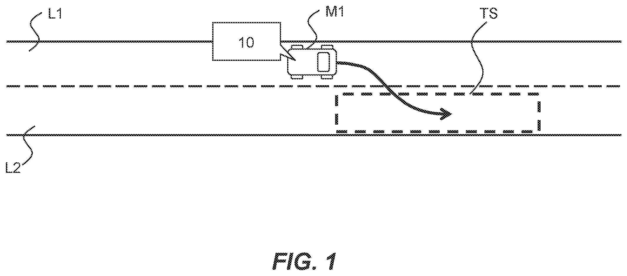
is a diagram illustrating an outline of a lane change;
is a diagram illustrating a first scene assumed by an embodiment;
is a diagram illustrating an outline of the embodiment;
is a diagram illustrating the outline of the embodiment;
is a diagram illustrating a second scene assumed by the embodiment;
is a diagram illustrating the outline of the embodiment;
is a diagram illustrating a configuration example of a driving support apparatus according to the embodiment;
is a flowchart illustrating processing flow particularly relevant to the embodiment;
is a diagram for explaining processing of step S 11 shown in ;
is a diagram for explaining processing of step S 12 shown in ;
is a diagram for explaining processing of step S 13 shown in ; and
is a diagram for explaining a numerical analysis performed by an inventor of the present disclosure.
DESCRIPTION OF EMBODIMENT
An embodiment of the present disclosure will now be described with reference to the drawings. In the drawings, the same or corresponding parts are denoted by the same reference numerals, and the description thereof will be simplified or omitted.
1. Outline of Embodiment
1-1. Lane Change
is a diagram illustrating an outline of a lane change. shows a vehicle M 1 . The vehicle M 1 travels by autonomous driving or manual driving by a driver. A driving support apparatus 10 according to the embodiment is mounted on the vehicle M 1 . The driving support apparatus 10 executes control to support a traveling by the autonomous driving or manual driving by the driver in the vehicle M 1 . The driving support control by the driving support apparatus 10 includes vehicle control for lane change.
The vehicle M 1 is traveling in the first lane L 1 . In the embodiment, a lane change from a first lane L 1 to a second lane L 2 is considered. In the vehicle control for this lane change, a target space TS is set in the second lane L 2 . When the target space TS is set, steering control for moving from the first lane L 1 to the target space TS is performed.
1-2. Features of Lane Change
1-2-1. First Feature
is a diagram illustrating a first scene assumed by the embodiment. In , vehicles M 2 and M 3 are depicted in addition to the vehicle M 1 . The vehicle M 2 is a vehicle traveling ahead of the vehicle M 1 in the first lane L 1 (that is, a preceding vehicle). The vehicle M 3 is a vehicle traveling in the second lane L 2 . The vehicle M 3 is a vehicle that will travel behind the vehicle M 1 when the vehicle M 1 moves to the target space TS (that is, a following vehicle in the future).
In the embodiment, a speed of traffic stream is considered for each lane. The speed of traffic stream of the first lane L 1 shown in is referred to as a “speed V L1 ”, and the speed of the traffic stream of the second lane L 2 is referred to as a “speed V L2 ”. The speed V L1 is, for example, a speed V M1 of the vehicle M 1 . In another example, the speed V L1 is the speed V M2 of the vehicle M 2 . In yet another example, the speed V L1 is an average of the speed V M1 and the speed V M2 . When the speed V M1 and the speed V M2 are substantially equal to each other, the speed V M1 or the speed V M2 can be considered as the speed V L1 . When there is a difference between the speed V M1 and the speed V M2 , the average of the speed V M1 and the speed V M2 may be considered as the speed V L1 . The speed V L2 is, for example, a speed V M3 of the vehicle M 3 .
Note that the speed V M1 , the speed V M2 , and the speed V M3 are calculated from the time series for the past “t” seconds. For example, the speed V M1 is calculated as an average of time-series date detected from a certain time point in the past to the current time point. The speed V M2 and the speed V M3 are estimated by using a probability model such as a Kalman filter.
are diagrams illustrating an outline of the embodiment. When the speed V L2 is higher than the speed V L1 (V L2 >V L1 ), it is desirable to accelerate the vehicle M 1 during the lane change to increase the speed V M1 to the speed V L2 . The reason for this is that after the lane change, an occurrence of an influence is predicted on the traffic stream of the second lane L 2 , such as forcing the vehicle M 3 to decelerate. However, when the length of a front space FS of the vehicle M 1 in the first lane L 1 (that is, a distance from the vehicle M 1 to the vehicle M 2 ) is short, the vehicle M 1 cannot be sufficiently accelerated in the first lane L 1 ( ).
Therefore, in the embodiment, in the vehicle control for the lane change, control (deceleration control) for decelerating the vehicle M 1 in the first lane L 1 is temporarily performed. As shown in , when the deceleration control is temporarily performed, the front space FS is expanded to become the front space FS*. As a result, it is possible to perform control (acceleration control) for accelerating the vehicle M 1 in the first lane L 1 and steering control for moving from the first lane L 1 to the target space TS. That is, according to the embodiment, in the case where the speed V L2 is higher than the speed V L1 , the lane change can be performed even when the length of the front space FS is short.
1-2-2. Second Feature
is a diagram illustrating a second scene assumed by the embodiment. In , a vehicle M 4 is depicted in addition to the vehicles M 1 , M 2 and M 3 . The vehicle M 4 is a vehicle that travels behind the vehicle M 1 in the first lane L 1 (that is, a following vehicle). When the vehicle M 4 is present, the speed V L1 is the speed V M1 , the speed V M2 , or the speed V M4 . If there is a difference among these speeds, the average of the speed V M1 , the speed V M2 and the speed V M4 can be considered as the speed V L1 .
is a diagram for explaining the outline of the embodiment in the second scene. When the deceleration control is performed in a case where the vehicle M 4 is present, the length of a rear space RS of the vehicle M 1 in the first lane L 1 (that is, the distance from the vehicle M 1 to the vehicle M 4 ) is reduced. It is not desirable that the length of the rear space RS becomes extremely short. The reason for this is that the occurrence of an influence on the traffic stream of the first lane L 1 , such as forcing the vehicle M 4 to decelerate, is predicted. Therefore, in the embodiment, the decrement control may be executed only when the length of the rear space RS is sufficient. That is, when the length of the rear space RS is not sufficient, the execution of the deceleration control may be stopped.
2. Driving Support Apparatus
2-1. Configuration Example
is a block diagram illustrating an example configuration of a driving support apparatus according to an embodiment. In the example shown in , the driving support apparatus 10 includes an external sensor 11 , an internal sensor 12 , a global navigation satellite system (GNSS) receiver 13 , and a map database 14 . The driving support apparatus 10 also includes a human machine interface (HMI) unit 15 , various actuators 16 , and a controller 17 .
The external sensor 11 is a device that detects surrounding circumstances of the vehicle M 1 . Examples of the external sensor 11 include a radar sensor and a camera. The radar sensor detects objects around the vehicle M 1 using radio waves (for example, millimeter waves) or light. The object includes a static object and a moving body. Examples of the static object include a guard rail and a building. Moving bodies include walkers, bicycles, motorcycles and vehicles other than the vehicle M 1 . The camera images a situation outside the vehicle M 1 . The camera images at least a front side of the vehicle M 1 . The camera may include a camera for imaging the rear and side of the vehicle M 1 .
The internal sensor 12 is a device that detects a driving state of the vehicle M 1 . Examples of the internal sensor 12 include a vehicle speed sensor, an acceleration sensor, and a yaw rate sensor. The vehicle speed sensor detects the speed of the vehicle M 1 (i.e., the speed V M1 ). The acceleration sensor detects acceleration (or deceleration) of the vehicle M 1 . The yaw rate sensor detects a yaw rate around a vertical axis of the center of gravity of the vehicle M 1 .
The GNSS receiver 13 is a device that receives signals from three or more artificial satellites. The GNSS receiver 13 is also a device that acquires information on the position of the vehicle M 1 . The GNSS receiver 13 calculates the position and attitude (direction) of the vehicle M 1 based on the received signal.
The map database 14 is a database that stores map information. Examples of the map information include positional information on roads, information on road shapes (for example, types of curves and straight lines), and positional information on intersections and construction. The map information includes information on traffic regulation such as a legal speed. The map database 14 is formed in an in-vehicle memory device (for example, a hard disk or a flash memory). The map database 14 may be formed in a computer of an external device (for example, an external server) capable of communicating with the vehicle M 1 .
The information on the surrounding circumstances of the vehicle M 1 acquired by the external sensor 11 , the information on the driving state acquired by the internal sensor 12 , the information on the position and posture acquired by the GNSS receiver 13 , and the map information are included in the “information on a driving environment” of the vehicle M 1 . As the information on the driving environment particularly related to the embodiment, the information on the surrounding circumstances of the vehicle M 1 includes information on a space SP in the second lane L 2 , information on the speed of traffic stream (i.e., the speed V L2 ) in the second lane L 2 , information on the speed of traffic stream (i.e., the speed V L1 ) in the first lane L 1 , and information on the distance (a front inter-vehicular distance) D 12 from the vehicle M 1 to the vehicle M 2 in the first lane.
The HMI unit 15 is a user interface for providing information to the driver of the vehicle M 1 and receiving information from the driver. The HMI unit 15 includes, for example, an input device, a display device, a speaker, and a microphone. Examples of the input device include a touch panel, a keyboard, a switch, and a button. The information provided to the driver includes information on the driving environment of the vehicle M 1 and information on driving support control that is being executed. Information is provided to the driver using a display device and a speaker. Information is received from the driver by using an input device and a microphone.
The various actuators 16 are actuators included in driving devices (drive, brake and steering devices) of the vehicle M 1 . Examples of the various actuators 16 include a drive actuator, a braking actuator, and a steering actuator. The drive actuator drives the vehicle M 1 . The braking actuator applies a braking force to the vehicle M 1 . The steering actuator steers tires of the vehicle M 1 .
The controller 17 includes a microcomputer having at least one processor 17 a and at least one memory 17 b . At least one program is stored in the memory 17 b . The at least one program includes a driving support program according to an embodiment. Various information including the information on the driving environment of the vehicle M 1 is also stored in the memory 17 b . When the program stored in the memory 17 b is read and executed by the processor 17 a , various functions of the controller 17 are realized. The various functions include a function of performing driving support control of the vehicle M 1 using the various actuators 16 .
2-2. Processing Example
is a flowchart showing a flow of processing (the vehicle control processing for the lane change) particularly related to the embodiment, which is performed by the controller 17 (the processor 17 a ). The processing routine shown in is repeatedly executed at a predetermined control cycle when the driving support program for the lane change is activated in the case where the speed V L2 is higher than the speed V L1 , for example.
In the routine shown in , it is first determined whether or not there is a space LCS in which a lane change is possible in the second lane L 2 (step S 11 ). is a diagram for explaining the processing in step S 11 . In , the space SP in the second lane L 2 is drawn. The space SP is, for example, a space between the vehicle M 3 and a vehicle M 5 in the second lane L 2 . The space SP is also a space existing on the side of the vehicle M 1 . Note that the vehicle M 5 may not exist on the second lane L 2 . When the vehicle M 5 does not exist, the front space of the vehicle M 3 in the second lane L 2 corresponds to the space SP.
For example, when the space SP satisfies the condition of following formula (1), it is determined that the space SP is a space LCS in which a lane change is possible. L SP >L M1 +L F +L R (1)
In the formula (1), L SP is a length of the space SP, L M1 is a vehicle length of the vehicle M 1 , L F is the length of a front space required for lane change, and L R is the length of a rear space required for lane change. The lengths L F and L R are variables that depend on the speed V M1 .
When the determination result of the step S 11 is positive, it is determined whether or not the front space FS capable of accelerating the vehicle M 1 exists on the first lane L 1 (step S 12 ). is a diagram for explaining the processing in step S 12 . In , the front space FS is depicted. The length of the front space FS is substantially equal to the distance D 12 from the vehicle M 1 to the vehicle M 2 . When the vehicle M 1 moves to the second lane L 2 while accelerating from the first lane L 1 , the distance D 12 needs to be a distance at which the vehicle M 1 does not come into contact with the vehicle M 2 and the driver of the vehicle M 1 does not feel fear or pressure caused by the acceleration of the vehicle M 1 .
The distance at which the vehicle M 1 does not contact the vehicle M 2 can be represented by a value TTC (D 12 /V M1 −V M2 ) obtained by dividing the distance D 12 by the relative speed. In the lane change accompanied by acceleration, the vehicle M 1 and the vehicle M 2 come closest to each other at the moment when the overlap ratio in the lateral position direction of both becomes 0. This moment is referred to as minimum TTC. In the embodiment, the minimum TTC at which the driver of the vehicle M 1 can safely change lanes is set as the front safe time TTC OPT_F .
Here, the time TLC required for the lane change is considered. Then, the time required for the vehicle M 2 to reach the boundary BD between the first lane L 1 and the second lane L 1 after the steering of the vehicle M 2 toward the second lane L 1 is considered to be half of the time TLC (i.e., TLC/2). In the embodiment, it is assumed that the vehicle M 1 accelerates at a maximum acceleration rate a max . Then, the vehicle M 1 approaches the vehicle M 1 during a period from the start of steering of the vehicle M 1 until the vehicle M 2 reaches the boundary BD. The shortened inter-vehicular distance D ACC is expressed by the following formula (2). D ACC ={V M1 *( TLC/ 2)+ a max *(½)*( TLC/ 2) 2 } (2)
In addition, when the vehicle M 1 accelerates at the maximum acceleration rate a max , the front safe time TTC OPT_F also fluctuates during a period from when the steering of the vehicle M 1 is started to when the vehicle M 1 reaches the boundary BD. Considering the variation of the front safe time TTC OPT_F , it is understood that the vehicle M 1 does not come into contact with the vehicle M 2 and the driver of the vehicle M 2 does not feel fear or pressure caused by acceleration of the vehicle M 1 if the distance D 12 satisfies the condition of the following formula (3). D 12 =D ACC +TTC OPT_F *a max *( TLC/ 2) (3)
In the processing of Step S 12 , when the distance D 12 satisfies the condition of the following formula (4), it is determined that the front space FS capable of accelerating the vehicle M 1 exists on the first lane L 1 . D 12 ≥D ACC +TTC OPT_F *a max *( TLC/ 2) (4)
The processing executed when the determination result in step S 12 is positive will be described later. When the determination result of step S 12 is negative, it is determined whether or not a rear space RS capable of decelerating the vehicle M 1 is present on the first lane L 1 (step S 13 ). is a diagram for explaining the processing in step S 13 . In , a rear space RS is depicted. The length of the rear space RS is substantially equal to a distance D 14 from the vehicle M 1 to the vehicle M 4 . When the vehicle M 1 decelerates at the first lane L 1 , the distance D 14 needs to be a distance at which the vehicle M 1 does not come into contact with the vehicle M 4 and does not give the driver of the vehicle M 4 a feeling of approach due to the deceleration of the vehicle M 1 .
In the embodiment, the TTC that does not give a sense of approach to the driver of the vehicle M 4 is set as the rear safety time TTC OPT_R . On the other hand, the distance at which the vehicle M 1 does not contact the vehicle M 4 can be represented by a value TTC (D 14 /V M4 −V M1 ) obtained by dividing the distance D 14 by the relative speed. In the processing of step S 13 , when the condition of following formula (5) is satisfied, it is determined that the rear space RS capable of decelerating the vehicle M 1 is present on the first lane L 1 . TTC ( D 14 /V M4 −V M1 )≥ TTC OPT_R (5)
If the determination result of step S 13 is positive, a determination instruction is transmitted (step S 14 ). The deceleration instruction is an instruction for temporarily decelerating the vehicle M 1 , and is transmitted to the braking device of the vehicle M 1 . Note that the declaration is optional. When the processing of step S 14 is executed, the processing of step S 11 and subsequent processing are executed. That is, when the determination result of the step S 13 is positive, the vehicle M 1 is temporarily decelerated and the space LCS is searched.
If the determination result in step S 12 is positive, an acceleration and steering instruction is transmitted (step S 15 ). The acceleration and steering instruction is an instruction for moving from the first lane L 1 to the target space TS (i.e., lane change). The acceleration instruction is transmitted to the driving device of the vehicle M 1 , and the steering instruction is transmitted to the steering device of the vehicle M 1 .
3. Assessment Result by Numerical Analysis
is a diagram for explaining a numerical analysis performed by an inventor of the present disclosure. This numerical analysis was performed by setting the parameter conditions shown in the following Table 1 with the scene described in as a premise scene.
TABLE 1
Parameter Value Unit
VL1 80 km/h
VL2 100 km/h
D12(distance from M1 to M2) 10 m
D14(distance from M1 to M4) 10 m
D13(distance from M1 to M3) 37 m
Maximum deceleration 0.7 m/s{circumflex over ( )}2
Maximum acceleration 1.4 m/s{circumflex over ( )}2
Allowable mimimum TTC 6 sec
LSP 25 m
TLC 6 sec
“Deceleration and acceleration” shown in corresponds to the temporal change of the inter-vehicular distance according to the method of the embodiment, and “only acceleration” corresponds to that according to the comparative example. Further, the distance D 12 shown in and Table 1 is based on the direction in which the first lane L 1 extends, and the distance D 13 is based on the direction in which the second lane L 2 extends. Note that the distance D 14 is omitted in .
When the minimum inter-vehicular distance and the minimum TTC during the lane change were calculated from the time change in , the assessment results shown in the following Table 2 were obtained.
TABLE 2
Deceleration Only
Evaluation result & Acceleration Acceleration Unit
D14_MIN(minimum 9.12 10 m
inter-vehicular
distance from M1 to M4)
Minimum TTC 14 10.3 — sec
D12_MIN(minimum 10.03 10 m
inter-vehicular
distance from M1 to M2)
Minimum TTC 12 6.8 — sec
D13_MIN(minimum 54.54 20.14 m
inter-vehicular
distance from M1 to M3)
Minimum TTC 13 6.06 5.56 sec
From the results of Table 2, it was found that in both cases of “only acceleration” and “deceleration and acceleration”, the minimum TTC (the minimum TTC 12 and the minimum TTC 14 ) exceeds the allowable minimum TTC (6.0 seconds) for the vehicles M 2 and M 4 on the first lane L 1 . On the other hand, it was found that in the case of “deceleration and acceleration”, the minimum TTC 13 exceeds the allowable minimum TTC (6.0 seconds) for the vehicle M 2 in the second lane L 3 , whereas in the case of “only acceleration”, the minimum TTC 13 falls below the allowable minimum TTC. Therefore, in the case of the scene described in and the parameter conditions shown in Table 1, it was shown that the method of the embodiment is particularly effective.
Figures (12)
Citations
This patent cites (23)
- US10793147
- US10870349
- US10953883
- US10981569
- US11014563
- US11072334
- US11267473
- US11279360
- US11827218
- US2018/0043935
- US2019/0241195
- US2019/0384305
- US2020/0070889
- US2020/0247400
- US2021/0171042
- US2021/0188264
- US2021/0201668
- US2021/0269040
- US2023/0021000
- US2023/0077036
- US2023/0360534
- US2024/0067214
- US2017-021506