Abstract
A storage device system includes a storage case having a base and a cover coupled to the base, and a plurality of insertable bins removably positioned within an interior of the base. The plurality of insertable bins includes a first bin having a first height and a set of second bins each having a second height. The set of second bins is configured to be stackable and have a stacked height when stacked. A depth of the interior of the base, the first height, and the stacked height are equal.
Claims (18)
1. A storage device system, comprising: a soft-sided storage device comprising: flexible sidewalls; a rigid bottom member coupled to the flexible sidewalls, the flexible sidewalls and the rigid bottom member collectively defining a storage compartment; and a rigid bottom surface defined by the rigid bottom member; and a rigid storage device comprising: an upper surface; and a plurality of connection recesses, each connection recess of the plurality of connection recesses comprising a first wing extending in a first direction and a second wing extending in a second direction opposite the first direction, the first wing and the second wing each offset and extending above a lower surface of the respective female coupler, the first wing and the second wing configured for arresting engagement with the rigid bottom surface of the soft-sided storage device, each of the first wing and the second wing defining a surface that faces downward towards and is parallel to a recessed surface of the respective connection recess.
7. A storage device system, comprising: a soft-sided storage device including a rigid bottom; a rigid storage device including a top that interfaces with the bottom of the soft-sided storage device; and a latch assembly operable to secure the soft-sided storage device and the rigid storage device together, the soft-sided storage device and the rigid storage device being carryable as a coupled unit; wherein one of the bottom or the top includes a projection and the other of the bottom or the top defines a recess configured to receive the projection, and wherein the projection is configured to engage the other of the bottom or the top defining the recess to interface the rigid storage device and the soft-sided storage device, and wherein the projection defines two channels arranged to receive and engage two wings formed by the other of the bottom or the top defining the recess, and wherein a first channel of the two channels is defined at least in part by a first projection portion extending from the projection, the first projection portion defining a first surface that faces towards and is parallel to one of the bottom or the top, and wherein a first wing of the two wings defines a second surface that faces towards and is parallel to the other of the bottom or the top, the first surface and the second surface interfacing when the soft-sided storage device and the rigid storage device are secured together.
14. A storage device system, comprising: a rigid storage device comprising an upper surface; and a soft-sided storage device comprising: flexible sidewalls; a rigid bottom member coupled to the flexible sidewalls, the flexible sidewalls and the rigid bottom member collectively defining a storage compartment; and a rigid bottom surface defined by the rigid bottom member; and a plurality of projections extending from the rigid bottom surface, each of the plurality of projections comprising a first projection portion extending from the projection in a first direction and a second projection portion extending from the projection in a second direction opposite the first direction, the first projection portion and the second projection portion each offset and extending below the rigid bottom surface, the first projection portion and the second projection portion configured for arresting engagement with the upper surface of the rigid storage device, each of the plurality of projections defining a first channel between the first projection portion and the rigid bottom surface and a second channel between the second projection portion and the rigid bottom surface, each of the first projection portions and the second projection portions defining a surface that faces upward towards and is parallel to the rigid bottom surface.
Show 15 dependent claims
2. The storage device system of claim 1 , the plurality of connection recesses comprising two rows of connection recesses each parallel to a front of the rigid storage device, wherein each of the two rows of connection recesses comprises two connection recesses of the plurality of connection recesses.
3. The storage device system of claim 2 , comprising a handle coupled to the front of the rigid storage device.
4. The storage device system of claim 1 , comprising a latch assembly operable to secure the soft-sided storage device and the rigid storage device together, the latch assembly actuating between a locked configuration and an unlocked configuration, wherein the latch assembly obstructs movement of the rigid storage device relative to the soft-sided storage device when in the locked configuration.
5. The storage device system of claim 4 , the latch assembly comprising: a locking aperture defined by the upper surface of the rigid storage device; a latch member coupled to the soft-sided storage device, the latch member configured to be received in the locking aperture; and a biasing element that biases the latch member into the locking aperture when the rigid storage device and the soft-sided storage device are coupled together in the locked configuration.
6. The storage device system of claim 1 , the plurality of connection recesses comprising a first connection recess configured to engage with two distinct projections extending from the rigid bottom surface of the soft-sided storage device.
8. The storage device system of claim 7 , wherein the latch assembly includes a latch member supported on one of soft-sided storage device or the rigid storage device, and wherein the latch member is configured to selectively engage a latch aperture defined by the other of the soft-sided storage device or the rigid storage device to secure the soft-sided storage device and the rigid storage device together.
9. The storage device system of claim 8 , wherein the channels receive the wings in a first direction and inhibits the soft-sided storage device from being disconnected from the rigid storage device except in a second direction opposite the first direction, and wherein the latch member engages the latch aperture to inhibit movement of the projection relative to the wings in the second direction.
10. The storage device system of claim 9 , wherein the first and second directions are parallel to a top surface of the top.
11. The storage device system of claim 8 , wherein the latch assembly includes a biasing member arranged to bias the latch member into engagement with the latch aperture when the rigid storage device and the soft-sided storage device are connected.
12. The storage device system of claim 7 , wherein the soft-sided storage device further includes a handle, and wherein the coupled unit of the soft-sided storage device and the rigid storage device are carryable by the handle.
13. The storage device system of claim 12 , wherein the handle is positioned above a center of gravity of the coupled unit of the soft-sided storage device and the rigid storage device.
15. The storage device system of claim 14 , the rigid bottom member extending along a longitudinal axis, each of the first channel and the second channel extending parallel to the longitudinal axis of the rigid bottom member.
16. The storage device system of claim 14 , comprising a latch assembly operable to secure the soft-sided storage device and the rigid storage device together, the soft-sided storage device and the rigid storage device being carryable as a coupled unit.
17. The storage device system of claim 12 , the latch assembly comprising: a latch member coupled to the soft-sided storage device; and a locking aperture defined by the upper surface of the rigid storage device, the locking aperture configured to receive the latch member, wherein the latch assembly obstructs movement of the rigid storage device relative to the soft-sided storage device when the latch member is received in the locking aperture.
18. The storage device system of claim 17 , the plurality of projections comprising two rows of projections each parallel to a front of the soft-sided storage device, wherein each of the two rows of projections comprises two projections of the plurality of projections.
Full Description
Show full text →
CROSS-REFERENCE TO RELATED APPLICATIONS
This application is a continuation of U.S. application Ser. No. 15/375,492, filed Dec. 12, 2016, which claims priority to U.S. Provisional Patent Application No. 62/267,071, filed on Dec. 14, 2015, each of which are hereby incorporated by reference in its entirety.
BACKGROUND
The present invention relates to storage devices, including bags, storage totes, tool boxes and organizers.
Tool storage devices are often used to transport tools and accessories. Tool storage devices include soft-sided storage devices such as a tool bags, and rigid storage devices such as tool boxes and organizers. Soft-sided storage devices include walls made of flexible material and typically have a bottom made of a rigid material. Rigid storage devices include a rigid base and a rigid cover coupled thereto. The rigid base may include dividers and storage compartments for storing and organizing tools and accessories.
SUMMARY
In one embodiment, the invention provides a storage device system including a storage case having a base and a cover coupled to the base, and a plurality of insertable bins removably positioned within an interior of the base. The plurality of insertable bins includes a first bin having a first height and a set of second bins each having a second height. The set of second bins is configured to be stackable and have a stacked height when stacked. A depth of the interior of the base, the first height, and the stacked height are equal.
In another embodiment, the invention provides a storage device system including a storage case having a base and a cover coupled to the base, and a plurality of insertable bins removably positioned within an interior of the base. The insertable bins include a first bin and a second bin configured to be stackable. The first bin has a ledge formed on an inner surface of the first bin. The ledge is configured to engage and support the second bin when the second bin is stacked on the first bin. The second bin has a rib on an outer surface to inhibit suctioning when the second bin is stacked on the first bin.
In yet another embodiment, the invention provides a storage device system including a soft-sided storage device having a rigid bottom, and a rigid storage device having a top that interfaces with the bottom of the soft-sided storage device. The storage device system further includes a latch assembly operable to secure the soft-sided storage device and the rigid storage device together. The soft-sided storage device and the rigid storage device being carryable as a coupled unit.
Other aspects of the invention will become apparent by consideration of the detailed description and accompanying drawings.
BRIEF DESCRIPTION OF THE DRAWINGS
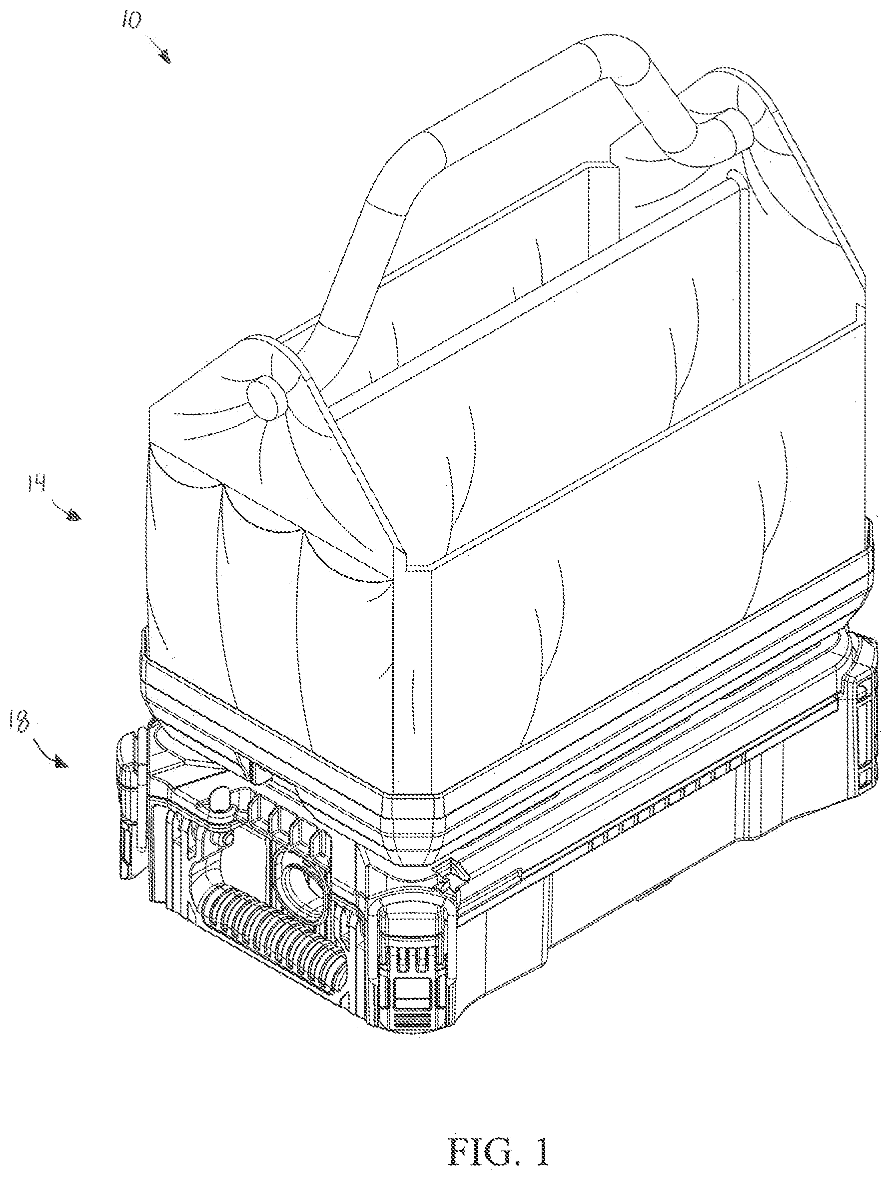
is a perspective view of a storage device system including a soft-sided storage device coupled to a rigid storage device.
is a perspective view of the soft-sided storage device of .
is a bottom perspective view of the soft-sided storage device of .
is another bottom perspective view of the soft-sided storage device of .
is a top perspective view of the rigid storage device of .
is a top view of the rigid storage device of .
is an enlarged cross-sectional view of a portion of the storage device system of , illustrating a bottom of the soft-sided storage device disengaged from a top of the rigid storage device.
is an enlarged cross-sectional view of the portion of the storage device system shown in , illustrating the bottom of the soft-sided storage device engaged with the top of the rigid storage device.
is an enlarged cross-sectional view of a portion of the storage device system of , illustrating a latch assembly in a locking position.
is an enlarged cross-sectional view of the portion of the storage device system shown in , illustrating the latch assembly in an unlocking position.
is a perspective view of the rigid storage device of , illustrating a cover in an open position.
is a top perspective view of a bin for use with the storage case.
is a top view of the bin of .
is a side view of the bin of .
is a bottom view of the bin of .
is an exploded perspective view of the bin of .
illustrates two relatively short bins stacked on top of one another.
illustrates a relatively tall bin.
is an enlarged view of portions of the two relatively short bins of stacked together.
is an enlarged view of a portion of the storage case in the open position.
Before any embodiments of the invention are explained in detail, it is to be understood that the invention is not limited in its application to the details of construction and the arrangement of components set forth in the following description or illustrated in the following drawings. The invention is capable of other embodiments and of being practiced or of being carried out in various ways. Also, it is to be understood that the phraseology and terminology used herein is for the purpose of description and should not be regarded as limiting.
DETAILED DESCRIPTION
illustrates a storage device system 10 including a soft-sided storage device 14 , such as soft-sided bag, removably coupled to a hard-sided or rigid storage device 18 , such as a rigid storage case (e.g., a rigid tool box or organizer).
With reference to , the bag 14 includes a rigid or hard bottom member 22 (e.g., thermoform plastic, etc.) and flexible sidewalls 26 cooperating to define a storage compartment 30 . The sidewalls 26 define an open top 34 for access to the storage compartment 30 . A handle 38 is connected between opposite sidewalls 26 and is engageable by a user to carry the bag 14 .
One or more interface or connection projections 46 are provided on the bottom member 22 . In the illustrated embodiment, each projection 46 extends from a bottom surface 50 of the bottom member 22 and is configured to cooperate with a connection recess 54 ( ) on the storage case 18 to interface and connect the bag 14 to the storage case 18 . In the illustrated embodiment, each projection 46 is formed integrally with the bottom member 22 , for example, in a thermoforming process. Each projection 46 has a channel 58 on each side of the projection 46 , including a first channel 58 and a second channel 58 , extending parallel to a longitudinal axis A of the bottom member 22 , as best shown in . Each channel 58 has a front, open end 62 and a back, closed end 66 along the axis A. One or more projections 46 includes projection portions 47 , including a first projection portion 47 extending from the respective projection 46 in a first direction and a second projection portion 47 extending from the respective projection 46 in a second direction, and the projections 46 define channels 58 . Each projection 46 has a planar surface 70 with a generally rectangular shape. In other embodiments, the planar surface 70 may be another shape, e.g., circular, triangular, etc. In the illustrated embodiment, there are six projections 46 arranged in three rows of two along the axis A. In other embodiments, the bag 14 may include fewer or more projections 46 , and/or the projections 46 may be arranged in different patterns. The projections 46 are arranged such that the bag 14 can be supported on a surface by the projections 46 through contact with the planar surfaces 70 .
The bag 14 further includes a latch assembly 78 including a latch member 82 , as shown in . The latch assembly 78 is supported by the bottom member 22 within a latch passage 86 defined in the bottom member 22 . The latch member 82 includes a grip portion 90 and an interference portion 94 . The latch member 82 is slidingly movable along an axis perpendicular to the longitudinal axis A of the bottom member 22 within the latch passage 86 . The interference portion 94 selectively protrudes from the latch passage 86 through a slot 98 defined in the bottom surface 50 of the bottom member 22 . The interference portion 94 has a tapered surface 102 ( ) at a distal end thereof. The latch member 82 is movable between a first or locking position ( ) in which the interference portion 94 extends through the slot 98 , and a second or unlocking position ( ) in which the interference portion 94 is retracted into the latch passage 86 and does not extend through the slot 98 . The latch assembly 78 further includes a biasing member 106 (e.g., a compression spring) arranged to bias the latch member 82 into the locking position ( ). The latch member 82 may be urged against the biasing member 106 to the unlocking position ( ) by pushing on the grip portion 90 . In the locking position, the interference portion 94 does not extend beyond the planar surfaces 70 of the projections 46 .
With reference to , the storage case 18 includes a base 114 and a top or cover 118 . The cover 118 is movably coupled to the base 114 between a closed position ( ) and an open position ( ). In the illustrated embodiment, the cover 118 is pivotally coupled to the base 114 by a hinge 122 . The cover 118 includes cover latches 126 to releasably secure the cover 118 in the closed position. The storage case 18 also includes a side handle 130 to facilitate independently carrying the storage case 18 .
With continued reference to , a top surface 134 of the cover 118 defines the connection recesses 54 that receive and cooperate with the projections 46 . In the illustrated embodiment, the connection recesses 54 include two rows of two small recesses 54 a corresponding to two rows of two projections 46 and one large recess 54 b corresponding to a row of two projections 46 . In other embodiments, the cover 118 may include different numbers of patterns of recesses 54 , depending on the arrangement of the projections 46 on the bag 14 . When the projections 46 are received in the connection recesses 54 , the bottom surface 50 of the bottom member 22 is arranged to contact and be supported by the top surface 134 of the cover 118 .
Two interference projections or wings 142 extends into each connection recess 54 parallel to a longitudinal axis B of the cover 118 on opposite sides of the connection recess 54 from one end of the connection recess 54 . Each of the wings 142 corresponds to and is configured to cooperate with a corresponding one of the channels 58 of the projection 46 received by the respective connection recess 54 . Each of the wings 142 has a length that extends approximately half the connection recess 54 to define a first portion 146 of the connection recess 54 and a second portion 150 opposite the wings 142 , which remains open. The second portion 150 of each connection recess 54 is sized to receive one of the projections 46 generally perpendicular to the longitudinal axis B into a first, disconnected position ( ). In the disconnected position, the projections 46 are oriented within the connection recesses 54 such that the open ends 62 of the channels 58 are nearer to the wings 142 than the closed ends 66 . Once in the disconnected position, the bottom member 22 may be slid relative to the cover 118 parallel the longitudinal axes A, B in a first direction 152 toward the wings 142 such that the wings 142 are received within the channels 58 in a second, interfaced or connected position ( ). The wings 142 and the projections 46 engage within the connection recesses 54 to interface and connect the bottom member 22 with the cover 118 and prevent disconnection of the bottom member 22 from the cover 118 , except in a second direction 154 opposite the first direction 152 and generally parallel to the longitudinal axes A, B. The wings 142 and the channels 58 engage one another perpendicular to the longitudinal axes A, B (i.e., perpendicular to the top surface 134 of the cover 118 and the bottom surface 50 of the bottom member 22 ) when carrying the bag 14 and the storage case 18 as a single unit via the handle 38 of the bag 14 (see ).
With continued reference to , the top surface 134 of the cover 118 further defines an interference or locking aperture 158 . In the illustrated embodiment, the locking aperture 158 is located at one end of the cover 118 . The end of the cover 118 has a sloped surface 162 adjacent the locking aperture 158 . The locking aperture 158 is elongate and extends transverse to the longitudinal axis B of the cover 118 parallel to a short side of the cover 118 . The locking aperture 158 is located such that when the bottom member 22 and the cover 118 are in the connected position, the locking aperture 158 is aligned with the interference portion 94 of the latch member 82 . The locking aperture 158 is sized to receive and engage the interference portion 94 when the latch member 82 is in the locking position ( ). When the interference portion 94 is engaged with the locking aperture 158 in the locking position, the latch member 82 obstructs movement of the bottom member 22 relative to the cover 118 from the connected position to the disconnected position in the second direction 154 , thereby inhibiting disconnection of the bag 14 from the storage case 18 . In particular, the interference portion 94 interferes with the cover 118 within the locking aperture 158 such that the wings 142 cannot be removed from the channels 58 of the projections 46 in the second direction 154 .
A user may couple the soft-sided bag 14 to the rigid storage case 18 to carry as a coupled unit by first, inserting the connection projections 46 of the bottom member 22 in a direction perpendicular to the cover 118 and into the second portion 150 of the connection recesses 54 of the cover 118 such that the cover 118 supports the bag 14 in the disconnected position ( ). The bottom member 22 and the cover 118 are oriented such their longitudinal axes A, B are parallel, and the latch assembly 78 is nearest the end of the cover 118 defining the locking aperture 158 . The bag 14 (i.e., the bottom member 22 ) is then manually slid in the first direction 152 such that the wings 142 are received in the channels 58 through the open end 62 of the channels 58 until the wings 142 abut the closed end 66 of the channels 58 in the connected position ( ). As the bottom member 22 slides relative to the cover 118 from the disconnected position to the connected position, the latch member 82 , which is biased into the locking position ( ) by the biasing member 106 , is urged into the unlocking position ( ) by the sloped surface 162 of the cover 118 until aligned with the locking aperture 158 when in the connected position. The biasing member 106 then automatically biases the latch member 82 back into the locking position ( ) in which the interference portion 94 is received in and engages the locking aperture 158 . Alternatively, a user may urge the latch member 82 into the unlocking position ( ) by pushing on the grip portion 90 upwardly against the biasing force of the biasing member 106 . The user holds the latch member 82 in the unlocking position while sliding the bag 14 in the first direction 152 from the disconnected position to the connected position. Once in the connected position ( ), the user may release the latch member 82 , thereby allowing the latch member 82 to be biased into the locking position where the interference portion 94 is received in and engages the locking aperture 158 . The interference portion 94 of the latch member 82 extends into the locking aperture, thereby inhibiting relative movement of the bag 14 and the storage case 18 in the second direction 154 parallel to the longitudinal axes A, B. Accordingly, the latch assembly 78 and the locking aperture 158 cooperate to secure the soft-sided bag 14 and the rigid storage case 18 in the connected position as a unit to be carried by the handle 38 of the bag 14 . The handle 38 is positioned such that when the bag 14 and the storage case 18 are coupled as a unit, the handle 38 is above a center of gravity of the coupled unit.
When the soft-sided bag 14 and the rigid storage case 18 are coupled together, the user may quickly decouple them to carry or access each of the storage devices 14 , 18 separately. The user first urges the latch member 82 into the unlocking position ( ) by pushing on the grip portion 90 upwardly against the biasing force of the biasing member 106 . While holding the latch member 82 in the unlocking position, the user then slides the bag 14 relative to the cover 118 in the second direction 154 along the longitudinal axes A, B from the connected position ( ) to the disconnected position ( ). The wings 142 disengage from the channels 58 and the projections 46 are moved into the second portion 150 of the connection recesses 54 , allowing the bag 14 to be disconnected in a direction away from and perpendicular to the top surface 134 of the cover 118 .
The latch assembly 78 is dimensioned and constructed to be movable between the locking and unlocking positions to couple the bag 14 to the cover 118 . The latch assembly 78 does not interfere with opening the storage case 18 so that the storage case 18 on the bottom will still be able to be opened with the soft-sided bag 14 attached to the cover 118 .
It should be understood that, in other constructions, multiple latch assemblies 78 and corresponding locking apertures 158 may be provided on the bag 14 and the storage case 18 . Such an arrangement may, for example, provide an increased connection between the storage devices 14 , 18 , balance or reduce the load on a given latch assembly, etc.
It should also be understood that, in other constructions, the latch assembly 78 and the locking aperture 158 may be reversed (e.g., the movable latch member 82 and the biasing member 106 may be supported on the cover 118 or the base 114 of the storage case 18 , and the locking aperture 158 may be defined by the bottom member 22 of the bag 14 ). Additionally or alternatively, the relative locations of the projections 46 and the recesses 54 may be reversed (e.g., the projections 46 may extend from the cover 118 of the storage case 18 , and the recesses 54 may be formed in the bottom member 22 of the soft-sided bag 14 ).
As shown in , the storage devices 14 , 18 have approximately the same perimeter dimensions. There is one pair of latch assembly 78 and locking aperture 158 at one end of the storage devices 14 , 18 . However, in alternate embodiments, the storage devices 14 , 18 may have different perimeter dimensions (e.g., the bag 14 is shorter than the storage case 18 ). In such embodiments, the bag 14 may have fewer projections 46 arranged such that the bag 14 may be connected to the storage case 18 in substantially the same manner as described above, except where one or more of the connection recesses 54 in the cover 118 does not receive a projection 46 . Additionally or alternatively, in some embodiments multiple soft-sided bags 14 having smaller dimensions than the storage case 18 may be simultaneously connected to the storage case 18 .
As shown in , a plurality of bins 170 A, 170 B, or inserts, are positioned within the base 114 . The base 114 includes a bottom wall 172 and sidewalls 174 extending from the bottom wall defining an interior 176 with a depth D. The bins 170 A, 170 B are independently removable from the storage case 18 when the storage case 18 is open (i.e., the cover 118 is in the open position), as shown in . The bins 170 A, 170 B include relatively tall, or deep, bins 170 A ( ) and relatively short, or shallow, bins 170 B ( ). The illustrated bins 170 A, 170 B are generally composed of plastic, but may alternatively be made of other materials. Each of the illustrated bins 170 A, 170 B is generally square in shape when viewed from above ( ). In other embodiments, the bins 170 A, 170 B may have other shapes (e.g., triangular, octagonal, circular, etc.). In the illustrated embodiment, the bins 170 A, 170 B are arranged within the base 114 as a grid of six (i.e., three rows of two). In other embodiments, the base 114 may be shaped and sized to receive a larger or smaller number of bins, and/or the bins 170 A, 170 B may be arranged within the base 114 in other patterns.
illustrate one of the relatively short bins 170 B in detail. The bin 170 B includes a bottom wall 186 and four sidewalls 190 extending generally perpendicularly from the bottom wall 186 . The bottom wall 186 and the sidewalls 190 define a storage recess or space 194 . Each of the relatively short bins 170 B has a height HB ( ).
The bin 170 B also includes ledges 198 formed on an inner surface 202 of the bin 170 B at each corner 206 between adjacent sidewalls 190 . The ledges 198 are positioned at a depth below a top edge 210 of the sidewalls 190 and a height above the bottom wall 186 . In the illustrated embodiment, the ledges 198 are located at a depth that is approximately a quarter of the height HB below the top edge 210 . In some embodiments the ledge 198 may extend around the perimeter of the sidewalls 190 . The ledges 198 are configured to engage and support another bin when, for example, two relatively short bins 170 B are stacked together, as best shown in . The bottom wall 186 at each corner 206 of the upper bin 170 B is supported on each ledge 198 of the lower bin 170 B. Each of the sidewalls 190 includes a lower, first portion 218 and an upper, second portion 222 that are stepped such that the first portion 218 has a smaller outer dimension than the second portion 222 . As such, the sidewalls 190 of the upper bin 170 B are partially received in the storage space 194 of the lower bin 170 B up to the ledges 198 of the lower bin 170 B. When stacked, the two relatively short bins 170 B have a stacked height SH ( ). In other embodiments, more than two bins 170 B may be stacked. Due to the top bin 170 B being partially received in the bottom bin 170 B, the stacked height SH is less than the total height of the two bins 170 B (i.e., two times the height HB of the bins 170 B).
The bin 170 B further includes ribs 230 formed on an outer surface 234 of the bin 170 B at the corners 206 between adjacent sidewalls 190 . Each of the ribs 230 protrudes outwardly from the outer surface 234 and extends down from the top edge 210 toward the bottom wall 186 . In the illustrated embodiment, each of the corners 206 has two ribs 230 . In some embodiments, ribs may be formed on the sidewalls 190 between the corners 206 in addition to or in place of the ribs 230 formed at the corners 206 .
As best shown in , when two or more bins 170 B are stacked, the ribs 230 protrude from the outer surface 234 of the upper bin 170 B to contact and engage the inner surface 202 of the lower bin 170 B to space apart the sidewalls 190 of the stacked bins 170 B. Accordingly, the ribs 230 help maintain a space or gap 238 between the stacked bins 170 B for airflow, thereby inhibiting the stacked bins 170 B from getting stuck together due to vacuum effects. In other words, the gap 238 provides fluid communication between a cavity formed between the inner surface 202 of the lower bin 170 B and the outer surface 234 of the bin 170 B below the ledge 198 of the lower bin 170 B and atmosphere, thereby inhibiting a vacuum from forming when the bins 170 B are stacked.
In some embodiments, such as the illustrated embodiment, the bin 170 B includes a track 242 formed on the inner surface 202 of the bin 170 B, as best shown in . The track 242 extends partially along two opposing sidewalls 190 and along the bottom wall 186 . The track 242 is configured to removably receive a dividing wall 246 , or partition, for dividing the storage space 194 into separate compartments. The illustrated dividing wall 246 splits the storage space 194 in half. In other embodiments, the track 242 and the dividing wall 246 may be positioned to split the storage space 194 into unequally sized compartments, or the bin 170 B may include multiple tracks for receiving multiple dividing walls. In some embodiments, the track 242 and the dividing wall 246 may be omitted. In the illustrated embodiment, the height of the dividing wall 246 inhibits a bin 170 B from being stacked on a bin 170 B with a dividing wall 246 . In other embodiments, the dividing wall 246 may have a height that does not interfere with stacking the bins 170 B.
illustrates one of the relatively tall bins 170 A. The relatively tall bin 170 A is substantially similar to the relatively short bins 170 B. However, the relatively tall bin 170 A has a height HA greater than the height HB of the relatively short bin 170 B. The stacked height SH of two relatively short bins 170 B, when stacked together, is generally equal to the height HA of the relatively tall bin 170 A. In addition, the height HB of the one relatively tall bin 170 A and the stacked height SH of two relatively short bins 170 B stacked together are each generally equal to the height or depth D of the base 114 of the storage device 18 .
As best shown in , a user may remove an upper bin of two stacked relatively short bins 170 B within the base 114 of the storage case 18 to allow access to the storage space 194 of the lower bin 170 B. Accordingly, the stacked bins 170 B within the storage device 18 provide additional storage and organizing space that can be easily reconfigured and arranged as necessary.
Although the invention has been described in detail with reference to certain preferred embodiments, variations and modifications exist within the scope and spirit of one or more independent aspects of the invention as described.
One or more independent features and/or independent advantages of the invention may be set forth in the claims.
Figures (20)
Citations
This patent cites (363)
- US2042387
- US2430200
- US2970358
- US3117692
- US3225865
- US3424334
- US3506321
- US3743372
- USD232798
- US3935613
- US3974898
- US4168076
- US4971201
- US5035445
- USD319016
- US5098235
- USD325324
- US5105947
- USD326815
- US5240264
- USD340167
- US5301829
- USD352208
- US5429260
- USD361511
- US5538213
- US5595228
- US5608603
- US5628443
- USD395533
- US5797617
- US5890613
- US5951037
- USD415393
- US5988473
- USD420860
- US6050660
- US6085925
- US6109627
- US6176559
- USD437669
- US6305498
- US6347847
- US6367631
- US6371320
- USD456972
- US6431580
- US6547347
- US6601930
- US6619772
- US6637707
- US6641013
- US6945546
- US6948691
- US6983946
- US7044484
- US7066475
- USD525789
- USD527225
- US7147243
- USD536580
- US7263742
- US7367571
- US7503569
- US7658887
- US7779764
- US7780026
- US7841144
- USD630851
- US8028845
- USD649350
- USD653832
- US8132819
- US8177463
- USD661858
- US8191910
- USD663952
- USD664354
- USD668869
- USD674605
- US8454033
- US8459495
- US8505729
- US8567796
- US8657307
- US8677661
- USD701696
- US8689396
- US8714355
- US8740010
- US8813960
- US8875888
- US8979100
- US8985922
- USD738105
- USD738106
- US9132543
- USD753394
- USD753395
- USD753396
- US9375835
- USD765974
- USD770179
- US9506489
- US9511491
- USD777426
- US9566990
- USD784089
- US9616562
- US9643629
- USD790221
- US9701443
- US9725209
- USD803631
- USD806483
- US9872562
- USD814187
- USD815831
- USD816334
- USD826510
- USD828671
- USD831352
- US10106180
- USD833744
- USD836995
- USD839681
- USD837515
- USD845080
- USD845081
- US10286542
- USD857387
- US10434638
- USD871013
- USD873085
- US10583962
- USD880252
- USD880951
- USD883752
- USD887788
- USD888422
- USD888503
- USD891193
- USD891195
- USD891875
- USD892565
- US10750833
- USD895375
- USD895966
- USD895967
- USD896517
- USD896518
- US10981696
- US2002/0000440
- US2002/0125072
- US2002/0171228
- US2003/0094393
- US2003/0115715
- US2003/0139080
- US2003/0146589
- US2003/0184034
- US2003/0205877
- US2004/0103494
- US2004/0195793
- US2004/0206656
- US2005/0062244
- US2005/0104308
- US2005/0139745
- US2006/0006770
- US2006/0027475
- US2006/0038367
- US2006/0119060
- US2006/0186624
- US2006/0254946
- US2007/0068757
- US2007/0090616
- US2007/0138041
- US2007/0145700
- US2007/0194543
- US2008/0010492
- US2008/0115312
- US2008/0121547
- US2008/0134607
- US2008/0169739
- US2008/0271280
- US2008/0277221
- US2008/0308369
- US2009/0026901
- US2009/0071990
- US2009/0145790
- US2009/0145866
- US2009/0145913
- US2009/0178946
- US2009/0236482
- US2010/0052276
- US2010/0139566
- US2010/0147642
- US2010/0219193
- US2011/0073516
- US2011/0139665
- US2011/0155613
- US2011/0174939
- US2011/0181008
- US2011/0220531
- US2011/0260588
- US2012/0160886
- US2012/0180250
- US2012/0207571
- US2012/0292213
- US2012/0326406
- US2013/0024468
- US2013/0031731
- US2013/0031732
- US2013/0068903
- US2013/0121783
- US2013/0127129
- US2013/0146551
- US2013/0154218
- US2013/0223971
- US2014/0076759
- US2014/0161518
- US2014/0166516
- US2014/0265440
- US2015/0034515
- US2015/0151427
- US2015/0274362
- US2015/0376917
- US2016/0023349
- US2016/0130034
- US2016/0144500
- US2016/0168880
- US2016/0221177
- US2017/0121056
- US2017/0138382
- US2017/0165828
- US2017/0166352
- US2017/0174392
- US2017/0217464
- US2017/0239808
- US2017/0257958
- US2017/0266804
- US2017/0318927
- US2017/0349013
- US2018/0044059
- US2018/0099405
- US2018/0153312
- US2018/0161975
- US2018/0186513
- US2018/0220758
- US2018/0290288
- US2019/0002004
- US2019/0031222
- US2019/0039781
- US2019/0106244
- US2019/0225371
- US2020/0055534
- US2020/0147781
- US2020/0165036
- US2020/0243925
- US2020/0299027
- US2608238
- US200947356
- US101068661
- US102137795
- US102248523
- US102469899
- US102608238
- US102834035
- US302371147
- US103118578
- US103659777
- US204161752
- US3510307
- US9313802
- US4415638
- US29708343
- US19750543
- US20218996
- US102004057870
- US202011002617
- US102010003754
- US102010003756
- US102012106482
- US102012220837
- US202014103695
- US102013008630
- US202015105053
- US202015005752
- US102015112204
- US102015013053
- US402018201520
- US000705231-0001
- US002419283-0001
- US0916302
- US1018473
- US1321247
- US1428764
- US1428764
- US1724069
- US1819487
- US2289671
- US2346741
- US2456341
- US2555660
- US2555661
- US2537641
- US2338650
- US2805799
- US3141354
- US694707
- US2047181
- US2110076
- US2211486
- US2330521
- US2406331
- US2413265
- US2449934
- US2003194020
- USD1180963
- US1276744
- USD1395115
- USD1395116
- USD1455321
- US2013022972
- US2013022976
- US1477050
- USD1503434
- USD1625407
- USD1665028
- US30-0271616
- US30-0320243
- US3008066040000
- US3008422360000
- US3008496000000
- US3008599650000
- US3008812960000
- US3009995990000
- US206875
- USI324578
- US135074
- US168686
- US174412
- USD192092
- USWO2005/045886
- USWO2007/121746
- USWO07121745
- USWO07121746
- USWO2007121745
- USWO2009/140965
- USWO09140965
- USWO2011/009480
- USWO11009480
- USWO2011/131213
- USWO2012/000497
- USWO2013/026084
- USWO13026084
- USWO2014/125484
- USWO2014/125488
- USWO14125488
- USWO 2016142935
- USWO 2017028845
- USWO2017191628
- USWO2017/212840
- USWO17212840