Procedure for Laser Drilling a Plurality of Holes on the Basis of the Focal Position
Abstract
A method for producing a plurality of holes in a curved surface, wherein the individual holes are removed layer by layer, the first layers to be removed of the holes being arranged at different distances in a Z-direction of the laser, the holes each being processed in a specific focal position, wherein only the holes detected from the same focal position are processed.
Claims (9)
1. A procedure for producing a plurality of holes in a substrate having a curved surface with a curvature, comprising: defining a plurality of planes perpendicular to a beam direction of a laser; operating the laser at a first focal position of the laser corresponding to a first plane of the plurality of planes, wherein the first plane represents a secant to the curved surface that touches a first hole of the plurality of holes that is closest to the laser in the beam direction based on the curvature of the curved surface; removing material, with the laser operated at the first focal position, from a first layer of the first hole that is encompassed by the first focal position of the laser and the first plane; shifting the focal position of the laser from the first focal position to a second focal position that is different from the first focal position and operating the laser at the second focal position of the laser, wherein the second focal position corresponds to a second plane of the plurality of planes that is different from the first plane; and removing material, with the laser operated at the second focal position, from a second layer of the first hole and a first layer of a second hole, wherein the second layer of the first hole and the first layer of the second hole are encompassed by the second focal position of the laser and the second plane based on the curvature of the curved surface.
Show 8 dependent claims
2. The procedure as claimed in claim 1 , further comprising: shifting the focal position of the laser from the second focal position to a third focal position that is different from the first focal position and the second focal position and operating the laser at the third focal position of the laser, wherein the third focal position corresponds to a third plane of the plurality of planes that is different from the first plane and the second plane; and removing material, with the laser operated at the third focal position, from a third layer of the first hole, a second layer of the second hole and a first layer of a third hole, wherein the third layer of the first hole, the second layer of the second hole and the first layer of the third hole are encompassed by the third focal position and the third plane based on the curvature of the curved surface.
3. The procedure as claimed in claim 1 , wherein an average power of the laser is 100W to 200W.
4. The procedure as claimed in claim 1 , wherein the laser is pulsed.
5. The procedure as claimed in claim 1 , wherein one or more of the plurality of holes that are machined are in a turbine component.
6. The procedure as claimed in claim 1 , wherein one or more of the plurality of holes that are machined are a film cooling hole, which has an inner part, and a widening at the curved surface.
7. The procedure as claimed in claim 1 , wherein one or more of the plurality of holes that are machined include only one hole with a constant cross section.
8. The procedure as claimed in claim 4 , wherein the laser is pulsed using nanosecond pulses <500 ns.
9. The procedure as claimed in claim 6 , wherein the film cooling hole has a constant cross section.
Full Description
Show full text →
CROSS REFERENCE TO RELATED APPLICATIONS
This application is the US National Stage of International Application No. PCT/EP2020/080411 filed 29 Oct. 2020, and claims the benefit thereof. The International Application claims the benefit of German Application No. DE 10 2019 218 292.5 filed 26 Nov. 2019. All of the applications are incorporated by reference herein in their entirety.
FIELD OF INVENTION
The invention relates to the procedure for producing a plurality of holes, in particular through-holes, in which a laser is used to remove material for the hole.
BACKGROUND OF INVENTION
Through-holes are required in many components, such as, for example, in burner inlet nozzles or in film cooling holes in gas turbine blades.
In this case, it is expedient to use a laser which can work through both an outer ceramic layer and also inner metal layers or metallic or ceramic substrates. For the reproducibility and the protection of the substrate to be drilled, it is necessary that the surrounding material is not excessively heated by the energy input during the production of a hole.
For this reason, it is known that, if a plurality of holes must be produced in a substrate, these can be machined alternately, removal taking place in layers and the sequence of holes to be machined being chosen in such a way that the spacing is as large as possible and there is no heat flow to the other holes.
This process needs to be further improved.
SUMMARY OF INVENTION
It is therefore the object of the invention to solve the problem mentioned above.
The object is achieved by a procedure as claimed.
The subclaims list further advantageous measures which can be combined with one another as desired in order to achieve further advantages.
BRIEF DESCRIPTION OF THE DRAWINGS
In the drawings:
shows the procedure schematically, and
, 3 show shapes of holes to be produced.
DETAILED DESCRIPTION OF INVENTION
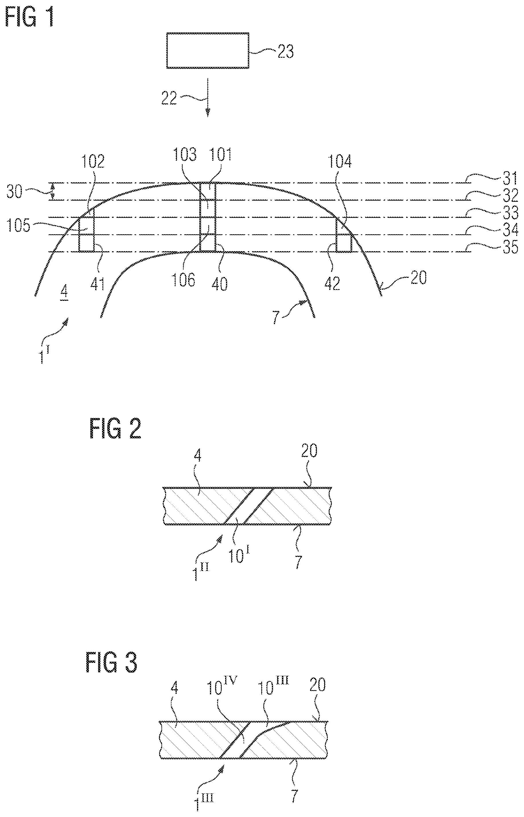
shows a first exemplary embodiment of a through-hole 10 ′ of a component 1 ″ comprising a substrate 4 .
The through-hole 10 ′ is advantageously constant in cross section, in particular cylindrical or oval-shaped, in the cross section of a through-flow direction of a cooling medium in the through-hole 10 ′ and can run at a certain angle to the outer surface 20 . In this case, for example, a cooling fluid flows out of the interior through the through-hole 10 ′ (e.g. film cooling hole). The inner cavity is bounded by the inner surface 7 .
shows a further through-hole 10 IV , which in addition to has a diffuser 10 ′″, which represents a widening of the hole in the region of the surface 20 , which, here too, can be curved as in .
The curvature of the surface 20 or any layers present (metallic layer, TBC) are not illustrated here.
schematically illustrates the procedure according to the invention which is applied to curved surfaces 20 of a component 1 ′, 1 ″, 1 ′″ with or without coatings (TBC).
A plurality of holes 40 , 41 , 42 , . . . are to be produced simultaneously at different locations.
In a Z direction 22 and a beam direction of a laser 23 , planes 31 , 32 , 33 , 34 , 35 , . . . perpendicular thereto are defined.
The first plane 31 represents, in particular, a secant to the surface 20 and advantageously, but not necessarily, touches a first hole 40 , which, however, is in any case closest to the laser 23 in the Z direction 22 . This is due to curvature and could be used to define “curvature”.
The laser 23 advantageously operates at a certain distance from the machined component, in this case, in particular, the focal position, i.e. the planes 31 , 32 , . . . .
In order to allow faster machining, the procedure according to the invention also depends on the focal position, which is taken here as the illustrative clearance of the laser.
The first plane 31 thus represents the first focal position, in which material is removed.
Thus, a first layer 101 of the first hole 40 to be produced is removed first. Another layer of another hole 41 , 42 does not lie in the plane 31 of the current focal position, for example.
A second plane 32 is then reached. Below this plane 32 in the thickness 30 of a region to be removed (=layer), two holes 40 , 41 are now included, namely a second layer 103 below the first layer 101 of the first hole 40 and a first layer 102 , here an outermost region, of a second hole 41 . The removed second layer 103 of the first hole 40 extends over the entire thickness 30 below the second plane 32 whereas the removed first layer 102 of the second hole 41 extends over less than the thickness 30 below the second plane 32 . These layers 102 , 103 are then removed next, wherein the first layer 102 of the second hole 41 is advantageously removed first after the first layer 101 for the first hole 40 has been removed and then advantageously the second layer 103 of the first hole 40 is removed.
In the next step, the shifted focal position of the laser 23 encompasses the plane 33 , a second layer 105 of the second hole 41 , as well as a third layer 106 of the first hole 40 and a first layer 104 of the third hole 42 , which is machined for the first time after the focal position has advanced.
Since the first hole 40 was advantageously machined last in the previous step, a first partial layer 104 of the third hole 42 and a second layer 105 of the second hole 41 are machined first, and then the third layer 106 of the hole 40 is machined as the next step for this removal plane.
In particular, the shifting of the focal position can take place continuously and, in particular, steadily.
In this way, the procedure is illustrated schematically up to the end, that is to say, in particular, up to the breakthrough for through-holes.
At the beginning, not all the holes 40 , 41 , 42 , . . . are encompassed by a focal position.
Likewise, close to the end of the production process, some holes 40 have already been completed, while other holes 41 , 42 still require further machining for completion.
Further modifications are easily recognizable for a person skilled in the art.
Of course, the holes 40 , 41 , 42 can also extend at a different angle to the surface 20 than illustrated in .
The average power of the laser 23 is advantageously 100 watts to 200 watts.
The laser is advantageously pulsed, wherein, in particular, nanosecond pulses, in particular ≤500 ns, are used.
Figures (1)
Citations
This patent cites (12)
- US2003/0127438
- US2006/0278613
- US2011/0185572
- US2013/0029093
- US2016/0031049
- US2016/0199945
- US10063309
- US102011000144
- US102014220525
- US2006069822
- US2013079246
- US2016055349