Abstract
A non-fixed shoulder brace is provided comprising: an affected shoulder support which is supported on an affected shoulder of a wearer; a waist support coupled to the wearer's waist; an affected arm mounting part in which the wearer's affected arm is inserted and which is supported by means of an affected shoulder strap member from the affected shoulder support; and an affected upper limb exercise assistance apparatus coupled to both ends of the waist support and disposed between the wearer's waist and the affected arm mounting part.
Claims (7)
1. A non-fixed shoulder brace comprising: an affected shoulder support configured to be supported on an affected shoulder of a wearer; a waist support configured to be coupled to the wearer's waist; an affected arm mounting part configured to receive an arm of an affected upper limb of the wearer, and that is supported by an affected shoulder strap member from the affected shoulder support; a normal arm mounting part configured to receive an arm of the wearer's normal upper limb; and an affected upper limb exercise assistance apparatus coupled to both ends of the waist support and configured to be disposed between the wearer's waist and the affected arm mounting part, wherein the affected upper limb exercise assistance apparatus assists movement of the affected arm mounting part and comprises: a first cable connected to a front of the affected arm mounting part; a second cable connected to a rear of the affected arm mounting part; a motor unit having the first cable and the second cable wound thereon and being configured to tension the first cable and the second cable; a control unit configured to control a driving force and a rotation direction of the motor unit; and a power unit configured to supply power to the motor unit and the control unit; and wherein the normal arm mounting part includes a first inertia sensor, and the control unit is configured to extract a walk cycle of the wearer from a signal received from the first inertia sensor and is configured to correct the driving force and the rotation direction of the motor unit in accordance with the walk cycle.
Show 6 dependent claims
2. The non-fixed shoulder brace of claim 1 , wherein the affected upper limb exercise assistance apparatus comprises a first friction reduction pad disposed to face the affected arm mounting part, and the affected arm mounting part comprises a second friction reduction pad disposed to face the wearer's waist.
3. The non-fixed shoulder brace of claim 2 , wherein the first and second friction reduction pads are made of friction minimizing material.
4. The non-fixed shoulder brace of claim 1 , wherein the affected arm mounting part comprises: a tension sensor and a second inertia sensor that is configured to measure a subluxation degree of the affected upper limb; and an electric stimulator that is configured to apply electrical stimulation to muscles of the affected upper limb according to the walk cycle of the wearer and the subluxation degree of the affected arm.
5. The non-fixed shoulder brace of claim 1 , wherein the affected upper limb exercise assistance apparatus uses pneumatic artificial muscles.
6. The non-fixed shoulder brace of claim 1 , wherein the waist support and the affected shoulder support are connected through a plurality of suspending shoulder strap members.
7. The non-fixed shoulder brace of claim 1 , wherein the affected upper limb exercise assistance apparatus comprises an elastic support disposed to face the wearer's waist.
Full Description
Show full text →
TECHNICAL FIELD
The present application relates to a non-fixed shoulder brace and, more particularly, to a shoulder brace that may prevent contracture of shoulder joint and elbow joint of an affected shoulder by inducing movement of an affected arm through an affected upper limb exercise assistance apparatus.
NATIONAL R&D PROJECT FOR SUPPORTING INVENTION
•
• Subject No.: 2016R1A5A1938472 • Name of Department: Ministry of Science and ICT • R&D Agency: National Research Foundation of Korea • Project Name: Basic Research Program Advanced Research Center Support Program (ERC) by Ministry of Science and ICT • Subject Name: Center for SoFT meta-Human • Contribution Ratio: 1/1 • Management Agency: Seoul National University SNU R&DB Foundation • Research Period: Dec. 11, 2016-Dec. 31, 2022
BACKGROUND ART
Recovery of shoulder function after cerebral apoplexy is a precondition for using hands and is important for walking and performing daily activities.
As shown in , 81% of patients with cerebral apoplexy have subluxation of affected shoulder joint due to hemiplegia, and a prevalence of pain in a shoulder joint is 42 to 73%.
In order to prevent this situation, a fixed-type brace as shown in is generally clinically used at present for most patients with hemiplegia.
However, although it is important to prevent subluxation of a shoulder joint through a shoulder brace, there is a problem that contracture of the shoulder joint and elbow joint is caused and the contracture not only interferes with recovery of upper limb function but also causes pain in the shoulder joint.
For example, as shown in , a shoulder brace 100 having an arm support 200 adjusts the abduction angle of a shoulder through a shoulder support 400 and an arm protector 300 , but it also causes contracture of the shoulder joint and elbow joint, which interferes with recovery of the function of the upper arm and causes pain in the shoulder joint.
Accordingly, it is difficult to achieve both of two contradictory treatment targets of preventing subluxation of a shoulder joint as well as of reducing contracture and pain of the shoulder joint and elbow joint using an existing fixed-type shoulder joint brace, so there is a need for a new type of brace.
PRIOR ART LITERATURE
Patent Literature
• 1. Korean Patent No. 0883324
SUMMARY OF THE DISCLOSURE
In order to solve the problems of the related art described above, an objective of the present invention is to provide a shoulder brace that allows for movement of an affected arm.
In an aspect of the present application, provided is a shoulder brace that can maximize the rehabilitation effect of a wearer and also prevent contracture of joints by measuring movement of a normal arm according to walking of the wearer and inducing a corresponding movement of an affected arm.
In another aspect of the present application, provided is a shoulder brace that can maximize the rehabilitation effect of a wearer and prevent contracture of joints by maintaining a pivot motion of a normal arm while preventing subluxation of an affected arm joint.
According to an aspect, in order to achieve the objectives, in exemplary embodiments of the present application, a non-fixed shoulder brace of the present application includes: an affected shoulder support which is supported on an affected shoulder of a wearer; a waist support coupled to the wearer's waist; an affected arm mounting part in which an arm of an affected upper limb of the wearer is inserted and that is supported by an affected shoulder strap member from the affected shoulder support; and an affected upper limb exercise assistance apparatus coupled to both ends of the waist support and disposed between the wearer's waist and the affected arm mounting part, in which the affected upper limb exercise assistance apparatus assists movement of the affected arm mounting part.
In an embodiment, the affected upper limb exercise assistance apparatus of the present application may include: a first cable connected to a front of the affected arm mounting part; a second cable connected to a rear of the affected arm mounting part; a motor unit having the first cable and the second cable wound thereon and tensioning the first cable and the second cable; a control unit controlling driving force and rotation direction of the motor unit; and a power unit supplying power to the motor unit and the control unit.
In an embodiment, the affected upper limb exercise assistance apparatus may be manufactured to have a type of moving an affected arm of a wearer by pulling a cable using an electric motor and a type of using pneumatic artificial muscles.
In an embodiment, the non-fixed shoulder brace of the present application may further include a normal arm mounting part in which an arm of the wearer's normal upper limb is inserted, in which the normal arm mounting part may include a first inertia sensor, and the control unit may extract a walk cycle of a wearer from a signal received from the first inertia sensor and may correct the driving force and the rotation direction of the motor unit in accordance with the walk cycle.
In an embodiment, the affected arm mounting part of the present application may include: a tension sensor and a second inertia sensor that measure a degree of subluxation of an affected upper limb; and an electric stimulator that applies electrical stimulation to muscles of the affected upper limb in accordance with the walk cycle of the wearer and the degree of subluxation of the affected arm.
In an embodiment, the waist support and the affected shoulder support of the present application may be connected through a plurality of suspending shoulder strap members.
In an embodiment, the affected upper limb exercise assistance apparatus of the present application may include an elastic support disposed to face the waist of the wearer.
In an embodiment, the affected upper limb exercise assistance apparatus of the present application may include a first friction reduction pad disposed to face the affected arm mounting part, and the affected arm mounting part may include a second friction reduction pad disposed to face the waist of the wearer.
In an embodiment, the first and second friction reduction pads may be made of Teflon.
According to another aspect, in order to achieve the objectives, in exemplary embodiments of the present application, a non-fixed shoulder brace of the present application includes: an affected shoulder support which is supported on an affected shoulder of a wearer; a waist support coupled to the waist of the wearer; an affected arm mounting part in which an arm of an affected upper limb of the wearer is inserted and that is supported by an affected shoulder strap member from the affected shoulder support; a normal arm mounting part in which an arm of a normal upper limb of the wearer is inserted; and an affected upper limb exercise assistance apparatus coupled to both ends of the waist support and disposed between the waist of the wearer and the affected arm mounting part.
In an embodiment, the affected upper limb exercise assistance apparatus may include a belt connecting the affected arm mounting part and the normal arm mounting part and a plurality of belt insertion holes through which the belt is inserted.
In an embodiment, the waist support and the affected shoulder support of the present application may be connected through a plurality of suspending shoulder strap members.
In an embodiment, the affected upper limb exercise assistance apparatus of the present application may include an elastic support disposed to face the waist of the wearer.
In an embodiment, the affected upper limb exercise assistance apparatus of the present application may include a first friction reduction pad disposed to face the affected arm mounting part, and the affected arm mounting part may include a second friction reduction pad disposed to face the waist of the wearer.
In an embodiment, an inner side of the affected upper limb exercise assistance apparatus of the present application may be formed to be fitted to the curve of the waist of the wearer, and the upper half of the upper side thereof may be narrow and curved in comparison to the lower half to be fitted to the curve of the armpit of the wearer.
In an embodiment, the outer side of the affected upper limb exercise assistance apparatus of the present application may be made of a hard material for inducing movement of the affected arm of the wearer when the wearer walks.
In an embodiment, the first and second friction reduction pads may be made of Teflon.
In an embodiment, the affected upper limb exercise assistance apparatus may assist a wearer to move forward the normal arm mounting part by pivoting forward the normal arm and may assist the affected arm mounting part to pivot rearward the affected arm of the wearer in response to movement of the normal arm mounting part.
According to the present invention, it is possible to prevent subluxation of the affected shoulder joint while reducing contracture and pain by inducing movement of the affected arm from movement of a normal arm.
BRIEF DESCRIPTION OF DRAWINGS
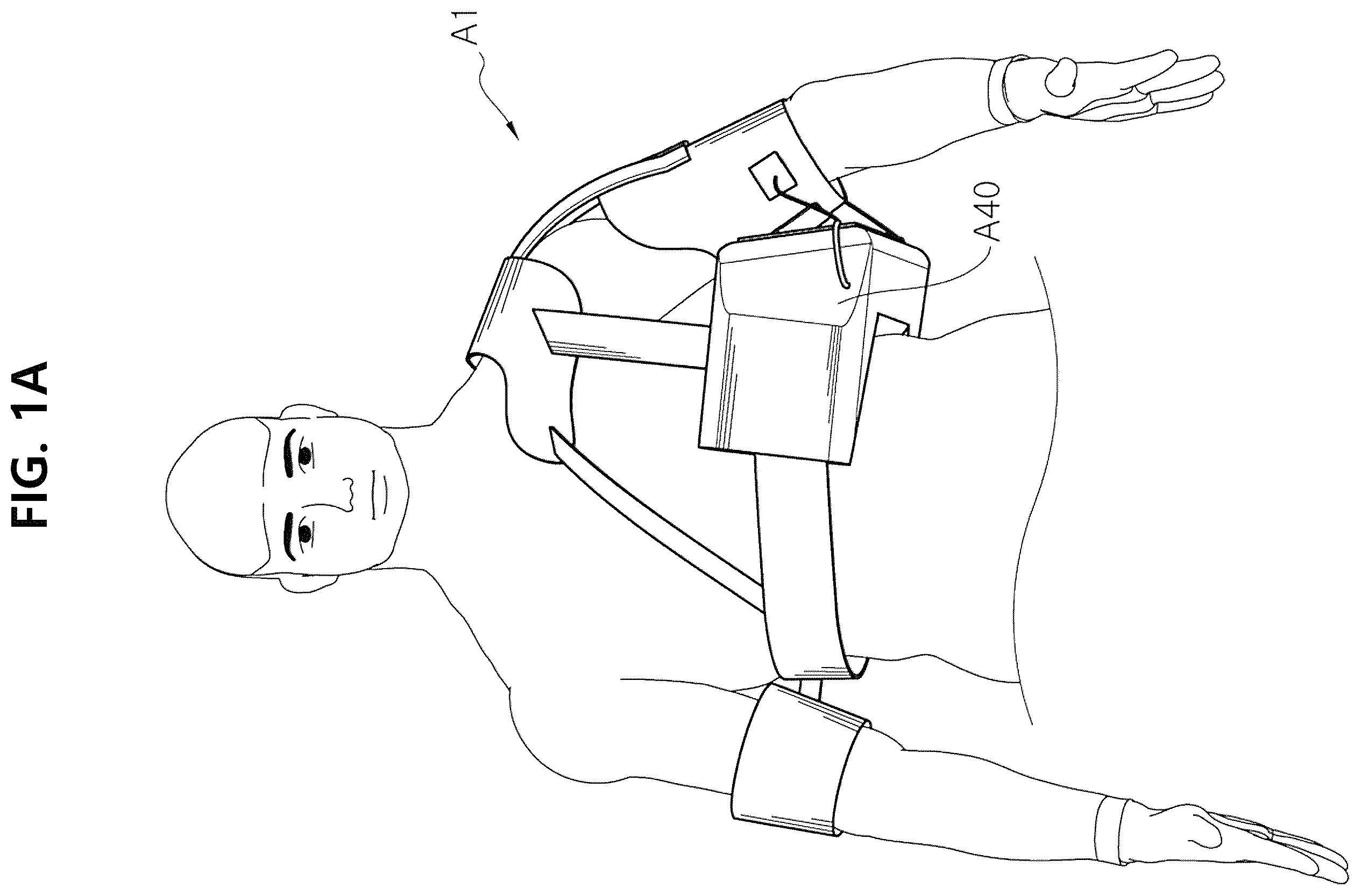
A and 1 B are perspective views schematically showing a front and a back of a user wearing a non-fixed shoulder brace according to a first embodiment of the present application.
is a perspective view schematically showing components of the non-fixed shoulder brace according to the first embodiment of the present application.
is a perspective view schematically showing connection relationships between components of an affected upper limb exercise assistance apparatus and an affected arm mounting part according to the first embodiment of the present application.
is a cross-sectional view schematically showing an inside of the affected upper limb exercise assistance apparatus according to the first embodiment of the present application.
is a view schematically showing movement of an affected arm of a user wearing the non-fixed shoulder brace according to the first embodiment of the present application.
A and 6 B are perspective views schematically showing a front and a back of a user wearing a non-fixed shoulder brace according to a second embodiment of the present application.
is a perspective view schematically showing components of the non-fixed shoulder brace according to the second embodiment of the present application.
is a perspective view schematically showing components of an affected upper limb exercise assistance apparatus according to the second embodiment of the present application.
is a view schematically showing movement of an affected arm and a normal arm of a user wearing the non-fixed shoulder brace according to the second embodiment of the present application.
is a picture and a view showing subluxation of a shoulder joint after cerebral apoplexy.
is a picture showing a fixed-type shoulder brace for preventing subluxation of a shoulder joint.
is a view schematically showing a conventional fixed-type shoulder brace according to the prior art.
DESCRIPTION OF REFERENCE NUMBERS
•
• A 1 : non-fixed shoulder brace A 11 : affected shoulder support • A 11 a : tension sensor A 12 : suspending shoulder strap member • A 13 : waist support A 14 : apparatus support • A 15 : affected shoulder strap • A 21 : affected arm mounting part A 22 a : second inertia sensor • A 22 : electric stimulator A 23 : second friction reduction pad • A 32 : first inertia sensor A 40 : affected arm assistant • A 41 : elastic support A 42 a : first cable • A 42 b : second cable A 43 : first friction reduction pad • A 44 : motor unit A 45 : control unit • A 46 : power unit • P 1 : non-fixed shoulder brace P 11 : affected shoulder support • P 12 : suspending shoulder strap member P 13 : waist support • P 15 : affected shoulder strap • P 21 : affected arm mounting part • P 22 : affected arm mounting part connection portion • P 23 : second friction reduction pad P 31 : normal arm mounting part • P 32 : normal arm mounting part connection portion • P 40 : affected upper limb exercise assistance apparatus • P 41 : belt P 42 : belt insertion hole • P 43 : first friction reduction pad P 45 : elastic support
DETAILED DESCRIPTION
Hereafter, a non-fixed shoulder brace according to an embodiment of the present application is described through preferred embodiments of the present application with reference to the accompanying drawings.
In various embodiments, components having the same configuration are given the same reference numerals and are representatively described in an embodiment, and only different components are described in other embodiments.
A and 1 B are perspective views schematically showing a front and a back of a user wearing a non-fixed shoulder brace A 1 according to a first embodiment of the present application.
As shown in A and 1 B , a non-fixed shoulder brace A 1 according to a first embodiment of the present application is designed to be worn on the upper body of a wearer; particularly, an affected upper limb exercise assistance apparatus A 40 is held on a waist of the wearer by a waist support A 13 and positioned between the wearer's waist and affected arm. Here the detailed components of the affected upper limb exercise assistance apparatus A 40 will be described below.
is a perspective view schematically showing components of the non-fixed shoulder brace A 1 according to the first embodiment of the present application.
As shown in , the non-fixed shoulder brace A 1 according to the first embodiment of the present application includes an affected shoulder support A 11 , a waist support A 13 , an affected arm mounting part A 21 , and an affected upper limb exercise assistance apparatus A 40 .
In detail, the affected shoulder support A 11 is supported on an affected shoulder of a wearer and the waist support A 13 is coupled to the wearer's waist.
The affected arm mounting part A 21 is coupled together with an arm of an affected upper limb of the wearer with the arm of the affected upper limb inserted therein.
In particular, the affected shoulder support A 11 and the affected arm mounting part A 21 are connected through an affected shoulder strap A 15 and the affected arm mounting part A 21 is pulled towards inside the wearer's shoulder, whereby it is possible to prevent dislocation of the wearer's affected shoulder.
The waist support A 13 and the affected shoulder support A 11 are connected through a plurality of suspending shoulder strap members A 12 , so it is possible to reduce a load of the affected arm, which is applied to the affected shoulder support A 11 , to the waist support A 13 .
The affected arm assistant A 40 may reduce its load through an apparatus support A 14 .
is a perspective view schematically showing connection relationships between components of an affected upper limb exercise assistance apparatus A 40 and an affected arm mounting part A 21 according to the first embodiment of the present invention.
As shown in , the affected upper limb exercise assistance apparatus A 40 is coupled to the affected arm mounting part through a first cable A 42 a connected to a front of the affected arm mounting part A 21 and a second cable A 42 b connected to a rear of the affected arm mounting part A 21 .
The affected upper limb exercise assistance apparatus A 40 may be coupled to both ends of the waist support A 13 and held on the wearer's waist.
In detail, a curved groove is formed on a side of the affected upper limb exercise assistance apparatus so that it may be easily fitted to the wearer's waist, and a portion where the curved groove is formed is made by an elastic support A 41 so that a shape of the affected upper limb exercise assistance apparatus A 40 may be easily deformed to be fitted to a waist shape of the wearer.
As shown in , the affected upper limb exercise assistance apparatus A 40 includes a first friction reduction pad A 43 disposed on a side thereof facing the affected arm mounting part A 21 . The affected arm mounting part A 21 also has a second friction reduction pad A 23 disposed on a side thereof facing the wearer's waist.
Accordingly, friction between the affected arm mounting part A 21 and the affected upper limb exercise assistance apparatus A 40 may be reduced while the wearer's affected arm is moved, so it is possible to reduce resistance that interferes with movement of the affected arm mounting part A 21 by the wearer.
In particular, the first friction reduction pad A 43 and the second friction reduction pad A 23 are made of Teflon, whereby friction can be minimized.
The normal arm mounting part A 31 includes a first inertia sensor A 32 , and a program of a control unit A 45 included in the affected upper limb exercise assistance apparatus A 40 may extract a walk cycle of the wearer from a signal received from the first inertia sensor A 32 .
As shown in , the non-fixed shoulder brace A 1 that is the first embodiment of the present invention may improve mobility of an affected arm through electric stimulation by measuring subluxation degree of the wearer.
In detail, the affected shoulder support A 11 may include a tension sensor A 11 a and the affected arm mounting part A 21 may include a second inertia sensor A 22 a . Signals extracted from the tension sensor A 11 a and the second inertia sensor A 22 a may extract information about the walk cycle and the subluxation degree of the wearer from the program of the control unit A 45 included in the affected upper limb exercise assistance apparatus A 40 . This information signal applies an electrical signal to an electric stimulator A 22 of the affected arm mounting part A 21 worn on an affected upper limb of the wearer, whereby electric stimulation may be applied to muscles of the wearer's affected upper limb.
is a cross-sectional view schematically showing an inside of the affected upper limb exercise assistance apparatus A 40 according to the first embodiment of the present invention.
As shown in , the affected upper limb exercise assistance apparatus A 40 includes a motor unit A 44 on which the first cable A 42 a and the second cable A 42 b are wound, a control unit A 45 that may control driving force and rotation direction of the motor unit A 44 , and a power unit A 46 that supplies power to the motor unit A 44 and the control unit A 45 .
In particular, the first cable A 42 a and the second cable A 42 b may be tensioned toward the motor unit A 44 in accordance with the driving force applied to the motor unit A 44 . That is, when the first cable A 42 a is wound to be tensioned, the second cable A 42 b is unwound from the motor unit 44 . Further, when the second cable A 42 b is wound to be tensioned, the first cable A 42 a is unwound from the motor unit A 44 .
Accordingly, since one motor unit A 44 is driven in two directions and the first cable A 42 a and the second cable A 42 b may be separately tensioned, it is possible to simplify a design of the affected upper limb exercise assistance apparatus A 40 and as well remarkably reduce space for the entire affected upper limb exercise assistance apparatus A 40 .
Further, the control unit A 45 may control the driving force and rotation direction of the motor unit A 44 and may correct the driving force and rotation direction of the motor unit A 44 in accordance with the walk cycle of the wearer extracted from a signal from the first inertia sensor A 32 .
Further, the control unit A 45 may also include a program that may control the intensity and cycle of electric stimulation that is applied to the electric stimulator A 22 on the basis of the information about the walk cycle and the subluxation degree of the wearer extracted from the tension sensor A 11 a and the second inertia sensor A 22 a.
As for the power unit A 46 that supplies power to the motor unit A 44 and the control unit A 45 , for example, a chargeable battery may be used, and the affected upper limb exercise assistance apparatus A 40 may be operated by a battery without being connected to an external power, so portability of the shoulder brace may be considerably improved.
is a view schematically showing movement of an affected arm of a user wearing the non-fixed shoulder brace A 1 according to the first embodiment of the present invention. As described above, the first cable A 42 a and the second cable A 42 b that are tensioned in opposite directions are connected to the affected arm mounting part A 21 , so an affected arm of the wearer may be moved forward or backward by moving any one of the cables.
In detail, as shown in (a) of , when the timing at which the wearer moves rearward an affected arm in accordance with the walk cycle is reached, the motor unit A 44 is driven in response thereto so that the second cable A 42 b tensions the affected arm mounting part A 21 , whereby the affected arm is moved rearward.
Further, as shown in (b) of , when the timing at which the wearer moves forward an affected arm in accordance with the walk cycle is reached, the motor unit A 44 is driven in response thereto so that the first cable A 42 a tensions the affected arm mounting part A 21 , whereby the affected arm is moved forward.
Accordingly, since the affected upper limb exercise assistance apparatus A 40 may automatically assist an affected arm to move forward and rearward in accordance with the walk cycle of the wearer, it is possible to prevent pain due to contracture of the affected shoulder joint and elbow joint of the wearer.
A and 6 B are perspective views schematically showing a front and a back of a user wearing a non-fixed shoulder brace P 1 according to a second embodiment of the present invention.
As shown in A and 6 B , a non-fixed shoulder brace P 1 according to the second embodiment of the present invention is designed to be worn on an upper body of a wearer; particularly, an affected upper limb exercise assistance apparatus P 40 is held on the wearer's waist by a waist support P 13 and positioned between the wearer's waist and affected arm.
The detailed components of the affected upper limb exercise assistance apparatus P 40 will be described below.
is a perspective view schematically showing components of the non-fixed shoulder brace P 1 according to the second embodiment of the present invention.
As shown in , the non-fixed shoulder brace P 1 according to the second embodiment of the present invention includes an affected shoulder support P 11 , a waist support P 13 , an affected arm mounting part P 21 , a normal arm mounting part P 31 , and an affected upper limb exercise assistance apparatus P 40 .
In detail, the affected shoulder support P 11 is supported on an affected shoulder of the wearer, and the waist support P 13 is coupled to the wearer's waist.
The affected arm mounting part P 21 and the normal arm mounting part P 31 are coupled together with an arm of the affected upper limb and an arm of the normal upper limb with the arms inserted therein, respectively.
In particular, the affected shoulder support P 11 and the affected arm mounting part P 21 are connected through an affected shoulder strap P 15 and the affected arm mounting part P 21 is pulled towards inside the wearer's shoulder, whereby it is possible to prevent dislocation of the wearer's affected shoulder.
Further, the waist support P 13 and the affected shoulder support P 11 are connected through a plurality of suspending shoulder strap members P 12 , so it is possible to reduce a load of the affected arm, which is applied to the affected shoulder support P 11 , to the waist support P 13 .
is a perspective view schematically showing components of an affected upper limb exercise assistance apparatus P 40 according to the second embodiment of the present invention.
As shown in , the affected upper limb exercise assistance apparatus P 40 is coupled to both ends P 44 of the waist support P 13 , so it may be held on the wearer's waist.
In detail, a curved groove is formed on a side of the affected upper limb exercise assistance apparatus so that it may be easily fitted to the wearer's waist, and a portion where the curved groove is formed is made by an elastic support P 45 so that a shape of the affected upper limb exercise assistance apparatus may be easily deformed to be fitted to a waist shape of the wearer.
Further, as shown in , the affected arm mounting part P 21 and the normal arm mounting part P 31 are connected to each other at connection portions P 22 and P 32 , respectively, through a belt P 41 . The belt P 41 is disposed through a plurality of insertion holes P 42 formed on a side of the body of the affected upper limb exercise assistance apparatus P 40 , whereby it is possible to guide movement of the belt P 41 and prevent the belt P 41 from sagging down due to its own weight.
Meanwhile, the affected upper limb exercise assistance apparatus P 40 includes a first friction reduction pad P 43 disposed on a side thereof facing the affected arm mounting part P 21 . The affected arm mounting part P 21 also has a second friction reduction pad P 23 disposed on a side thereof facing the wearer's waist.
Accordingly, friction between the affected arm mounting part P 21 and the affected upper limb exercise assistance apparatus P 40 may be reduced while the wearer's affected arm is moved, so it is possible to reduce resistance that interferes with movement of the affected arm mounting part P 21 by the wearer.
In particular, the first friction reduction pad P 43 and the second friction reduction pad P 23 are made of Teflon, whereby friction can be minimized.
An inner side of the affected upper limb exercise assistance apparatus of the present invention may be made to be fitted to a curve of the wearer's waist, and an upper half of an upper side of the affected upper limb exercise assistance apparatus is narrow and made to have curved groove in comparison to a lower half of the upper side so that the upper side is fitted to a curve of an armpit of the wearer.
is a view schematically showing movement of an affected arm and a normal arm of a user wearing the non-fixed shoulder brace P 1 according to the second embodiment of the present application.
As described above, since the affected arm mounting part P 21 and the normal arm mounting part P 31 are connected to each other through the belt P 41 , movement of any one arm may assist movement of the other arm.
In detail, as shown in (a) of , when a wearer pivots forward a normal arm, the normal arm mounting part P 31 is correspondingly moved forward. Since the affected arm mounting part P 21 is connected to the normal arm mounting part P 31 through the belt P 41 , the affected arm of the wearer is pivoted rearward in response to the movement of the normal arm mounting part P 31 .
Further, as shown in (b) of , when a wearer pivots forward an affected arm, the affected arm mounting part P 21 is correspondingly moved forward. Since the normal arm mounting part P 31 is connected to the affected arm mounting part P 21 through the belt P 41 , the normal arm of the wearer is pivoted rearward in response to the movement of the affected arm mounting part P 21 .
Therefore, when the normal arm is moved forward and rearward in accordance with the wearer's walk, the affected arm may also be moved forward and rearward in response to the movement of the normal arm, so it is possible to prevent pain due to contracture of the affected shoulder joint and the elbow joint of the wearer.
Those skilled in the art may understand, with reference to be above description, that the present invention may be achieved in other embodied ways without a change of the spirit or the necessary features of the present invention.
Therefore, it should be understood that the embodiments described above are not limitative but only exemplary in all respects, the scope of the present invention is expressed by claims described below, not the detailed description, and it should be construed that all changes and modifications achieved from the meanings, the scope and equivalent concepts of the claims are included in the scope of the present invention.
The non-fixed shoulder brace according to exemplary embodiments of the present application may prevent subluxation of the affected shoulder joint while reducing contracture and pain by inducing movement of an affected arm through an affected upper limb exercise assistance apparatus.
Figures (14)
Citations
This patent cites (27)
- US3892230
- US4198964
- US4441707
- US5188587
- US5203763
- US5590420
- US8016780
- US2006/0211956
- US2010/0160842
- US2012/0101419
- US2016/0000635
- US2018/0028274
- US2018/0116893
- US2020/0038218
- US2467974
- US2002-177310
- US2012011102
- US2014-128464
- US10-0883324
- US10-2010-0097070
- US20-0465621
- US10-2015-0120084
- US20150120084
- US10-1861041
- US10-2019-0065271
- US20190124651
- US2018065459