Abstract
A multiband antenna is connected to a host conductor when used. The multiband antenna extends long in a first direction. The multiband antenna has a conductor main portion and a ground terminal. The conductor main portion extends in a horizontal plane which is defined by the first direction and a second direction perpendicular to the first direction. The conductor main portion is formed with an opening and a slot. The slot extends long in the first direction. The conductor main portion has a first short edge, a second short edge, a first long edge and a second long edge. The ground terminal is connected to the host conductor when the multiband antenna is used. The ground terminal extends from the second long edge. The ground terminal is positioned closer to the first short edge than to the second short edge in the first direction.
Claims (10)
1. A multiband antenna which is connected to a host conductor when used, a direction along which a longest side of the multiband antenna extends corresponding to a first direction, and the multiband antenna comprising: a conductor main portion; a ground terminal; a feed point; and a radiation element, wherein: the conductor main portion extends in a horizontal plane which is defined by the first direction and a second direction perpendicular to the first direction; an opening and a slot are provided in the conductor main portion; a long side of the slot extends in the first direction; the conductor main portion has a first short edge, a second short edge, a first long edge, and a second long edge; the first short edge and the second short edge are positioned at respective opposite ends of the conductor main portion in the first direction; the first long edge and the second long edge are positioned at respective opposite ends of the conductor main portion in the second direction; the opening is provided at the first short edge and connects the slot with an outside of the conductor main portion in the first direction; the ground terminal is connected to the host conductor when the multiband antenna is used; the ground terminal extends from the second long edge; the ground terminal is positioned closer to the first short edge than to the second short edge in the first direction; the feed point is positioned closer to the second short edge than to the first short edge in the first direction; the radiation element has a first portion and a second portion; the first portion extends from the conductor main portion so as to be apart from the slot in the second direction; the first portion has a first length in the second direction; the second portion extends in the first direction from the first portion; the second portion has a second length in the first direction; the second length is greater than the first length; and the first portion is positioned closer to the first short edge than to the second short edge in the first direction.
Show 9 dependent claims
2. The multiband antenna as recited in claim 1 , wherein the ground terminal extends so as to be, at least in part, continuous with the first short edge.
3. The multiband antenna as recited in claim 1 , wherein: the radiation element further has a folded portion; and the folded portion extends from the second portion in a direction which intersects with the horizontal plane.
4. The multiband antenna as recited in claim 3 , wherein: the radiation element further has an additional extending portion; and the additional extending portion extends from the folded portion in a direction which intersects with the folded portion.
5. The multiband antenna as recited in claim 1 , wherein: the multiband antenna further comprises a stub; the conductor main portion has a connection portion and an opposed portion; the connection portion and the opposed portion are positioned so that the slot is between the connection portion and the opposed portion in the second direction; the stub has a first end and a second end in the second direction; the first end of the stub is connected with the connection portion; and the second end of the stub is spaced apart from the opposed portion and faces the opposed portion.
6. The multiband antenna as recited in claim 1 , wherein the ground terminal has a part extending in a direction which intersects with the horizontal plane.
7. The multiband antenna as recited in claim 6 , wherein: the multiband antenna further has a feed terminal; and the feed terminal has a part extending in a direction which intersects with the horizontal plane.
8. The multiband antenna as recited in claim 7 , wherein: the multiband antenna is configured so that at least the conductor main portion and the feed terminal are made of a metal plate; the feed terminal has a protruding portion and a junction; the protruding portion protrudes in the slot from an inner edge of the slot; the protruding portion has an end in the first direction; and the junction extends from the end of the protruding portion in a direction which intersects with the horizontal plane.
9. The multiband antenna as recited in claim 1 , wherein: the multiband antenna further has an extending portion; and the extending portion extends from the conductor main portion in a direction which intersects with the horizontal plane.
10. The multiband antenna as recited in claim 1 , wherein the radiation element works as an unpowered antenna.
Full Description
Show full text →
CROSS REFERENCE TO RELATED APPLICATIONS
This application is based on and claims priority under 35 U.S.C. § 119 to Japanese Patent Application No. JP2021-084571 filed May 19, 2021, the contents of which are incorporated herein in their entirety by reference.
BACKGROUND OF THE INVENTION
This invention relates to a multiband antenna which is connected to a host conductor when used.
Referring to , a multiband antenna 900 of JPA2012-85262 (Patent Document 1) comprises a conductive plate 910 , or a conductor main portion 910 . The conductor main portion 910 is formed with two openings 912 and two slots 914 . Each of the slots 914 extends long in a Y-direction.
A multiband antenna such as the multiband antenna of Patent Document 1 is required to provide good antenna characteristics and to be further downsized.
SUMMARY OF THE INVENTION
It is therefore an object of the present invention to provide a multiband antenna which provides good antenna characteristics and can be further downsized.
One aspect of the present invention provides a multiband antenna which is connected to a host conductor when used. The multiband antenna extends long in a first direction. The multiband antenna has a conductor main portion and a ground terminal. The conductor main portion extends in a horizontal plane which is defined by the first direction and a second direction perpendicular to the first direction. The conductor main portion is formed with an opening and a slot. The slot extends long in the first direction. The conductor main portion has a first short edge, a second short edge, a first long edge and a second long edge. The first short edge and the second short edge are positioned at opposite ends, respectively, of the conductor main portion in the first direction. The first long edge and the second long edge are positioned at opposite ends, respectively, of the conductor main portion in the second direction. The opening is formed at the first short edge and connects the slot with an outside of the conductor main portion in the first direction. The ground terminal is connected to the host conductor when the multiband antenna is used. The ground terminal extends from the second long edge. The ground terminal is positioned closer to the first short edge than to the second short edge in the first direction.
In the multiband antenna of the present invention, the ground terminal is connected to the host conductor when the multiband antenna is used. Thus, the multiband antenna of the present invention alone can be downsized by utilizing the host conductor, which is an external component and is connected with the ground terminal, as a part of a multiband antenna.
In the multiband antenna of the present invention, the ground terminal extends from the second long edge. This enables the multiband antenna of the present invention to obtain high radiation efficiency.
In the multiband antenna of the present invention, the ground terminal is positioned closer to the first short edge than to the second short edge in the first direction. Thus, the multiband antenna of the present invention can have a low resonant frequency without upsizing the multiband antenna alone.
An appreciation of the objectives of the present invention and a more complete understanding of its structure may be had by studying the following description of the preferred embodiment and by referring to the accompanying drawings.
BRIEF DESCRIPTION OF THE DRAWINGS
is a top view showing a multiband antenna according to a first embodiment of the present invention. In the figure, a host conductor is illustrated by broken line.
is a top view showing a first modification of the multiband antenna of .
is a top view showing a second modification of the multiband antenna of .
is a top view showing a third modification of the multiband antenna of .
is a top view showing a fourth modification of the multiband antenna of .
is a perspective, schematic view showing a multiband antenna according to a second embodiment of the present invention.
is a perspective, schematic view showing a first modification of the multiband antenna of .
is a perspective, schematic view showing a second modification of the multiband antenna of .
is a perspective, schematic view showing a third modification of the multiband antenna of .
is a perspective, schematic view showing a fourth modification of the multiband antenna of .
is a perspective, schematic view showing a fifth modification of the multiband antenna of .
is a perspective, schematic view showing a sixth modification of the multiband antenna of .
is a perspective, schematic view showing a seventh modification of the multiband antenna of .
is a perspective, schematic view showing an eighth modification of the multiband antenna of .
is a perspective, schematic view showing a ninth modification of the multiband antenna of .
is a view showing a modification of a stub.
is a top view showing a multiband antenna of Patent Document 1.
While the invention is susceptible to various modifications and alternative forms, specific embodiments thereof are shown by way of example in the drawings and will herein be described in detail. It should be understood, however, that the drawings and detailed description thereto are not intended to limit the invention to the particular form disclosed, but on the contrary, the intention is to cover all modifications, equivalents and alternatives falling within the spirit and scope of the present invention as defined by the appended claims.
DETAILED DESCRIPTION
First Embodiment
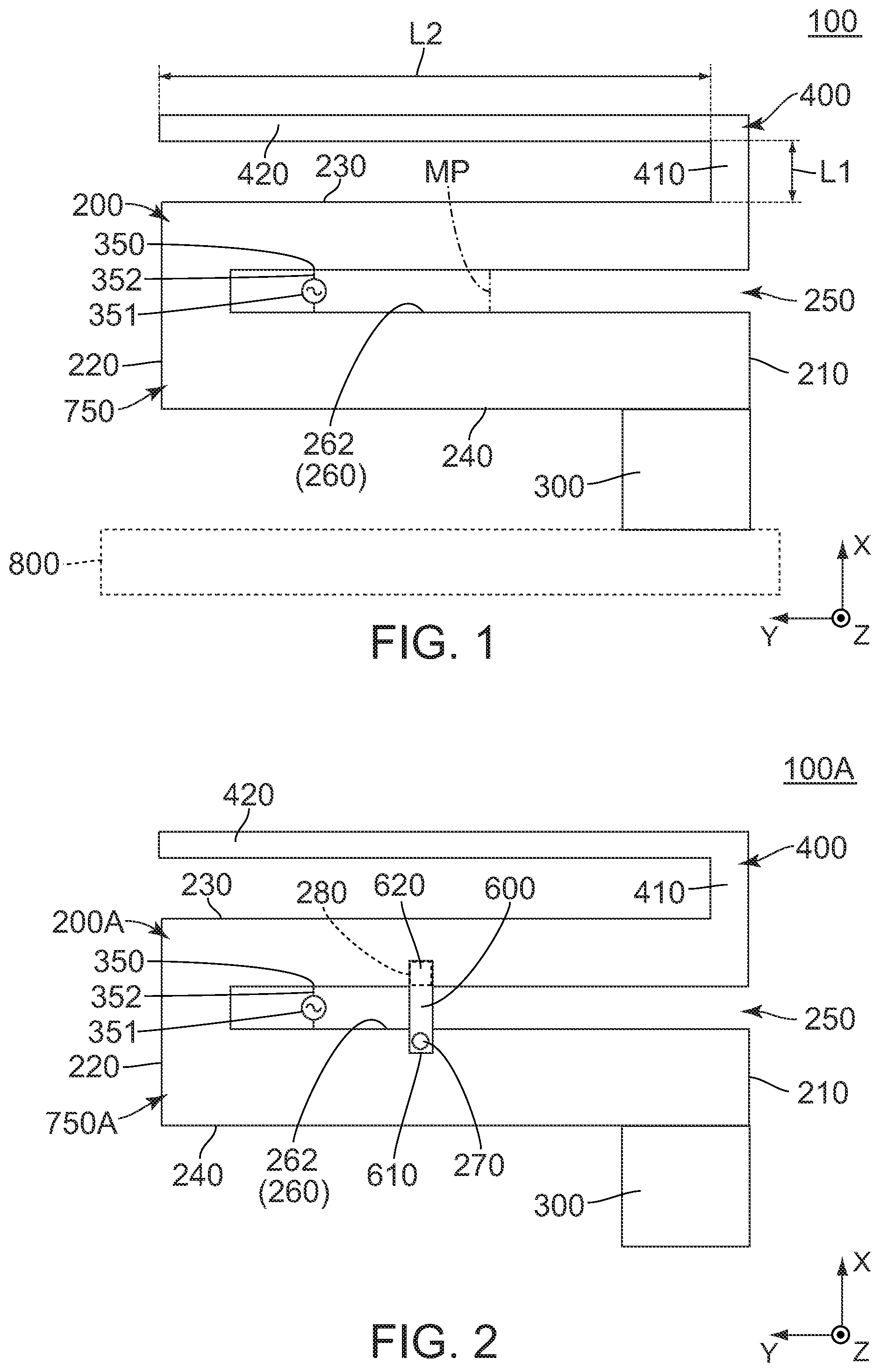
Referring to , a multiband antenna 100 according to a first embodiment of the present invention is partially made of a metal plate 750 . However, the present invention is not limited thereto. Specifically, the whole of the multiband antenna 100 may be made of the metal plate 750 . As shown in . the multiband antenna 100 of the present embodiment is connected to a host conductor 800 when used. In the present embodiment, the host conductor 800 is, for example, a metal housing of a device, in which the multiband antenna 100 is placed, or a ground trace on a printed circuit board, such as a motherboard, which is distinct and separated from the multiband antenna 100 .
Referring to , the multiband antenna 100 has a plurality of operating frequencies. The multiband antenna 100 extends long in a first direction. In the present embodiment, the first direction is a Y-direction. In addition, the first direction is also referred to as a right-left direction. Specifically, it is assumed that rightward is a positive Y-direction while leftward is a negative Y-direction.
As shown in , the multiband antenna 100 has a conductor main portion 200 and a ground terminal 300 . Referring to , the multiband antenna 100 has no supporting member which supports the conductor main portion 200 . However, the present invention is not limited thereto. Specifically, if the conductor main portion 200 has low strength because, for example, the conductor main portion 200 is thin, the multiband antenna 100 may have a supporting member which supports the conductor main portion 200 .
Referring to , the conductor main portion 200 of the present embodiment is made of the metal plate 750 . The conductor main portion 200 extends in a horizontal plane which is defined by the first direction and a second direction perpendicular to the first direction. In the present embodiment, the second direction is an X-direction. In addition, the second direction is also referred to as a front-rear direction. Specifically, it is assumed that forward is a positive X-direction while rearward is a negative X-direction. In other words, the conductor main portion 200 extends in the horizontal plane perpendicular to a perpendicular direction which is perpendicular to both the first direction and the second direction. In the present embodiment, the perpendicular direction is a Z-direction. Specifically, it is assumed that upward is a positive Z-direction while downward is a negative Z-direction. In addition, the horizontal plane of the present embodiment is an XY-plane.
As shown in , the conductor main portion 200 has a first short edge 210 , a second short edge 220 , a first long edge 230 and a second long edge 240 .
As shown in , each of the first short edge 210 and the second short edge 220 of the present embodiment extends in the second direction. Each of the first short edge 210 and the second short edge 220 has a linear shape. However, the present invention is not limited. The first short edge 210 may have a shape other than the linear shape, and the second short edge 220 may have a shape other than the linear shape. The first short edge 210 and the second short edge 220 are positioned at opposite ends, respectively, of the conductor main portion 200 in the first direction.
As shown in , each of the first long edge 230 and the second long edge 240 of the present embodiment extends in the first direction. Each of the first long edge 230 and the second long edge 240 has a linear shape. However, the present invention is not limited. The first long edge 230 may have a shape other than the linear shape, and the second long edge 240 may have a shape other than the linear shape. The first long edge 230 and the second long edge 240 are positioned at opposite ends, respectively, of the conductor main portion 200 in the second direction.
As shown in , the conductor main portion 200 is formed with an opening 250 and a slot 260 .
As shown in , the opening 250 of the present embodiment is formed at the first short edge 210 . The opening 250 connects the slot 260 with the outside of the conductor main portion 200 in the first direction.
As shown in , the slot 260 of the present embodiment extends long in the first direction. The slot 260 has an inner edge 262 .
Referring to , the ground terminal 300 of the present embodiment is a copper tape. However, the present embodiment is not limited thereto. Specifically, the ground terminal 300 may be made of the metal plate 750 . The ground terminal 300 is connected to the host conductor 800 when the multiband antenna 100 is used. The ground terminal 300 extends from the second long edge 240 . The ground terminal 300 is positioned closer to the first short edge 210 than to the second short edge 220 in the first direction. Specifically, the ground terminal 300 is positioned closer to the opening 250 than to a midpoint MP of the slot 260 in the first direction. More specifically, the ground terminal 300 extends so as to be continuous with the first short edge 210 . However, the present invention is not limited thereto. Specifically, the multiband antenna 100 should be configured so that the ground terminal 300 extends so as to be, at least in part, continuous with the first short edge 210 . This configuration enables the multiband antenna 100 to have a low resonant frequency. This also means that, if the multiband antenna 100 with this configuration and a multiband antenna without this configuration have the same resonant frequency, the multiband antenna 100 with this configuration has a size smaller than a size of the multiband antenna without this configuration.
As shown in , the multiband antenna 100 of the present embodiment further comprises a radiation element 400 . However, the present embodiment is not limited thereto. Specifically, the multiband antenna 100 may comprise no radiation element 400 .
Referring to , the radiation element 400 of the present embodiment is made of the metal plate 750 . An electrical length of the radiation element 400 is defined with reference to one-fourth of a wavelength of one of the operating frequencies of the multiband antenna 100 . In other words, the electrical length of the radiation element 400 corresponds to one-fourth of a wavelength of any one of the operating frequencies of the multiband antenna 100 . The radiation element 400 has a first portion 410 and a second portion 420 .
As shown in , the first portion 410 of the present embodiment extends from the conductor main portion 200 so as to be apart from the slot 260 in the second direction. More specifically, the first portion 410 extends forward from the first long edge 230 of the conductor main portion 200 in the front-rear direction. The first portion 410 has a flat-plate shape which extends linearly in the second direction from the first long edge 230 of the conductor main portion 200 . The first portion 410 has a first length L 1 in the second direction.
As shown in , the second portion 420 of the present embodiment extends in the first direction from the first portion 410 . More specifically, the second portion 420 extends rightward in the right-left direction from the first portion 410 . The second portion 420 has a flat-plate shape which extends linearly in the first direction. The second portion 420 has a second length L 2 in the first direction. The second length L 2 is greater than the first length L 1 .
As shown in , the multiband antenna 100 of the present embodiment comprises a feed point 350 . The feed point 350 is positioned rightward in the right-left direction beyond the midpoint MP. The feed point 350 is connected with the conductor main portion 200 across the slot 260 . High frequency electrical power is supplied to the feed point 350 from a high frequency power source 351 via a feed line 352 . An electrical connecting method between the feed point 350 and the feed line 352 is not particularly limited. For example, the feed line 352 may be directly connected to the feed point 350 by soldering or the like. Alternatively, the feed point 350 may be located near a part of the feed line 352 with an interval left therebetween to be connected capacitively or electromagnetically. At any rate, the feed point 350 and the feed line 352 should be electrically connected to each other so that the feed point 350 is supplied with electrical power from the feed line 352 .
As described above, the feed point 350 is connected with the conductor main portion 200 across the slot 260 . This enables the slot 260 to work as a feed antenna. Although the feed point 350 is not placed in close proximity to the radiation element 400 , electrical power is indirectly supplied to the radiation element 400 from the feed point 350 . Thus, the radiation element 400 works as an unpowered antenna.
While the first embodiment of the present invention is described above, the present embodiment may be modified as follows.
First Modification
Referring to , a multiband antenna 100 A according to a first modification is partially made of a metal plate 750 A. However, the present invention is not limited thereto. Specifically, the whole of the multiband antenna 100 A may be made of the metal plate 750 A. The multiband antenna 100 A of the present modification is connected to a host conductor (not shown) when used.
Referring to , the multiband antenna 100 A has a plurality of operating frequencies. The multiband antenna 100 A extends long in the first direction.
As shown in , the multiband antenna 100 A of the present modification has a conductor main portion 200 A, a ground terminal 300 and a radiation element 400 . Referring to , the multiband antenna 100 A has no supporting member which supports the conductor main portion 200 A. However, the present invention is not limited thereto. Specifically, if the conductor main portion 200 A has low strength because, for example, the conductor main portion 200 A is thin, the multiband antenna 100 A may have a supporting member which supports the conductor main portion 200 A.
Referring to , the conductor main portion 200 A of the present modification is made of the metal plate 750 A. The conductor main portion 200 A has a connection portion 270 and an opposed portion 280 .
As shown in , in the second direction, or in the front-rear direction, the connection portion 270 of the present modification is farther away from the radiation element 400 than the opposed portion 280 is. The connection portion 270 is positioned rearward of the opposed portion 280 in the front-rear direction. The connection portion 270 and the opposed portion 280 are positioned so that a slot 260 is put between the connection portion 270 and the opposed portion 280 in the second direction, or in the front-rear direction.
As shown in , the multiband antenna 100 A further comprises a stub 600 .
Referring to , the stub 600 of the present modification is a so-called open stub. The stub 600 corresponds to the slot 260 . In other words, the multiband antenna 100 A further comprises the stub 600 which corresponds to the slot 260 . The stub 600 is positioned away from an opening 250 in the first direction. Specifically, the stub 600 is positioned rightward of and away from the opening 250 in the right-left direction. An electrical length of the stub 600 is less than one-fourth of a wavelength of any one of the operating frequencies of the multiband antenna 100 A. The stub 600 has a flat-plate shape extending in the second direction, or in the front-rear direction. However, the present invention is not limited thereto. The stub 600 may be shaped in meander, spiral or irregularly meandering form. The stub 600 has a first end 610 and a second end 620 in the second direction, or in the front-rear direction. The first end 610 is positioned rearward of the second end 620 in the front-rear direction. The first end 610 of the stub 600 is connected with the connection portion 270 . The second end 620 of the stub 600 is spaced apart from the opposed portion 280 and faces the opposed portion 280 . Specifically, the second end 620 of the stub 600 is spaced apart from the opposed portion 280 and faces the opposed portion 280 in a plane which includes the second direction, or the front-rear direction. More specifically, the second end 620 of the stub 600 is spaced apart from the opposed portion 280 and faces the opposed portion 280 in the perpendicular direction. In other words, the second end 620 of the stub 600 is an open end.
Referring to , the multiband antenna 100 A of the present modification is configured so that an adjustment of a relative position of the stub 600 with respect to the slot 260 in the first direction, or in the right-left direction, can adjust frequencies of higher resonance modes, such as a second resonance mode, which are provided in the slot 260 . Since the stub 600 is positioned away from the opening 250 in the first direction as described above, the stub 600 hardly has an effect on a resonant frequency of a first resonance mode which is provided in the first slot 260 .
As described above, the multiband antenna 100 A of the present modification is configured so that the first end 610 of the stub 600 is connected with the connection portion 270 while the second end 620 of the stub 600 is spaced apart from the opposed portion 280 and faces the opposed portion 280 . However, the present invention is not limited thereto. Specifically, the multiband antenna 100 A of the present modification may be modified as follows: the first end 610 of the stub 600 is spaced apart from the connection portion 270 and faces the connection portion 270 ; and the second end 620 of the stub 600 is connected with the opposed portion 280 .
As shown in , the multiband antenna 100 A of the present modification comprises a feed point 350 . The feed point 350 is positioned rightward in the right-left direction beyond a midpoint MP. The feed point 350 is connected with the conductor main portion 200 A across the slot 260 . High frequency electrical power is supplied to the feed point 350 from a high frequency power source 351 via a feed line 352 .
Second Modification
Referring to , a multiband antenna 1008 according to a second modification is partially made of a metal plate 750 B. However, the present invention is not limited thereto. Specifically, the whole of the multiband antenna 1008 may be made of the metal plate 750 B. The multiband antenna 1008 of the present modification is connected to a host conductor (not shown) when used.
Referring to , the multiband antenna 1008 has a plurality of operating frequencies. The multiband antenna 1008 extends long in the first direction.
As shown in , the multiband antenna 1008 of the present modification has a conductor main portion 200 B, a ground terminal 300 and a radiation element 400 . Referring to , the multiband antenna 100 B has no supporting member which supports the conductor main portion 200 B. However, the present invention is not limited thereto. Specifically, if the conductor main portion 200 B has low strength because, for example, the conductor main portion 200 B is thin, the multiband antenna 1008 may have a supporting member which supports the conductor main portion 200 B.
Referring to , the conductor main portion 200 B of the present modification is made of the metal plate 750 B. The conductor main portion 200 B has a connection portion 270 B and an opposed portion 280 B.
As shown in , in the second direction, or in the front-rear direction, the connection portion 270 B of the present modification is farther away from the radiation element 400 than the opposed portion 280 B is. The connection portion 270 B is positioned rearward of the opposed portion 280 B in the front-rear direction. The connection portion 270 B and the opposed portion 280 B are positioned so that a slot 260 is put between the connection portion 270 B and the opposed portion 280 B in the second direction, or in the front-rear direction.
As shown in , the multiband antenna 1008 further comprises a stub 600 B.
Referring to , the stub 600 B of the present modification is a so-called open stub. The stub 600 B corresponds to the slot 260 . In other words, the multiband antenna 1008 further comprises the stub 600 B which corresponds to the slot 260 . The stub 600 B is positioned away from an opening 250 in the first direction. Specifically, the stub 600 B is positioned rightward of and away from the opening 250 in the right-left direction. An electrical length of the stub 600 B is less than one-fourth of a wavelength of any one of the operating frequencies of the multiband antenna 1008 . The stub 600 B has a flat-plate shape extending in the second direction, or in the front-rear direction. However, the present invention is not limited thereto. The stub 600 B may be shaped in meander, spiral or irregularly meandering form. The stub 600 B has a first end 6108 and a second end 620 B in the second direction, or in the front-rear direction. The first end 6108 is positioned rearward of the second end 620 B in the front-rear direction. The first end 6108 of the stub 600 B is connected with the connection portion 270 B. The second end 620 B of the stub 600 B is spaced apart from the opposed portion 280 B and faces the opposed portion 280 B. Specifically, the second end 620 B of the stub 600 B is spaced apart from the opposed portion 280 B and faces the opposed portion 280 B in a plane which includes the second direction, or the front-rear direction. More specifically, the second end 620 B of the stub 600 B is spaced apart from the opposed portion 280 B and faces the opposed portion 280 B in the front-rear direction. In other words, the second end 620 B of the stub 600 B is an open end.
Referring to , the multiband antenna 1008 of the present modification is configured so that an adjustment of a relative position of the stub 600 B with respect to the slot 260 in the first direction, or in the right-left direction, can adjust frequencies of higher resonance modes, such as a second resonance mode, which are provided in the slot 260 . Since the stub 600 B is positioned away from the opening 250 in the first direction as described above, the stub 600 B has little effect on a resonant frequency of a first resonance mode which is provided in the first slot 260 .
As described above, the multiband antenna 1008 of the present modification is configured so that the first end 6108 of the stub 600 B is connected with the connection portion 270 B while the second end 620 B of the stub 600 B is spaced apart from the opposed portion 280 B and faces the opposed portion 280 B. However, the present invention is not limited thereto. Specifically, the multiband antenna 100 B of the present modification may be modified as follows: the first end 6108 of the stub 600 B is spaced apart from the connection portion 270 B and faces the connection portion 270 B; and the second end 620 B of the stub 600 B is connected with the opposed portion 280 B.
As shown in , the multiband antenna 1008 of the present modification comprises a feed point 350 . The feed point 350 is positioned rightward in the right-left direction beyond a midpoint MP. The feed point 350 is connected with the conductor main portion 200 B across the slot 260 . High frequency electrical power is supplied to the feed point 350 from a high frequency power source 351 via a feed line 352 .
Third Modification
Referring to , a multiband antenna 100 C according to a third modification is partially made of a metal plate 750 C. However, the present invention is not limited thereto. Specifically, the whole of the multiband antenna 100 C may be made of the metal plate 750 C. The multiband antenna 100 C of the present modification is connected to a host conductor (not shown) when used.
Referring to , the multiband antenna 100 C has a plurality of operating frequencies. The multiband antenna 100 C extends long in the first direction.
As shown in , the multiband antenna 100 C of the present modification has a conductor main portion 200 C and a ground terminal 300 . Referring to , dissimilar to the multiband antenna 1008 of the second modification, the multiband antenna 100 C of the present modification has no radiation element 400 . Referring to , the multiband antenna 100 C has no supporting member which supports the conductor main portion 200 C. However, the present invention is not limited thereto. Specifically, if the conductor main portion 200 C has low strength because, for example, the conductor main portion 200 C is thin, the multiband antenna 100 C may have a supporting member which supports the conductor main portion 200 C.
Referring to , the conductor main portion 200 C of the present modification is made of the metal plate 750 C. The conductor main portion 200 C extends in the horizontal plane which is defined by the first direction and the second direction perpendicular to the first direction. In other words, the conductor main portion 200 C extends in the horizontal plane perpendicular to the perpendicular direction which is perpendicular to both the first direction and the second direction.
As shown in , the conductor main portion 200 C has a first short edge 210 C, a second short edge 220 C, a first long edge 230 C and a second long edge 240 C.
As shown in , each of the first short edge 210 C and the second short edge 220 C of the present modification extends in the second direction. Each of the first short edge 210 C and the second short edge 220 C has a linear shape. However, the present invention is not limited. The first short edge 210 C may have a shape other than the linear shape, and the second short edge 220 C may have a shape other than the linear shape. The first short edge 210 C and the second short edge 220 C are positioned at opposite ends, respectively, of the conductor main portion 200 C in the first direction.
As shown in , each of the first long edge 230 C and the second long edge 240 C of the present modification extends in the first direction. Each of the first long edge 230 C and the second long edge 240 C has a linear shape. However, the present invention is not limited. The first long edge 230 C may have a shape other than the linear shape, and the second long edge 240 C may have a shape other than the linear shape. The first long edge 230 C and the second long edge 240 C are positioned at opposite ends, respectively, of the conductor main portion 200 C in the second direction.
As shown in , the conductor main portion 200 C is formed with an opening 250 and a slot 260 .
Referring to , the conductor main portion 200 C of the present modification has a connection portion 270 C and an opposed portion 280 C. The connection portion 270 C and the opposed portion 280 C of the present modification have structures similar to those of the connection portion 270 B and the opposed portion 280 B of the second modification. Accordingly, a detailed explanation thereabout is omitted.
As shown in , the ground terminal 300 of the present modification extends from the second long edge 240 C. The ground terminal 300 is positioned closer to the first short edge 210 C than to the second short edge 220 C in the first direction. Specifically, the ground terminal 300 is positioned closer to the opening 250 than to a midpoint MP of the slot 260 in the first direction. More specifically, the ground terminal 300 extends so as to be continuous with the first short edge 210 C. However, the present invention is not limited thereto. Specifically, the multiband antenna 100 C should be configured so that the ground terminal 300 extends so as to be, at least in part, continuous with the first short edge 210 C. This configuration enables the multiband antenna 100 C to have a low resonant frequency. This also means that, if the multiband antenna 100 C with this configuration and a multiband antenna without this configuration have the same resonant frequency, the multiband antenna 100 C with this configuration has a size smaller than a size of the multiband antenna without this configuration.
As shown in , the multiband antenna 100 C further comprises a stub 600 C. The stub 600 C has a first end 610 C and a second end 620 C in the second direction, or in the front-rear direction. The stub 600 C of the present modification has a structure similar to that of the stub 600 B of the second modification. Accordingly, a detailed explanation thereabout is omitted.
As shown in , the multiband antenna 100 C of the present modification comprises a feed point 350 . The feed point 350 is positioned rightward in the right-left direction beyond the midpoint MP. The feed point 350 is connected with the conductor main portion 200 C across the slot 260 . High frequency electrical power is supplied to the feed point 350 from a high frequency power source 351 via a feed line 352 .
Fourth Modification
Referring to , a multiband antenna 100 D according to a fourth modification is partially made of a metal plate 750 D. However, the present invention is not limited thereto. Specifically, the whole of the multiband antenna 100 D may be made of the metal plate 750 D. The multiband antenna 100 D of the present modification is connected to a host conductor (not shown) when used.
Referring to , the multiband antenna 100 D has a plurality of operating frequencies. The multiband antenna 100 D extends long in the first direction.
As shown in , the multiband antenna 100 D of the present modification has a conductor main portion 200 D and a ground terminal 300 . Referring to , the multiband antenna 100 D has no supporting member which supports the conductor main portion 200 D. However, the present invention is not limited thereto. Specifically, if the conductor main portion 200 D has low strength because, for example, the conductor main portion 200 D is thin, the multiband antenna 100 D may have a supporting member which supports the conductor main portion 200 D.
Referring to , the conductor main portion 200 D of the present modification is made of the metal plate 750 D. The conductor main portion 200 D extends in the horizontal plane which is defined by the first direction and the second direction perpendicular to the first direction. In other words, the conductor main portion 200 D extends in the horizontal plane perpendicular to the perpendicular direction which is perpendicular to both the first direction and the second direction.
As shown in , the conductor main portion 200 D has a first short edge 210 D, a second short edge 220 D, a first long edge 230 D and a second long edge 240 D.
As shown in , each of the first short edge 210 D and the second short edge 220 D of the present modification extends in the second direction. Each of the first short edge 210 D and the second short edge 220 D has a linear shape. However, the present invention is not limited. The first short edge 210 D may have a shape other than the liner shape, and the second short edge 220 D may have a shape other than the liner shape. The first short edge 210 D and the second short edge 220 D are positioned at opposite ends, respectively, of the conductor main portion 200 D in the first direction.
As shown in , each of the first long edge 230 D and the second long edge 240 D of the present modification extends in the first direction. Each of the first long edge 230 D and the second long edge 240 D has a linear shape. However, the present invention is not limited. The first long edge 230 D may have a shape other than the liner shape, and the second long edge 240 D may have a shape other than the liner shape. The first long edge 230 D and the second long edge 240 D are positioned at opposite ends, respectively, of the conductor main portion 200 D in the second direction.
As shown in , the conductor main portion 200 D is formed with an opening 250 , a slot 260 and an additional slot 290 .
As shown in , the additional slot 290 of the present modification extends long in the first direction. The additional slot 290 does not communicate with the outside of the conductor main portion 200 D. The additional slot 290 is positioned forward in the front-rear direction beyond the slot 260 . However, the present invention is not limited thereto. Specifically, the additional slot 290 may be provided at any position on the conductor main portion 200 D.
Referring to , the conductor main portion 200 D of the present modification has a connection portion 270 D and an opposed portion 280 D. The connection portion 270 D and the opposed portion 280 D of the present modification have structures similar to those of the connection portion 270 B and the opposed portion 280 B of the second modification. Accordingly, a detailed explanation thereabout is omitted.
As shown in , the ground terminal 300 of the present modification extends from the second long edge 240 D. The ground terminal 300 is positioned closer to the first short edge 210 D than to the second short edge 220 D in the first direction. Specifically, the ground terminal 300 is positioned closer to the opening 250 than to a midpoint MP of the slot 260 in the first direction. More specifically, the ground terminal 300 extends so as to be continuous with the first short edge 210 D. However, the present invention is not limited thereto. Specifically, the multiband antenna 100 D should be configured so that the ground terminal 300 extends so as to be, at least in part, continuous with the first short edge 210 D. This configuration enables the multiband antenna 100 D to have a low resonant frequency. This also means that, if the multiband antenna 100 D with this configuration and a multiband antenna without this configuration have the same resonant frequency, the multiband antenna 100 D with this configuration has a size smaller than a size of the multiband antenna without this configuration.
As shown in , the multiband antenna 100 D further comprises a stub 600 D. The stub 600 D has a first end 610 D and a second end 620 D in the second direction, or in the front-rear direction. The stub 600 D of the present modification has a structure similar to that of the stub 600 B of the second modification. Accordingly, a detailed explanation thereabout is omitted.
As shown in , the multiband antenna 100 D of the present modification comprises a feed point 350 . The feed point 350 is positioned rightward in the right-left direction beyond the midpoint MP. The feed point 350 is connected with the conductor main portion 200 D across the slot 260 . High frequency electrical power is supplied to the feed point 350 from a high frequency power source 351 via a feed line 352 . Although the feed point 350 is not placed in close proximity to the additional slot 290 , electrical power is indirectly supplied to the additional slot 290 from the feed point 350 . Thus, the additional slot 290 works as an unpowered antenna.
Second Embodiment
Referring to , a multiband antenna 100 E according to a second embodiment of the present invention is partially made of a metal plate 750 E. However, the present invention is not limited thereto. Specifically, the whole of the multiband antenna 100 E may be made of the metal plate 750 E. The multiband antenna 100 E is connected to a host conductor (not shown) when used. In the present embodiment, the host conductor is, for example, a metal housing of a device in which the multiband antenna 100 E is placed. The multiband antenna 100 E according to the present embodiment has a structure similar to that of the multiband antenna 100 (see ) of the aforementioned first embodiment. Accordingly, components of the multiband antenna 100 E shown in which are same as those of the multiband antenna 100 of the first embodiment are referred by using reference signs same as those of the multiband antenna 100 of the first embodiment. As for directions and orientations in the present embodiment, expressions same as those of the first embodiment will be used hereinbelow.
Referring to , the multiband antenna 100 E of the present embodiment has a plurality of operating frequencies. The multiband antenna 100 E extends long in the first direction.
As shown in , the multiband antenna 100 E has a conductor main portion 200 , a ground terminal 300 E and a radiation element 400 .
Referring to , the ground terminal 300 E of the present embodiment is a copper tape. However, the present embodiment is not limited thereto. Specifically, the ground terminal 300 E may be made of the metal plate 750 E. The ground terminal 300 E is connected to the host conductor when the multiband antenna 100 E is used. The ground terminal 300 E extends from a second long edge 240 . The ground terminal 300 E is positioned closer to a first short edge 210 than to a second short edge 220 in the first direction. Specifically, the ground terminal 300 E is positioned closer to an opening 250 than to a midpoint MP of a slot 260 in the first direction. More specifically, the ground terminal 300 E extends so as to be continuous with the first short edge 210 . However, the present invention is not limited thereto. Specifically, the multiband antenna 100 E should be configured so that the ground terminal 300 E extends so as to be, at least in part, continuous with the first short edge 210 . This configuration enables the multiband antenna 100 E to have a low resonant frequency. This also means that, if the multiband antenna 100 E with this configuration and a multiband antenna without this configuration have the same resonant frequency, the multiband antenna 100 E with this configuration has a size smaller than a size of the multiband antenna without this configuration.
Referring to , the ground terminal 300 E of the present embodiment has a part 310 extending in a direction which intersects with the horizontal plane. This enables the conductor main portion 200 to be arranged away from the host conductor when the multiband antenna 100 E is connected to the host conductor. Accordingly, the conductor main portion 200 is less affected by the host conductor.
Where the second embodiment of the present invention is described above, the present embodiment may be modified as follows.
First Modification
Referring to , a multiband antenna 100 F according to a first modification is partially made of a metal plate 750 F. The multiband antenna 100 F of the present modification is connected to a host conductor (not shown) when used.
Referring to , the multiband antenna 100 F has a plurality of operating frequencies. The multiband antenna 100 F extends long in the first direction.
As shown in , the multiband antenna 100 F of the present modification has a conductor main portion 200 , a ground terminal 300 E and a radiation element 400 . The ground terminal 300 E of the present modification has a structure same as that of the ground terminal 300 E of the aforementioned second embodiment. Accordingly, a detailed explanation thereabout is omitted.
As shown in , the multiband antenna 100 F further comprises a feed terminal 700 . The feed terminal 700 has a part 710 extending in a direction which intersects with the horizontal plane. In detail, the feed terminal 700 extends in the perpendicular direction. Specifically, the feed terminal 700 extends downward in the up-down direction from the conductor main portion 200 . Thus, the multiband antenna 100 F is mountable on a surface of a circuit board (not shown).
Second Modification
Referring to , a multiband antenna 100 G according to a second modification is partially made of a metal plate 750 G. However, the present invention is not limited thereto. Specifically, the whole of the multiband antenna 100 G may be made of the metal plate 750 G. The multiband antenna 100 G of the present modification is connected to a host conductor (not shown) when used.
Referring to , the multiband antenna 100 G has a plurality of operating frequencies. The multiband antenna 100 extends long in the first direction.
As shown in , the multiband antenna 100 G of the present modification has a conductor main portion 200 , a ground terminal 300 E and a radiation element 400 G. The ground terminal 300 E of the present modification has a structure same as that of the ground terminal 300 E of the aforementioned second modification. Accordingly, a detailed explanation thereabout is omitted.
Referring to , the radiation element 400 G of the present modification is made of the metal plate 750 G. An electrical length of the radiation element 400 G is defined with reference to one-fourth of a wavelength of one of the operating frequencies of the multiband antenna 100 G. In other words, the electrical length of the radiation element 400 G corresponds to one-fourth of a wavelength of any one of the operating frequencies of the multiband antenna 100 G. The radiation element 400 G has a first portion 410 , a second portion 420 and a folded portion 440 .
As shown in , the folded portion 440 of the present modification extends from the second portion 420 in a direction which intersects with the horizontal plane. In detail, the folded portion 440 extends in the perpendicular direction from the second portion 420 . Specifically, the folded portion 440 extends downward in the up-down direction from the second portion 420 . Thus, the strength of the multiband antenna 100 G can be increased, and the radiation efficiency of the multiband antenna 100 G can be increased without increasing an occupied area of the multiband antenna 100 G. However, the present invention is not limited thereto. Specifically, the folded portion 440 may extend upward in the up-down direction from the second portion 420 . Also in this case, the strength of the multiband antenna 100 G can be increased, the radiation efficiency of the multiband antenna 100 G can be increased without increasing the occupied area of the multiband antenna 100 G.
Third Modification
Referring to , a multiband antenna 100 H according to a third modification is partially made of a metal plate 750 H. However, the present invention is not limited thereto. Specifically, the whole of the multiband antenna 100 H may be made of the metal plate 750 H. The multiband antenna 100 H of the present modification is connected to a host conductor (not shown) when used.
Referring to , the multiband antenna 100 H has a plurality of operating frequencies. The multiband antenna 100 H extends long in the first direction.
As shown in , the multiband antenna 100 H of the present modification has a conductor main portion 200 , a ground terminal 300 E and a radiation element 400 H. The ground terminal 300 E of the present modification has a structure same as that of the ground terminal 300 E of the aforementioned second embodiment. Accordingly, a detailed explanation thereabout is omitted.
Referring to , the radiation element 400 H of the present modification is made of the metal plate 750 H. An electrical length of the radiation element 400 H is defined with reference to one-fourth of a wavelength of one of the operating frequencies of the multiband antenna 100 H. In other words, the electrical length of the radiation element 400 H corresponds to one-fourth of a wavelength of any one of the operating frequencies of the multiband antenna 100 H. The radiation element 400 H has a first portion 410 , a second portion 420 , a folded portion 440 and an additional extending portion 450 . The folded portion 440 of the present modification has a structure same as that of the folded portion 440 of the aforementioned second modification. Accordingly, a detailed explanation thereabout is omitted.
As shown in , the additional extending portion 450 extends from the folded portion 440 in a direction which intersects with the folded portion 440 . In detail, the additional extending portion 450 extends in the second direction from the folded portion 440 . Specifically, the additional extending portion 450 extends rearward in the front-rear direction from the folded portion 440 . Thus, the strength of the multiband antenna 100 H can be increased, and the radiation efficiency of the multiband antenna 100 H can be increased without increasing an occupied area of the multiband antenna 100 H.
Fourth Modification
Referring to , a multiband antenna 100 J according to a fourth modification is partially made of a metal plate 750 J. However, the present invention is not limited thereto. Specifically, the whole of the multiband antenna 100 J may be made of the metal plate 750 J. The multiband antenna 100 J of the present modification is connected to a host conductor (not shown) when used.
Referring to , the multiband antenna 100 J has a plurality of operating frequencies. The multiband antenna 100 J extends long in the first direction.
As shown in , the multiband antenna 100 J of the present modification has a conductor main portion 200 , a ground terminal 300 E and a radiation element 400 G. The ground terminal 300 E of the present modification has a structure same as that of the ground terminal 300 E of the aforementioned second embodiment. Accordingly, a detailed explanation thereabout is omitted. The radiation element 400 G of the present modification has a structure same as that of the radiation element 400 G of the aforementioned second modification. Accordingly, a detailed explanation thereabout is omitted.
As shown in , the multiband antenna 100 J further has an extending portion 500 . The extending portion 500 extends from the conductor main portion 200 in a direction which intersects with the horizontal plane. In detail, the extending portion 500 extends from a second short edge 220 of the conductor main portion 200 in the perpendicular direction. Specifically, the extending portion 500 extends downward in the up-down direction from the second short edge 220 of the conductor main portion 200 . Thus, the strength of the multiband antenna 100 J can be increased strength, and the radiation efficiency of the multiband antenna 100 J can be increased without increasing an occupied area of the multiband antenna 100 J.
Fifth Modification
Referring to , a multiband antenna 100 K according to a fifth modification of the present invention is partially made of a metal plate 750 K. However, the present invention is not limited thereto. Specifically, the whole of the multiband antenna 100 K may be made of the metal plate 750 K. The multiband antenna 100 K of the present modification is connected to a host conductor (not shown) when used.
Referring to , the multiband antenna 100 K has a plurality of operating frequencies. The multiband antenna 100 K extends long in the first direction.
As shown in , the multiband antenna 100 K of the present modification has a conductor main portion 200 , a ground terminal 300 E and a radiation element 400 . The ground terminal 300 E of the present modification has a structure same as that of the ground terminal 300 E of the aforementioned second embodiment. Accordingly, a detailed explanation thereabout is omitted.
As shown in , the multiband antenna 100 K further comprises two extending portions 500 K. Each of the extending portions 500 K extends from the conductor main portion 200 in a direction which intersects with the horizontal plane. In detail, each of the extending portions 500 K extends in the perpendicular direction from a first short edge 210 of the conductor main portion 200 . Specifically, each of the extending portions 500 K extends downward in the up-down direction from the first short edge 210 of the conductor main portion 200 . Thus, the strength of the multiband antenna 100 K can be increased, and the radiation efficiency of the multiband antenna 100 K can be increased without increasing an occupied area of the multiband antenna 100 K.
Sixth Modification
Referring to , a multiband antenna 100 L according to a sixth modification is partially made of a metal plate 750 L. However, the present invention is not limited thereto. Specifically, the whole of the multiband antenna 100 L may be made of the metal plate 750 L. The multiband antenna 100 L of the present modification is connected to a host conductor (not shown) when used.
Referring to , the multiband antenna 100 L has a plurality of operating frequencies. The multiband antenna 100 L extends long in the first direction.
As shown in , the multiband antenna 100 L of the present modification has a conductor main portion 200 , a ground terminal 300 E and a radiation element 400 . The ground terminal 300 E of the present modification has a structure same as that of the ground terminal 300 E of the aforementioned second embodiment. Accordingly, a detailed explanation thereabout is omitted.
As shown in , the multiband antenna 100 L further has an extending portion 500 L. The extending portion 500 L extends from the conductor main portion 200 in a direction which intersects with the horizontal plane. In detail, the extending portion 500 L extends in the perpendicular direction from a second long edge 240 of the conductor main portion 200 . Specifically, the extending portion 500 L extends downward in the up-down direction from the second long edge 240 of the conductor main portion 200 . Thus, the strength of the multiband antenna 100 L can be increased, and the radiation efficiency of the multiband antenna 100 L can be increased without increasing an occupied area of the multiband antenna 100 L.
Seventh Modification
Referring to , a multiband antenna 100 M according to a seventh modification is partially made of a metal plate 750 M. However, the present invention is not limited thereto. Specifically, the whole of the multiband antenna 100 M may be made of the metal plate 750 M. The multiband antenna 100 M of the present modification is connected to a host conductor (not shown) when used.
Referring to , the multiband antenna 100 M has a plurality of operating frequencies. The multiband antenna 100 M extends long in the first direction.
As shown in , the multiband antenna 100 M of the present modification has a conductor main portion 200 , a ground terminal 300 E and a radiation element 400 G. The ground terminal 300 E of the present modification has a structure same as that of the ground terminal 300 E of the aforementioned second embodiment. Accordingly, a detailed explanation thereabout is omitted. The radiation element 400 G of the present modification has a structure same as that of the radiation element 400 G of the aforementioned second modification. Accordingly, a detailed explanation thereabout is omitted.
As shown in , the multiband antenna 100 M further comprises an extending portion 500 L. The extending portion 500 L of the present modification has a structure same as that of the extending portion 500 L of the aforementioned sixth modification.
Since the multiband antenna 100 M of the present modification further comprises the folded portion 440 and the extending portion 500 L, the strength of the multiband antenna 100 M can be further increased, and the radiation efficiency of the multiband antenna 100 M can be increased without increasing an occupied area of the multiband antenna 100 M.
Eighth Modification
Referring to , a multiband antenna 100 N according to an eighth modification is partially made of a metal plate 750 N. However, the present invention is not limited thereto. Specifically, the whole of the multiband antenna 100 N may be made of the metal plate 750 N. The multiband antenna 100 N of the present modification is connected to a host conductor (not shown) when used.
Referring to , the multiband antenna 100 N has a plurality of operating frequencies. The multiband antenna 100 N extends long in the first direction.
As shown in , the multiband antenna 100 N of the present modification has a conductor main portion 200 , a ground terminal 300 E and a radiation element 400 H. The ground terminal 300 E of the present modification has a structure same as that of the ground terminal 300 E of the aforementioned second embodiment. Accordingly, a detailed explanation thereabout is omitted. The radiation element 400 H of the present modification has a structure same as that of the radiation element 400 H of the aforementioned third modification. Accordingly, a detailed explanation thereabout is omitted.
As shown in , the multiband antenna 100 N further comprises an extending portion 500 L. The extending portion 500 L of the present modification has a structure same as that of the extending portion 500 L of the aforementioned sixth modification.
Since the multiband antenna 100 N of the present modification further comprises a folded portion 440 , an additional extending portion 450 and the extending portion 500 L, the strength of the multiband antenna 100 N can be further increased, and the radiation efficiency of the multiband antenna 100 N can be increased without increasing an occupied area of the multiband antenna 100 N.
Ninth Modification
Referring to , a multiband antenna 100 P according to a ninth modification of the present invention is partially made of a metal plate 750 P. However, the present invention is not limited thereto. Specifically, the whole of the multiband antenna 100 P may be made of the metal plate 750 P. The multiband antenna 100 P of the present modification is connected to a host conductor (not shown) when used.
Referring to , the multiband antenna 100 P has a plurality of operating frequencies. The multiband antenna 100 P extends long in the first direction.
As shown in , the multiband antenna 100 P of the present modification has a conductor main portion 200 , a ground terminal 300 E and a radiation element 400 . The ground terminal 300 E of the present modification has a structure same as that of the ground terminal 300 E of the aforementioned second embodiment. Accordingly, a detailed explanation thereabout is omitted.
As shown in , the multiband antenna 100 P further comprises a feed terminal 700 P. The feed terminal 700 P is made of the metal plate 750 P. The feed terminal 700 P has a part 710 P extending in a direction which intersects with the horizontal plane. In detail, the feed terminal 700 P extends in the perpendicular direction. Specifically, the feed terminal 700 P extends downward in the up-down direction from the conductor main portion 200 . Thus, the multiband antenna 100 P is mountable on a surface of a circuit board (not shown).
Referring to , the multiband antenna 100 P is configured so that a set of the conductor main portion 200 , the radiation element 400 and the feed terminal 700 P is made of the single metal plate 750 P. However, the present invention is not limited thereto. Specifically, the multiband antenna 100 P should be configured so that at least the conductor main portion 200 and the feed terminal 700 P are made of the metal plate 750 P.
As shown in , the feed terminal 700 P of the present modification has a protruding portion 720 and a junction 730 .
As shown in , the protruding portion 720 of the present modification has a flat-plate shape perpendicular to the perpendicular direction. The protruding portion 720 protrudes in a slot 260 from an inner edge 262 of the slot 260 . More specifically, the protruding portion 720 protrudes rearward in the slot 260 from the inner edge 262 which is positioned at a front side of the slot 260 . The protruding portion 720 has an end 722 in the first direction. Specifically, the protruding portion 720 has a right end 722 in the right-left direction.
As shown in , the junction 730 of the present modification has a flat-plate shape perpendicular to the first direction. The junction 730 extends from the end 722 of the protruding portion 720 in a direction which intersects with the horizontal plane. More specifically, the junction 730 extends downward in the up-down direction from the right end 722 of the protruding portion 720 . The junction 730 also functions as the part 710 P extending in the direction which intersects with the horizontal plane.
Referring to , the aforementioned configuration of the feed terminal 700 P enables the junction 730 to have a relatively large length when a set of the conductor main portion 200 and the feed terminal 700 P is formed of the single metal plate 750 P.
Although the specific explanation about the present invention is made above referring to the embodiments, the present invention is not limited thereto and is susceptible to various modifications and alternative forms.
Although the feed terminals 700 , 700 P of the aforementioned modifications have the parts 710 , 710 P each extending in the direction which intersects with the horizontal plane, the present invention is not limited thereto. Specifically, the feed terminal 700 may not have the part 710 extending in the direction which intersects with the horizontal plane. Similarly, the feed terminal 700 P may not have the part 710 P extending in the direction which intersects with the horizontal plane. In other words, the feed terminal 700 , 700 P may consist of only a part extending in the horizontal plane. A multiband antenna 100 F, 100 P, whose feed terminal 700 , 700 P consists of only the part extending in the horizontal plane, may be provided with a ground connection portion which is positioned around the feed terminal 700 , 700 P and is aligned with the feed terminal 700 , 700 P in the first direction. This enables that, when a center conductor (not shown) of a coaxial cable (not shown) is connected to the feed terminal 700 , 700 P of the multiband antenna 100 F, 100 P, an outer conductor (not shown) of the coaxial cable can be connected to the ground connection portion together with the connection of the center conductor to the feed terminal 700 , 700 P.
In the aforementioned first embodiment, the multiband antenna 100 B (see ) of the second modification comprises the stub 600 B, the multiband antenna 100 C (see ) of the third modification comprises the stub 600 C and the multiband antenna 100 D (see ) of the fourth modification comprises the stub 600 D. However, the present invention is not limited thereto. Referring to , instead of the stub 600 B, 600 C, 100 D, the multiband antenna 1008 , 100 C, 100 D may comprise a stub 600 X which extends in the second direction and is bent to extend in the first direction. Specifically, a first end 610 X of the stub 600 X is connected with a connection portion 270 X, and a second end 620 X of the stub 600 X is spaced apart from an opposed portion 280 X and faces the opposed portion 280 X.
While there has been described what is believed to be the preferred embodiment of the invention, those skilled in the art will recognize that other and further modifications may be made thereto without departing from the spirit of the invention, and it is intended to claim all such embodiments that fall within the true scope of the invention.
Figures (9)
Citations
This patent cites (17)
- US9196952
- US2004/0140938
- US2007/0018892
- US2010/0214181
- US2011/0043427
- US2011/0291895
- US2012/0050134
- US2012/0162023
- US2014/0266920
- US2012085262
- US2012182632
- US2016517670
- US20080097824
- US20130108775
- US200913386
- USM383213
- USM435737