Light Receiving Device, Ranging System, and Light Receiving Method
Abstract
An object of the present technology is to provide a light receiving device by which an optical displacement having occurred in a light receiving section during manufacturing and assembling, etc. can be corrected. The light receiving device ( 10 ) of the present technology includes a light receiving section ( 2 ) including a pixel array ( 16 ), and a control section ( 3 ) that defines multiple pixels included in the pixel array ( 16 ) as an active pixel (Pa) and a non-active pixel (Pb) and causes a signal outputted from a pixel defined as the active pixel (Pa) to be outputted from the light receiving section ( 2 ).
Claims (9)
1. A light receiving device, comprising: a light receiving section including a pixel array and a selection section, wherein the pixel array includes multiple pixels, and the selection section is configured to: select a signal from a plurality of signals outputted from the multiple pixels; and output the selected signal; and a control section configured to: define the multiple pixels included in the pixel array as an active pixel and a non-active pixel; switch between the active pixel and the non-active pixel based on a control of the selection section; and control a signal outputted from the active pixel to be outputted from the light receiving section.
8. A ranging system, comprising: a light emitting section configured to emit light; a light receiving section including a pixel array and a selection section, wherein the light receiving section is configured to receive reflection light which results from reflection of the emitted light by an object, the pixel array includes multiple pixels, and the selection section is configured to: select a signal from a plurality of signals outputted from the multiple pixels; and output the selected signal; a control section configured to: define the multiple pixels included in the pixel array as an active pixel and a non-active pixel; switch between the active pixel and the non-active pixel based on a control of the selection section; and control a signal outputted from the active pixel to be outputted from the light receiving section; and a ranging processing section configured to calculate, based on the signal outputted from the active pixel, a distance to the object based on a time interval between light emission from a light source and reception of the reflection light at the light receiving section.
9. A light receiving method, comprising: selecting a signal from a plurality of signals outputted from multiple pixels, wherein the multiple pixels are included in a pixel array, and the pixel array is included in a light receiving section; outputting the selected signal; defining the multiple pixels as an active pixel and a non-active pixel; switching between the active pixel and the non-active pixel based on the selected signal; and
Show 6 dependent claims
2. The light receiving device according to claim 1 , wherein the control section is further configured to: define multiple pixel defining ranges in the pixel array, and define the active pixel in each of the multiple pixel defining ranges.
3. The light receiving device according to claim 2 , wherein the control section is further configured to define the multiple pixel defining ranges such that the multiple pixel defining ranges partially overlap each other.
4. The light receiving device according to claim 1 , wherein the selection section includes a first multiplexer configured to select either a signal outputted from a first pixel in the pixel array or a signal outputted from a second pixel in the pixel array, a second multiplexer configured to select either a signal outputted from a third pixel in the pixel array or a signal outputted from a fourth pixel in the pixel array, a third multiplexer configured to select either a signal outputted from a fifth pixel in the pixel array or a signal outputted from a sixth pixel in the pixel array, a fourth multiplexer configured to select either the signal selected by the first multiplexer or the signal selected by the second multiplexer, and a fifth multiplexer configured to select either the signal selected by the second multiplexer or the signal selected by the third multiplexer.
5. The light receiving device according to claim 4 , further comprising: a first time measuring section configured to connect to an output side of the fourth multiplexer; and a second time measuring section configured to connect to an output side of the fifth multiplexer.
6. The light receiving device according to claim 5 , wherein the selection section further includes a sixth multiplexer configured to select either a signal outputted from the second pixel or a signal outputted from the third pixel, a seventh multiplexer configured to select either a signal outputted from the fourth pixel or a signal outputted from the fifth pixel, and an eighth multiplexer configured to select either the signal selected by the sixth multiplexer or the signal selected by the seventh multiplexer.
7. The light receiving device according to claim 6 , further comprising: a third time measuring section configured to connect to an output side of the eighth multiplexer.
Full Description
Show full text →
CROSS REFERENCE TO RELATED APPLICATIONS
This application is a U.S. National Phase of International Patent Application No. PCT/JP2020/002471 filed on Jan. 24, 2020, which claims priority benefit of Japanese Patent Application No. JP 2019-018987 filed in the Japan Patent Office on Feb. 5, 2019. Each of the above-referenced applications is hereby incorporated herein by reference in its entirety.
TECHNICAL FIELD
A technology (present technology) according to the present disclosure relates to a light receiving device, a ranging system, and a light receiving method.
BACKGROUND ART
A time-of-flight (ToF) ranging system that conducts measurement using a Direct Time of Flight (Direct ToF) method has been known (see PTL 1).
CITATION LIST
Patent Literature
• [PTL 1] • Japanese Patent Laid-Open No. 2016-211881
SUMMARY
Technical Problem
In ranging systems, in a case where an optical displacement occurs in a light receiving section during manufacturing and assembling, correction of the displacement is required. PTL 1 does not describe measures for correcting an optical displacement during manufacturing and assembling, or any specific circuit configuration between multiple pixels and a time measuring section.
An object of the present technology is to provide a light receiving device, a ranging system, and a light receiving method, by which an optical displacement having occurred in a light receiving section during manufacturing and assembling, etc. can be corrected.
Solution to Problem
A light receiving device according to one aspect of the present technology includes a light receiving section including a pixel array, and a control section that defines multiple pixels included in the pixel array as an active pixel and a non-active pixel and causes a signal outputted from a pixel defined as the active pixel to be outputted from the light receiving section.
A ranging system according to one aspect of the present technology includes a light emitting section that emits light, a light receiving section including a pixel array that receives reflection light resulting from reflection of the emitted light by an object, a control section that defines multiple pixels included in the pixel array as an active pixel and a non-active pixel and causes a signal outputted from a pixel defined as the active pixel to be outputted from the light receiving section, and a ranging processing section that, on the basis of the signal outputted from the active pixel, calculates a distance to the object according to a time interval between light emission from the light source and reception of the reflection light at the light receiving section.
A light receiving method according to one aspect of the present technology includes defining multiple pixels included in a pixel array as an active pixel and a non-active pixel, the pixel array being included in a light receiving section, and causing a signal outputted from a pixel defined as the active pixel to be outputted from the light receiving section.
BRIEF DESCRIPTION OF DRAWINGS
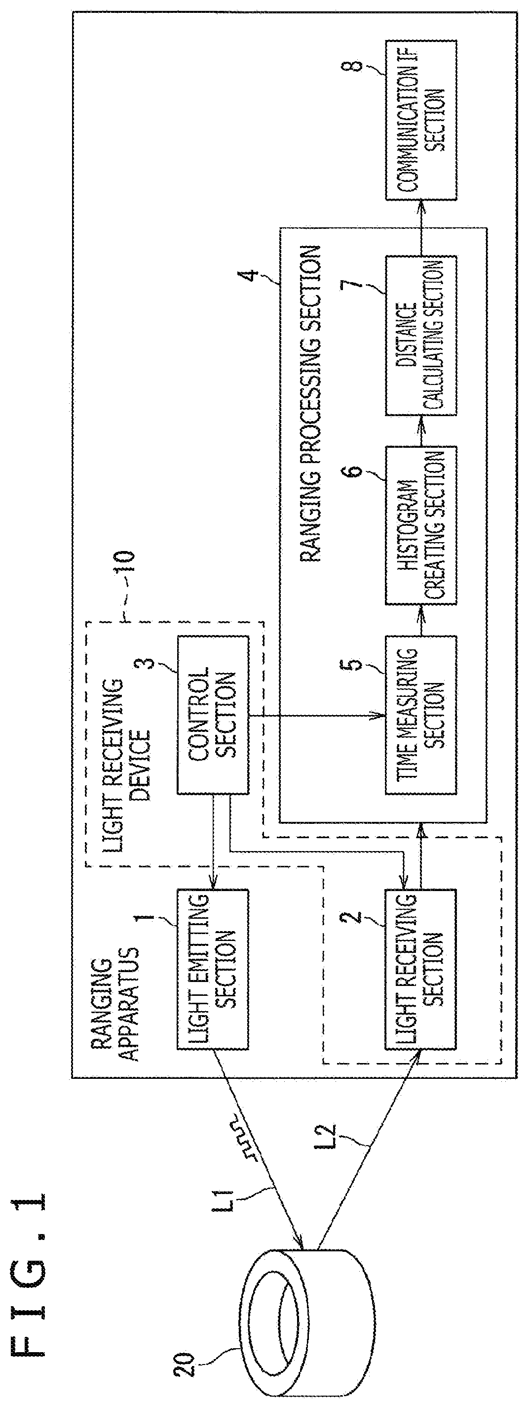
is a block diagram illustrating one example of a ranging system according to a first embodiment of the present technology.
is a schematic view of one example of the ranging system according to the first embodiment of the present technology.
is a schematic view of one example of a light receiving device according to the first embodiment of the present technology.
is a schematic view of one example of a pixel array in which active pixels are defined.
A is a schematic view of one example of an active pixel defining process.
B is a schematic view of one example of an active pixel defining process following the process in A .
C is a schematic view of one example of an active pixel defining process following the process in B .
D is a schematic view of one example of an active pixel defining process following the process in C .
A is a schematic view of another example of the pixel array in which active pixels are defined.
B is a schematic view of still another example of the pixel array in which active pixels are defined.
is a schematic view of a selection section according to a comparative example of the first embodiment of the present technology.
A is a schematic view of a selection section according to the first embodiment of the present technology.
B is a schematic view of one operation example of the selection section illustrated in A .
is a flowchart of a ranging method according to the first embodiment of the present technology.
A is a schematic view of one example of a selection section according to a first modification of the first embodiment of the present technology.
B is a schematic view of one example of a selection section according to a second modification of the first embodiment of the present technology.
is a schematic view of one example of an active pixel defining process according to a second embodiment of the present technology.
is a schematic view of a selection section according to a comparative example of the second embodiment of the present technology.
A is a schematic view of one example of a selection section according to the second embodiment of the present technology.
B is a schematic view of one operation example of the selection section illustrated in A .
is a schematic view of one example of an active pixel defining process according to a third embodiment of the present technology.
is a schematic view of a selection section according to a comparative example of the third embodiment of the present technology.
A is a schematic view of one example of a selection section according to the third embodiment of the present technology.
B is a schematic view of one operation example of the selection section illustrated in A .
DESCRIPTION OF EMBODIMENTS
Hereinafter, first to third embodiments of the present technology will be explained with reference to the drawings. Throughout the drawings to which reference will be made in the following explanation, the same or similar components are denoted by the same or similar reference signs. However, it is to be noted that, since the drawings depict schematic views, the relation between a thickness and a planar dimension, the thickness ratio of layers, and the like are different from actual ones. Therefore, specific thicknesses and specific dimensions should be determined in light of the following explanation. In addition, it goes without saying that a dimensional relation or ratio partially varies among the drawings. It is to be noted that the effects described herein are just examples and are not limitative, and further, any other effect may be provided.
First Embodiment
As illustrated in , a ranging system according to the first embodiment of the present technology is a direct ToF ranging sensor including a light emitting section 1 that emits ranging light L 1 , a light receiving section 2 that receives ranging light L 2 , a control section 3 that performs general control of the ranging system, a ranging processing section 4 that executes processes necessary to conduct ranging, and a communication interface (IF) section 8 that transmits a signal outputted from the ranging processing section 4 to an external circuit. In the ranging system according to the first embodiment of the present technology, a light receiving device 10 according to the first embodiment includes at least the light receiving section 2 and the control section 3 . The light receiving device 10 according to the first embodiment may further include the ranging processing section 4 and the communication IF section 8 .
The light emitting section 1 , the light receiving section 2 , the control section 3 , the ranging processing section 4 , and the communication IF section 8 may be monolithically and integrally formed by, for example, a System on a Chip (SoC) configuration of a Complementary Metal Oxide Semiconductor (CMOS), a Large Scale Integration (LSI), or the like. Alternatively, the light emitting section 1 and the light receiving section 2 , etc. may each be formed as a separate LSI chip. For example, the light emitting section 1 may include one chip, and the light receiving device 10 including the light receiving section 2 may include one chip.
As illustrated in , the light emitting section 1 includes a light source 11 that emits the ranging light L 1 . For example, laser light can be used as the light L 1 . For example, an edge emitting semiconductor laser or a surface emitting semiconductor laser can be used as the light source 11 . The light source 11 is driven by a trigger pulse from the control section 3 . As the trigger pulse, a rectangular pulse signal having a predetermined repetition frequency and a predetermined pulse width, for example, can be used. The light emitting section 1 has a scanning mechanism for performing raster scanning of the light L 1 . As the scanning mechanism, a mirror-scanning-type scanning mechanism including an emitter lens 12 , a projection mirror 13 , and a micromirror 14 is illustrated in .
According to a control signal from the control section 3 , the direction of a reflection surface of the micromirror 14 to reflect the light L 1 is changed. The light L 1 emitted by the light source 11 outgoes in a direction corresponding to the reflection surface of the micromirror 14 , via the emitter lens 12 , the projection mirror 13 , and the micromirror 14 . The outgoing light L 1 is reflected by an object 20 , and the reflected light (reflection light) L 2 enters the light receiving section 2 via the micromirror 14 and the projection mirror 13 . The object 20 is not limited to a particular object. An object existing around the ranging system may be used as the object 20 in a case where the ranging system is a mobile apparatus, for example. Alternatively, a pedestrian, a bicycle, a vehicle, or the like existing around a vehicle having the ranging system installed therein may be used as the object in a case where the ranging system is an on-vehicle system. Moreover, the light emitting section 1 may be a dot projector that includes no mechanical scanning mechanism, and that projects a plurality of dot patterns onto the object 20 .
The light receiving section 2 includes a receiver lens 15 and a pixel array 16 . The pixel array 16 includes multiple pixels that are arranged in a two-dimensional matrix shape. For example, as each of the pixels, a single photon avalanche diode (SPAD) that outputs an electric signal upon reacting to received light can be used. The light receiving section 2 collects the reflection light L 2 having entered the light receiving section 2 via the micromirror 14 and the projection mirror 13 , by using the receiver lens 15 , and causes a pixel that corresponds to the scanning direction of the light L 1 to receive the light L 2 . An electric signal from the pixel is outputted to the ranging processing section 4 .
The control section 3 illustrated in performs general control of operation of the ranging system. The control section 3 includes a microprocessor. The control section 3 outputs a trigger pulse to the light source 11 and a time measuring section 5 at every predetermined light-emission cycle.
On the basis of a timing of emission of the light L 1 from the light source 11 and a timing of reception of the reflection light L 2 at the light receiving section 2 , the ranging processing section 4 calculates the distance to the object 20 . The ranging processing section 4 can include a signal processor. The ranging processing section 4 includes the time measuring section 5 , a histogram creating section 6 , and a distance calculating section 7 .
For example, as the time measuring section 5 , a time measuring circuit (Time-to-Digital Converter: TDC) can be used. The time measuring section 5 converts a time interval (time of arrival) between emission of the light L 1 from the light source 11 and reception of the reflection light L 2 at a pixel to a digital value, on the basis of a trigger pulse transmitted from the control section 3 in order to drive the light source 11 and of an electric pulse signal transmitted from the light receiving section 2 . For example, a numerical value ranging from 0 to 255 can be used as the digital value. The time measuring section 5 outputs the digital value obtained by the conversion to the histogram creating section 6 .
The histogram creating section 6 creates a histogram by performing accumulation based on binary numbers (bin) obtained by the conversion at the time measuring section 5 . The histogram is held, in a memory, not illustrated, as a kind of a data structure or a table, for example. The histogram is created for each pixel. Each time receiving the digital value outputted from the time measuring section 5 , the histogram creating section 6 updates the histogram by incrementing the value of the corresponding binary number. The histogram creating section 6 outputs the created histograms to the distance calculating section 7 .
By referring to each histogram created by the histogram creating section 6 , the distance calculating section 7 detects a peak value (digital value) in the histogram and calculates the distance to the object 20 , from a time of arrival that corresponds to the detected peak value (digital value). That is, when the reflection light L 2 , which results from reflection of the emitted light L 1 by the object 20 , is received, the time of arrival represents a time interval of reciprocation to and from the object 20 . Therefore, the time of arrival is multiplied with c/2 (where c represents the speed of light), whereby the distance to the object 20 can be calculated for each pixel. Then, on the basis of the distances calculated for the respective pixels in the pixel array 16 , a distance image can be obtained. Data (ranging data) concerning the distance image is outputted to the communication IF section 8 .
The communication IF section 8 outputs, to the outside, the ranging data calculated by the ranging processing section 4 . The ranging system according to the first embodiment of the present technology is configured to be communicable with an external host IC via the communication IF section 8 , although this configuration is not illustrated. For example, as the communication IF section 8 , an interface circuit conforming to the Mobile Industry Processor Interface (MIPI), a Serial Peripheral Interface (SPI), or an Inter-Integrated Circuit (I 2 C) may be used, or an interface having one or more of these interface circuits mounted thereon may be used.
In the ranging system according to the first embodiment of the present technology, the control section 3 defines the multiple pixels constituting the pixel array 16 of the light receiving section 2 , as active pixels and non-active pixels. The control section 3 may define multiple pixel defining ranges in the pixel array 16 , and may define an active pixel in each of the multiple pixel defining ranges. In this case, in order to obtain the degree of freedom of the arrangement of active pixels, the control section 3 may define the multiple pixel defining ranges in such a way that the multiple pixel defining ranges partially overlap each other.
For example, in order to, for example, correct an al displacement during manufacturing and assembling, the control section 3 defines, as active pixels, pixels that can properly receive the reflection light L 2 , among the multiple pixels constituting the pixel array 16 of the light receiving section 2 , and further, defines, as non-active pixels, the pixels other than the active pixels. Data (correction data) for correcting an optical displacement during manufacturing and assembling may, for example, be previously measured, and be stored in a memory the illustration of which is omitted. The control section 3 may read out the correction data from the memory and define active pixels and non-active pixels on the basis of the read correction data.
Then, the control section 3 causes a signal outputted from a pixel defined as an active pixel to be outputted from the light receiving section 2 to the time measuring section 5 . For example, the control section 3 may cause only a signal outputted from a pixel defined as an active pixel to be outputted from the light receiving section 2 to the time measuring section 5 , while causing no signal outputted from a pixel defined as a non-active pixel to be outputted from the light receiving section 2 to the time measuring section 5 .
For example, it is assumed that the pixel array 16 of the light receiving section 2 has 12×12 pixels, and 5×5 active pixels among the 12×12 pixels are defined, as illustrated in . The light receiving section 2 includes a selection section 17 . An input side of the selection section 17 is connected to each of the pixels in the pixel array 16 , and an output side of the selection section 17 is connected to the time measuring section 5 . The selection section 17 can output signals outputted from 5×5=25 pixels defined as active pixels, to each of 25 time measuring circuits (TDC) constituting the time measuring section 5 , for example.
For example, by outputting a control signal to the selection section 17 , the control section 3 causes the selection section 17 to select signals outputted from the pixels defined as the active pixels only and causes the signals to be outputted to the time measuring section 5 . It is to be noted that, by outputting a control signal also to the multiple pixels constituting the pixel array 16 , the control section 3 may perform control to cause only the pixels defined as active pixels to output signals, without causing only the pixels defined as non-active pixels to output signals.
The control section 3 defines, as active pixels Pa, 5×5=25 pixels that are positioned at addresses (X, Y)=(2, 2), (2, 4), (2, 6), (2, 8), (2, 10), (4, 2), (4, 4), (4, 6), (4, 8), (4, 10), (6, 2), (6, 4), (6, 6), (6, 8), (6, 10), (8, 2), (8, 4), (8, 6), (8, 8), (8, 10), (10, 2), (10, 4), (10, 6), (10, 8), and (10, 10) which are at equal intervals in the pixel array 16 , as indicated by dot-like hatching in , for example. As a result, the pixels other than the multiple active pixels Pa are defined as non-active pixels Pb.
Here, one example of a process of defining active pixels Pa will be explained with reference to A, 5 B, 50 , and 5 D . First, as illustrated in A , the control section 3 defines, as a pixel defining range A 1 , an 8×8 pixel region on the upper left side, and further, defines, as an active pixel Pa, a pixel at an address (2, 2) in the pixel defining range A 1 . In addition, as illustrated in B , the control section 3 defines, as a pixel defining range A 2 , an 8×8 pixel region that is shifted from the pixel defining range A 1 to the right side in the horizontal direction (row direction) by one pixel, and further, defines, as an active pixel Pa, a pixel at an address (2, 4) in the pixel defining range A 2 . Here, in order to obtain the degree of freedom of the arrangement of active pixels Pa, the pixel defining ranges A 1 and A 2 are defined in such a way that the pixel defining ranges A 1 and A 2 partially overlap each other. Thereafter, the control section 3 further defines pixel defining ranges that are sequentially shifted from the pixel defining range A 2 to the right side by one pixel, and defines, as active pixels Pa, pixels at addresses (2, 6), (2, 8), and (2, 10) sequentially in the respective pixel defining ranges, although an illustration of this defining is omitted.
Further, the control section 3 defines, as a pixel defining range A 3 , an 8×8 pixel region that is shifted downward in the vertical direction (column direction) from the pixel defining range A 1 illustrated in A by one pixel, and further, defines, as an active pixel Pa, a pixel at the address (4, 2) in the pixel defining range A 3 , as illustrated in C . Likewise, the control section 3 sequentially defines a pixel defining range that is shifted to the right side from the pixel defining range A 3 by one pixel, and further, defines, as active pixels Pa, pixels at addresses (4, 4), (4, 6), (4, 8), and (4, 10) in the respective pixel defining ranges, although an illustration of this defining is omitted. Likewise, the pixel defining range is sequentially shifted in the horizontal direction and the vertical direction, and pixels at addresses (6, 2), (6, 4), (6, 6), (6, 8), (6, 10), (8, 2), (8, 4), (8, 6), (8, 8), (8, 10), (10, 2), (10, 4), (10, 6), and (10, 8) in the respective pixel defining ranges are defined as active pixels Pa. At the end of the sequential shifting, the control section 3 defines, as a pixel defining range A 4 , an 8×8 pixel region on the lower right side, and further, defines, as an active pixel Pa, a pixel at an address (10, 10) in the pixel defining range A 4 , as illustrated in D .
It is to be noted that a range to be defined as a pixel defining range and the number of the pixel defining ranges in the pixel array 16 are not limited to those illustrated in A, 5 B, 50 , and 5 D . In addition, the position of an active pixel Pa that is defined in each pixel defining range is also not limited to that illustrated in A, 5 B, 5 C, and 5 D .
For example, by using the pixel defining ranges obtained by shifting an 8×8 pixel region by one pixel as illustrated in A, 5 B, 50 , and 5 D , the control section 3 may define active pixels Pa (indicated by dot-like hatching in the drawing), which are shifted from the respective active pixels Pa illustrated in b to the right side in the horizontal direction by one pixel, and further, may define, as non-active pixels Pb, the pixels other than the active pixels Pa, as illustrated in A . Further, by using the pixel defining ranges obtained by shifting an 8×8 pixel region by one pixel, as illustrated in A, 5 B, 5 C, and 5 D , the control section 3 may define 5×5 pixels on the upper left side as active pixels Pa (indicated by dot-like hatching in the drawing), with high density, and further, may define, as non-active pixels Pb, the pixels other than the active pixels Pa, as illustrated in B .
After once defining the multiple pixels constituting the pixel array 16 as active pixels Pa and non-active pixels Pb, the control section 3 may perform switching between the active pixels Pa and the non-active pixels Pb by outputting a control signal to the selection section 17 . For example, after defining active pixels Pa and non-active pixels Pb as illustrated in , the control section 3 may perform switching to define active pixels Pa and non-active pixels Pb as illustrated in A .
Selection Section According to Comparative Example of First Embodiment
Next, prior to a detailed explanation of the selection section 17 according to the first embodiment illustrated in , a selection section 17 x according to a comparative example of the first embodiment will be explained with reference to . For convenience of illustration, illustrates a case where the selection section 17 x according to the comparative example connects 13 pixels P 0 to P 12 defined in the pixel array 16 of the light receiving section 2 , to six time measuring circuits (TDC) 50 to 55 . However, the number of the pixels P 0 to P 12 and the number of the time measuring circuits 50 to 55 are not limited to those in this case. The selection section 17 x according to the comparative example includes six selection circuits M 0 to M 5 the output sides of which are respectively connected to the six time measuring circuits (TDC) 50 to 55 .
The selection circuit M 0 selects any one of signals outputted from eight pixels P 0 to P 7 and outputs the selected signal to the time measuring circuits 50 . That is, a range consisting of the eight pixels P 0 to P 7 is defined as a pixel defining range, an active pixel from among the pixels P 0 to P 7 is defined in the pixel defining range, and a signal outputted from the active pixel is selected by the selection circuit M 0 . The selection circuit M 0 includes first-stage multiplexers M 10 , M 11 , M 12 , and M 13 , second-stage multiplexers M 20 and M 21 , and a third-stage multiplexer M 30 . The input side of the first-stage multiplexer M 10 is connected to the pixels P 0 and P 1 , and the output side of the first-stage multiplexer M 10 is connected to the input side of the second-stage multiplexer M 20 . The first-stage multiplexer M 10 performs a multiplexing process of selecting either a signal outputted from the pixel P 0 or a signal outputted from the pixel P 1 and outputting the selected signal to the second-stage multiplexer M 20 .
The input side of the first-stage multiplexer M 11 is connected to the pixels P 2 and P 3 , and the output side of the first-stage multiplexer M 11 is connected to the input side of the second-stage multiplexer M 20 . The first-stage multiplexer M 11 performs a multiplexing process of selecting either a signal outputted from the pixel P 2 or a signal outputted from the pixel P 3 and outputting the selected signal to the second-stage multiplexer M 20 .
Also, the input side of the first-stage multiplexer M 12 is connected to the pixels P 4 and P 5 , and the output side of the first-stage multiplexer M 12 is connected to the input side of the second-stage multiplexer M 21 . The first-stage multiplexer M 12 performs a multiplexing process of selecting either a signal outputted from the pixel P 4 or a signal outputted from the pixel P 5 and outputting the selected signal to the second-stage multiplexer M 21 .
Also, the input side of the first-stage multiplexer M 13 is connected to the pixels P 6 and P 7 , and the output side of the first-stage multiplexer M 13 is connected to the input side of the second-stage multiplexer M 21 . The first-stage multiplexer M 13 performs a multiplexing process of selecting either a signal outputted from the pixel P 6 or a signal outputted from the pixel P 7 and outputting the selected signal to the second-stage multiplexer M 21 .
Also, the input side of the second-stage multiplexer M 20 is connected to the output sides of the first-stage multiplexers M 10 and M 11 , and the output side of the second-stage multiplexer M 20 is connected to the input side of the third-stage multiplexer M 30 . The second-stage multiplexer M 20 performs a multiplexing process of selecting either the one signal selected and outputted by the first-stage multiplexer M 10 or the one signal selected and outputted by the first-stage multiplexer M 11 and outputting the selected signal to the third-stage multiplexer M 30 .
Also, the input side of the second-stage multiplexer M 21 is connected to the output sides of the first-stage multiplexers M 12 and M 13 , and the output side of the second-stage multiplexer M 21 is connected to the input side of the third-stage multiplexer M 30 . The second-stage multiplexer M 21 performs a multiplexing process of selecting either the one signal selected and outputted by the first-stage multiplexer M 12 or the one signal selected and outputted by the first-stage multiplexer M 13 and outputting the selected signal to the third-stage multiplexer M 30 .
Also, the input side of the third-stage multiplexer M 30 is connected to the output sides of the second-stage multiplexers M 20 and M 21 , and the output side of the third-stage multiplexer M 30 is connected to the time measuring circuit 50 . The third-stage multiplexer M 30 performs a multiplexing process of selecting either the one signal selected and outputted by the second-stage multiplexer M 20 or the one signal selected and outputted by the second-stage multiplexer M 21 and outputting the selected signal to the time measuring circuit 50 .
The selection circuit M 1 selects any one of signals outputted from eight pixels P 1 to P 8 and outputs the selected signal to the time measuring circuit 51 . That is, a region consisting of the eight pixels P 1 to P 8 is defined as a pixel defining range, an active pixel from among the pixels P 1 to P 8 is defined in the pixel defining range, and a signal outputted from the active pixel is selected by the selection circuit M 1 . The selection circuit M 1 includes first-stage multiplexers M 14 , M 15 , M 16 , and M 17 , second-stage multiplexers M 22 and M 23 , and a third-stage multiplexer M 31 . The circuit configuration of the selection circuit M 1 is similar to that of the selection circuit M 0 , and thus, a redundant explanation thereof is omitted.
The selection circuit M 2 selects any one of signals outputted from eight pixels P 2 to P 9 and outputs the selected signal to the time measuring circuit 52 . That is, a region consisting of the eight pixels P 2 to P 9 is defined as a pixel defining range, an active pixel from among the pixels P 2 to P 9 is defined in the pixel defining range, and a signal outputted from the active pixel is selected by the selection circuit M 2 . The selection circuit M 2 includes first-stage multiplexers M 18 , M 19 , M 110 , and M 111 , second-stage multiplexers M 24 and M 25 , and a third-stage multiplexer M 32 . The circuit configuration of the selection circuit M 2 is similar to that of the selection circuit M 0 , and thus, a redundant explanation thereof is omitted.
The selection circuit M 3 selects any one of signals outputted from eight pixels P 3 to P 10 and outputs the selected signal to the time measuring circuit 53 . That is, a region consisting of the eight pixels P 3 to P 10 is defined as a pixel defining range, an active pixel from among the pixels P 3 to P 10 is defined in the pixel defining range, and a signal outputted from the active pixel is selected by the selection circuit M 3 . The selection circuit M 3 includes first-stage multiplexers M 112 , M 113 , M 114 , and M 115 , second-stage multiplexers M 26 and M 27 , and a third-stage multiplexer M 33 . The circuit configuration of the selection circuit M 3 is similar to that of the selection circuit M 0 , and thus, a redundant explanation thereof is omitted.
The selection circuit M 4 selects any one of signals outputted from eight pixels P 4 to P 11 and outputs the selected signal to the time measuring circuit 54 . That is, a region consisting of the eight pixels P 4 to P 11 is defined as a pixel defining range, an active pixel from among the pixels P 4 to P 11 is defined in the pixel defining range, and a signal outputted from the active pixel is selected by the selection circuit M 4 . The selection circuit M 4 includes first-stage multiplexers M 116 , M 117 , M 118 , and M 119 , second-stage multiplexers M 28 and M 29 , and a third-stage multiplexer M 34 . The circuit configuration of the selection circuit M 4 is similar to that of the selection circuit M 0 , and thus, a redundant explanation thereof is omitted.
The selection circuit M 5 selects any one of signals outputted from eight pixels P 5 to P 12 and outputs the selected signal to the time measuring circuit 55 . That is, a region consisting of the eight pixels P 5 to P 12 is defined as a pixel defining range, an active pixel from among the pixels P 5 to P 12 is defined in the pixel defining range, and a signal outputted from the active pixel is selected by the selection circuit M 5 . The selection circuit M 5 includes first-stage multiplexers M 120 , M 121 , M 122 , and M 123 , second-stage multiplexers M 210 and M 211 , and a third-stage multiplexer M 35 . The circuit configuration of the selection circuit M 5 is similar to that of the selection circuit M 0 , and thus, a redundant explanation thereof is omitted.
With the selection section 17 x according to the comparative example illustrated in , the selection circuits M 0 to M 5 can select signals outputted from pixels defined as active pixels among the pixels P 0 to P 12 and can output the selected signals to the time measuring circuits 50 to 55 , respectively. However, in order to obtain the degree of freedom of the arrangement of active pixels, the selection section 17 x according to the comparative example includes the selection circuits M 0 to M 5 each formed of seven multiplexers in such a way that the respective pixel defining ranges of the active pixels overlap each other. Accordingly, a total of 42 multiplexers are necessary. Consequently, the circuit scale is increased, and signal paths are extended, so that timing skew between pixels is likely to be increased.
Selection Section According to First Embodiment
In contrast, A illustrates the selection section 17 according to the first embodiment of the present technology. A illustrates a case where, as with the selection section 17 x according to the comparative example illustrated in , the selection section 17 according to the first embodiment connects 13 pixels P 0 to P 12 which are defined in the pixel array 16 of the light receiving section 2 , to six time measuring circuits (TDC) 50 to 55 .
The selection section 17 according to the first embodiment of the present technology includes first-stage multiplexers M 10 , M 11 , M 12 , M 13 , M 14 , M 15 , M 16 , M 17 , M 18 , M 19 , M 110 , and M 111 , second-stage multiplexers M 20 , M 21 , M 22 , M 23 , M 24 , M 25 , M 26 , M 27 , M 28 , and M 29 , and third-stage multiplexers M 30 , M 31 , M 32 , M 33 , M 34 , and M 35 . The first-stage multiplexers M 10 to M 111 , the second-stage multiplexers M 20 to M 29 , and the third-stage multiplexers M 30 to M 35 are each connected to the control section 3 illustrated in , and are each operated according to a control signal from the control section 3 .
The input side of the first-stage multiplexer M 10 is connected to the pixels P 0 and P 1 , and the output side of the first-stage multiplexer M 10 is connected to the second-stage multiplexer M 20 . The first-stage multiplexer M 10 performs a multiplexing process of selecting either a signal outputted from the pixel P 0 or a signal outputted from the pixel P 1 and outputting the selected signal to the second-stage multiplexer M 20 .
Also, the input side of the first-stage multiplexer M 11 is connected to the pixels P 1 and P 2 , and the output side of the first-stage multiplexer M 11 is connected to the second-stage multiplexer M 21 . The first-stage multiplexer M 11 performs a multiplexing process of selecting either a signal outputted from the pixel P 1 or a signal outputted from the pixel P 2 and outputting the selected signal to the second-stage multiplexer M 21 .
Also, the input side of the first-stage multiplexer M 12 is connected to the pixels P 2 and P 3 , and the output side of the first-stage multiplexer M 12 is connected to both the second-stage multiplexers M 20 and M 22 . The first-stage multiplexer M 12 performs a multiplexing process of selecting either a signal outputted from the pixel P 2 or a signal outputted from the pixel P 3 and outputting the selected signal to the second-stage multiplexers M 20 and M 22 .
Also, the input side of the first-stage multiplexer M 13 is connected to the pixels P 3 and P 4 , and the output side of the first-stage multiplexer M 13 is connected to both the second-stage multiplexers M 21 and M 23 . The first-stage multiplexer M 13 performs a multiplexing process of selecting either a signal outputted from the pixel P 3 or a signal outputted from the pixel P 4 and outputting the selected signal to the second-stage multiplexers M 21 and M 23 .
Also, the input side of the first-stage multiplexer M 14 is connected to the pixels P 4 and P 5 , and the output side of the first-stage multiplexer M 14 is connected to both the second-stage multiplexers M 22 and M 24 . The first-stage multiplexer M 14 performs a multiplexing process of selecting either a signal outputted from the pixel P 4 or a signal outputted from the pixel P 5 and outputting the selected signal to the second-stage multiplexers M 22 and M 24 . The circuit configurations of the first-stage multiplexers M 15 to M 111 are similar to those of the first-stage multiplexers M 10 to M 14 , and thus, a redundant explanation thereof is omitted.
The input side of the second-stage multiplexer M 20 is connected to the first-stage multiplexers M 10 and M 12 , and the output side of the second-stage multiplexer M 20 is connected to the third-stage multiplexer M 30 . The second-stage multiplexer M 20 performs a multiplexing process of selecting either the one signal selected and outputted by the first-stage multiplexer M 10 or the one signal selected and outputted by the first-stage multiplexer M 12 and outputting the selected signal to the third-stage multiplexer M 30 .
Also, the input side of the second-stage multiplexer M 21 is connected to the first-stage multiplexers M 11 and M 13 , and the output side of the second-stage multiplexer M 21 is connected to the third-stage multiplexer M 31 . The second-stage multiplexer M 21 performs a multiplexing process of selecting either the one signal selected and outputted by the first-stage multiplexer M 11 or the one signal selected and outputted by the first-stage multiplexer M 13 and outputting the selected signal to the third-stage multiplexer M 31 .
Also, the input side of the second-stage multiplexer 22 is connected to the first-stage multiplexers M 12 and M 14 , and the output side of the second-stage multiplexer M 22 is connected to the third-stage multiplexer M 32 . The second-stage multiplexer M 22 performs a multiplexing process of selecting either the one signal selected and outputted by the first-stage multiplexer M 12 or the one signal selected and outputted by the first-stage multiplexer M 14 and outputting the selected signal to the third-stage multiplexer M 32 .
Also, the input side of the second-stage multiplexer M 23 is connected to the first-stage multiplexers M 13 and M 15 , and the output side of the second-stage multiplexer M 23 is connected to the third-stage multiplexer M 33 . The second-stage multiplexer M 22 performs a multiplexing process of selecting either the one signal selected and outputted by the first-stage multiplexer M 13 or the one signal selected and outputted by the first-stage multiplexer M 15 and outputting the selected signal to the third-stage multiplexer M 33 .
Also, the input side of the second-stage multiplexer M 24 is connected to the first-stage multiplexers M 14 and M 16 , and the output side of the second-stage multiplexer M 24 is connected to both the third-stage multiplexers M 30 and M 34 . The second-stage multiplexer M 24 performs a multiplexing process of selecting either the one signal selected and outputted by the first-stage multiplexer M 14 or the one signal selected and outputted by the first-stage multiplexer M 16 and outputting the selected signal to the third-stage multiplexers M 30 and 34 . The circuit configurations of the second-stage multiplexers M 25 to M 29 are similar to those of the second-stage multiplexers M 20 to M 24 , and thus, a redundant explanation thereof is omitted.
The input side of the third-stage multiplexer M 30 is connected to the second-stage multiplexers M 20 and M 24 , and the output side of the third-stage multiplexer M 30 is connected to the time measuring circuit 50 . The third-stage multiplexer M 30 performs a multiplexing process of selecting either the one signal selected and outputted by the second-stage multiplexer M 20 or the one signal selected and outputted by the second-stage multiplexer M 24 and outputting the selected signal to the time measuring circuit 50 .
Also, the input side of the third-stage multiplexer M 31 is connected to the second-stage multiplexers M 21 and M 25 , and the output side of the third-stage multiplexer M 31 is connected to the time measuring circuit 51 . The third-stage multiplexer M 31 performs a multiplexing process of selecting either the one signal selected and outputted by the second-stage multiplexer M 21 or the one signal selected and outputted by the second-stage multiplexer M 25 and outputting the selected signal to the time measuring circuit 51 .
Also, the input side of the third-stage multiplexer M 32 is connected to the second-stage multiplexers M 22 and M 26 , and the output side of the third-stage multiplexer M 32 is connected to the time measuring circuit 52 . The third-stage multiplexer M 32 performs a multiplexing process of selecting either the one signal selected and outputted by the second-stage multiplexer M 22 or the one signal selected and outputted by the second-stage multiplexer M 26 and outputting the selected signal to the time measuring circuit 52 . The circuit configurations of the third-stage multiplexers M 33 to M 35 are similar to those of the third-stage multiplexers M 30 to M 32 , and thus, a redundant explanation thereof is omitted.
In the selection section 17 according to the first embodiment of the present technology, the multiplexers, for which the pixel defining ranges overlap each other in the selection section 17 x according to the comparative example illustrated in , are adaptable to sharing usage. That is, by modifying the two first-stage multiplexers M 11 and M 18 in the selection section 17 x according to the comparative example illustrated in so as to be adaptable to sharing usage, the single first-stage multiplexer M 12 in the selection section 17 according to the first embodiment illustrated in A is obtained. In addition, by modifying the two first-stage multiplexers M 15 and M 112 of the selection section 17 x according to the comparative example illustrated in so as to be adaptable to sharing usage, the single first-stage multiplexer M 13 of the selection section 17 according to the first embodiment illustrated in A is obtained.
Also, by modifying the three first-stage multiplexers M 12 , M 19 , and M 116 of the selection section 17 x according to the comparative example illustrated in so as to be adaptable to sharing usage, the single first-stage multiplexer M 14 of the selection section 17 according to the first embodiment illustrated in A is obtained. Also, by modifying the three first-stage multiplexers M 16 , M 113 , and M 120 of the selection section 17 x according to the comparative example illustrated in so as to be adaptable to sharing usage, the single first-stage multiplexer M 15 of the selection section 17 according to the first embodiment illustrated in A is obtained. Also, by modifying the three first-stage multiplexers M 13 , M 110 , and M 117 of the selection section 17 x according to the comparative example illustrated in so as to be adaptable to sharing usage, the single first-stage multiplexer M 16 of the selection section 17 according to the first embodiment illustrated in A is obtained. Also, by modifying the three first-stage multiplexers M 17 , M 114 , M 121 of the selection section 17 x according to the comparative example illustrated in so as to be adaptable to sharing usage, the single first-stage multiplexer M 17 of the selection section 17 according to the first embodiment illustrated in A is obtained.
Also, by modifying the two first-stage multiplexers M 111 and M 118 of the selection section 17 x according to the comparative example illustrated in so as to be adaptable to sharing usage, the single first-stage multiplexer M 18 of the selection section 17 according to the first embodiment illustrated in A is obtained. Also, by modifying the two first-stage multiplexers M 115 and M 122 of the selection section 17 x according to the comparative example illustrated in so as to be adaptable to sharing usage, the single first-stage multiplexer M 19 of the selection section 17 according to the first embodiment illustrated in A is obtained.
Also, by modifying the two second-stage multiplexers M 21 and M 28 of the selection section 17 x according to the comparative example illustrated in so as to be adaptable to sharing usage, the single second-stage multiplexer M 24 of the selection section 17 according to the first embodiment illustrated in A is obtained. Also, by modifying the two second-stage multiplexers M 23 and M 210 of the selection section 17 x according to the comparative example illustrated in so as to be adaptable to sharing usage, the single second-stage multiplexer M 25 of the selection section 17 according to the first embodiment illustrated in A is obtained.
Accordingly, the selection section 17 according to the first embodiment illustrated in A can be formed of a total of 28 multiplexers. Therefore, the circuit scale can be reduced, and timing skew can be improved, compared to the selection section 17 x according to the comparative example illustrated in .
In addition, since the multiplexers are set to be adaptable to sharing usage, the selection section 17 according to the first embodiment illustrated in A is subjected to a constraint that two inputs cannot be simultaneously used at a multiplexer modified for sharing usage. However, if the time measuring circuits 50 to 55 are properly connected, any arrangement of active pixels can be realized. Accordingly, the same degree of freedom can be obtained in terms of the functions.
For example, it is assumed that the selection section 17 according to the first embodiment is used to define the pixels P 2 and P 3 as active pixels, as illustrated in B . In B , selected paths from the pixels P 2 and P 3 to the time measuring circuits 51 and 52 are highlighted with thick lines. A signal outputted by the pixel P 2 is selected by the first-stage multiplexer M 11 , the second-stage multiplexer M 21 , and the third-stage multiplexer M 31 , and is outputted to the time measuring circuit 51 . A signal outputted by the pixel P 3 is selected by the first-stage multiplexer M 12 , the second-stage multiplexer M 22 , and the third-stage multiplexer M 32 , and is outputted to the time measuring circuit 52 . In such a manner, in a case where the pixels P 2 and P 3 are defined as active pixels, the pixels P 2 and P 3 cannot be connected to the time measuring circuits 50 and 52 , respectively, but can be connected to the time measuring circuits 51 and 52 , respectively.
Next, one example of a ranging method according to the first embodiment including a light receiving method which is performed by the light receiving device 10 according to the first embodiment will be explained with reference to a flowchart in .
In step S 1 , the control section 3 illustrated in defines multiple pixels constituting the pixel array 16 in the light receiving section 2 , as active pixels and non-active pixels. In order to, for example, correct an optical displacement during manufacturing and assembling, the control section 3 defines, among the multiple pixels constituting the pixel array 16 in the light receiving section 2 , pixels that can properly receive the reflection light L 2 as active pixels, and defines the pixels other than the active pixels as non-active pixels.
In step S 2 , the light emitting section 1 emits the ranging light L 1 . In step S 3 , the light receiving section 2 receives the ranging light L 2 . In step S 4 , the control section 3 causes signals outputted from pixels defined as the active pixels in step S 1 to be outputted from the light receiving section 2 to the time measuring section 5 .
In steps S 5 to S 7 , on the basis of a timing of emission of the light L 1 from the light source 11 and a timing of reception of the reflection light L 2 at the light receiving section 2 , the ranging processing section 4 calculates the distance to the object 20 . That is, in step S 5 , the time measuring section 5 converts a time interval (time of arrival) between the emission of the light L 1 from the light source 11 in step S 2 and the reception of the reflection light L 2 at a pixel in step S 3 to a digital value, on the basis of a trigger pulse transmitted from the control section 3 in order to drive the light source 11 and of an electric pulse signal transmitted from the light receiving section 2 . In step S 6 , the histogram creating section 6 creates a histogram by performing accumulation based on the digital values obtained by the conversion at the time measuring section 5 . In step S 7 , by referring to the histograms created by the histogram creating section 6 , the distance calculating section 7 detects the peak values (digital values) in the respective histograms and calculates the distance to the object 20 from the times of arrival corresponding to the detected peak values (digital values).
Effects of First Embodiment
In the ranging system and the light receiving device 10 according to the first embodiment, the control section 3 defines the multiple pixels in the pixel array 16 of the light receiving section 2 as active pixels and non-active pixels, as explained so far. Further, signals outputted from the pixels defined as the active pixels are outputted from the light receiving section 2 . Accordingly, an optical displacement such as an aberration or a magnification in a light spot during manufacturing and assembling, etc. can be corrected.
Moreover, since the selection section 17 according to the first embodiment illustrated in A is provided, switching between an active pixel and a non-active pixel can be properly performed. In addition, the circuit scale can be reduced, and timing skew can be improved, compared to the selection section 17 x according to the comparative example illustrated in . It is to be noted that, although the case where the 12 pixels P 0 to P 12 and the six time measuring circuits 50 to 55 are provided is illustrated in A , the number of the pixels P 0 to P 12 and the number of the time measuring circuits 50 to 55 are not limited those in this case. The circuit scale of the selection section 17 according to the first embodiment illustrated in A may be increased or reduced according to an increase or a decrease in the number of the pixels P 0 to P 12 or the number of the time measuring circuits 50 to 55 .
First Modification of First Embodiment
As illustrated in A , a selection section 17 a according to a first modification of the first embodiment of the present technology includes the first-stage multiplexers M 10 , M 11 , M 12 , M 13 , M 14 , M 15 , M 16 , M 17 , M 18 , M 19 , M 110 , and M 111 , and the second-stage multiplexers M 20 , M 21 , M 22 , M 23 , M 24 , M 25 , M 26 , M 27 , M 28 , and M 29 , as in the selection section 17 according to the first embodiment illustrated in A . However, unlike the selection section 17 according to the first embodiment illustrated in A , the selection section 17 a according to the first modification includes no third-stage multiplexer.
As illustrated in A , the second-stage multiplexers M 20 to M 29 in the selection section 17 a are respectively connected to 10 time measuring circuits (TDC) 50 to 59 . The selection section 17 a according to the first modification can be formed of a total of 22 multiplexers. According to the first modification of the first embodiment of the present technology, the selection section 17 a can have a two-stage configuration, and further, the number of the time measuring circuits 50 to 59 can be selected as appropriate. It is to be noted that the selection section may be formed of multiplexers of four or more stages.
Second Modification of First Embodiment
As illustrated in B , a selection section 17 b according to a second modification of the first embodiment of the present technology has a configuration in which the first-stage multiplexers M 12 , M 13 , M 14 , M 15 , M 16 , M 17 , M 18 , and M 19 are adaptable to sharing usage, as in the selection section 17 according to the first embodiment illustrated in A . However, unlike the selection section 17 according to the first embodiment illustrated in A , the selection section 17 b according to the second modification has a configuration in which the second-stage multiplexers M 24 and M 25 are not adaptable to sharing usage.
As illustrated in B , the input side of the third-stage multiplexer M 30 in the selection section 17 b according to the second modification is connected to the second-stage multiplexers M 20 and 21 . The input side of the third-stage multiplexer M 31 is connected to the second-stage multiplexers M 22 and 23 . The input side of the third-stage multiplexer M 32 is connected to the second-stage multiplexers M 24 and 25 . The input side of the third-stage multiplexer M 33 is connected to the second-stage multiplexers M 26 and 27 . The input side of the third-stage multiplexer M 34 is connected to the second-stage multiplexers M 28 and 29 . The output sides of the third-stage multiplexers M 30 to M 34 are respectively connected to five time measuring circuits (TDC) 50 to 54 . The selection section 17 b according to the second modification can be formed of a total of 27 multiplexers. According to the first modification of the first embodiment of the present technology, the multiplexers of at least the first stage in the selection section 17 b are adaptable to sharing usage. Accordingly, the circuit scale of the selection section 17 b can be reduced.
Second Embodiment
A ranging system according to the second embodiment of the present technology has a configuration similar to that of the ranging system according to the first embodiment illustrated in . In the second embodiment, among 12×12 pixels constituting the pixel array 16 of the light receiving section 2 illustrated in , pixels P 1 to P 5 are defined in five pixel defining ranges A 1 to A 5 , as illustrated in . The pixel defining ranges A 1 to A 5 are each defined by 8×8 pixels, and are shifted from each other in the horizontal direction by one pixel.
Selection Section According to Comparative Example of Second Embodiment
Prior to an explanation of a selection section according to the second embodiment, a selection section 17 y according to a comparative example of the second embodiment will be explained with reference to . The selection section 17 y according to the comparative example includes vertical-direction selection circuits M 00 , M 01 , M 02 , M 03 , M 04 , M 05 , M 06 , M 07 , M 08 , M 09 , M 10 , and M 011 , and horizontal-direction selection circuits M 0 , M 1 , M 2 , M 3 , and M 4 . The input side of the selection circuit M 00 is connected to eight pixels at addresses (X, Y)=(1, 1), (1, 2), (1, 3), (1, 4), . . . , and (1, 8), and the output side of the selection circuit M 00 is connected to the selection circuit M 0 . The selection circuit M 00 selects any one of signals outputted from the eight pixels at addresses (X, Y)=(1, 1), (1, 2), (1, 3), (1, 4), . . . , and (1, 8), and outputs the selected signal to the selection circuit M 0 .
The input side of the selection circuit M 01 is connected to eight pixels at addresses (2, 1), (2, 2), (2, 3), (2, 4), . . . , and (2, 8), and the output side of the selection circuit M 01 is connected to the selection circuits M 0 and M 1 . The selection circuit M 01 selects any one of signals outputted from the eight pixels at addresses (2, 1), (2, 2), (2, 3), (2, 4), . . . , and (2, 8), and outputs the selected signal to the selection circuits M 0 and M 1 . The circuit configurations of the selection circuits M 02 to M 011 are similar to those of the selection circuits M 00 and M 01 , and thus, a redundant explanation thereof is omitted.
The output sides of the horizontal-direction selection circuits M 0 to M 4 are connected to five time measuring circuits (TDC) 50 to 54 . The selection circuits M 0 to M 4 select signals outputted from the active pixels P 1 to P 5 defined in the pixel defining ranges A 1 to A 5 illustrated in and output the selected signals to the time measuring circuits 50 to 54 , respectively.
The selection circuit M 0 selects either the one signal selected and outputted by the selection circuit M 00 or the one signal selected and outputted by the selection circuit M 01 and outputs the selected signal to the time measuring circuit 50 . The selection circuit M 0 includes the first-stage multiplexers M 10 , M 11 , M 12 , and M 13 , the second-stage multiplexers M 20 and M 21 , and the third-stage multiplexer M 30 .
The input side of the first-stage multiplexer M 10 is connected to the selection circuits M 00 and M 01 , and the output side of the first-stage multiplexer M 10 is connected to the input side of the second-stage multiplexer M 20 . The first-stage multiplexer M 10 performs a multiplexing process of selecting either the one signal selected and outputted by the selection circuit M 00 or the one signal selected and outputted by the selection circuit M 01 and outputting the selected signal to the second-stage multiplexer M 20 .
Also, the input side of the first-stage multiplexer M 11 is connected to the selection circuits M 02 and M 03 , and the output side of the first-stage multiplexer M 11 is connected to the input side of the second-stage multiplexer M 20 . The first-stage multiplexer M 11 performs a multiplexing process of selecting either the one signal selected and outputted by the selection circuit M 02 or the one signal selected and outputted by the selection circuit M 03 and outputting the selected signal to the second-stage multiplexer M 20 .
Also, the input side of the first-stage multiplexer M 12 is connected to the selection circuits M 04 and M 05 , and the output side of the first-stage multiplexer M 12 is connected to the input side of the second-stage multiplexer M 21 . The first-stage multiplexer M 12 performs a multiplexing process of selecting either the one signal selected and outputted by the selection circuit M 04 or the one signal selected and outputted by the selection circuit M 05 and outputting the selected signal to the second-stage multiplexer M 21 .
Also, the input side of the first-stage multiplexer M 13 is connected to the selection circuits M 06 and M 07 , and the output side of the first-stage multiplexer M 13 is connected to the input side of the second-stage multiplexer M 21 . The first-stage multiplexer M 13 performs a multiplexing process of selecting either the one signal selected and outputted by the selection circuit M 06 or the one signal selected and outputted by the selection circuit M 07 and outputting the selected signal to the second-stage multiplexer M 21 .
Also, the input side of the second-stage multiplexer M 20 is connected to the output sides of the first-stage multiplexers M 10 and M 11 , and the output side of the second-stage multiplexer M 20 is connected to the input side of the third-stage multiplexer M 30 . The second-stage multiplexer M 20 performs a multiplexing process of selecting either the one signal selected and outputted by the first-stage multiplexer M 10 or the one signal selected and outputted by the first-stage multiplexer M 11 and outputting the selected signal to the third-stage multiplexer M 30 .
Also, the input side of the second-stage multiplexer M 21 is connected to the output sides of the first-stage multiplexers M 12 and M 13 , and the output side of the second-stage multiplexer M 21 is connected to the input side of the third-stage multiplexer M 30 . The second-stage multiplexer M 21 performs a multiplexing process of selecting either the one signal selected and outputted by the first-stage multiplexer M 12 or the one signal selected and outputted by the first-stage multiplexer M 13 and outputting the selected signal to the third-stage multiplexer M 30 .
Also, the input side of the third-stage multiplexer M 30 is connected to the output sides of the second-stage multiplexers M 20 and M 21 , and the output side of the third-stage multiplexer M 30 is connected to the time measuring circuit 50 . The third-stage multiplexer M 30 performs a multiplexing process of selecting either the one signal selected and outputted by the second-stage multiplexer M 20 or the one signal selected and outputted by the second-stage multiplexer M 21 , and outputs the selected signal to the time measuring circuit 50 .
The selection circuit M 1 selects any one of signals respectively selected and outputted by the selection circuits M 01 to M 08 and outputs the selected signal to the time measuring circuit 51 . The selection circuit M 1 includes the first-stage multiplexers M 14 , M 15 , M 16 , and M 17 , the second-stage multiplexers M 22 and M 23 , and the third-stage multiplexer M 31 . The circuit configuration of the selection circuit M 1 is similar to that of the selection circuit M 0 , and thus, a redundant explanation thereof is omitted.
The selection circuit M 2 selects any one of signals respectively selected and outputted by the selection circuits M 02 to M 09 and outputs the selected signal to the time measuring circuit 52 . The selection circuit M 2 includes the first-stage multiplexers M 18 , M 19 , M 110 , and M 111 , the second-stage multiplexers M 24 and M 25 , and the third-stage multiplexer M 32 . The circuit configuration of the selection circuit M 2 is similar to that of the selection circuit M 0 , and thus, a redundant explanation thereof is omitted.
The selection circuit M 3 selects any one of signals respectively selected and outputted by the selection circuits M 03 to M 010 and outputs the selected signal to the time measuring circuit 53 . The selection circuit M 3 includes the first-stage multiplexers M 112 , M 113 , M 114 , and M 115 , the second-stage multiplexers M 26 and M 27 , and the third-stage multiplexer M 33 . The circuit configuration of the selection circuit M 3 is similar to that of the selection circuit M 0 , and thus, a redundant explanation thereof is omitted.
The selection circuit M 4 selects any one of signals respectively selected and outputted by the selection circuits M 04 to M 011 and outputs the selected signal to the time measuring circuit 54 . The selection circuit M 4 includes the first-stage multiplexers M 116 , M 117 , M 118 , and M 119 , the second-stage multiplexers M 28 and M 29 , and the third-stage multiplexer M 34 . The circuit configuration of the selection circuit M 4 is similar to that of the selection circuit M 0 , and thus, a redundant explanation thereof is omitted.
With the selection section 17 y according to the comparative example of the second embodiment illustrated in , signals outputted from the pixels defined as active pixels in the pixel defining ranges A 1 to A 5 in the pixel array 16 illustrated in can be selected and be outputted to the time measuring circuits 50 to 54 . However, in the selection section 17 y according to the comparative example of the second embodiment, the selection circuits M 0 to M 4 of are each formed of seven multiplexers. Accordingly, a total of 35 multiplexers are necessary. Consequently, the circuit scale is increased, and signal paths are extended, so that timing skew between pixels is likely to be increased.
Selection Section According to Second Embodiment
In contrast, a selection section 17 c according to the second embodiment of the present technology will be explained with reference to A . As with the selection section 17 y according to the comparative example illustrated in , the selection section 17 c according to the second embodiment selects signals respectively outputted from the active pixels P 1 to P 5 defined in the pixel defining ranges A 1 to A 5 illustrated in and outputs the signals to the time measuring circuits 50 to 54 . The configurations of the vertical-direction selection circuits M 00 to M 011 in the selection section 17 c according to the second embodiment are identical to those of the selection circuits M 00 to M 011 in the selection section 17 y according to the comparative example illustrated in . However, the configuration of a horizontal-direction selection circuit M 012 in the selection section 17 c according to the second embodiment is different from those of the selection circuits M 0 to M 4 in the selection section 17 y according to the comparative example illustrated in .
The horizontal-direction selection circuit M 012 includes the first-stage multiplexers M 10 , M 11 , M 12 , M 13 , M 14 , M 15 , M 16 , M 17 , M 18 , M 19 , and M 110 , the second-stage multiplexers M 20 , M 21 , M 22 , M 23 , M 24 , M 25 , M 26 , M 27 , and M 28 , and the third-stage multiplexers M 30 , M 31 , M 32 , M 33 , and M 34 . The first-stage multiplexers M 10 to M 110 , the second-stage multiplexers M 20 to M 28 , and the third-stage multiplexers M 30 to M 34 are each connected to the control section 3 illustrated in and are each operated according to a control signal from the control section 3 .
The input side of the first-stage multiplexer M 10 is connected to the selection circuits M 00 and M 01 , and the output side of the first-stage multiplexer M 10 is connected to the second-stage multiplexer M 20 . The first-stage multiplexer M 10 performs a multiplexing process of selecting either the one signal selected and outputted by the selection circuit M 00 or the one signal selected and outputted by the selection circuit M 01 and outputting the selected signal to the second-stage multiplexer M 20 .
Also, the input side of the first-stage multiplexer M 11 is connected to the selection circuits M 01 and M 02 , and the output side of the first-stage multiplexer M 11 is connected to the second-stage multiplexer M 21 . The first-stage multiplexer M 11 performs a multiplexing process of selecting either the one signal selected and outputted by the selection circuit M 01 or the one signal selected and outputted by the selection circuit M 02 and outputting the selected signal to the second-stage multiplexer M 21 .
Also, the input side of the first-stage multiplexer M 12 is connected to the selection circuits M 02 and M 03 , and the output side of the first-stage multiplexer M 12 is connected to both the second-stage multiplexers M 20 and M 22 . The first-stage multiplexer M 12 performs a multiplexing process of selecting either the one signal selected and outputted by the selection circuit M 02 or the one signal selected and outputted by the selection circuit M 03 and outputting the selected signal to the second-stage multiplexers M 20 and M 22 .
Also, the input side of the first-stage multiplexer M 13 is connected to the selection circuits M 03 and M 04 , and the output side of the first-stage multiplexer M 13 is connected to both the second-stage multiplexers M 21 and M 22 . The first-stage multiplexer M 13 performs a multiplexing process of selecting either the one signal selected and outputted by the selection circuit M 03 or the one signal selected and outputted by the selection circuit M 04 and outputting the selected signal to the second-stage multiplexers M 21 and M 23 .
Also, the input side of the first-stage multiplexer M 14 is connected to the selection circuits M 04 and M 05 , and the output side of the first-stage multiplexer M 14 is connected to both the second-stage multiplexers M 22 and M 24 . The first-stage multiplexer M 14 performs a multiplexing process of selecting either the one signal selected and outputted by the selection circuit M 04 or the one signal selected and outputted by the selection circuit M 05 and outputting the selected signal to the second-stage multiplexers M 22 and M 24 . The circuit configurations of the first-stage multiplexers M 15 to M 110 are similar to those of the first-stage multiplexers M 10 to M 14 , and thus, a redundant explanation thereof is omitted.
The input side of the second-stage multiplexer M 20 is connected to the first-stage multiplexers M 10 and M 12 , and the output side of the second-stage multiplexer M 20 is connected to the third-stage multiplexer M 30 . The second-stage multiplexer M 20 performs a multiplexing process of selecting either the one signal selected and outputted by the first-stage multiplexer M 10 or the one signal selected and outputted by the first-stage multiplexer M 12 and outputting the selected signal to the third-stage multiplexer M 30 .
Also, the input side of the second-stage multiplexer M 21 is connected to the first-stage multiplexers M 11 and M 13 , and the output side of the second-stage multiplexer M 21 is connected to the third-stage multiplexer M 31 . The second-stage multiplexer M 21 performs a multiplexing process of selecting either the one signal selected and outputted by the first-stage multiplexer M 11 or the one signal selected and outputted by the first-stage multiplexer M 13 and outputting the selected signal to the third-stage multiplexer M 31 .
Also, the input side of the second-stage multiplexer M 22 is connected to the first-stage multiplexers M 12 and M 14 , and the output side of the second-stage multiplexer M 22 is connected to the third-stage multiplexer M 32 . The second-stage multiplexer M 22 performs a multiplexing process of selecting either the one signal selected and outputted by the first-stage multiplexer M 12 or the one signal selected and outputted by the first-stage multiplexer M 14 and outputting the selected signal to the third-stage multiplexer M 32 .
Also, the input side of the second-stage multiplexer M 23 is connected to the first-stage multiplexers M 13 and M 15 , and the output side of the second-stage multiplexer M 23 is connected to the third-stage multiplexer M 33 . The second-stage multiplexer M 23 performs a multiplexing process of selecting either the one signal selected and outputted by the first-stage multiplexer M 13 or the one signal selected and outputted by the first-stage multiplexer M 15 and outputting the selected signal to the third-stage multiplexer M 33 .
Also, the input side of the second-stage multiplexer M 24 is connected to the first-stage multiplexers M 14 and M 16 , and the output side of the second-stage multiplexer M 22 is connected to both the third-stage multiplexers M 30 and M 34 . The second-stage multiplexer M 24 performs a multiplexing process of selecting either the one signal selected and outputted by the first-stage multiplexer M 14 or the one signal selected and outputted by the first-stage multiplexer M 16 and outputting the selected signal to the third-stage multiplexers M 30 and M 34 . The circuit configurations of the second-stage multiplexers M 25 to M 28 are similar to those of the second-stage multiplexers M 20 to M 24 , and thus, a redundant explanation thereof is omitted.
The input side of the third-stage multiplexer M 30 is connected to the second-stage multiplexers M 20 and M 24 , and the output side of the third-stage multiplexer M 30 is connected to the time measuring circuit 50 . The third-stage multiplexer M 30 performs a multiplexing process of selecting either the one signal selected and outputted by the second-stage multiplexer M 20 or the one signal selected and outputted by the second-stage multiplexer M 24 and outputting the selected signal to the time measuring circuit 50 .
Also, the input side of the third-stage multiplexer M 31 is connected to the second-stage multiplexers M 21 and M 25 , and the output side of the third-stage multiplexer M 31 is connected to the time measuring circuit 51 . The third-stage multiplexer M 31 performs a multiplexing process of selecting either the one signal selected and outputted by the second-stage multiplexer M 21 or the one signal selected and outputted by the second-stage multiplexer M 25 and outputting the selected signal to the time measuring circuit 51 .
Also, the input side of the third-stage multiplexer M 32 is connected to the second-stage multiplexers M 22 and M 26 , and the output side of the third-stage multiplexer M 32 is connected to the time measuring circuit 52 . The third-stage multiplexer M 32 performs a multiplexing process of selecting either the one signal selected and outputted by the second-stage multiplexer M 22 or the one signal selected and outputted by the second-stage multiplexer M 26 and outputting the selected signal to the time measuring circuit 52 . The circuit configurations of the third-stage multiplexers M 33 and M 34 are similar to those of the third-stage multiplexers M 30 to M 32 , and thus, a redundant explanation thereof is omitted.
In the selection section 17 c according to the second embodiment of the present technology, the multiplexers, for which pixel defining ranges overlap each other in the selection section 17 y according to the comparative example illustrated in , are adaptable to sharing usage. That is, by modifying the two first-stage multiplexers M 11 and M 18 in the selection section 17 y according to the comparative example illustrated in so as to be adaptable to sharing usage, the single first-stage multiplexer M 12 in the selection section 17 c according to the second embodiment illustrated in A is obtained. Also, by modifying the two first-stage multiplexers M 15 and M 112 in the selection section 17 y according to the comparative example illustrated in so as to be adaptable to sharing usage, the single first-stage multiplexer M 13 in the selection section 17 c according to the second embodiment illustrated in A is obtained.
Also, by modifying the three first-stage multiplexers M 12 , M 19 , and M 116 in the selection section 17 y according to the comparative example illustrated in so as to be adaptable to sharing usage, the single first-stage multiplexer M 14 in the selection section 17 c according to the second embodiment illustrated in A is obtained. Also, by modifying the two first-stage multiplexers M 16 and M 113 in the selection section 17 y according to the comparative example illustrated in so as to be adaptable to sharing usage, the single first-stage multiplexer M 15 in the selection section 17 c according to the second embodiment illustrated in A is obtained.
Also, by modifying the three first-stage multiplexers M 13 , M 110 , and M 117 in the selection section 17 y according to the comparative example illustrated in so as to be adaptable to sharing usage, the single first-stage multiplexer M 16 in the selection section 17 c according to the second embodiment illustrated in A is obtained. Also, by modifying the two first-stage multiplexers M 17 and M 114 in the selection section 17 y according to the comparative example illustrated in so as to be adaptable to sharing usage, the single first-stage multiplexer M 17 in the selection section 17 c according to the second embodiment illustrated in A is obtained. Also, by modifying the two first-stage multiplexers M 111 and M 118 in the selection section 17 y according to the comparative example illustrated in so as to be adaptable to sharing usage, the single first-stage multiplexer M 18 in the selection section 17 c according to the second embodiment illustrated in A is obtained.
Also, by modifying the two second-stage multiplexers M 21 and M 28 in the selection section 17 y according to the comparative example illustrated in so as to be adaptable to sharing usage, the single second-stage multiplexer M 24 in the selection section 17 c according to the second embodiment illustrated in A is obtained. Accordingly, the selection section 17 c according to the second embodiment of the present technology can be formed of a total of 28 multiplexers. Therefore, the circuit scale can be reduced, and timing skew can be improved, compared to the selection section 17 y according to the comparative example illustrated in .
In addition, since the multiplexers are set to be adaptable to sharing usage, the selection section 17 c according to the second embodiment illustrated in A is subjected to a constraint that two inputs cannot be simultaneously used at a multiplexer modified for sharing usage. However, if the time measuring circuits 50 to 54 are properly connected, any arrangement of active pixels can be realized. Accordingly, the same degree of freedom can be obtained in terms of the functions.
For example, it is assumed that active pixels P 1 to P 5 are defined at addresses (X, Y)=(2, 2), (4, 2), (6, 2), (8, 2), and (10, 2), as illustrated in . In this case, paths from the five pixels at addresses (2, 2), (4, 2), (6, 2), (8, 2), and (10, 2) to the time measuring circuits 50 to 54 are selected, as highlighted with thick lines in B .
Specifically, a signal outputted from the pixel at the address (2, 2) is selected by the vertical-direction selection circuit M 01 , is further selected by the first-stage multiplexer M 10 , the second-stage multiplexer M 20 , and the third-stage multiplexer M 30 in the horizontal-direction selection circuit M 012 , and is outputted to the time measuring circuit 50 . A signal outputted from the pixel at the address (4, 2) is selected by the vertical-direction selection circuit M 03 , is further selected by the first-stage multiplexer M 13 , the second-stage multiplexer M 21 , and the third-stage multiplexer M 31 in the horizontal-direction selection circuit M 012 , and is outputted to the time measuring circuit 51 .
A signal outputted from the pixel at the address (6, 2) is selected by the vertical-direction selection circuit M 05 , is further selected by the first-stage multiplexer M 14 , the second-stage multiplexer M 22 , and the third-stage multiplexer M 32 in the horizontal-direction selection circuit M 012 , and is outputted to the time measuring circuit 52 . A signal outputted from the pixel at the address (8, 2) is selected by the vertical-direction selection circuit M 07 , is further selected by the first-stage multiplexer M 17 , the second-stage multiplexer M 27 , and the third-stage multiplexer M 33 in the horizontal-direction selection circuit M 012 , and is outputted to the time measuring circuit 53 . A signal outputted from the pixel at the address (10, 2) is selected by the vertical-direction selection circuit M 09 , is further selected by the first-stage multiplexer M 18 , the second-stage multiplexer M 28 , and the third-stage multiplexer M 34 in the horizontal-direction selection circuit M 012 , and is outputted to the time measuring circuit 54 .
Effects of Second Embodiment
In the ranging system according to the second embodiment, the control section 3 defines the multiple pixels in the pixel array 16 of the light receiving section 2 as active pixels and non-active pixels, as explained so far. Further, signals outputted from the pixels defined as the active pixels are outputted from the light receiving section 2 to the ranging processing section 4 . Accordingly, when active pixels are properly defined, an optical displacement such as an aberration or a magnification in a light spot during manufacturing and assembling, etc. can be corrected.
Moreover, since the selection section 17 c according to the second embodiment illustrated in A is provided in the ranging system according to the second embodiment, switching between an active pixel and a non-active pixel can be properly performed. In addition, compared to the selection section 17 y according to the comparative example illustrated in , the circuit scale can be reduced, and timing skew can be improved, because the multiplexers are adaptable to sharing usage.
It is to be noted that the selection section 17 c according to the second embodiment illustrated in A is an example, and the selection section is not limited thereto. For example, although the selection circuit M 012 in the selection section 17 c according to the second embodiment illustrated in A has a three-stage configuration, the selection circuit may have a two-stage configuration as in the selection section 17 a illustrated in A , and only the multiplexers at the first stage may be adaptable to sharing usage as in the selection section 17 b illustrated in B .
Third Embodiment
A ranging system according to the third embodiment of the present technology has a configuration similar to that of the ranging system according to the first embodiment illustrated in . The third embodiment is exemplified by a case where pixels P 1 to P 6 of six pixel defining ranges A 1 to A 6 are defined in the pixel array 16 which is formed of 12×12 pixels in the light receiving section 2 , as illustrated in . The pixel defining ranges A 1 to A 6 are defined so as to partially overlap each other. The pixel defining ranges A 1 to A 3 are each defined into an 8×8 pixel region and are shifted from each other in the horizontal direction by two pixels. The pixel defining ranges A 4 to A 6 are each defined into an 8×8 pixel region, are respectively shifted in the vertical direction from the pixel defining ranges A 1 to A 3 by four pixels, and are shifted from each other in the horizontal direction by two pixels.
Selection Section According to Comparative Example of Third Embodiment
Here, prior to an explanation of a selection section according to the third embodiment, a selection section 17 z according to a comparative example of the third embodiment will be explained with reference to . The selection section 17 z according to the comparative example includes vertical-direction and horizontal-direction selection circuits M 00 , M 01 , M 02 , M 03 , M 04 , M 05 , M 06 , M 07 , M 08 , M 09 , M 10 , M 011 , M 012 , M 013 , M 014 , M 015 , M 016 , and M 017 , and vertical-direction and horizontal-direction selection circuits M 0 , M 1 , M 2 , M 3 , M 4 , and M 5 .
The input side of the selection circuit M 00 is connected to eight pixels at addresses (X, Y)=(1, 1), (1, 2), (1, 3), (1, 4), (2, 1), (2, 2), (2, 3), and (2, 4), and the output side of the selection circuit M 00 is connected to the selection circuit M 0 . The selection circuit M 00 selects any one of signals outputted from the eight pixels at addresses (1, 1), (1, 2), (1, 3), (1, 4), (2, 1), (2, 2), (2, 3), and (2, 4), and outputs the selected signal to the selection circuit M 0 .
The input side of the selection circuit M 01 is connected to eight pixels at addresses (1, 5), (1, 6), (1, 7), (1, 8), (2, 5), (2, 6), (2, 7), and (2, 8), and the output side of the selection circuit M 01 is connected to the selection circuits M 0 and M 3 . The selection circuit M 01 selects any one of signals outputted from the eight pixels at addresses (1, 5), (1, 6), (1, 7), (1, 8), (2, 5), (2, 6), (2, 7), and (2, 8), and outputs the selected signal to the selection circuits M 0 and M 3 . The circuit configurations of the selection circuits M 02 to M 017 are similar to those of the selection circuits M 00 and M 01 , and thus, a redundant explanation thereof is omitted.
The output sides of six selection circuits M 0 to M 5 are connected to six time measuring circuits (TDC) 50 to 55 , respectively. The selection circuit M 0 selects any one of signals respectively selected and outputted by the selection circuits M 00 , M 01 , M 03 , M 04 , M 06 , M 07 , M 09 , and M 010 , and outputs the selected signal to the time measuring circuit 50 . The selection circuit M 0 includes the first-stage multiplexers M 10 , M 11 , M 12 , and M 13 , the second-stage multiplexers M 20 and M 21 , and the third-stage multiplexer M 30 .
The input side of the first-stage multiplexer M 10 is connected to the selection circuits M 00 and M 01 , and the output side of the first-stage multiplexer M 10 is connected to the input side of the second-stage multiplexer M 20 . The first-stage multiplexer M 10 performs a multiplexing process of selecting either the one signal selected and outputted by the selection circuit M 00 or the one signal selected and outputted by the selection circuit M 01 and outputting the selected signal to the second-stage multiplexer M 20 .
Also, the input side of the first-stage multiplexer M 11 is connected to the selection circuits M 03 and M 04 , and the output side of the first-stage multiplexer M 11 is connected to the input side of the second-stage multiplexer M 20 . The first-stage multiplexer M 11 performs a multiplexing process of selecting either the one signal selected and outputted by the selection circuit M 03 or the one signal selected and outputted by the selection circuit M 04 and outputting the selected signal to the second-stage multiplexer M 20 .
Also, the input side of the first-stage multiplexer M 12 is connected to the selection circuits M 06 and M 07 , and the output side of the first-stage multiplexer M 12 is connected to the input side of the second-stage multiplexer M 21 . The first-stage multiplexer M 12 performs a multiplexing process of selecting either the one signal selected and outputted by the selection circuit M 06 or the one signal selected and outputted by the selection circuit M 07 and outputting the selected signal to the second-stage multiplexer M 21 .
Also, the input side of the first-stage multiplexer M 13 is connected to the selection circuits M 09 and M 010 , and the output side of the first-stage multiplexer M 13 is connected to the input side of the second-stage multiplexer M 21 . The first-stage multiplexer M 13 performs a multiplexing process of selecting either the one signal selected and outputted by the selection circuit M 09 or the one signal selected and outputted by the selection circuit M 010 and outputting the selected signal to the second-stage multiplexer M 21 .
Also, the input side of the second-stage multiplexer M 20 is connected to the output sides of the first-stage multiplexers M 10 and M 11 , and the output side of the second-stage multiplexer M 20 is connected to the input side of the third-stage multiplexer M 30 . The second-stage multiplexer M 20 performs a multiplexing process of selecting either the one signal selected and outputted by the first-stage multiplexer M 10 or the one signal selected and outputted by the first-stage multiplexer M 11 and outputting the selected signal to the third-stage multiplexer M 30 .
Also, the input side of the second-stage multiplexer M 21 is connected to the output sides of the first-stage multiplexers M 12 and M 13 , and the output side of the second-stage multiplexer M 21 is connected to the input side of the third-stage multiplexer M 30 . The second-stage multiplexer M 21 performs a multiplexing process of selecting either the one signal selected and outputted by the first-stage multiplexer M 12 or the one signal selected and outputted by the first-stage multiplexer M 13 and outputting the selected signal to the third-stage multiplexer M 30 .
Also, the input side of the third-stage multiplexer M 30 is connected to the output sides of the second-stage multiplexers M 20 and M 21 , and the output side of the third-stage multiplexer M 30 is connected to the time measuring circuit (TDC) 50 . The third-stage multiplexer M 30 performs a multiplexing process of selecting either the one signal selected and outputted by the second-stage multiplexer M 20 or the one signal selected and outputted by the second-stage multiplexer M 21 and outputting the selected signal to the time measuring circuit 50 .
The selection circuit M 1 selects any one of the signals respectively selected and outputted by the selection circuits M 03 , M 04 , M 06 , M 07 , M 09 , M 010 , M 012 , and M 013 , and outputs the selected signal to the time measuring circuit 52 . The selection circuit M 1 includes the first-stage multiplexers M 14 , M 15 , M 16 , and M 17 , the second-stage multiplexers M 22 and M 23 , and the third-stage multiplexer M 31 . The circuit configuration of the selection circuit M 1 is similar to that of the selection circuit M 0 , and thus, a redundant explanation thereof is omitted.
The selection circuit M 2 selects any one of the signals respectively selected and outputted by the selection circuits M 06 , M 07 , M 09 , M 010 , M 012 , M 013 , M 015 , and M 016 , and outputs the selected signal to the time measuring circuit 54 . The selection circuit M 2 includes the first-stage multiplexers M 18 , M 19 , M 110 , and M 111 , the second-stage multiplexers M 24 and M 25 , and the third-stage multiplexer M 32 . The circuit configuration of the selection circuit M 2 is similar to that of the selection circuit M 0 , and thus, a redundant explanation thereof is omitted.
The selection circuit M 3 selects any one of the signals respectively selected and outputted by the selection circuits M 01 , M 02 , M 04 , M 05 , M 07 , M 08 , M 010 , and M 011 , and outputs the selected signal to the time measuring circuit 51 . The selection circuit M 3 includes the first-stage multiplexers M 112 , M 113 , M 114 , and M 115 , the second-stage multiplexers M 26 and M 27 , and the third-stage multiplexer M 33 . The circuit configuration of the selection circuit M 3 is similar to that of the selection circuit M 0 , and thus, a redundant explanation thereof is omitted.
The selection circuit M 4 selects any one of the signals respectively selected and outputted by the selection circuits M 04 , M 05 , M 07 , M 08 , M 010 , M 011 , M 013 , and M 014 , and outputs the selected signal to the time measuring circuit 53 . The selection circuit M 4 includes the first-stage multiplexers M 116 , M 117 , M 118 , and M 119 , the second-stage multiplexers M 28 and M 29 , and the third-stage multiplexer M 34 . The circuit configuration of the selection circuit M 4 is similar to that of the selection circuit M 0 , and thus, a redundant explanation thereof is omitted.
The selection circuit M 5 selects any one of the signals respectively selected and outputted by the selection circuits M 07 , M 08 , M 010 , M 011 , M 013 , M 014 , M 016 , and M 017 , and outputs the selected signal to the time measuring circuit 55 . The selection circuit M 5 includes the first-stage multiplexers M 120 , M 121 , M 122 , and M 123 , the second-stage multiplexers M 210 and M 211 , and the third-stage multiplexer M 35 . The circuit configuration of the selection circuit M 5 is similar to that of the selection circuit M 0 , and thus, a redundant explanation thereof is omitted.
With the selection section 17 z according to the comparative example illustrated in , signals outputted from the active pixels P 1 to P 6 defined in the pixel defining ranges A 1 to A 6 illustrated in can be selected and be outputted to the time measuring circuits 50 to 55 , respectively. However, in the selection section 17 y according to the comparative example illustrated in , the selection circuits M 0 to M 5 are each formed of seven multiplexers. Accordingly, a total of 48 multiplexers are necessary. Consequently, the circuit scale is increased, and signal paths are extended, so that timing skew between pixels is likely to be increased.
Selection Section According to Third Embodiment
In contrast, a selection section 17 d according to the third embodiment will be explained with reference to A . The configurations of the vertical-direction and horizontal-direction selection circuits M 00 to M 017 in the selection section 17 d according to the third embodiment are identical to those of the selection circuits M 00 to M 017 in the selection section 17 z according to the comparative example illustrated in . However, the configuration of the selection circuit M 018 in the selection section 17 d according to the third embodiment is different from those of the selection circuits M 0 to M 5 in the selection section 17 z according to the comparative example illustrated in .
The selection circuit M 018 includes first-stage multiplexers M 10 , M 11 , M 12 , M 13 , M 14 , M 15 , M 16 , M 17 , M 18 , M 19 , M 110 , and M 111 , second-stage multiplexers M 20 , M 21 , M 22 , M 23 , M 24 , M 25 , M 26 , M 27 , M 28 , and M 29 , and third-stage multiplexers M 30 , M 31 , M 32 , M 33 , M 34 , and M 35 . The first-stage multiplexers M 10 to M 111 , the second-stage multiplexers M 20 to M 29 , and the third-stage multiplexers M 30 to M 35 are each connected to the control section 3 illustrated in and are each operated according to a control signal transmitted from the control section 3 .
The input side of the first-stage multiplexer M 10 is connected to the selection circuits M 00 and M 01 , and the output side of the first-stage multiplexer M 10 is connected to the second-stage multiplexer M 20 . The first-stage multiplexer M 10 performs a multiplexing process of selecting either the one signal selected and outputted by the selection circuit M 00 or the one signal selected and outputted by the selection circuit M 01 and outputting the selected signal to the second-stage multiplexer M 20 .
The input side of the first-stage multiplexer M 11 is connected to the selection circuits M 03 and M 04 , and the output side of the first-stage multiplexer M 11 is connected to both the second-stage multiplexers M 20 and M 21 . The first-stage multiplexer M 11 performs a multiplexing process of selecting either the one signal selected and outputted by the selection circuit M 03 or the one signal selected and outputted by the selection circuit M 04 and outputting the selected signal to the second-stage multiplexers M 20 and M 21 .
The input side of the first-stage multiplexer M 12 is connected to the selection circuits M 06 and M 07 , and the output side of the first-stage multiplexer M 12 is connected to the second-stage multiplexers M 21 and M 22 . The first-stage multiplexer M 12 performs a multiplexing process of selecting either the one signal selected and outputted by the selection circuit M 06 or the one signal selected and outputted by the selection circuit M 07 and outputting the selected signal to the second-stage multiplexers M 21 and M 21 .
The input side of the first-stage multiplexer M 13 is connected to the selection circuits M 09 and M 010 , and the output side of the first-stage multiplexer M 13 is connected to both the second-stage multiplexers M 22 and M 23 . The first-stage multiplexer M 13 performs a multiplexing process of selecting either the one signal selected and outputted by the selection circuit M 09 or the one signal selected and outputted by the selection circuit M 010 and outputting the selected signal to the second-stage multiplexers M 22 and M 23 . The circuit configurations of the first-stage multiplexers M 14 to M 111 are similar to those of the first-stage multiplexers M 10 to M 13 , and thus, a redundant explanation thereof is omitted.
The input side of the second-stage multiplexer M 20 is connected to the first-stage multiplexers M 10 and M 11 , and the output side of the second-stage multiplexer M 20 is connected to the third-stage multiplexer M 30 . The second-stage multiplexer M 20 performs a multiplexing process of selecting either the one signal selected and outputted by the first-stage multiplexer M 10 or the one signal selected and outputted by the first-stage multiplexer M 11 and outputting the selected signal to the third-stage multiplexer M 30 .
The input side of the second-stage multiplexer M 21 is connected to the first-stage multiplexers M 11 and M 12 , and the output side of the second-stage multiplexer M 21 is connected to the third-stage multiplexer M 31 . The second-stage multiplexer M 21 performs a multiplexing process of selecting either the one signal selected and outputted by the first-stage multiplexer M 11 or the one signal selected and outputted by the first-stage multiplexer M 12 and outputting the selected signal to the third-stage multiplexer M 31 .
The input side of the second-stage multiplexer M 22 is connected to the first-stage multiplexers M 12 and M 13 , and the output side of the second-stage multiplexer M 22 is connected to both the third-stage multiplexers M 30 and M 32 . The second-stage multiplexer M 22 performs a multiplexing process of selecting either the one signal selected and outputted by the first-stage multiplexer M 12 or the one signal selected and outputted by the first-stage multiplexer M 13 and outputting the selected signal to the third-stage multiplexers M 30 and M 32 . The circuit configurations of the second-stage multiplexers M 23 to M 29 are similar to those of the second-stage multiplexers M 20 to M 22 , and thus, a redundant explanation thereof is omitted.
The input side of the third-stage multiplexer M 30 is connected to the second-stage multiplexers M 20 and M 22 , and the output side of the third-stage multiplexer M 30 is connected to the time measuring circuit 50 . The third-stage multiplexer M 30 performs a multiplexing process of selecting either the one signal selected and outputted by the second-stage multiplexer M 20 or the one signal selected and outputted by the second-stage multiplexer M 22 and outputting the selected signal to the time measuring circuit 50 . The circuit configurations of the third-stage multiplexers M 31 to M 35 are similar to that of the third-stage multiplexer M 30 , and thus, a redundant explanation thereof is omitted.
In the selection section 17 d according to the third embodiment of the present technology, the multiplexers, for which the pixel defining ranges overlap each other in the selection section 17 z according to the comparative example illustrated in are adaptable to sharing usage. That is, by modifying the two first-stage multiplexers M 11 and M 14 in the selection section 17 z according to the comparative example illustrated in so as to be adaptable to sharing usage, the single first-stage multiplexer M 11 in the selection section 17 d according to the third embodiment illustrated in A is obtained.
Also, by modifying the three first-stage multiplexers M 12 , M 15 , and M 18 in the selection section 17 z according to the comparative example illustrated in so as to be adaptable to sharing usage, the single first-stage multiplexer M 12 in the selection section 17 d according to the third embodiment illustrated in A is obtained. Also, by modifying the three first-stage multiplexers M 13 , M 16 , and M 19 in the selection section 17 z according to the comparative example illustrated in so as to be adaptable to sharing usage, the single first-stage multiplexer M 13 in the selection section 17 d according to the third embodiment illustrated in A is obtained.
Also, by modifying the two first-stage multiplexers M 17 and M 110 in the selection section 17 z according to the comparative example illustrated in so as to be adaptable to sharing usage, the single first-stage multiplexer M 14 in the selection section 17 d according to the third embodiment illustrated in A is obtained. Also, by modifying the two first-stage multiplexers M 113 and M 116 in the selection section 17 z according to the comparative example illustrated in so as to be adaptable to sharing usage, the single first-stage multiplexer M 17 in the selection section 17 d according to the third embodiment illustrated in A is obtained.
Also, by modifying the three first-stage multiplexers M 114 , M 117 , and M 120 in the selection section 17 z according to the comparative example illustrated in so as to be adaptable to sharing usage, the single first-stage multiplexer M 18 in the selection section 17 d according to the third embodiment illustrated in A is obtained. Also, by modifying the three first-stage multiplexers M 115 , M 118 , and M 121 in the selection section 17 z according to the comparative example illustrated in so as to be adaptable to sharing usage, the single first-stage multiplexer M 19 in the selection section 17 d according to the third embodiment illustrated in A is obtained. Also, by modifying the two first-stage multiplexers M 119 and M 122 in the selection section 17 z according to the comparative example illustrated in so as to be adaptable to sharing usage, the single first-stage multiplexer M 110 in the selection section 17 d according to the third embodiment illustrated in A is obtained.
Also, by modifying the two second-stage multiplexers M 21 and M 24 in the selection section 17 z according to the comparative example illustrated in so as to be adaptable to sharing usage, the single second-stage multiplexer M 22 in the selection section 17 d according to the third embodiment illustrated in A is obtained. Also, by modifying the two second-stage multiplexers M 27 and M 210 in the selection section 17 z according to the comparative example illustrated in so as to be adaptable to sharing usage, the single second-stage multiplexer M 27 in the selection section 17 d according to the third embodiment illustrated in A is obtained.
Accordingly, the selection section 17 d according to the third embodiment of the present technology can be formed of a total of 28 multiplexers. Therefore, the circuit scale can be reduced, and timing skew can be improved, compared to the selection section 17 z according to the comparative example illustrated in .
In addition, since the multiplexers are set to be adaptable to sharing usage, the selection section 17 d according to the third embodiment is subjected to a constraint that two inputs cannot be simultaneously used at a multiplexer modified for sharing usage. However, if the time measuring circuits 50 to 55 are properly connected, any arrangement of active pixels can be realized. Accordingly, the same degree of freedom can be obtained in terms of the functions.
For example, it is assumed that six pixels at addresses (X, Y)=(2, 2), (2, 10), (6, 2), (6, 10), (10, 2), and (10, 10) are defined as active pixels, as illustrated in . In this case, paths from the six pixels at addresses (2, 2), (2, 10), (6, 2), (6, 10), (10, 2), and (10, 10) to the time measuring circuits 51 to 55 are selected, as highlighted with thick lines in B .
Specifically, a signal outputted from the pixel at the address (2, 2) is selected by the selection circuit M 00 , is further selected by the first-stage multiplexer M 10 , the second-stage multiplexer M 20 , and the third-stage multiplexer M 30 in the selection circuit M 018 , and is outputted to the time measuring circuit 50 . A signal outputted from the pixel at the address (2, 10) is selected by the selection circuit M 02 , is further selected by the first-stage multiplexer M 16 , the second-stage multiplexer M 25 , and the third-stage multiplexer M 33 in the selection circuit M 018 , and is outputted to the time measuring circuit 51 . A signal outputted from the pixel at the address (6, 2) is selected by the selection circuit M 06 , is further selected by the first-stage multiplexer M 12 , the second-stage multiplexer M 21 , and the third-stage multiplexer M 31 in the selection circuit M 018 , and is outputted to the time measuring circuit 52 .
A signal outputted from the pixel at the address (6, 10) is selected by the selection circuit M 08 , is further selected by the first-stage multiplexer M 18 , the second-stage multiplexer M 26 , and the third-stage multiplexer M 34 in the selection circuit M 018 , and is outputted to the time measuring circuit 53 . A signal outputted from the pixel at the address (10, 2) is selected by the selection circuit M 012 , is further selected by the first-stage multiplexer M 14 , the second-stage multiplexer M 24 , and the third-stage multiplexer M 32 in the selection circuit M 018 , and is outputted to the time measuring circuit 54 . A signal outputted from the pixel at the address (10, 10) is selected by the selection circuit M 014 , is further selected by the first-stage multiplexer M 110 , the second-stage multiplexer M 29 , and the third-stage multiplexer M 35 in the selection circuit M 018 , and is outputted to the time measuring circuit 55 .
Effects of Third Embodiment
In the ranging system according to the third embodiment, the control section 3 defines the multiple pixels included in the pixel array 16 of the light receiving section 2 as active pixels and non-active pixels, as explained so far. Further, signals outputted from the pixels defined as active pixels are outputted from the light receiving section 2 to the ranging processing section 4 . Accordingly, an optical displacement such as an aberration or a magnification in a light spot during manufacturing and assembling, etc. can be corrected.
Moreover, since the selection section 17 d according to the third embodiment illustrated in A is provided in the ranging system according to the third embodiment, switching between an active pixel and a non-active pixel can be properly performed. In addition, compared to the selection section 17 z according to the comparative example illustrated in , the circuit scale can be reduced, and timing skew can be improved, because the multiplexers are adaptable to sharing usage.
Other Embodiments
The present technology has been exemplified above by the first to third embodiments and the modifications. However, it should not be understood that the description and the drawings included in the present disclosure delimit the present technology. From the present disclosure, various modifications, embodiments, and operational technologies will be apparent to a person skilled in the art.
For example, the selection section 17 according to the first embodiment, the selection section 17 a according to the first modification of the first embodiment, the selection section 17 b according to the second modification of the first embodiment, the selection section 17 c according to the second embodiment, and the selection section 17 d according to the third embodiment have been described, but the selection section is not limited to those described above. That is, it is sufficient if the selection section according to the present technology includes at least a first multiplexer that selects either a signal outputted from a first pixel in the pixel array 16 or a signal outputted from a second pixel in the pixel array 16 , a second multiplexer that selects either a signal outputted from a third pixel in the pixel array 16 or a signal outputted from a fourth pixel in the pixel array 16 , a third multiplexer that selects either a signal outputted from a fifth pixel in the pixel array 16 or a signal outputted from a sixth pixel in the pixel array 16 , a fourth multiplexer that selects either the signal selected by the first multiplexer or the signal selected by the second multiplexer, and a fifth multiplexer that selects either the signal selected by the second multiplexer or the signal selected by the third multiplexer. Further, it is sufficient if the first time measuring section (TDC) is connected to the output side of the fourth multiplexer while the second time measuring section (TDC) is connected to the output side of the fifth multiplexer.
Further, each of the ranging systems according to the first to third embodiments may be a ranging sensor for mobile apparatuses, or an on-vehicle ranging sensor such as a LiDAR.
If the concept of the technology disclosed by the above embodiments is understood in such a manner, it will be apparent to a person skilled in the art that various modifications, embodiments, and operational technologies can be included in the present technology. In addition, it goes without saying that the present technology includes, for example, a configuration obtained by applying the components having been explained in the above embodiments and the above modifications as desired, that is, includes various embodiments that are not described herein. Therefore, the technical scope of the present technology should be specified only by the invention-specifying features according to the claims within reason based on the above exemplifying explanation.
It is to be noted that the present technology can have the following configurations.
(1)
A light receiving device including:
•
• a light receiving section including a pixel array; and • a control section that defines multiple pixels included in the pixel array as an active pixel and a non-active pixel and causes a signal outputted from a pixel defined as the active pixel to be outputted from the light receiving section. (2)
The light receiving device according to (1), in which
•
• the control section defines multiple pixel defining ranges in the pixel array and defines the active pixel in each of the multiple pixel defining ranges. (3)
The light receiving device according to (2), in which
•
• the control section defines the multiple pixel defining ranges in such a way that the multiple pixel defining ranges partially overlap each other. (4)
The light receiving device according to any one of (1) to (3), in which
•
• the control section performs switching between the active pixel and the non-active pixel. (5)
The light receiving device according to (4), in which
•
• the light receiving section includes a selection section that selects a signal from among signals respectively outputted from the multiple pixels and outputs the selected signal, and, • by controlling the selection section, the control section performs switching between the active pixel and the non-active pixel. (6)
The light receiving device according to (5), in which
•
• the selection section includes
• a first multiplexer that selects either a signal outputted from a first pixel in the pixel array or a signal outputted from a second pixel in the pixel array, • a second multiplexer that selects either a signal outputted from a third pixel in the pixel array or a signal outputted from a fourth pixel in the pixel array, • a third multiplexer that selects either a signal outputted from a fifth pixel in the pixel array or a signal outputted from a sixth pixel in the pixel array, • a fourth multiplexer that selects either the signal selected by the first multiplexer or the signal selected by the second multiplexer, and • a fifth multiplexer that selects either the signal selected by the second multiplexer or the signal selected by the third multiplexer. (7)
The light receiving device according to (6), further including:
•
• a first time measuring section connected to an output side of the fourth multiplexer; and • a second time measuring section connected to an output side of the fifth multiplexer. (8)
The light receiving device according to (7), in which
•
• the selection section further includes
• a sixth multiplexer that selects either a signal outputted from the second pixel or a signal outputted from the third pixel, • a seventh multiplexer that selects either a signal outputted from the fourth pixel or a signal outputted from the fifth pixel, and • an eighth multiplexer that selects either the signal selected by the sixth multiplexer or the signal selected by the seventh multiplexer. (9)
The light receiving device according to (8), further including:
•
• a third time measuring section connected to an output side of the eighth multiplexer. (10)
A ranging system including:
•
• a light emitting section that emits light; • a light receiving section including a pixel array that receives reflection light resulting from reflection of the emitted light by an object; • a control section that defines multiple pixels included in the pixel array as an active pixel and a non-active pixel, and causes a signal outputted from a pixel defined as the active pixel, to be outputted from the light receiving section; and • a ranging processing section that, on the basis of the signal outputted from the active pixel, calculates a distance to the object according to a time interval between light emission from the light source and reception of the reflection light at the light receiving section. (11)
A light receiving method including:
•
• defining multiple pixels included in a pixel array as an active pixel and a non-active pixel, the pixel array being included in a light receiving section; and • causing a signal outputted from a pixel defined as the active pixel to be outputted from the light receiving section.
REFERENCE SIGNS LIST
•
• 1 : Light emitting section • 2 : Light receiving section • 3 : Control section • 4 : Ranging processing section • 5 : Time measuring section • 6 : Histogram creating section • 7 : Distance calculating section • 8 : Communication interface (IF) section • 10 : Light receiving device • 11 : Light source • 12 : Emitter lens • 13 : Projection mirror • 14 : Micromirror • 15 : Receiver lens • 16 : Pixel array • 17 , 17 a , 17 b , 17 c , 17 d : Selection section • 20 : Object • 50 - 59 : Time measuring circuit (TDC) • A 1 , A 2 , A 3 , A 4 , A 5 , A 6 : Pixel defining range • M 00 , M 01 , M 02 , M 03 , M 04 , M 05 , M 06 , M 07 , M 08 , M 09 , M 10 , M 011 , M 012 , M 013 , M 014 , M 015 , M 016 , M 017 , M 018 : Selection circuit • M 10 , M 11 , M 12 , M 13 , M 14 , M 15 , M 16 , M 17 , M 18 , M 19 , M 110 , M 111 , M 20 , M 21 , M 22 , M 23 , M 24 , M 25 , M 26 , M 27 , M 28 , M 29 , M 30 , M 31 , M 32 , M 33 , M 34 , M 35 : Multiplexer • P 1 , P 2 , P 3 , P 4 , P 5 , P 6 , Pa: Active pixel • Pb: Non-active pixel
Figures (20)
Citations
This patent cites (19)
- US6301003
- US2015/0285625
- US2017/0242108
- US2018/0124342
- US2020/0041618
- US2020/0158838
- US2022/0026574
- US106165399
- US112015001704
- US102016114432
- US3279685
- US2011-179925
- US2016-211881
- US2017-123533
- US2017-520134
- US2018-059898
- US10-2016-0142839
- US2015/157341
- US2017/119166