Abstract
A plate changer that supplies a plate storing a sample to an autosampler included in an analyzer includes a storage that stores the plate, and a plate transporter that transports the plate by holding the plate, the plate transporter receiving the plate from a first plate changer provided at one side of the plate changer and also transferring the plate received from the first plate changer to a second plate changer or the autosampler provided at another side of the plate changer or transferring the plate stored in the storage to the second plate changer or the autosampler.
Claims (7)
1. A plate changer that supplies an analysis plate, of a plurality of analysis plates, storing a sample, to an autosampler included in an analyzer, comprising: a storage where the plurality of analysis plates are stored; a transfer stage being at a position different from a position of the storage; a plate transporter having an arm movable in at least two directions that transports the plate by holding the plate using the arm, wherein the plate changer is one of a plurality of plate changers arranged adjacently on one side of the autosampler to supply plates to the autosampler; and a controller configured to control movement of the arm in the at least two directions, such that the plate transporter interacts with another plate changer of the plurality of plate changers to supply the analysis plate to the autosampler; wherein the controller is configured to control the plate transporter to: receive the analysis plate placed on the transfer stage by a first plate changer of the plurality of plate changers provided at one side of the plate changer and also transfer the analysis plate received from the first plate changer to a second plate changer of the plurality of plate changers at another side of the plate changer, wherein the transferred plate is separate from the stored plurality of plates; receive the analysis plate placed on the transfer stage by the first plate changer provided at the one side of the plate changer and also transfer the analysis plate received from the first plate changer to the autosampler provided at the another side of the plate changer, wherein the transferred plate is separate from the stored plurality of plates; or transfer as the analysis plate one of the plurality of stored plates via the plate transporter to the second plate changer at the another side of the plate changer.
7. An analyzer comprising: an autosampler; and a plurality of plate changers that supply an analysis plate, of a plurality of analysis plates, storing a sample to the autosampler, wherein the plurality of plate changers are arranged adjacently on one side of the autosampler to supply plates to the autosampler, each of the plurality of plate changers including a plate transporter having an arm movable in at least two directions that transports the plates by holding the plate using the arm, a storage where the plurality of analysis plates are stored, a transfer stage being at a position different from a position of the storage, and a controller configured to: control movement of the arm in the at least two directions, such that the plate transporter interacts with another plate changer of the plurality of plate changers to supply the analysis plate to the autosampler, control the plate transporter to: receive the analysis plate placed on the transfer stage by a first plate changer of the plurality of plate changers provided at one side of the plate changer and also transfer the analysis plate received from the first plate changer to a second plate changer of the plurality of plate changers at another side of the plate changer, wherein the transferred plate is separate from the stored plurality of plates; receive the analysis plate placed on the transfer stage by the first plate changer provided at the one side of the plate changer and also transfer the analysis plate received from the first plate changer to the autosampler provided at the another side of the plate changer, wherein the transferred plate is separate from the stored plurality of plates; or transfer as the analysis plate one of the plurality of stored plates via the plate transporter to the second plate changer at the another side of the plate changer.
Show 5 dependent claims
2. The plate changer according to claim 1 , wherein the controller is further configured to control the plate transporter to: receive the analysis plate from the second plate changer or the autosampler; and transfer the analysis plate received from the second plate changer or the autosampler to the first plate changer or store the plate received from the second plate changer or the autosampler into the storage.
3. The plate changer according to claim 1 , wherein the controller is further configured to control the plate transporter to: receive the analysis plate from a preprocessor for a sample provided at one side of the plate changer; and transfer the analysis plate received from the preprocessor to the second plate changer or the autosampler.
4. The plate changer according to claim 1 , wherein the controller is further configured to control the plate transporter to: when the plate is transported from the first plate changer to the transfer stage where the plate is transferred to the plate transporter, the plate transporter retracts in a top-and-bottom direction in the plate changer so as to not interfere with a transport operation of transporting the plate to the transfer place.
5. The plate changer according to claim 1 , wherein the transfer stage bridges across the plate changer and the first plate changer of the plurality of plate changers.
6. The plate changer according to claim 1 , wherein a communication line daisy chain connects: a controller of the first plate changer, the controller of the plate changer, and a controller of the second plate changer; or the controller of the first plate changer, the controller of the plate changer, and the controller of the autosampler.
Full Description
Show full text →
TECHNICAL FIELD
The present invention relates to a plate changer that supplies plates to an autosampler.
BACKGROUND ART
In an analyzer such as a liquid chromatograph, an autosampler that continuously supplies samples to an analysis flow path is used. The autosampler sucks samples from sample bottles stored in plates or from wells provided in the plates and injects the sucked samples into the analysis flow path.
When a large amount of samples are subjected to analysis processing in the analyzer, a large number of plates are required. It is necessary to increase the size of the autosampler in order to increase the number of plates stored in the autosampler. As the size of the autosampler is increased, a drive range of needle that sucks and injects samples is enlarged and, therefore, the size of a mechanism of a drive system is increased.
As such, conventionally, an apparatus called a plate changer in which many storages for stocking plates are arranged in a top-and-bottom direction has been used. The plate changer includes a plate transporter. The plate transporter takes out the plates stored in the racks and supplies the plates to the autosampler. This makes it possible to utilize the large number of plates for analysis processing without increasing the size of the configuration of the autosampler. Patent Document 1 shown below discloses a container changer. In the container changer of Patent Document 1, a container transporter transports a container to a sample automatic injector and, after sample injection, returns the container to its original storing place.
[Patent Document 1] JP 2006-189362 A
SUMMARY OF INVENTION
Technical Problem
As described above, the plate changer can store the large number of plates in the storages. However, the number of plates required is different depending on each user. Increasing or decreasing the number of the storages for each user leads to an increase in manufacturing cost of the plate changer. Also, when the number of plates required is increased, the user needs to purchase a new plate changer that stores a larger number of plates, which causes an increase in cost.
An object of the present invention is to provide a plate changer capable of flexibly dealing with the number of plates that can be supplied to an autosampler according to a user's needs.
Solution to Problem
A first aspect of the present invention is directed to a plate changer that supplies a plate storing a sample to an autosampler included in an analyzer, the plate changer including: a storage that stores the plate; and a plate transporter that transports the plate by holding the plate, the plate transporter receiving the plate from a first plate changer provided at one side of the plate changer and also transferring the plate received from the first plate changer to a second plate changer or the autosampler provided at another side of the plate changer or transferring the plate stored in the storage to the second plate changer or the autosampler.
Advantageous Effects of Invention
With the plate changer of the present invention, it is possible to flexibly deal with the number of plates that can be supplied to the autosampler according to the user's needs.
BRIEF DESCRIPTION OF THE DRAWINGS
is a perspective view of an autosampler and plate changers according to an embodiment.
is a plan view showing an internal structure of the autosampler and the plate changers according to the embodiment.
is a functional block diagram of the autosampler and the plate changers according to the embodiment.
is a side view showing the internal structure of the plate changer.
is a diagram for explaining an operation of the plate changers.
is a diagram showing a transfer stage and an analysis plate stage.
is a diagram for explaining the operation of the plate changers.
is a diagram for explaining the operation of the plate changers.
is a diagram for explaining the operation of the plate changers.
is a diagram for explaining the operation of the plate changers.
is a diagram for explaining the operation of the plate changers.
is a diagram for explaining the operation of the plate changers.
is a diagram showing an aspect in which three plate changers are connected.
is a diagram showing an aspect in which a preprocessor is connected at a preceding position of the plate changer.
DESCRIPTION OF EMBODIMENTS
(1) Configuration of Autosampler and Plate Changers
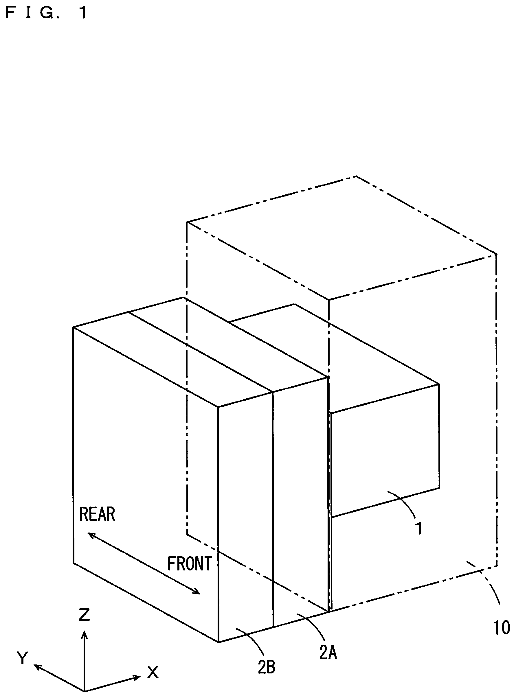
is a perspective view of an autosampler 1 and plate changers 2 A, 2 B according to this embodiment. In the following description, an X direction, a Y direction, and a Z direction shown in each of the drawings are referred to as appropriate. In to 12 , an XY plane corresponds to a horizontal plane, and the Z direction corresponds to a vertical direction. Also, in to 12 , description is made on a case where the X direction is a left-and-right direction and the Y direction is a front-and-rear direction as an example.
The autosampler 1 is incorporated as a unit in a liquid chromatograph 10 that is an analyzer of this embodiment. The liquid chromatograph 10 also includes other units such as a pump unit, a column oven unit and a detector unit. The autosampler 1 continuously supplies samples to an analysis flow path of the liquid chromatograph 10 .
The plate changers 2 A, 2 B each supply a plate storing the samples to the autosampler 1 . The samples are stored in sample bottles arranged in the plate. A large number of sample bottles can be arranged in the plate. Alternatively, the samples are stored in wells formed in the plate. A large number of wells can be formed in the plate. For example, 96 or 384 sample bottles are stored or wells are formed in the plate.
In this embodiment, as shown in , the autosampler 1 , the plate changer 2 A, and the plate changer 2 B are arranged to line up in an X axis direction (the left-and-right direction). That is, the autosampler 1 is arranged at one side (a right side) of the plate changer 2 A in the X axis direction, and the plate changer 2 B is arranged at another side (a left side) of the plate changer 2 A in the X axis direction.
is a plan view showing an internal structure of the autosampler 1 and the plate changers 2 A, 2 B according to this embodiment. is a functional block diagram of the autosampler 1 and the plate changers 2 A, 2 B according to this embodiment. As shown in , the autosampler 1 and the plate changers 2 A, 2 B are covered with casings. In , a ceiling surface of each casing is not shown to explain the internal structure of the autosampler 1 and the plate changers 2 A, 2 B.
As shown in , the autosampler 1 includes a needle driver 120 . The needle driver 120 includes a Y axis guide rail 121 , an X axis guide rail 122 , and a Z axis guide 123 . The Z axis guide 123 supports a needle not shown. The needle injects samples into the analysis flow path of the liquid chromatograph 10 . As shown in , the autosampler 1 includes a controller 11 .
The Y axis guide rail 121 extends in the Y axis direction. The X axis guide rail 122 extends in the X axis direction. The X axis guide rail 122 is movable in the Y axis direction along the Y axis guide rail 121 . The Z axis guide 123 is movable in the X axis direction along the X axis guide rail 122 . The Z axis guide 123 includes a driver that can advance and retreat in the Z axis direction. With this configuration, the controller 11 of the autosampler 1 moves the X axis guide rail 122 along the Y axis guide rail 121 , moves the Z axis guide 123 along the X axis guide rail 122 , and advances and retreats the driver of the Z axis guide 123 in the Z axis direction, so that the needle can be moved in three axis directions of the X, Y, and Z axes.
The controller 11 of the autosampler 1 performs control of the autosampler 1 . The controller 11 controls the X axis guide rail 122 , the Z axis guide 123 , and the driver of the Z axis guide to control an operation of the needle. The controller 11 moves the needle to a position of a plate 5 to cause the needle to suck the samples stored in the plate 5 . Also, the controller 11 moves the needle to an injection port of an analysis path to inject the samples sucked by the needle into the analysis path.
The controller 11 further includes a communication function. The controller 11 communicates with a system controller of the liquid chromatograph 10 . Thus, the controller 11 performs control of the autosampler 1 in accordance with instructions provided by the system controller. Also, the controller 11 performs control of the plate changers 2 A, 2 B by sending instructions to the plate changers 2 A, 2 B.
As shown in , the plate changers 2 A, 2 B include plate transporters 22 A, 22 B, respectively. The plate changers 2 A, 2 B also include racks 23 A, 23 B that store the plates 5 , respectively. In the example shown in , the racks 23 A, 23 B are respectively arranged in front sides of the plate changers 2 A, 2 B in the Y axis direction. As shown in , the plate changers 2 A, 2 B include controllers 21 A, 21 B, drivers 24 A, 24 B, and recognizers 25 A, 25 B, respectively.
The plate transporters 22 A, 22 B are devices that each holds and transports the plate 5 . The plate transporters 22 A, 22 B each hold the plate 5 by pinching the plate 5 with an arm. The plate changers 2 A, 2 B include the drivers 24 A, 24 B, respectively. With the drivers 24 A, 24 B driven, the plate transporters 22 A, 22 B each perform an advancing and retreating operation in the Y axis direction, a lifting and lowering operation in the Z axis direction, and a rotating operation in the XY plane. Also, with the drivers 24 A, 24 B driven, the plate transporters 22 A, 22 B each perform an operation of holding the plate 5 and an operation of releasing the plate 5 with the arm.
is a side view showing the internal structure of the plate changer 2 A ( 2 B). As shown in , the rack 23 A, 23 B includes a plurality of tiers of slots arranged in the Z axis direction (top-and-bottom direction), and each slot can store the plate 5 . For example, the rack 23 A, 23 B includes 14 tiers of slots in the Z axis direction (top-and-bottom direction) and can store 14 plates 5 .
The controllers 21 A, 21 B perform control of the plate changers 2 A, 2 B, respectively. The controllers 21 A, 21 B perform control of the drivers 24 A, 24 B and the recognizers 25 A, 25 B, respectively. The controllers 21 A, 21 B control the drivers 24 A, 24 B, so that the plate transporters 22 A, 22 B perform the advancing and retreating operation in the Y axis direction, the lifting and lowering operation in the Z axis direction, the rotating operation in the XY plane, and the operation of holding the plates 5 .
The recognizers 25 A, 25 B recognize the plates 5 stored in the racks 23 A, 23 B, respectively. An identifier that specifies a type of the plate 5 and contents of a sample stored in the plate 5 is displayed on the plate 5 . The recognizer 25 A, 25 B reads the identifier displayed on the plate 5 to acquire information as to the type of the plate 5 and the sample stored in the plate 5 . Examples of the types of the plate 5 include a microtiter plate with 96 wells, a microtiter plate with 384 wells, etc. The identifier is, for example, a color, a character, etc. A barcode may be utilized as the identifier. The recognizer 25 A, 25 B may be provided in the vicinity of each slot of the rack 23 A, 23 B. For example, when the rack 23 A, 23 B includes 14 tiers of slots, the recognizer 25 A, 25 B is provided at each slot. Alternatively, the recognizer 25 A, 25 B is provided at one place. In this case, the plate transporter 22 A, 22 B takes out the plate 5 from the rack 23 A, 23 B and transports the plate 5 to a position where the recognizer 25 A, 25 B can read the plate 5 .
The controller 21 A, 21 B includes a communication function. As shown in , the controller 11 of the autosampler 1 and the controller 21 A of the plate changer 2 A are connected by a communication line 31 . The controller 21 A of the plate changer 2 A and the controller 21 B of the plate changer 2 B are connected by a communication line 32 . In this way, the autosampler 1 , the plate changer 2 A, and the plate changer 2 B are daisy-chain-connected by the communication lines 31 , 32 .
(2) Operation of Liquid Chromatograph
Description will now be made on an operation of the liquid chromatograph 10 using the autosampler 1 and the plate changers 2 A, 2 B of this embodiment.
(2-1) Recognition of Plates
First, an operator prepares a plurality of plates 5 storing samples. As described above, the identifier that specifies the type of each plate 5 or the contents of the sample stored in each plate 5 is displayed on each plate 5 . The operator stores the prepared plates 5 in the racks 23 A, 23 B of the plate changers 2 A, 2 B. A plurality of insertion openings corresponding to the plurality of tiers of slots of the racks 23 A, 23 B are provided in the casings of the plate changers 2 A, 2 B. The operator inserts the prepared plurality of plates 5 from the plurality of insertion openings and stores each of the inserted plates 5 in each slot of the racks 23 A, 23 B. The operator may store each plate 5 in any slot of the racks 23 A, 23 B.
Then, the recognizers 25 A, 25 B of the plate changers 2 A, 2 B recognize the plates 5 stored in the racks 23 A, 23 B. The recognizers 25 A, 25 B supply recognition information of the plates 5 to the controllers 21 A, 21 B, respectively. The controllers 21 A, 21 B inform the controller 11 of the autosampler 1 of the recognition information via the communication lines 32 , 31 . By the foregoing operation, the controller 11 of the autosampler 1 and the controllers 21 A, 21 B of the plate changers 2 A, 2 B acquire the recognition information of the plates 5 .
(2-2) Supply of Plates to Autosampler
An operation of supplying the plates 5 to the autosampler 1 will now be described. First, the controller 11 of the autosampler 1 receives an instruction to designate a target plate 5 to be analyzed from the system controller of the liquid chromatograph 10 . Then, the controller 11 transmits an instruction to supply the plate 5 to the plate changer 2 A, 2 B storing the target plate 5 to be analyzed.
Here, a case in which the target plate 5 is stored in the rack 23 B of the plate changer 2 B will be described as an example. The controller 11 of the autosampler 1 transmits an instruction to supply the plate 5 , a destination of which is the plate changer 2 B. The supply instruction is received at the controller 21 A of the plate changer 2 A via the communication line 31 and received at the controller 21 B of the plate changer 2 B via the communication lines 31 , 32 . The controller 21 A confirms that the destination of the supply instruction is not the plate changer 2 A of itself. The controller 21 B confirms that the destination of the supply instruction is the plate changer 2 B of itself. The supply instruction transmitted from the controller 11 includes information that specifies the target plate 5 . The controller 21 B specifies a slot of the rack 23 B in which the target plate 5 is stored.
The controller 21 B supplies an instruction to transport the target plate 5 to the driver 24 B. The driver 24 B drives the plate transporter 22 B to move to the slot storing the target plate 5 . is a diagram for explaining the operation of the plate changers 2 A, 2 B and showing a state where the plate transporter 22 B moves to the slot of the rack 23 B storing the target plate 5 . The plate transporter 22 B first moves to a level of the slot storing the target plate 5 in the Z axis direction. The plate transporter 22 B then moves forward in the Y axis direction and moves to a position where the plate transporter 22 B pinches the target plate 5 with the arm, as shown in . Subsequently, the plate transporter 22 B performs an operation of closing the arm to hold the target plate 5 . For example, in a case where the target plate 5 is stored in a slot on the tenth tier from the bottom, the plate transporter 22 B first moves in the top-and-bottom direction (Z axis direction) to a position of the slot on the tenth tier. Subsequently, the plate transporter 22 B moves forward in the Y axis direction to hold the plate 5 .
In , the controller 11 of the autosampler 1 provides a retracting instruction to the plate transporter 22 A before the plate transporter 22 B starts the operation of holding the target plate 5 or while the plate transporter 22 B performs the holding operation. The retracting instruction is an instruction to retract the plate transporter 22 A to a level at which the plate transporter 22 A does not interfere with a transfer operation so as to prevent the plate transporter 22 A from interfering with the plate transporter 22 B and the plate 5 held by the plate transporter 22 B.
In this embodiment, it is positions of bottom plates in the casings of the plate changers 2 A, 2 B that the plate transporter 22 B performs the operation of transferring the plate 5 to the plate changer 2 A. As shown in , a transfer stage 41 is provided at the positions of the bottom plates in the casings of the plate changers 2 A, 2 B in a manner that the transfer stage 41 bridges across the bottom plates of the both casings. In the casings of the plate changers 2 A, 2 B, a transfer window 42 is formed at the place where the transfer stage 41 is arranged. That is, the plate changers 2 A, 2 B are connected at the transfer window 42 . Thus, when the plate transporter 22 A is at a position corresponding to a slot on the lowest tier of the rack 23 A, the plate transporter 22 A moves upward (in the Z axis direction) and retracts so as not to interfere with the transfer operation by the plate transporter 22 B. For example, the plate transporter 22 A rises to a position between the slot on the lowest tier and a slot on the second tier from the bottom. The position at this level is a retracting position. In , the plate transporter 22 A is denoted with a two-dot and dash line, which indicates that the plate transporter 22 A is at the retracting position.
Then, the controller 21 B drives the driver 24 B to move the plate transporter 22 B backward in the Y axis direction. Thus, the plate transporter 22 B moves away from the rack 23 B while holding the plate 5 , and returns to a rear position in the plate changer 2 B as shown in . Subsequently, the controller 21 B controls the driver 24 B to lower the plate transporter 22 B to the position where the transfer stage 41 is located. is a diagram for explaining the operation of the plate changers 2 A, 2 B and showing a state where the plate transporter 22 B is lowered to the position where the transfer stage 41 is located at the rear position. For example, in a case where the plate 5 taken out by the plate transporter 22 B is stored in the slot on the tenth tier from the bottom, the plate transporter 22 B holds the plate 5 at the position of the tenth tier from the bottom and then returns to the rear position, and is subsequently lowered from the tenth tier to the position where the transfer stage 41 is located. In , the plate transporter 22 A waits at the level of the retracting position.
Then, the controller 21 B controls the driver 24 B to rotate the plate transporter 22 B in the XY plane. is a diagram for explaining the operation of the plate changers 2 A, 2 B and showing a state where the plate changer 2 B is rotated counterclockwise by 90 degree at the position where the transfer stage 41 is located. Then, the controller 21 B controls the driver 24 B to widen a spacing of the arm of the plate transporter 22 B to release the plate 5 . Thus, the plate 5 is placed on the transfer stage 41 .
Then, the controller 21 B controls the driver 24 B to raise the plate transporter 22 B by a predetermined height and then rotate the plate transporter 22 B clockwise by 90 degree. Thus, the plate transporter 22 B returns into the plate changer 2 B without interfering with the plate 5 with the level of the plate transporter 22 B deviated from that of the plate 5 . Further, the controller 21 B controls the driver 24 B to raise the plate transporter 22 B to the level of the retracting position.
Then, the controller 11 of the autosampler 1 sends an instruction to receive the plate 5 to the controller 21 A of the plate changer 2 A. In response to this instruction, the controller 21 A first controls the driver 24 A to lower the plate transporter 22 A to the position deviated from the level of the plate 5 . Subsequently, the controller 21 A rotates the plate transporter 22 A clockwise by 90 degree. Then, the controller 21 A controls the driver 24 A to lower the plate transporter 22 A to the position of the transfer stage 41 . The controller 21 A subsequently controls the driver 24 A to narrow the spacing of the arm of the plate transporter 22 A to make the plate transporter 22 A hold the plate 5 . is a diagram for explaining the operation of the plate changers 2 A, 2 B and showing a state where the plate transporter 22 A holds the plate 5 at the position of the transfer stage 41 . In , the plate transporter 22 B is denoted with a two-dot and dash line, which indicates that the plate transporter 22 B is at the level of the retracting position.
Then, the controller 21 A controls the driver 24 A to rotate the plate transporter 22 A counterclockwise by 90 degree. Thus, the plate transporter 22 A returns into the plate changer 2 A while holding the plate 5 . is a diagram for explaining the operation of the plate changers 2 A, 2 B and showing a state where the plate transporter 22 A returns into the plate changer 2 A while holding the plate 5 .
Subsequently, the controller 21 A controls the driver 24 A to raise the plate transporter 22 A to a level of an analysis plate stage 43 in the autosampler 1 . In this embodiment, the analysis plate stage 43 shown in is at a level of a slot on the fifth tier from the bottom in the plate changer 2 A. Thus, the plate transporter 22 A rises to the level of the slot on the fifth tier from the bottom. A window 44 is provided on side surfaces of the casings of the plate changer 2 A and the autosampler 1 . The plate changer 2 A and the autosampler 1 are connected at the window 44 .
Then, the controller 21 A controls the driver 24 A to rotate the plate transporter 22 A counterclockwise by 90 degree. Further, the controller 21 A controls the driver 24 A to move the plate transporter 22 A in a right direction (a direction toward the autosampler 1 in the X axis direction). is a diagram for explaining the operation of the plate changers 2 A, 2 B and showing a state where the plate transporter 22 A moves into the autosampler 1 while holding the plate 5 . As described above, the driver 24 A of the plate transporter 22 A includes a driver that can advance and retreat in the Y axis direction. In the operation shown in , since the plate transporter 22 A is rotated by 90 degree, the plate transporter 22 A can advance and retreat in the X axis direction by driving of the driver 24 .
Subsequently, the controller 21 A controls the driver 24 A to widen the spacing of the arm of the plate transporter 22 A to make the plate transporter 22 A release the plate 5 . Thus, the plate 5 is placed on the analysis plate stage 43 . Then, the controller 21 A controls the driver 24 A to raise the plate transporter 22 A by a predetermined height so as not to interfere with the plate 5 , and then move the plate transporter 22 A in a left direction (a direction farther away from the autosampler 1 in the X axis direction). Further, the controller 21 A controls the driver 24 A to rotate the plate transporter 22 A clockwise by 90 degree. Thus, the plate transporter 22 A returns into the plate changer 2 A with the level of the plate transporter 22 A deviated from that of the plate 5 . Finally, the controller 11 of the autosampler 1 instructs the controller 21 A of the plate changer 2 A and the controller 21 B of the plate changer 2 B to move to a standby position. The controllers 21 A and 21 B control the drivers 24 A and 24 B to lower and move the plate transporters 22 A, 22 B to the standby positions, respectively. is a diagram for explaining the operation of the plate changers 2 A, 2 B and showing a state where the plate 5 is placed on the analysis plate stage 43 and the plate transporters 22 A, 22 B are positioned at the standby positions.
By the foregoing operations, the plate 5 stored in the rack 23 B of the plate changer 2 B is transported to the analysis plate stage 43 of the autosampler 1 via the plate changer 2 A. The controller 11 of the autosampler 1 moves the needle to suck the sample from the plate 5 placed on the analysis plate stage 43 and inject the sucked sample into the analysis path.
As has been described above, the plate changers 2 A, 2 B of this embodiment can supply the plate 5 to the autosampler 1 by transferring the plate 5 between the plate changers 2 A and 2 B. Thus, it is possible to flexibly deal with the number of plates 5 that can be supplied to the autosampler 1 according to the user's needs by increasing or decreasing the number of the plate changers to be connected. Since a combination of the plate changers having the common structure can be utilized, a manufacturing cost for such plate changers can be reduced compared to a cost required to individually manufacture the plate changers according to the number of plates.
(2-3) Collection of Plates from Autosampler
When analysis processing on the plate 5 transported to the analysis plate stage 43 is completed, the plate 5 is returned to the rack 23 B of the plate changer 2 B. This operation is opposite to the operation of “(2-2) Supply of Plates to Autosampler” as described above.
First, the plate transporter 22 A rotates counterclockwise by 90 degree at the level of the analysis plate stage 43 in the autosampler 1 and moves into the autosampler 1 . Then, the plate transporter 22 A is lowered to a predetermined level and holds the plate 5 placed on the analysis plate stage 43 . Subsequently, the plate transporter 22 A rises to the level of the analysis plate stage 43 in the autosampler 1 again, and then rotates clockwise by 90 degree and returns into the plate changer 2 A.
Subsequently, the plate transporter 22 A is lowered from the level of the analysis plate stage 43 in the autosampler 1 to the position of the transfer stage 41 . Then, the plate transporter 22 A rotates clockwise by 90 degree and transports the plate 5 to the position of the transfer stage 41 . At this time, the plate transporter 22 B waits at the retracting position. Then, the plate transporter 22 A opens the arm to release the plate 5 . The plate transporter 22 A then rises by a predetermined height and rotates counterclockwise by 90 degree while avoiding the interference with the plate 5 . Thus, the plate 5 is placed on the transfer stage 41 .
Subsequently, the plate transporter 22 B is lowered to a position above the transfer stage 41 by a predetermined height so as not to interfere with the plate 5 , and rotates counterclockwise by 90 degree. Then, the plate transporter 22 B is lowered to the position of the transfer stage 41 to hold the plate 5 . The plate transporter 22 B subsequently rises by a predetermined height and rotates clockwise by 90 degree while holding the plate 5 . Finally, the plate transporter 22 B moves to the level of the slot storing the plate 5 and stores the plate 5 . In the above-described example, the plate transporter 22 B rises to the level of the slot on the tenth tier and moves forward in the Y axis direction. Then, the plate transporter 22 B stores the plate 5 in the slot on the tenth tier.
(2-4) Other Operations
In the above-described operation example described in “(2-2) Supply of Plates to Autosampler,” the case where the plate changer 2 A receives the plate 5 from the plate changer 2 B and transfers the plate 5 to the autosampler 1 is described as the example. In a case where the destination of the supply instruction received from the controller 11 of the autosampler 1 is the plate changer 2 A, that is, in a case where the target plate 5 to be analyzed is stored in the rack 23 A, the plate changer 2 A takes out the plate 5 from the rack 23 A and transfers the plate 5 to the autosampler 1 . In other words, in the above-described example of the operation of “(2-2) Supply of Plates to Autosampler,” the plate transporter 22 A receives the plate 5 from the transfer stage 41 and transfers the plate 5 to the analysis plate stage 43 of the autosampler 1 . In the case where the destination of the supply instruction is the plate changer 2 A, the controller 21 A performs control of specifying the target plate 5 included in the supply instruction, taking out the plate 5 from the rack 23 A, and transporting the plate 5 to the analysis plate stage 43 .
In the above-described operation example described in “(2-3) Collection of Plates from Autosampler,” the case where the plate changer 2 A receives the plate 5 from the autosampler 1 and transfers the plate 5 to the plate changer 2 B is described as the example. In a case where the destination of the supply instruction received from the controller 11 of the autosampler 1 is the plate changer 2 A, the plate changer 2 A stores the plate 5 collected from the autosampler 1 in the rack 23 A. In other words, in the above-described example of the operation of “(2-3) Collection of Plates from Autosampler,” the plate transporter 22 A receives the plate 5 from the analysis plate stage 43 of the autosampler 1 and transfers the plate 5 to the transfer stage 41 . In a case where a return destination of the target plate 5 is the rack 23 A of the plate changer 2 A, the controller 21 A performs control of collecting the plate 5 from the analysis plate stage 43 and storing the plate 5 in the original slot of the rack 23 A.
(3) Other Connection Forms
In the above-described embodiment, the description is made on the case where the two plate changers 2 A, 2 B are connected at the side of the autosampler 1 . The number of plate changers connected to the autosampler is not particularly limited. For example, a larger number of plate changers such as three, four, and so on may be connected.
is a diagram showing an embodiment in which three plate changers 2 A, 2 B, and 2 C are connected. That is, the plate changer 2 C is additionally provided between the plate changer 2 A and the autosampler 1 in the embodiment shown in , 2 , etc. In this case, the plate 5 stored in the rack 23 B of the plate changer 2 B is transported in order from the plate changer 2 B through the plate changer 2 A and the plate changer 2 C to the autosampler 1 , and then placed on the analysis plate stage 43 . When analysis processing is completed, the plate 5 is transported from the autosampler 1 through the plate changer 2 C and the plate changer 2 A to the plate changer 2 B and then stored in the original slot in the rack 23 B.
An operation in a case where a larger number of plate changers such as four, five, and so on are connected is similar. Each plate changer receives a target plate 5 to be analyzed from a plate changer at a preceding position and transfers the plate 5 to a plate changer at a succeeding position. A plate changer at a most-succeeding position (a plate changer closest to the autosampler 1 ) transfers the received plate to the autosampler 1 . Also, each plate changer receives the analyzed plate 5 from the plate changer at the succeeding position and transfers the received plate 5 to the plate changer at the preceding position or stores the received plate 5 in the rack of the plate changer itself. Also in the case where three or more plate changers are connected, the autosampler 1 and the controllers of the plurality of plate changers are daisy-chain-connected similarly to the above-described embodiment.
In the above-described embodiment, the description is made on the case where the two plate changers 2 A, 2 B are connected at the side of the autosampler 1 . That is, the different plate changer 2 B is connected at the preceding position of the plate changer 2 A. As another example, a preprocessor for a sample may be connected at the preceding position of the plate changer 2 A.
is a diagram showing an embodiment in which the plate changer 2 A and a preprocessor 6 are connected. That is, the preprocessor 6 is additionally attached to the preceding position of the plate changer 2 A in place of the plate changer 2 B in the embodiment shown in , 2 , etc.
The preprocessor 6 performs processing such as processing of removing components contained in a sample that are unnecessary for analysis processing, processing of labeling a specific component, or processing of extracting the specific component. When the preprocessor 6 completes preprocessing to the sample, the preprocessor 6 places the plate storing the sample on the transfer stage similarly to the above-described plate changer 2 B. That is, the preprocessor 6 places the plate 5 , in which the preprocessed sample is stored, on the transfer stage. The plate changer 2 A receives the plate 5 placed on the transfer stage and supplies the received plate 5 to the autosampler 1 . The transfer stage is provided to bridge across in the casings of the preprocessor 6 and the plate changer 2 A.
In this case, the plate 5 preprocessed in the preprocessor 6 is transported in order from the preprocessor 6 through the plate changer 2 A to the autosampler 1 and then placed on the analysis plate stage 43 .
The preprocessor 6 may be arranged at a most-preceding stage (a position farthest from the autosampler 1 ). For example, in a case where a large number of plate changers such as three, four, and so on are connected, the preprocessor 6 is connected at the preceding stage of the plate changer at the most-preceding stage. The plate 5 preprocessed in the preprocessor 6 is transferred in order among the plate changers and then supplied to the autosampler 1 .
In the above-described embodiment, the description is made on the case where the plate changers 2 A, 2 B supply the plate storing the sample to the liquid chromatograph 10 . The plate changers 2 A, 2 B of this embodiment can also be used in another apparatus such as a gas chromatograph other than the liquid chromatograph.
The specific configuration of the present invention is not limited to the above-described embodiments, and various variations and modifications may be made without departing the scope of the present invention.
(4) Correspondences Between Constituent Elements in Claims and Parts in Embodiments
While examples of correspondences between constituent elements in claims below and parts in the embodiments are explained in the following paragraphs, the present invention is not limited to the examples below. In the above-described embodiments, the liquid chromatograph 10 is an example of an analyzer. Also, in the above-described embodiments, the plate changer 2 A is an example of a plate changer in the claims, and the plate changer 2 B is an example of a first plate changer. Further, in the above-described embodiments, the plate changer 2 C is an example of a second plate changer. Moreover, in the above-described embodiments, the rack 23 A is an example of a storage.
As each of various elements recited in the claims, various other elements having configurations or functions described in the claims can be also used.
(5) Aspects
The above-mentioned plurality of exemplary embodiments are understood as specific examples of the below-mentioned aspects by those skilled in the art.
(Item 1) A plate changer according to one aspect is a plate changer that supplies a plate storing a sample to an autosampler included in an analyzer and includes:
•
• a storage that stores the plate; and • a plate transporter that transports the plate by holding the plate, and • the plate transporter receives the plate from a first plate changer provided at one side of the plate changer and also transfers the plate received from the first plate changer to a second plate changer or the autosampler provided at another side of the plate changer or transfers the plate stored in the storage to the second plate changer or the autosampler.
The plate changer of this embodiment can supply the plate to the autosampler by transferring the plate among the plate changers. This makes it possible to flexibly deal with the number of plates that can be supplied to the autosampler according to a user's needs.
(Item 2) In the plate changer according to item 1,
•
• the plate transporter may receive the plate from the second plate changer or the autosampler and also transfer the plate received from the second plate changer or the autosampler to the first plate changer or store the plate received from the second plate changer or the autosampler into the storage.
The plate changer of this embodiment can collect the plate from the autosampler by transferring the plate among the plate changers. This makes it possible to flexibly deal with the number of plates that can be supplied to the autosampler according to the user's needs.
(Item 3) In the plate changer according to item 1,
•
• the plate transporter may receive the plate from a preprocessor for a sample provided at one side of the plate changer and also transfer the plate received from the preprocessor to the second plate changer or the autosampler.
The plate changer of this embodiment can supply the plate to the autosampler by transferring the plate among the preprocessor and the plate changers.
(Item 4) In the plate changer according to item 1,
•
• when the plate is transported from the first plate changer to a transfer place where the plate is transferred to the plate transporter, the plate transporter may retract in a top-and-bottom direction in the plate changer so as not to interfere with a transport operation of transporting the plate to the transfer place.
It is possible to make smaller a space required for a transfer operation of transferring the plate.
(Item 5) In the plate changer according to item 4,
•
• the plate may be placed on a transfer stage provided at the transfer place by the transport operation, and the plate transporter may hold the plate placed on the transfer stage.
The transfer of the plate among the plate changers is carried out through the transfer stage. The number of plate changers can be easily increased.
(Item 6) In the plate changer according to item 5,
•
• the transfer stage may be provided to bridge across in a casing of the plate changer and in a casing of the first plate changer.
The transfer operation of transferring the plate is easily performed among the plate changers.
(Item 7) In the plate changer according to claim 1 ,
•
• a communication line among the first plate changer, the plate changer, and the second plate changer or a communication line among the first plate changer, the plate changer, and the autosampler may be daisy-chain-connected.
Wiring of the communication lines connecting the plate changers is simplified. Complication of wiring around the analyzer can be avoided.
Figures (13)
Citations
This patent cites (1)
- US2006189362