Air Conditioner That Defrosts Outdoor Heat Exchanger Based on Refrigerant Residue Amount of Outdoor Heat Exchanger
Abstract
An air conditioner includes an indoor unit, an outdoor unit, and a controller. The controller of an air conditioner switches between a first defrosting drive to defrost a first outdoor heat exchanger and a second outdoor heat exchanger at the same time, and a second defrosting drive to defrost the first outdoor heat exchanger after the start of defrosting of the second outdoor heat exchanger; estimates a refrigerant residue amount of the first outdoor heat exchanger and a refrigerant residue amount of the second outdoor heat exchanger; and adjusts an opening degree of the first expansion valve and an opening degree of the second expansion valve, based on the refrigerant residue amount of the first outdoor heat exchanger and the refrigerant residue amount of the second outdoor heat exchanger.
Claims (3)
1. An air conditioner in which an indoor unit and an outdoor unit are connected by a pipe, and a temperature of a space where the indoor unit is disposed is conditioned, the air conditioner comprising: a controller configured to control the indoor unit and the outdoor unit, wherein the outdoor unit includes a first outdoor heat exchanger configured to exchange heat of a temperature of a refrigerant flowing from the pipe with an outside air, a second outdoor heat exchanger configured to exchange heat of the temperature of the refrigerant flowing from the pipe with the outside air, the second outdoor heat exchanger disposed below the first outdoor heat exchanger, a first expansion valve configured to adjust a flow rate of the refrigerant flowing from the first outdoor heat exchanger to the pipe, a second expansion valve configured to adjust a flow rate of the refrigerant flowing from the second outdoor heat exchanger to the pipe, an outside air temperature sensor configured to acquire a temperature of outside air, a first outdoor heat exchanger temperature sensor configured to acquire a temperature of the first outdoor heat exchanger, a first refrigerant temperature sensor configured to acquire a temperature of the refrigerant flowing from the first expansion valve to the pipe, a second outdoor heat exchanger temperature sensor configured to acquire a temperature of the second outdoor heat exchanger, and a second refrigerant temperature sensor configured to acquire a temperature of the refrigerant flowing from the second expansion valve to the pipe, and the controller varies an opening degree of the first expansion valve and an opening degree of the second expansion valve to be equal to or less than a predetermined opening degree based on the temperature acquired by the outside air temperature sensor and switches between a first defrosting drive to defrost the first outdoor heat exchanger and the second outdoor heat exchanger at the same time, and a second defrosting drive to defrost the first outdoor heat exchanger after the start of defrosting of the second outdoor heat exchanger; estimates a refrigerant residue amount of the first outdoor heat exchanger based on the temperatures acquired by the first outdoor heat exchanger temperature sensor and the first refrigerant temperature sensor, and a refrigerant residue amount of the second outdoor heat exchanger based on the temperatures acquired by the second outdoor heat exchanger temperature sensor and the second refrigerant temperature sensor; and adjusts the opening degree of the first expansion valve configured to adjust the flow rate of the refrigerant flowing from the first outdoor heat exchanger before defrosting to the pipe and the opening degree of the second expansion valve configured to adjust the flow rate of the refrigerant flowing from the second outdoor heat exchanger before defrosting to the pipe, based on the refrigerant residue amount of the first outdoor heat exchanger and the refrigerant residue amount of the second outdoor heat exchanger.
Show 2 dependent claims
2. The air conditioner of claim 1 , wherein when the controller defrosts the first outdoor heat exchanger after the start of defrosting of the second outdoor heat exchanger, the controller sets the opening degree of the first expansion valve to be equal to or less than the predetermined opening degree which is below a fully opening degree and defrosts the second outdoor heat exchanger, and sets the opening degree of the second expansion valve to be equal to or less than the predetermined opening degree which is below the fully opening degree and defrosts the first outdoor heat exchanger.
3. The air conditioner of claim 1 , wherein the controller varies, if the first outdoor heat exchanger and the second outdoor heat exchanger are not in a defrost condition, and the temperature acquired by the outside air temperature sensor satisfies a certain condition, the opening degrees of the first and second expansion valves to be equal to or less than a fully opening degree.
Full Description
Show full text →
CROSS-REFERENCE TO RELATED APPLICATIONS
This application is a Continuation Application of PCT Application No. PCT/JP2020/035357, filed Sep. 17, 2020, the entire contents of which are incorporated herein by reference.
FIELD
Embodiments described herein relate generally to an air conditioner.
BACKGROUND
For air conditioner with two outdoor heat exchangers, there is a known technique of a defrosting control in a heating operation in which the two outdoor heat exchangers are defrosted at the same time.
In the aforementioned technique, when an outside air temperature is very low, a part of an outdoor unit where is relatively easy to be cold, for example, drain water residue in the lower part of the outdoor unit may be frozen. In such a case, if the heating drive is continued for a long time, the freezing of drain water progresses, and the freezing is nor solved even after a defrosting drive. Furthermore, the residual ice may prevent discharge of drain water newly produced, and a drain water residue amount in a frost receiver (bottom plate) increases, and accordingly, more drain water tends to freeze, which is a vicious cycle.
BRIEF DESCRIPTION OF THE DRAWINGS
is a diagram illustrating an example of the structure of an air conditioner.
is a timing chart illustrating a control of defrosting drive in a heating drive.
is a diagram illustrating an example of the structure of an air conditioner.
illustrates an example of a relationship between a temperature detected by an outside air temperature sensor and an opening degree of an expansion valve.
is a diagram illustrating an example where an expansion valve of an outdoor heat exchanger before defrosting is closed.
is a diagram illustrating an example where the expansion valve of the outdoor heat exchanger before defrosting is opened.
illustrates an example of the structure of an air conditioner.
illustrates an example of a relationship between a temperature detected by the outside air temperature sensor and an opening degree of the expansion valve.
is a diagram illustrating a refrigerant residue amount in the outdoor heat exchanger during the defrosting of the outdoor heat exchanger.
is a diagram illustrating adjustment of the opening degree of the expansion valve according to the refrigerant residue amount.
DETAILED DESCRIPTION
In general, according to one embodiment, an air conditioner includes an indoor unit, an outdoor unit, and a controller. The air conditioner is conditioned a temperature of a space where the indoor unit is disposed. The indoor unit and the outdoor unit are connected by a pipe. The controller is configured to control the indoor unit and the outdoor unit. The outdoor unit includes a first outdoor heat exchanger configured to exchange heat of a temperature of a medium flowing from the pipe with an outside air, and a second outdoor heat exchanger configured to exchange heat of the temperature of the medium flowing from the pipe with the outside air, the second outdoor heat exchanger disposed below the first outdoor heat exchanger. The controller includes a first defrost means and a second defrost means. The first defrost means is configured to defrost the first outdoor heat exchanger and the second outdoor heat exchanger at the same time. The second defrost means is configured to start defrosting of the second outdoor heat exchanger in advance, and to perform defrosting of the first outdoor heat exchanger after the start of defrosting of the second outdoor heat exchanger.
First Embodiment
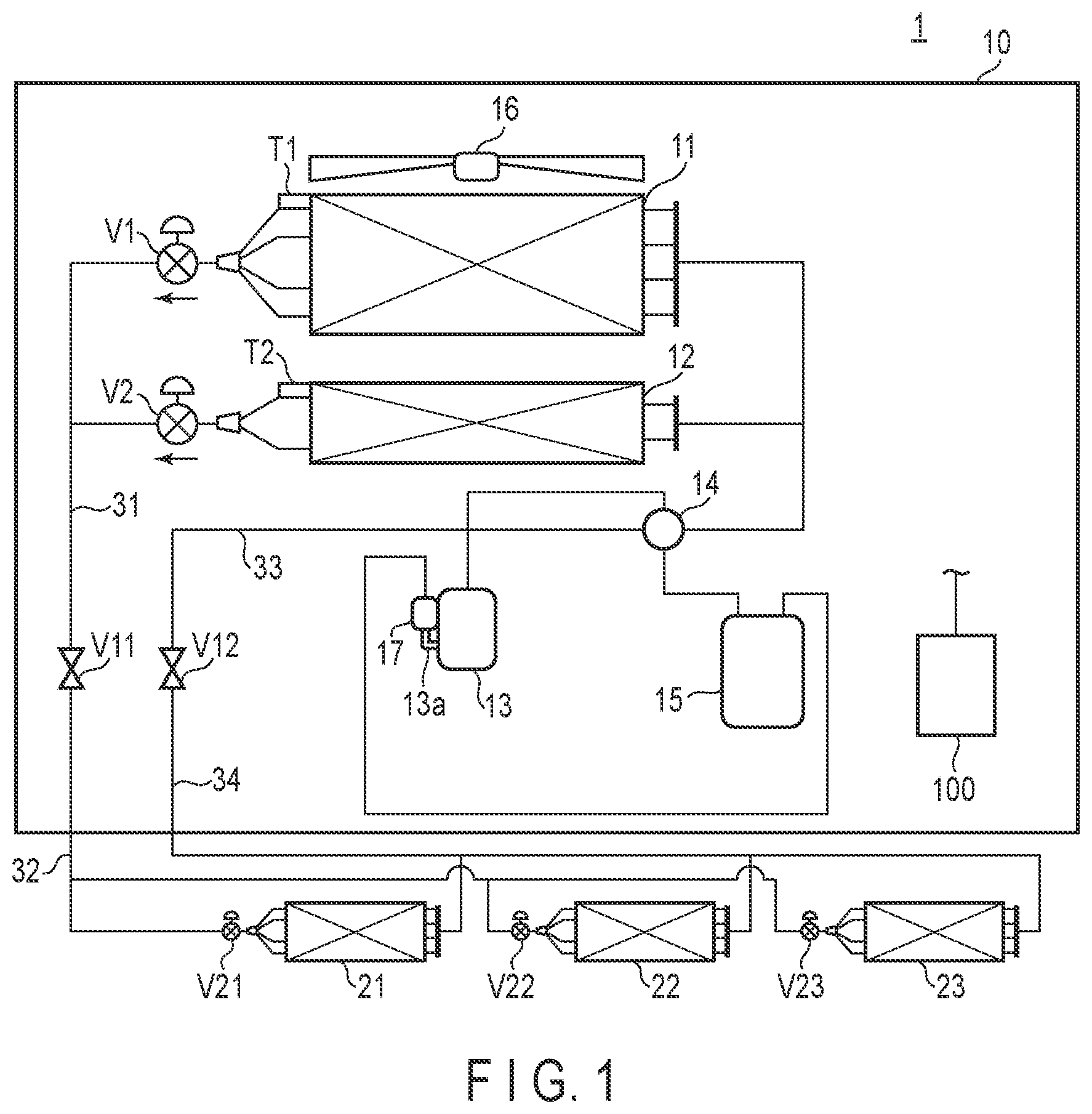
is a diagram illustrating an example of the structure of an air conditioner 1 .
As in , the air conditioner 1 includes an outdoor unit 10 with an outdoor heat exchanger (first outdoor heat exchanger) 11 , outdoor heat exchanger (second outdoor heat exchanger) 12 , which is disposed in the lower side of the outdoor heat exchanger 11 and has a heat exchanging performance which is lower than the outdoor heat exchanger 11 , compressor 13 , four-way valve 14 , and accumulator 15 , a plurality of indoor units 21 , 22 , and 23 , pipes 31 , 32 , 33 , and 34 connecting between the outdoor unit 10 and the indoor units 21 , 22 , and 23 , and a controller configured to control the outdoor unit 10 and the indoor units 21 , 22 , and 23 . The controller 100 is provided with the outdoor unit 10 in this example; however, the controller 100 and the outdoor unit 10 may be separated.
The outdoor heat exchangers 11 and 12 are, for example, fin tube type outdoor heat exchangers. Furthermore, an outdoor fan 16 is disposed to be opposed to the outdoor heat exchanger 11 . For example, the outdoor fan 16 is an axial flow fan. The compressor 13 can change drive frequency by a publically-known inverter control. A suction cup 17 , which is a relatively small gas/liquid separator, is provided with an intake port 13 a of the compressor 13 . Publically-known structures are used for the four-way valve 14 and the accumulator 15 .
The outdoor unit 10 and the indoor units 21 , 22 , and 23 are connected through the pipes 31 , 32 , 33 , and 34 . Specifically, one end of each of the outdoor heat exchangers 11 and 12 are connected to the pipe 31 , one end of each of the indoor units 21 , 22 , and 23 is connected to the pipe 32 , and the pipes 31 and 32 are connected together through a valve V 11 . Furthermore, the other end of each of the outdoor heat exchangers 11 and 12 is connected to the pipe 33 , the other end of each of the indoor units 21 , 22 , and 23 is connected to the pipe 34 , and the pipes 33 and 34 are connected together through a valve 12 . A refrigerant as a medium flows through the pipes 31 , 32 , 33 , and 34 . Note that, the compressor 13 , four-way valve 14 , accumulator 15 , and suction cup 17 are provided with the passage of the pipe 33 .
The air conditioner 1 with the aforementioned structure can perform heating or cooling to adjust a temperature of a space where the indoor units 21 , 22 , and 23 are arranged to a target temperature.
Furthermore, in the outdoor unit 10 , an expansion valve V 1 is disposed between the outdoor heat exchanger 11 and the pipe 31 , and an expansion valve V 2 is disposed between the outdoor heat exchanger 12 and the pipe 31 . The expansion valves V 1 and V 2 adjust a flow rate of the refrigerant (medium) flowing from the outdoor heat exchangers 11 and 12 to the pipes. An opening degree of each of the expansion valves V 1 and V 2 is determined based on commands from the controller 100 . That is, the controller 100 is configured to adjust the expansion valves V 1 and V 2 .
Furthermore, a temperature sensor T 1 is provided with the outdoor heat exchanger 11 for detecting a temperature of the outdoor heat exchanger 11 . Furthermore, a temperature sensor T 2 is provided with the outdoor heat exchanger 12 for detecting a temperature of the outdoor heat exchanger 12 . The temperature sensors T 1 and T 2 are disposed between the outdoor heat exchanges 11 and 12 and the expansion valves V 1 and V 2 , respectively, in the passage of the refrigerant flowing from the outdoor heat exchangers 11 and 12 to the pipe 31 . The temperatures detected are transmitted to the controller 100 .
The controller 100 includes a calculation circuit, a memory, and the like, which are not shown. The memory stores a control program, and various data. The controller 100 executes the control program stored in the memory to perform a defrosting drive of the outdoor heat exchangers 11 and 12 in the heating drive. In the present embodiment, at a time when switching the four-way valve 14 , first defrost means and second defrost means are executed as the defrosting drive in the heating drive.
The first defrost means is a means used for defrosting the outdoor heat exchangers 11 and 12 at the same time. The second defrost means is a means used for defrosting the outdoor heat exchanger 12 in advance, and defrosting the outdoor heat exchanger 11 after the start of defrosting of the outdoor heat exchanger 12 .
Specifically, the second defrost means is started once in a few operations of the first defrost means which defrosts the outdoor heat exchangers 11 and 12 when the four-way valve 14 is switched according to the defrost control in the heating drive of the air conditioner 1 , and the second defrost means narrows the opening degree of the expansion valve V 1 between 0 and 50% of the fully opening degree, and sets the opening degree of the expansion valve V 2 between 50 and 100% of the fully opening degree in order to end the defrosting of the outdoor heat exchanger 12 , and then, while maintaining the opening degree of the expansion valve V 2 , sets the opening degree of the expansion valve V 1 between 50 and 100% of the fully opening degree in order to perform defrosting of the outdoor heat exchanger 11 . Thus, drain water of the outdoor heat exchanger 11 can be heated by the outdoor heat exchanger 12 after the defrosting, and thereby, an icicle growth can be suppressed.
is a timing chart illustrating the control of defrosting drive in the heating drive.
As in , in a defrosting drive D 1 (first defrost means), when the defrosting is started, both the expansion valves V 1 and V 2 are fully opening, and thus, the temperatures detected by the temperature sensors T 1 and T 2 start to increase. If a defrosting end threshold is satisfied for a certain period in each of the outdoor heat exchangers 11 and 12 , the defrosting drive ends, and each of the expansion valves V 1 and V 2 starts to close to a predetermined minimal opening degree.
In contrast, in a defrosting drive D 2 (second defrost means), when the defrosting is started, only the expansion valve V 2 is fully opened (and 0 to 20% in the expansion valve V 1 ), and through the defrosting drive, the temperature of the temperature sensor T 2 is increased. If the outdoor heat exchanger 12 satisfies the defrosting end threshold for a predetermined period and the defrosting of the outdoor heat exchanger 12 ends, the expansion valve V 1 is fully opened, and the defrosting of the outdoor heat exchanger 11 is started, through the defrosting drive, the temperature of the temperature sensor T 1 is increased. If the outdoor heat exchanger 11 satisfies the defrosting end threshold for a predetermined period and the defrosting of the outdoor heat exchanger 11 is finished, after all the defrosting is finished, the expansion valves V 1 and V 2 are closed to the predetermined minimal opening degree. The temperature of drain water is, as shown in the lower side of , higher in the defrosting drive D 2 than the defrosting drive D 1 .
The air conditioner 1 structured as above can start defrosting of the outdoor heat exchanger 12 in advance and then perform defrosting of the outdoor heat exchanger 11 after the start of defrosting of the outdoor heat exchanger 12 . Thus, the air conditioner 1 can heat the drain water of the outdoor heat exchanger 11 with the outdoor heat exchanger 12 after the defrosting such that growth of ice (icicle) is suppressed.
Furthermore, the air conditioner 1 adjusts the opening degrees of the expansion valves V 1 and V 2 in order to shift times to start the defrosting of the outdoor heat exchangers 11 and 12 . Thus, the air conditioner 1 can suppress the growth of icicle cost effectively for not using additional actuator or circuit.
Furthermore, the air conditioner 1 may include an outside air temperature sensor configured to detect an outside air temperature in order to switch between the first defrost means and the second defrost means according to the temperature detected by the outside air temperature sensor. For example, if the outside air temperature is a temperature by which ice (icicle) does not grow, the controller 100 can use only the first defrost means for defrosting the outdoor heat exchangers 11 and 12 at the same time in order to shorten the defrosting time in the air conditioner 1 .
Second Embodiment
In the aforementioned second defrost means, the outdoor heat exchanger 12 in the lower row is first defrosted such that draining is performable while a condensation temperature and an outdoor heat exchanger temperature in the defrosting drive are high, and furthermore, the outdoor heat exchanger 11 in the upper row is then defrosted while the temperature of the outdoor heat exchanger 12 in the lower row is increased, and thus, the drain temperature is increased such that the icicle growth can be suppressed. However, when the expansion valve V 1 in the outdoor heat exchanger 11 before the defrosting, or the expansion valve V 2 of the outdoor heat exchanger 12 is closed, the refrigerant resides in the outdoor heat exchanger 11 and 12 , density inside the pipe 33 may be lowered, and low circulation of refrigerant may possibly occur. In the second embodiment, the air conditioner 1 which can avoid such a case will be explained. Note that, the same elements as in the first embodiment will be referred to by the same reference numbers, and the detailed explanation thereof will be omitted.
is a diagram illustrating an example of the structure of an air conditioner 1 A.
A difference from the air conditioner 1 of the aforementioned first embodiment is an outside air temperature sensor T 3 configured to detect a temperature of an outside air. The temperature of the outside air temperature sensor T 3 is transmitted to the controller 100 . Thus, the controller 100 is configured to detect the outside air temperature.
Next, a defrosting control executed by the controller 100 will be explained.
The controller 100 controls expansion valves V 1 and V 2 to open at a predetermined opening degree such that a minimal amount of refrigerant flows to the outdoor heat exchanger 11 before defrosting or the outdoor heat exchanger 12 before defrosting instead of closing the opening degree of the expansion valve V 1 of the outdoor heat exchanger 11 before defrosting when the outdoor heat exchanger 12 is defrosted, or closing the opening degree of the expansion valve V 2 disposed in the outdoor heat exchanger 12 before defrosting when the outdoor heat exchanger 11 is defrosted. Thus, the air conditioner 1 can avoid a decrease in rotation of the compressor 13 because of lowered pipe pressure or lowered suction pressure of compressor 13 , and can suppress a decrease in drain water temperature in the defrosting drive.
Furthermore, in the aforementioned defrosting control, the controller 100 sets the opening degree of the expansion valve V 1 of the outdoor heat exchanger 11 before defrosting, or the opening degree of the expansion valve V 2 of the outdoor heat exchanger 11 before defrosting to a predetermined opening degree; however, different refrigerant amounts reside in the outdoor heat exchangers 11 and 12 during the defrosting based on the outside air temperature. Thus, in the defrosting drive, the controller 100 executes a control to switch between predetermined opening degrees of the expansion valves V 1 and V 2 based on the temperature detected by the outside air temperature sensor T 3 .
illustrates an example of a relationship between a temperature (outside air temperature) detected by the outside air temperature sensor T 3 and opening degrees of the expansion valves V 1 and V 2 . As in , the opening degrees of the expansion valves V 1 and V 2 are set to a predetermined degree which is below the fully opening degree such as 70% of fully opening degree at maximum and decreasing as the outside air temperature increases. That is, the controller 100 controls the opening degree of the expansion valve V 1 of the outdoor heat exchanger 11 before defrosting or the expansion valve V 2 of the outdoor heat exchanger 12 before defrosting to a predetermined opening degree based on the temperature detected by the outside air temperature sensor T 3 .
Now, an effect of the air conditioner 1 A will be explained with reference to . is a diagram illustrating an example where an expansion valve of an outdoor heat exchanger before defrosting is closed, and is a diagram illustrating an example where an expansion valve of an outdoor heat exchanger before defrosting is opened.
First, an example of will be explained. illustrates a flow of the defrosting drive (second defrost means) in which a heating drive, defrosting drive of the outdoor heat exchanger 12 , defrosting drive of the outdoor heat exchanger 11 , and then heating drive are performed. In such a case, as in ( a ) , when the outdoor heat exchanger 12 performs the defrosting drive, the opening degree of the expansion valve V 2 becomes full, and the expansion valve V 1 is closed. Then, when the outdoor heat exchanger 11 performs the defrosting drive, the opening degree of the expansion valve V 1 becomes full, and the expansion valve V 2 is closed. Correspondingly, as in ( b ) , when the outdoor heat exchanger 12 performs the defrosting drive, a supercooling (SC) degree of the outdoor heat exchanger 11 increases, and then decreases in accordance with the stop of the defrosting drive. Then, when the outdoor heat exchanger 11 performs the defrosting drive, as in ( c ) , the suction pressure of the compressor 13 decreases below a release point, and as in ( d ) , the rotational speed of the compressor 13 decreases. Furthermore, in the defrosting drive, as in ( e ) , the temperature sensors T 1 and T 2 do not show increase. As above, while the supercooling degree of the outdoor heat exchanger before defrosting increases, the temperature of the outdoor heat exchanger does not increase, and thus, ice (icicle) tends to grow.
Next, an example of will be explained. illustrates a flow of the defrosting drive (second defrost means) in which a heating drive, defrosting drive of the outdoor heat exchanger 12 , defrosting drive of the outdoor heat exchanger 11 , and then heating drive are performed, as in the flow of . As in ( a ) , when the outdoor heat exchanger 12 performs the defrosting drive, the opening degree of the expansion valve V 2 becomes full, and the opening degree of the expansion valve V 1 is opening degree α. Then, when the outdoor heat exchanger 11 performs the defrosting drive, the opening degree of the expansion valve V 1 becomes full, and the opening degree of the expansion valve V 2 is opening degree β. As above, the opening degree of the expansion valve of the outdoor heat exchanger before defrosting is slightly opened to allow the refrigerant flow. Correspondingly, as in ( b ) , the SC degree of the outdoor heat exchanger before defrosting becomes smaller as compared to the example of ( b ) . Furthermore, as in ( c ) and ( d ) , a decrease in suction pressure of the compressor 13 and a decrease in the rotational speed thereof are better suppressed as compared to the examples of ( c ) and ( d ) . Furthermore, in the defrosting drive time, as in ( e ) , the temperature sensors T 1 and T 2 show increased values as compared to the example of ( e ) . Note that, a dotted line of ( e ) indicates a temperature graph of ( e ) .
As can be understood from the above, the air conditioner 1 can optimize the opening degree of the expansion valve V 1 of the outdoor heat exchanger 11 before defrosting or the opening degree of the expansion valve V 2 of the outdoor heat exchanger 12 before defrosting based on the temperature detected by the outside air temperature sensor T 3 or the drive condition. Thus, the air conditioner 1 can suppress a decrease in the defrosting performance and a drain water temperature decrease.
Furthermore, even if the opening degree of the expansion valve V 1 of the outdoor heat exchanger 11 before defrosting, or the opening degree of the expansion valve V 2 of the outdoor heat exchanger 12 before defrosting are set based on the temperature detected by the outside air temperature sensor T 3 , the refrigerant may reside in the outdoor heat exchangers 11 and 12 in the defrosting, the suction pressure of the compressor 13 may be decreased, and the rotational speed of the compressor 13 may be lowered. Upon detection of such a drive condition, the controller 100 may increase the opening degrees of the expansion valves V 1 and V 2 from the predetermined opening degrees. Thus, the air conditioner 1 A can further suppress the decrease in the defrosting performance caused by the lower refrigerant circulation and the drain water temperature decrease in the defrosting.
Third Embodiment
A case where a liquefied refrigerant resides in an outdoor heat exchanger in the defrosting drive even if the opening degrees of the expansion valves V 1 and V 2 are set based on the temperature detected by the outside air temperature sensor T 3 may be possible. Thus, in the present embodiment, a refrigerant residue generated in the outdoor heat exchangers 11 and 12 in the defrosting is estimated, and a process dealing with the estimated refrigerant residue is added, and in this respect, it is different from the aforementioned second embodiment. Thus, the additional process will be explained here. Note that, the same elements as in the second embodiment will be referred to by the same reference numbers, and the detailed explanation thereof will be omitted.
is a diagram illustrating an example of the structure of an air conditioner 1 B.
A difference from the air conditioner 1 of the aforementioned second embodiment is a pipe temperature sensor T 5 configured to detect a temperature of the refrigerant flowing from the expansion valve V 1 to the pipe 31 , and a pipe temperature sensor T 6 configured to detect a temperature of the refrigerant flowing from the expansion valve V 2 to the pipe 31 . The temperatures detected by the pipe temperature sensors T 5 and T 6 are transmitted to the controller 100 . Thus, the controller 100 is configured to detect the temperatures of the refrigerant flowing from the expansion valves V 1 and V 2 to the pipe 31 .
illustrates an example of a relationship between a temperature (outside air temperature) detected by the outside air temperature sensor T 3 and opening degrees of the expansion valves V 1 and V 2 . As in , the opening degrees of the expansion valves V 1 and V 2 are set to a predetermined degree which is below the fully opening degree such as 70% of fully opening degree at maximum and gradually decreasing as the outside air temperature increases. That is, the controller 100 controls the opening degree of the expansion valve V 1 of the outdoor heat exchanger 11 before defrosting or the expansion valve V 2 of the outdoor heat exchanger 12 before defrosting to a predetermined opening degree based on the temperature detected by the outside air temperature sensor T 3 . By the gradual control of the expansion valves V 1 and V 2 , as compared to the linear control of , the controlling structure can be formed simply.
The controller 100 includes a first estimation means used for estimating a refrigerant residue amount of the outdoor heat exchanger 11 based on a temperature acquired by the temperature sensor T 1 (first outdoor heat exchanger temperature sensor) and a temperature acquired by a pipe temperature sensor T 5 (first refrigerant temperature sensor), and a second estimation means used for estimating a refrigerant residue amount of the outdoor heat exchanger 12 based on a temperature acquired by the temperature sensor T 2 (second outdoor heat exchanger temperature sensor) and a temperature acquired by a pipe temperature sensor T 6 (second refrigerant temperature sensor). Furthermore, the controller 100 adjusts the opening degree of the expansion valve V 1 or the opening degree of the expansion valve V 2 based on the refrigerant residue amounts estimated by the first estimation means and the second estimation means. As above, by estimating the refrigerant residue amounts in the outdoor heat exchangers, the opening degree of the expansion valve V 1 or the expansion valve V 2 disposed in the outdoor heat exchanger which is not subjected to the defrosting drive can be corrected.
is a diagram illustrating the refrigerant residue amount in the outdoor heat exchanger 11 while the outdoor heat exchanger 12 is being defrosted. As in the left side of , if the refrigerant residue amount of the outdoor heat exchanger 11 is small, pipe temperature−outdoor heat exchanger temperature=small. On the other hand, if the refrigerant residue amount of the outdoor heat exchanger 11 is large, pipe temperature−outdoor heat exchanger temperature=large. Thus, based on a temperature difference between the temperature sensor T 1 and the pipe temperature sensor T 5 and a temperature difference between the temperature sensor T 2 and the pipe temperature sensor T 6 , the controller 100 can estimate the refrigerant residue amount as described above.
illustrates correction of opening degrees of expansion valves based on the refrigerant residue amount. The vertical axis represents a temperature difference between the temperature sensor T 1 and the pipe temperature sensor T 5 , and a temperature difference between the temperature sensor T 2 and the pipe temperature sensor T 6 , where the temperature differences are 5° C. and 2° C., respectively.
As in , while a large amount of refrigerant resides in the outdoor heat exchanger before defrosting, and the suction pressure of the compressor 13 indicates a predetermined pressure+α, for example, 1.5 kg/cm 2 (low pressure release control point of compressor rotational speed+0.3) or less, if a temperature difference between the temperature sensor T 1 and the pipe temperature sensor T 5 (or temperature difference between the temperature sensor T 2 and the pipe temperature sensor T 6 ) is 5° C. or more, the controller 100 corrects the opening degree of the expansion valve V 1 or V 2 in the opening direction until the temperature difference becomes below 5° C. Furthermore, while the suction pressure of the compressor 13 indicates a predetermined pressure+β, for example, above 1.5 kg/cm 2 , if a temperature difference between the temperature sensor T 1 and the pipe temperature sensor T 5 (or temperature difference between the temperature sensor T 2 and the pipe temperature sensor T 6 ) is below 2° C., the controller 100 corrects the opening degree of the expansion valve V 1 or V 2 in the closing direction. Thus, the air conditioner 1 can avoid a low defrosting performance.
While certain embodiments have been described, these embodiments have been presented by way of example only, and are not intended to limit the scope of the inventions. Indeed, the novel embodiments described herein may be embodied in a variety of other forms; furthermore, various omissions, substitutions and changes in the form of the embodiments described herein may be made without departing from the spirit of the inventions. The accompanying claims and their equivalents are intended to cover such forms or modifications as would fall within the scope and spirit of the inventions.
Figures (8)
Citations
This patent cites (11)
- US2015/0292789
- US2020/0232693
- US104813123
- US106642405
- US107642929
- US2009085484
- US2010203673
- US2014190641
- US2018035981
- US1020190068023
- USWO2014083867