Abstract
A sealing device includes a seal housing disposed between a cylinder and a rod, an inner seal disposed between the rod and the seal housing, the inner seal being in contact with the rod, and an outer seal disposed between the inner seal and the seal housing, the outer seal being in contact with both the inner seal and the seal housing, in which one of the outer seal and the seal housing has a contact face that is in contact with the other of the outer seal and the seal housing, and the contact face has a concave portion.
Claims (4)
1. A sealing device that seals a cylinder and a rod, the cylinder having a space extending along an axial line, the rod being inserted into the space, wherein the rod is configured to reciprocate along the axial line, the sealing device comprising: a seal housing disposed between the cylinder and the rod; an inner seal disposed between the rod and the seal housing, the inner seal being in contact with the rod; and an outer seal disposed between the inner seal and the seal housing, the outer seal being in contact with both the inner seal and the seal housing, wherein the seal housing has a contact face that is in contact with the outer seal, such that the reciprocation of the rod along the axial line does not separate the outer seal from the inner seal, the contact face having a concave portion, wherein the outer seal has no convex portion that fits into the concave portion, and wherein the outer seal is made of elastic material and is configured to be partially deformed to penetratingly enter the concave portion, with the outer seal being incorporated in a space between the cylinder and the rod.
2. A sealing device that seals a cylinder and a rod, the cylinder having a space extending along an axial line, the rod being inserted into the space, the sealing device comprising: a seal housing disposed between the cylinder and the rod; an inner seal disposed between the rod and the seal housing, the inner seal being in contact with the rod; and an outer seal disposed between the inner seal and the seal housing, the outer seal being in contact with both the inner seal and the seal housing, wherein: the seal housing has a concave portion, the outer seal has a first contact face that is in contact with the seal housing, the first contact face having a convex portion that fits into the con cave portion of the seal housing, the first contact face of the outer seal extends parallel to the axial line, and the concave portion of the seal housing has a first angled portion extending in a first radially outward direction, and a second angled portion extending in a second radially outward direction that intersects with the first angled portion such that the convex portion of the first contact surface is sandwiched between the first angled portion and the second angled portion.
4. A sealing device that seals a cylinder and a rod, the cylinder having a space extending along an axial line, the rod being inserted into the space, wherein the rod is configured to reciprocate along the axial line, the sealing device comprising: a seal housing disposed between the cylinder and the rod; an inner seal disposed between the rod and the seal housing, the inner seal being in contact with the rod; and an outer seal disposed between the inner seal and the seal housing, the outer seal being in contact with both the inner seal and the seal housing, wherein the outer seal has a contact face that is in contact with the seal housing, such that the reciprocation of the rod along the axial line does not separate the outer seal from the inner seal, the contact face having a concave portion, wherein the seal housing has no convex portion that fits into the concave portion, and wherein the outer seal is made of elastic material and the concave portion of the outer seal is configured to be deformed by being pressed against an inner circumferential surface of the seal housing, with the outer seal being incorporated in a space between the cylinder and the rod.
Show 1 dependent claims
3. The sealing device according to claim 2 , wherein: the outer seal has a second contact face that is in contact with the inner seal, with a concave portion or a convex portion being provided on the second contact face, and the inner seal has a convex portion that fits into the concave portion of the second contact face, or a concave portion that receives the convex portion of the second contact face such that the convex portion of the second contact face fits into the concave portion of the inner seal.
Full Description
Show full text →
CROSS REFERENCE TO RELATED APPLICATIONS
This application is a U.S. National Phase Application under 35 U.S.C. 371 of International Application No. PCT/JP2021/038199, filed on Oct. 15, 2021, which claims priority to Japanese Patent Application No. 2020-191514, filed on Nov. 18, 2020. The entire disclosures of the above applications are expressly incorporated by reference herein.
BACKGROUND
Technical Field
The present invention relates to a sealing device.
Related Art
Known in the art are single-cylinder shock absorbers for reducing vibration of a vehicle. Generally, such shock absorbers include a cylinder, a piston slidably inserted into the cylinder, a rod connected to the piston, an annular member held in the cylinder, and a seal member that seals the annular member and the rod.
The seal member described in Japanese Patent Application Laid-Open Publication No. 2006-226424 is subject to a problem in that it may become separated (displaced upward) either partially or entirely from an annular member during assembly of a shock absorber. Also, when the seal member is made up of two members, a gap may form between the two members, as illustrated in . This results in degradation in sealing properties of the seal member. It is desirable to prevent such degradation and maintain sealing properties.
SUMMARY
To solve the above problem, a sealing device according to one aspect of the present invention is a sealing device that seals a cylinder and a rod, the cylinder having a space extending along an axial line, the rod being inserted into the space, the sealing device including: a seal housing disposed between the cylinder and the rod; an inner seal disposed between the rod and the seal housing, the inner seal being in contact with the rod; and an outer seal disposed between the inner seal and the seal housing, the outer seal being in contact with both the inner seal and the seal housing, where one of the outer seal and the seal housing has a contact face that is in contact with the other of the outer seal and the seal housing, the contact face having a concave portion.
A sealing device according to another aspect of the present invention is a sealing device that seals a cylinder and a rod, the cylinder having a space extending along an axial line, the rod being inserted into the space, the sealing device including: a seal housing disposed between the cylinder and the rod; an inner seal disposed between the rod and the seal housing, the inner seal being in contact with the rod; and an outer seal disposed between the inner seal and the seal housing, the outer seal being in contact with both the inner seal and the seal housing, where the outer seal has a contact face that is in contact with a structure constituted by the seal housing and the inner seal, the contact face having a first portion, the first portion being a concave portion or a convex portion, and the structure has a second portion that fits in the first portion.
Effect of the Invention
According to the present invention, the original sealing properties of the sealing device can be maintained.
BRIEF DESCRIPTION OF THE DRAWINGS
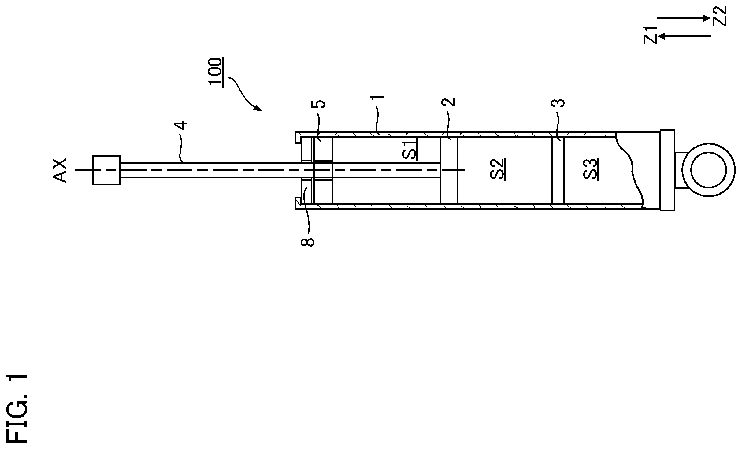
is a cross-sectional diagram of a shock absorber including a sealing device according to a first embodiment.
is a diagram illustrating the sealing device shown in .
is a diagram illustrating the sealing device shown in .
is an explanatory diagram of a state of an outer seal included in a sealing device of a reference example.
is a diagram illustrating a portion of a sealing device according to a second embodiment.
is a diagram illustrating a portion of a sealing device according to a third embodiment.
is a diagram illustrating a portion of a sealing device according to a fourth embodiment.
is a diagram illustrating a portion of a sealing device according to a fifth embodiment.
is a diagram illustrating a portion of a sealing device according to a sixth embodiment.
is a diagram illustrating a portion of a sealing device according to a seventh embodiment.
is a diagram illustrating a portion of a sealing device according to an eighth embodiment.
is a diagram illustrating a portion of a sealing device according to a ninth embodiment.
DETAILED DESCRIPTION
Preferred embodiments according to the present invention are explained below with reference to the accompanying drawings. It is of note that dimensions and scales of parts shown in the drawings may differ from those of actual products, and some parts are schematically illustrated for ease of understanding. Further, the scope of the present invention is not limited to the embodiments unless otherwise stated in the following descriptions.
1. First Embodiment
1A. Shock Absorber 100
is a cross-sectional diagram of a shock absorber 100 including a sealing device 8 according to a first embodiment. In the following descriptions, an upward direction from any point in the diagrams is referred to as the “Z1 direction,” and a downward direction from any point downward in the diagrams is referred to as the “Z2 direction” (or “downward.”) Both the Z1 direction and the Z2 direction extend along an axial line AX, as will be described later.
The shock absorber 100 illustrated in is a telescopic damper that damps shock such as vibration. The shock absorber 100 is used in, for example, automobiles or other vehicles. The shock absorber 100 generates a damping force to reduce vibration of a vehicle.
The shock absorber 100 illustrated in is a single-cylinder shock absorber, and includes a cylinder 1 , a piston 2 , a free piston 3 , a rod 4 , a rod guide 5 , and the sealing device 8 .
The cylinder 1 is made of metal and has, for example, a bottomed cylindrical shape. The cylinder 1 has a space extending along the axial line AX. The piston 2 is slidably disposed in the cylinder 1 and has, for example, a disk shape. The piston 2 is connected to the rod 4 . The free piston 3 is slidably disposed in the cylinder 1 and has, for example, a disk shape.
A space in the cylinder 1 is partitioned (divided) by the piston 2 and the free piston 3 into two oil chambers S 1 and S 2 and a gas chamber S 3 . The oil chamber S 1 and the oil chamber S 2 are partitioned (divided) by the piston 2 . The oil chamber S 2 and the gas chamber S 3 are partitioned (divided) by the free piston 3 .
The oil chamber S 1 and the oil chamber S 2 are each filled with hydraulic oil. Although not illustrated in the drawings, the piston 2 includes a communication passage through which the oil chamber S 1 and the oil chamber S 2 communicate with each other. A damping valve is a damping-force generating element, and is disposed in the communication passage. The damping valve opens or closes the communication passage depending on a differential pressure between the oil chamber S 1 and the oil chamber S 2 . A damping force is generated by resistance of the hydraulic oil passing between the oil chamber S 1 and the oil chamber S 2 through the communication passage. The gas chamber S 3 is filled with a high-pressure gas. The free piston 3 moves in response to a change in pressure of the hydraulic oil in the oil chamber S 2 acting on the free piston 3 as the piston 2 moves.
The rod 4 is made of metal and extends along the axial line AX. The rod 4 includes an end in the Z1 direction and an end in the Z2 direction. The end in the Z1 direction is exposed from the cylinder 1 , and the end in the Z2 direction is disposed in the cylinder 1 . The end in the Z2 direction is connected to the piston 2 . As the piston 2 moves, the rod 4 moves along the axial line AX. The piston 2 moves back and forth inside the cylinder 1 , whereby a length changes of a portion of the rod 4 exposed from the cylinder 1 .
The rod guide 5 is disposed close to the end of the internal space of the cylinder 1 in the Z1 direction. The rod guide 5 slidably supports the rod 4 . Although not illustrated in detail in , the rod guide 5 includes a bush and a rod guide. The bush is a bearing made of metal and is annular in shape. The rod guide is made of metal, is annular in shape, and holds the bush.
The sealing device 8 is disposed between the rod guide 5 and the end in the Z1 direction of the internal space of the cylinder 1 . The sealing device 8 seals a space between an inner circumferential surface of the cylinder 1 and an outer circumferential surface of the rod 4 . The sealing device 8 is described later in detail.
In the shock absorber 100 such as described above, of the cylinder 1 and the rod 4 , one may be fixed to a vehicle body of the vehicle and the other may be fixed to a suspension of the vehicle.
1B. Sealing Device 8
are diagrams illustrating the sealing device 8 shown in . As illustrated in , the sealing device 8 includes a metal ring 84 , a dust lip 85 , an outer circumferential lip 86 , a seal housing 81 , an inner seal 82 , and an outer seal 83 . The seal housing 81 and the inner seal 82 constitute a structure 80 . The inner seal 82 and the outer seal 83 constitute a seal member that seals a space between the seal housing 81 and the rod 4 .
illustrates the sealing device 8 , which is assembled between the cylinder 1 and the rod 4 . illustrates shapes of the dust lip 85 , the inner seal 82 , and the outer seal 83 in their natural state. to 12 referred to later also illustrate these members in their natural state in substantially the same manner as shown in .
The metal ring 84 is annular in shape and is disposed between the rod 4 and the cylinder 1 .
The dust lip 85 is made of rubber or another elastic material, and is bonded by cross-linking to a section of the metal ring 84 closer to its inner circumference than its outer circumference. A portion of the dust lip 85 is bonded by cross-linking to the inner circumferential surface of the metal ring 84 . As illustrated in , a lip end 851 of the dust lip 85 includes a tightening allowance relative to the outer circumferential surface of the rod 4 . As illustrated in , the rod 4 is inserted inside the dust lip 85 so that the lip end 851 is in slidable contact with the rod 4 . The dust lip 85 prevents ingress of foreign matter such as dust and dirt into the cylinder 1 .
The outer circumferential lip 86 is made of rubber or another elastic material, and is bonded by cross-linking to a section of the metal ring 84 closer to its outer circumference than its inner circumference. A lip end 861 of the outer circumferential lip 86 is inserted into the cylinder 1 to be in slidable contact with the cylinder 1 .
The seal housing 81 is made of metal, is annular in shape, and is disposed between the rod 4 and the cylinder 1 . The seal housing 81 holds the inner seal 82 and the outer seal 83 . The seal housing 81 includes a stepped inner circumferential surface 810 . Specifically, the inner circumferential surface 810 includes a first cylindrical surface 8101 , a second cylindrical surface 8102 , a third cylindrical surface 8103 , a first bottom surface 8104 , and a second bottom surface 8105 .
Each of the first cylindrical surface 8101 , the second cylindrical surface 8102 , and the third cylindrical surface 8103 extends along the axial line AX over the entire circumference. Each of the first bottom surface 8104 and the second bottom surface 8105 extends radially over the entire circumference. The respective inner diameters of the first cylindrical surface 8101 , the second cylindrical surface 8102 , and the third cylindrical surface 8103 are different, with the inner diameter of the first cylindrical surface 8101 being the smallest, the inner diameter of the second cylindrical surface 8102 being the second smallest, and the inner diameter of the third cylindrical surface 8103 being the largest. The first bottom surface 8104 connects the first cylindrical surface 8101 and the second cylindrical surface 8102 . The second bottom surface 8105 connects the second cylindrical surface 8102 and the third cylindrical surface 8103 .
A first space C 1 and a second space C 2 are formed between the seal housing 81 and the rod 4 . The first space C 1 is formed at a position in the Z1 direction relative to the second space C 2 . The first space C 1 has an outer diameter smaller than that of the second space C 2 . In other words, the distance between the seal housing 81 and the rod 4 in the first space C 1 is shorter than the distance between the seal housing 81 and the rod 4 in the second space C 2 . Further, a portion of the inner seal 82 is disposed in the first space C 1 . In the second space C 2 , the remaining portions of the inner seal 82 and the outer seal 83 are disposed. The hydraulic oil flows into a clearance C 0 between the outer seal 83 and the rod guide 5 .
The seal housing 81 has a contact face that is in contact with the outer seal 83 . The contact face has a concave portion 811 . Specifically, the concave portion 811 is formed on the inner circumferential surface 810 of the seal housing 81 . More specifically, the concave portion 811 is a recess formed on the third cylindrical surface 8103 of the inner circumferential surface 810 . The concave portion 811 extends circumferentially as a groove, and has a triangular shape as viewed in cross section. The width of the concave portion 811 as viewed in cross section along the axial line AX increases in the direction from the cylinder 1 toward the rod 4 .
The inner seal 82 includes a portion that extends radially from the rod 4 , and a portion that extends along the axial line AX. As illustrated in , the inner seal 82 includes a tightening allowance relative to the outer circumferential surface of the rod 4 . In the first space C 1 , the inner seal 82 is held in a pressed state between the seal housing 81 and the rod 4 . The inner seal 82 is held in a pressed state between the outer seal 83 and the rod 4 in the second space C 2 . Movement of the inner seal 82 in the Z1 direction is limited by the seal housing 81 . The inner seal 82 is pressed in the Z1 direction by a hydraulic pressure of the hydraulic oil that flows into the clearance C 0 . The inner seal 82 is made of an elastic material such as fluorine rubber or nitrile butadiene rubber (NBR).
The outer seal 83 is disposed between the inner seal 82 and the seal housing 81 , and is in contact with the inner seal 82 and the seal housing 81 . The outer seal 83 is press-fitted between the inner seal 82 and the seal housing 81 . Accordingly, as illustrated in , the inner circumferential edge of the outer seal 83 is slightly displaced in the Z2 direction, when the outer seal 83 is in an assembled state. The outer seal 83 is made of an elastic material such as nitrile butadiene rubber (NBR).
is an explanatory diagram showing a state of the outer seal 83 included in a sealing device 8 x , which is a reference example. The sealing device 8 x in the reference example includes a seal housing 81 x . The seal housing 81 x does not have the concave portion 811 illustrated in or 3 .
When the rod 4 is incorporated into the sealing device 8 X, the rod 4 pushes the inner seal 82 in a direction such that the inner seal 82 separates radially from the axial line AX, and the inner seal 82 moves toward the clearance C 0 . As a result, the outer seal 83 is pushed by the inner seal 82 , so that the outer seal 83 partially separates from the inner seal 82 as illustrated in . In this case, contact between the inner seal 82 and the rod 4 becomes unstable, and a pressing force of the inner seal 82 against the rod 4 is reduced. Accordingly, the original sealing capability of the inner seal 82 cannot be maintained, and leakage of the hydraulic oil may occur.
In the sealing device 8 according to the present embodiment, to solve the above problem, the seal housing 81 is provided with the concave portion 811 as illustrated in . The seal housing 81 has a contact face that is in contact with the outer seal 83 , and the contact face has the concave portion 811 , so that when the sealing device 8 is incorporated into the rod 4 , the outer seal 83 pushed by the inner seal 82 is partially deformed to penetratingly enter the concave portion 811 of the seal housing 81 as illustrated in . The concave portion 811 functions as a clearance portion into which the outer seal 83 pushed by the inner seal 82 moves. Therefore, the outer seal 83 can be prevented from partially or entirely separating from the inner seal 82 , and degradation in sealing properties due to the inner seal 82 can be prevented. By this configuration, the original sealing properties of the sealing device 8 can be maintained.
2. Second Embodiment
A second embodiment will now be described. In the modes exemplified below, elements having functions substantially the same as those of the first embodiment are denoted by reference signs used in the description of the first embodiment, and detailed explanation thereof is omitted as appropriate.
is a diagram illustrating a portion of a sealing device 8 A according to the second embodiment. Differences between the sealing device 8 A according to the second embodiment and the sealing device 8 according to the first embodiment are described below, and explanation of matters that are substantially the same is omitted as appropriate.
The sealing device 8 A illustrated in includes an outer seal 83 A with a contact face that is in contact with a seal housing 81 A. The contact face has a concave portion 831 . Specifically, the concave portion 831 is a recess formed on an outer circumferential surface of the outer seal 83 A. The concave portion 831 extends circumferentially. The concave portion 831 is a groove that has a triangular shape as viewed in cross section. The width of the concave portion 831 as viewed in cross section along the axial line AX increases in the direction from the rod 4 toward the cylinder 1 . A structure 80 A includes the seal housing 81 A. Unlike the first embodiment, the seal housing 81 A does not have the concave portion 811 .
The outer seal 83 A has a contact face that is in contact with the seal housing 81 A, and the contact face has the concave portion 831 . Consequently, although not illustrated in the drawings, when the sealing device 8 A is incorporated into the rod 4 , the outer seal 83 A pushed by the inner seal 82 is pressed against an inner circumferential surface of the seal housing 81 A, and thus deformed. This deformation causes the concave portion 831 to be deformed and pressed against the inner circumferential surface of the seal housing 81 A. Therefore, the outer seal 83 A can be prevented from partially or entirely separating from the inner seal 82 . This prevents degradation in sealing properties due to the inner seal 82 . By this configuration, the original sealing properties of the sealing device 8 A can be maintained.
3. Third Embodiment
A third embodiment will now be described. In the modes exemplified below, elements having functions substantially the same as those of the first embodiment are denoted by reference signs used in the description of the first embodiment, and detailed explanation thereof is omitted as appropriate.
is a diagram illustrating a portion of a sealing device 8 B according to the third embodiment. Differences between the sealing device 8 B according to the third embodiment and the sealing device 8 according to the first embodiment are described below and explanation of substantially the same matters is omitted as appropriate.
The sealing device 8 B illustrated in has a structure 80 B that includes a seal housing 81 B. The seal housing 81 B has a second portion 812 that is a concave portion. The second portion 812 has substantially the same configuration as the concave portion 811 according to the first embodiment. The seal housing 81 B has a contact face that is in contact with an outer circumferential surface of an outer seal 83 B. The second portion 812 is formed on the contact face. Specifically, the second portion 812 is formed on the third cylindrical surface 8103 . The second portion 812 extends circumferentially. The second portion 812 is a groove that is triangular in shape as viewed in cross section.
The outer seal 83 B has a first portion 832 that is a convex portion. The first portion 832 fits in the second portion 812 . The outer seal 83 B has a contact face that is in contact with the third cylindrical surface 8103 . The first portion 832 is formed on the contact face. The first portion 832 extends circumferentially. The first portion 832 is a convex portion that is triangular in shape as viewed in cross section.
As described above, the seal housing 81 B has the second portion 812 , and the outer seal 83 B has the first portion 832 that fits in the second portion 812 . By this configuration, when the sealing device 8 B is incorporated into the rod 4 , the outer seal 83 B is less likely to come away from the structure 80 B. Accordingly, the outer seal 83 B can be prevented from partially or entirely separating from the inner seal 82 . This prevents degradation in sealing properties due to the inner seal 82 . By this configuration, the original sealing properties of the sealing device 8 B can be maintained.
4. Fourth Embodiment
A fourth embodiment will now be described. In the modes exemplified below, elements having functions substantially the same as those of the first embodiment are denoted by reference signs used in the description of the first embodiment, and detailed explanation thereof is omitted as appropriate.
is a diagram illustrating a portion of a sealing device 8 C according to the fourth embodiment. Differences between the sealing device 8 C according to the fourth embodiment and the sealing device 8 according to the first embodiment are described below, and explanation of substantially the same matters is omitted as appropriate.
The sealing device 8 C illustrated in has a structure 80 C that includes a seal housing 81 C. The seal housing 81 C has a second portion 813 that is a convex portion. The seal housing 81 C has a contact face that is in contact with an outer circumferential surface of an outer seal 83 C. The second portion 813 is formed on the contact face. Specifically, the second portion 813 is formed on the third cylindrical surface 8103 . The second portion 813 extends circumferentially. The second portion 813 is a convex portion that is triangular in shape as viewed in cross section.
The outer seal 83 C has a first portion 833 that is a concave portion. The first portion 833 fits in the second portion 813 . The outer seal 83 C has a contact face that is in contact with the third cylindrical surface 8103 . The first portion 833 is formed on the contact face. The first portion 833 extends circumferentially. The first portion 833 is a groove that is triangular in shape as viewed in cross section.
As described above, the seal housing 81 C has the second portion 813 , and the outer seal 83 C has the first portion 833 that fits in the second portion 813 . By this configuration, when the sealing device 8 C is incorporated into the rod 4 , the outer seal 83 C is less likely to come away from the structure 80 C. Accordingly, the outer seal 83 C can be prevented from partially or entirely separating from the inner seal 82 . This prevents degradation in sealing properties due to the inner seal 82 . By this configuration, the original sealing properties of the sealing device 8 C can be maintained.
5. Fifth Embodiment
A fifth embodiment will now be described. In the modes exemplified below, elements having functions substantially the same as those of the first embodiment are denoted by reference signs used in the description of the first embodiment, and detailed explanation thereof is omitted as appropriate.
is a diagram illustrating a portion of a sealing device 8 D according to the fifth embodiment. Differences between the sealing device 8 D according to the fifth embodiment and the sealing device 8 according to the first embodiment are described below, and explanation of substantially the same matters is omitted as appropriate.
The sealing device 8 D illustrated in has a structure 80 D that includes a seal housing 81 D. The seal housing 81 D has a second portion 814 that includes a plurality of concave portions and a plurality of convex portions. The seal housing 81 D has a contact face that is in contact with an outer circumferential surface of an outer seal 83 D. The second portion 814 is formed on the contact face. Specifically, the second portion 814 is formed on the third cylindrical surface 8103 . The second portion 814 extends circumferentially.
An inner seal 82 D has a second portion 821 that includes a plurality of concave portions and a plurality of convex portions. The inner seal 82 D has a contact face that is in contact with an inner circumferential surface of the outer seal 83 D. The second portion 821 is formed on the contact face. Specifically, the second portion 821 is formed on an outer circumferential surface of the inner seal 82 D. The second portion 821 extends circumferentially.
The outer seal 83 D has first portions 834 and 835 . Each of the first portions 834 and 835 includes a plurality of concave portions and a plurality of convex portions. The first portion 834 fits in the second portion 814 , and the first portion 835 fits in the second portion 821 . The outer seal 83 D has a contact face that is in contact with the third cylindrical surface 8103 . The first portion 834 is formed on the contact face. Specifically, the first portion 834 is formed on the outer circumferential surface of the outer seal 83 D. The outer seal 83 D has a contact face that is in contact with the inner seal 82 D. The first portion 835 is formed on the contact face. Specifically, the first portion 835 is formed on the inner circumferential surface of the outer seal 83 D. Each of the first portions 834 and 835 extends circumferentially.
As described above, the seal housing 81 D has the second portion 814 , and the inner seal 82 D has the second portion 821 . The outer seal 83 D has the first portion 834 that fits in the second portion 814 , and the first portion 835 that fits in the second portion 821 . By this configuration, when the sealing device 8 D is incorporated into the rod 4 , the outer seal 83 D is less likely to come away from the structure 80 D. Accordingly, the outer seal 83 D can be prevented from partially or entirely separating from the inner seal 82 D. This prevents degradation in sealing properties due to the inner seal 82 D. By this configuration, the original sealing properties of the sealing device 8 D can be maintained.
The outer seal 83 D has the first portions 834 and 835 . By this configuration, the outer seal 83 D can further be prevented from partially or entirely separating from the inner seal 82 D, compared to the configuration in which the outer seal 83 D has one only of the first portions 834 and 835 .
6. Sixth Embodiment
A sixth embodiment will now be described. In the modes exemplified below, elements having functions substantially the same as those of the first embodiment are denoted by reference signs used in the description of the first embodiment, and detailed explanation thereof is omitted as appropriate.
is a diagram illustrating a portion of a sealing device 8 E according to the sixth embodiment. Differences between the sealing device 8 E according to the sixth embodiment and the sealing device 8 according to the first embodiment are described below, and explanation of substantially the same matters is omitted as appropriate.
The sealing device 8 E illustrated in has a structure 80 E that includes an inner seal 82 E. The inner seal 82 E has a second portion 822 that is a convex portion. The inner seal 82 E has a contact face that is in contact with an inner circumferential surface of an outer seal 83 E. The second portion 822 is formed on the contact face. Specifically, the second portion 822 is formed on an outer circumferential surface of the inner seal 82 E. The second portion 822 extends circumferentially. The second portion 822 is a convex portion that is rectangular in shape as viewed in cross section. Unlike the first embodiment, a seal housing 81 E does not have the concave portion 811 .
The outer seal 83 E has a first portion 836 that is a concave portion. The first portion 836 fits in the second portion 822 . The outer seal 83 E has a contact face that is in contact with the inner seal 82 E. The first portion 836 is formed on the contact face. Specifically, the first portion 836 is formed on the inner circumferential surface of the outer seal 83 E. The first portion 836 extends circumferentially. The first portion 836 is a groove that is rectangular in shape as viewed in cross section.
As described above, the inner seal 82 E has the second portion 822 , and the outer seal 83 E has the first portion 836 that fits in the second portion 822 . By this configuration, when the sealing device 8 E is incorporated into the rod 4 , the outer seal 83 E is less likely to come away from the inner seal 82 E. Accordingly, the outer seal 83 E can be prevented from partially or entirely separating from the inner seal 82 E. This prevents degradation in sealing properties due to the inner seal 82 E. By this configuration, the original sealing properties of the sealing device 8 E can be maintained.
Particularly, the inner seal 82 E fits in the outer seal 83 E by way of the first portion 836 and the second portion 822 , so that the inner seal 82 E and the outer seal 83 E can be integrated as a single piece. Accordingly, the outer seal 83 E can be effectively prevented from partially or entirely separating from the inner seal 82 E.
7. Seventh Embodiment
A seventh embodiment will now be described. In the modes exemplified below, elements having functions substantially the same as those of the first embodiment are denoted by reference signs used in the description of the first embodiment, and detailed explanation thereof is omitted as appropriate.
is a diagram illustrating a portion of a sealing device 8 F according to the seventh embodiment. Differences between the sealing device 8 F according to the seventh embodiment and the sealing device 8 according to the first embodiment are described below, and explanation of substantially the same matters is omitted as appropriate.
The sealing device 8 F illustrated in has a structure 80 F that includes an inner seal 82 F. The inner seal 82 F has a second portion 823 that is a concave portion. The inner seal 82 F has a contact face that is in contact with an inner circumferential surface of an outer seal 83 F. The second portion 823 is formed on the contact face. Specifically, the second portion 823 is formed on an outer circumferential surface of the inner seal 82 F. The second portion 823 extends circumferentially. The second portion 823 is a groove that is rectangular in shape as viewed in cross section. Unlike the first embodiment, a seal housing 81 F does not have the concave portion 811 .
The outer seal 83 F has a first portion 837 that is a convex portion. The first portion 837 fits in the second portion 823 . The outer seal 83 F has a contact face that is in contact with the outer circumferential surface of the inner seal 82 F. The first portion 837 is formed on the contact face. Specifically, the first portion 837 is formed on the inner circumferential surface of the outer seal 83 F. The first portion 837 extends circumferentially. The first portion 837 is a projection that is rectangular in shape as viewed in cross section.
As described above, the inner seal 82 F has the second portion 823 , and the outer seal 83 F has the first portion 837 that fits in the second portion 823 . By this configuration, when the sealing device 8 F is incorporated into the rod 4 , the outer seal 83 F is less likely to come away from the inner seal 82 F. Accordingly, the outer seal 83 F can be prevented from partially or entirely separating from the inner seal 82 F. This prevents degradation in sealing properties due to the inner seal 82 F. By this configuration, the original sealing properties of the sealing device 8 F can be maintained.
Particularly, the inner seal 82 F fits in the outer seal 83 F by way of the first portion 837 and the second portion 823 , so that the inner seal 82 F and the outer seal 83 F can be integrated as a single piece. Accordingly, the outer seal 83 F can be effectively prevented from partially or entirely separating from the inner seal 82 F.
8. Eighth Embodiment
An eighth embodiment will now be described. In the modes exemplified below, elements having functions substantially the same as those of the first embodiment are denoted by reference signs used in the description of the first embodiment, and detailed explanation thereof is omitted as appropriate.
is a diagram illustrating a portion of a sealing device 8 G according to the eighth embodiment. Differences between the sealing device 8 G according to the eighth embodiment and the sealing device 8 according to the first embodiment are described below, and explanation of substantially the same matters is omitted as appropriate.
The sealing device 8 G illustrated in has a structure 80 G that includes an inner seal 82 G. The inner seal 82 G has a second portion 824 . The second portion 824 is a convex portion. The inner seal 82 G has a contact face that is in contact with an inner circumferential surface of an outer seal 83 G. The second portion 824 is formed on the contact face. Specifically, the second portion 824 is formed on an outer circumferential surface of the inner seal 82 G. The second portion 824 extends circumferentially. A seal housing 81 G does not have the concave portion 811 according to the first embodiment.
The outer seal 83 G has a first portion 838 . The first portion 838 is a concave portion. The first portion 838 fits in the second portion 824 . The outer seal 83 G has a contact face that is in contact with the outer circumferential surface of the inner seal 82 G. The first portion 838 is formed on the contact face. Specifically, the first portion 838 is formed on the inner circumferential surface of the outer seal 83 G. The first portion 838 extends circumferentially.
The second portion 824 may be regarded as a step constituted of a concave portion and a convex portion. The first portion 838 may be regarded as a step constituted of a concave portion and a convex portion. The second portion 824 may be regarded as a concave portion, while the first portion 838 may be regarded as a convex portion.
As described above, the inner seal 82 G has the second portion 824 , and the outer seal 83 G has the first portion 838 that fits in the second portion 824 . By this configuration, when the sealing device 8 G is incorporated into the rod 4 , the outer seal 83 G is less likely to come away from the inner seal 82 G. Accordingly, the outer seal 83 G can be prevented from partially or entirely separating from the inner seal 82 G. This prevents degradation in sealing properties due to the inner seal 82 G. By this configuration, the original sealing properties of the sealing device 8 G can be maintained.
Particularly, the inner seal 82 G fits in the outer seal 83 G by way of the first portion 838 and the second portion 824 , so that the inner seal 82 G and the outer seal 83 G can be integrated as a single piece. Accordingly, the outer seal 83 G can be effectively prevented from partially or entirely separating from the inner seal 82 G.
9. Ninth Embodiment
A ninth embodiment will now be explained. In the modes exemplified below, elements having functions substantially the same as those of the first embodiment are denoted by reference signs used in the explanation of the first embodiment, and detailed explanation thereof is omitted as appropriate.
is a diagram illustrating a portion of a sealing device 8 H according to the ninth embodiment. Differences between the sealing device 8 H according to the ninth embodiment and the sealing device 8 according to the first embodiment are described below, and explanation of substantially the same matters is omitted as appropriate.
The sealing device 8 H illustrated in has a structure 80 H that includes a second portion 801 . The second portion 801 is a concave portion included in the structure 80 H. The second portion 801 is provided between a seal housing 81 H and an inner seal 82 H. The structure 80 H has a contact face that is in contact with an outer seal 83 H. The second portion 801 is formed on the contact face. The second portion 801 extends circumferentially.
The outer seal 83 H has a first portion 839 . The first portion 839 is a convex portion. The first portion 839 fits in the second portion 801 . The outer seal 83 H has a contact face that is in contact with the structure 80 H. The first portion 839 is formed on the contact face. The first portion 839 extends circumferentially.
As described above, the structure 80 H has the second portion 801 , and the outer seal 83 H has the first portion 839 that fits in the second portion 801 . By this configuration, when the sealing device 8 H is incorporated into the rod 4 , the outer seal 83 H is less likely to come away from the structure 80 H. Accordingly, the outer seal 83 H can be prevented from partially or entirely separating from the structure 80 H. Consequently, the outer seal 83 H can be prevented from partially or entirely separating from the inner seal 82 H. This prevents degradation in sealing properties due to the inner seal 82 H. By this configuration, the original sealing properties of the sealing device 8 H can be maintained.
Particularly, the second portion 801 is provided between the seal housing 81 H and the inner seal 82 H, and the first portion 839 fits in the second portion 801 . By this configuration, the first portion 839 is interposed between the seal housing 81 H and the inner seal 82 H. Accordingly, the outer seal 83 H can be effectively prevented from partially or entirely separating from the structure 80 H.
The present invention is described above based on the preferred embodiments. However, the present invention is not limited to the preferred embodiments. The configurations of elements of the present invention can be replaced with configurations that provide substantially the same functions as those of the preferred embodiments, and appropriate changes can be made thereto. Further, any of the configurations of the preferred embodiments may be combined with each other.
The sealing device of the present invention may be applied to an extension mechanism other than a shock absorber. For example, the invention may be applied to a gas stay.
Figures (8)
Citations
This patent cites (22)
- US3848880
- US4949819
- US5346230
- US6454273
- US8360534
- US8827381
- US9933071
- US2006/0185952
- US2015/0316119
- US2017/0138432
- US2019/0277365
- US2020/0325989
- US2021/0140507
- US1729045
- US2797672
- US2353336
- US2000-346202
- US2006226424
- US2010-223282
- US2015218817
- US2018-0181210
- US2019-176784