Abstract
In a magnet holder 4 including: a shaft attachment portion 41 to which a shaft 2 is press-fitted and fixed; and a magnet holding portion 42 that is provided on one side in an axial direction of the shaft attachment portion 41 and holds a periphery of a magnet 5 , and provided with an undercut portion 50 that engages with the magnet 5 in the axial direction on an inner peripheral surface 43 of the magnet holding portion 42 facing the magnet 5 , the magnet holding portion 42 and the shaft attachment portion 41 are integrally formed of sintered metal, an outer peripheral surface and an end surface of the magnet holding portion 42 and an inner peripheral surface of the shaft attachment portion 41 are sized, and the undercut portion 50 is formed by plastic deformation of the magnet holding portion 42.
Claims (5)
1. A magnet holder comprising: a cylindrical body defining opposing inner and outer peripheral surfaces and having opposing axial ends; a shaft attachment portion disposed within one axial end of the cylindrical body to which a shaft is press-fitted and fixed; and a magnet holding portion disposed within the other axial end of the cylindrical body opposite the shaft attachment portion and that holds a periphery of a magnet, the magnet holding portion comprising a space defined by an inner peripheral surface of the magnet holding portion and a radially-extending end surface of the shaft attachment portion on a magnet side thereof, the magnet holding portion being provided with a circumferentially-extending undercut portion that engages with the magnet in an axial direction on the inner peripheral surface of the magnet holding portion facing the magnet to prevent relative axial movement therebetween, wherein: the magnet holding portion and the shaft attachment portion are integrally formed of sintered metal; an outer peripheral surface and an end surface of the magnet holding portion and an inner peripheral surface of the shaft attachment portion are sized; the undercut portion is formed by plastic deformation of the magnet holding portion by a pressing force in an inner diameter direction generated by pressurizing an outer circumferential surface of the magnet holding portion during the sizing; the inner peripheral surface of the magnet holding portion has a circumferentially-extending tapered surface and a circumferentially-extending reverse tapered surface that continues from the circumferentially-extending tapered surface on a shaft attachment portion side; the circumferentially-extending tapered surface is inclined toward an inner diameter side of the magnet holding portion as the circumferentially-extending tapered surface approaches the shaft attachment portion; the circumferentially-extending reverse tapered surface is inclined toward an outer diameter side of the magnet holding portion as the circumferentially-extending reverse tapered surface approaches the shaft attachment portion; the undercut portion is formed by the circumferentially-extending reverse tapered surface; and a recess that engages with the magnet in a circumferential direction is provided on the radially-extending end surface on the magnet side of the shaft attachment portion to prevent relative rotation therebetween.
Show 4 dependent claims
2. The magnet holder according to claim 1 , wherein a groove portion is provided on the inner peripheral surface of the shaft attachment portion, the groove portion extending in the axial direction and opening to an end surface of the shaft attachment portion on a side opposite to the magnet side the magnet is provided.
3. The magnet holder according to claim 1 , wherein the magnet holder is formed of an austenitic stainless steel material.
4. A magnet unit comprising: the magnet holder according to claim 1 ; and a magnet held by the magnet holding portion of the magnet holder.
5. The magnet holder according to claim 3 , wherein a groove portion is provided on the inner peripheral surface of the shaft attachment portion, the groove portion extending in the axial direction and opening to an end surface of the shaft attachment portion on a side opposite to the magnet side.
Full Description
Show full text →
TECHNICAL FIELD
The present invention relates to a magnet holder and a magnet unit including the magnet holder.
BACKGROUND ART
Some rotation angle detection devices for detecting a rotation angle of a rotating body detect the rotation angle by detecting a change in a magnetic field formed by a magnet that rotates integrally with the rotating body using a magnetic sensor, and for example, this type of rotation angle detection device is provided for detecting a rotation angle of an electric motor mounted on a power steering device of an automobile.
The rotation angle detection device is provided with the magnet and the magnet holder for holding the magnet. For example, Patent Literature 1 describes a rotation angle detection device having a configuration in which a holder member attached to one end side in an axial direction of the rotating body holds the magnet on a side opposite to a side attached to a rotating shaft in the axial direction. In this device, when the holder member and the magnet rotate integrally with a rotation shaft due to rotation of the rotation shaft, the magnetic sensor provided to face the magnet can detect the change in the magnetic field and detect the rotation angle of the rotation shaft.
In the device as described above, a retaining mechanism is generally provided in order to prevent the magnet from falling off the holder member. For example, in Patent Literature 2, as illustrated in , a cylindrical holder member 101 is provided, and the magnet member 102 is integrally molded with a recess 101 a that is provided on an inner peripheral surface side of the holder member 101 and opens to one end side in the axial direction. An inner peripheral wall of the holder member 101 forming the recess 101 a is an undercut portion 101 b having a diameter increasing from one side to the other side in the axial direction. The magnet member 102 is locked by the undercut portion 101 b , and the magnet member 102 can be prevented from falling off the opening on the one side in the axial direction of the holder member 101 .
CITATIONS LIST
Patent Literature
• Patent Literature 1: Japanese Patent No. 5141780 • Patent Literature 2: Japanese Patent Application Laid-Open No. 2016-205977
SUMMARY OF INVENTION
Technical Problems
It is difficult to integrally mold an undercut shape as in Patent Literature 2 when the holder member is molded by die molding. Therefore, for example, Patent Literature 2 discloses that the undercut portion 101 b is formed by machining such as lathe machining. However, such a post-processing method has a problem that the number of steps increases, leading to an increase in manufacturing cost.
In view of such circumstances, an object of the present invention is to manufacture a magnet holder having a magnet retaining mechanism at low cost.
Solutions to Problems
In order to solve the above problems, the present invention is a magnet holder including: a shaft attachment portion to which a shaft is press-fitted and fixed; and a magnet holding portion that is provided on one side in an axial direction of the shaft attachment portion and holds a periphery of a magnet, and provided with an undercut portion that engages with the magnet in the axial direction on an inner surface of the magnet holding portion facing the magnet, in which the magnet holding portion and the shaft attachment portion are integrally formed of sintered metal, an outer peripheral surface and an end surface of the magnet holding portion and an inner peripheral surface of the shaft attachment portion are sized, and the undercut portion is formed by plastic deformation of the magnet holding portion.
The sintered metal is rich in plastic fluidity, so that high surface accuracy can be obtained by sizing. Therefore, as in the above-described configuration of the present invention, by integrally forming the magnet holding portion and the shaft attachment portion with sintered metal and sizing the inner peripheral surface of the shaft attachment portion, the inner peripheral surface with high accuracy can be molded by one shot without requiring a plurality of steps. In addition, by forming the undercut portion by plastic deformation, processing cost can be reduced as compared with the case of machining. As described above, the cost of the magnet holder can be reduced. Furthermore, by increasing the accuracy of the inner peripheral surface of the shaft attachment portion, it is easy to control a press-fitting margin when the shaft is press-fitted into the shaft attachment portion, and it is possible to improve attachment accuracy (coaxiality or the like) of the shaft to the magnet holder.
As the magnet holder described above, the magnet holding portion can be plastically deformed by a pressing force in an inner diameter direction acting on the magnet holding portion with sizing. By plastically deforming the magnet holding portion with the pressing force accompanying the sizing, it is possible to simultaneously perform the sizing of the inner peripheral surface of the shaft attachment portion and formation of the undercut portion. Therefore, productivity of the magnet holder can be improved.
As the magnet holder described above, a recess that engages with the magnet in a circumferential direction can be provided on an end surface on a magnet side of the shaft attachment portion. This makes it possible to prevent relative rotation of the magnet with respect to the magnet holder.
As the magnet holder described above, a groove portion can be provided on an inner peripheral surface of the shaft attachment portion, the groove portion extending in the axial direction and opening to an end surface of the shaft attachment portion on a side opposite to a side where the magnet is provided. Accordingly, the air inside the magnet holder can be released to the outside through the groove portion at the time of axial press-fitting, and it is possible to prevent breakage of the magnet holder and falling off the magnet from the magnet holder.
As the magnet holder described above, the undercut portion can be formed by a tapered surface.
As the magnet holder described above, the undercut portion can be formed by a projecting portion.
The magnet holder described above can be formed of an austenitic stainless steel material. This makes it possible to provide a magnet holder that does not affect the magnetic field of the magnet.
A magnet unit can include the magnet holder described above and a magnet held by a magnet holding portion of the magnet holder.
Advantageous Effects of Invention
In the present invention, the manufacturing cost of the magnet holder can be reduced.
BRIEF DESCRIPTION OF DRAWINGS
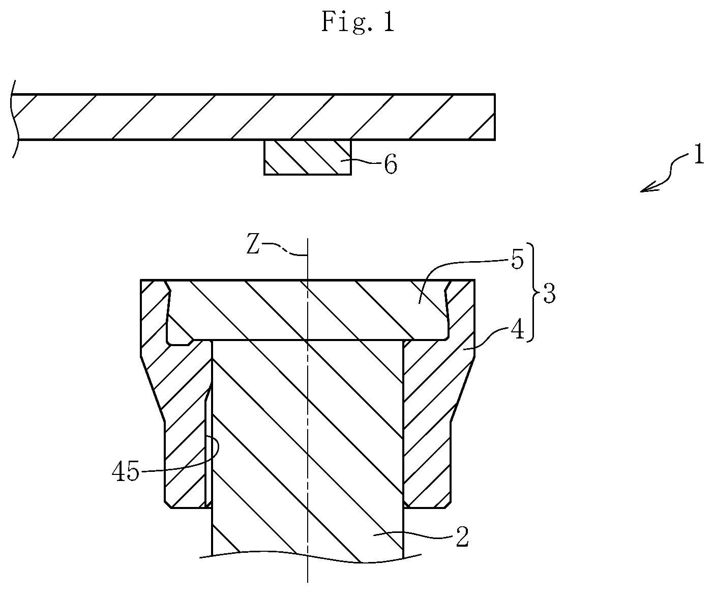
is a cross-sectional view of a rotation angle detection device including a magnet unit according to an embodiment of the present invention.
A is a plan view illustrating a magnet holder according to the embodiment.
B is a cross-sectional view taken along a line A-A of A .
is a cross-sectional view illustrating a recess having a configuration different from that of the embodiment.
is a cross-sectional view illustrating a sintered body which is an intermediate molded product of the magnet holder of .
A is a cross-sectional view illustrating a sizing step.
B is a cross-sectional view illustrating the sizing step.
C is a cross-sectional view illustrating the sizing step.
A is a plan view illustrating the magnet holder according to another embodiment.
B is a cross-sectional view taken along a line B-B of A .
is a cross-sectional view illustrating the sintered body which is the intermediate molded product of the magnet holder of .
A is a cross-sectional view illustrating the sizing step.
B is a cross-sectional view illustrating the sizing step.
C is a cross-sectional view illustrating the sizing step.
is a cross-sectional view illustrating the magnet unit according to the other embodiment.
is a cross-sectional view illustrating a conventional rotation angle detection device.
A is a plan view illustrating the magnet holder according to still another embodiment.
B is a cross-sectional view taken along a line C-C of A .
is a cross-sectional view illustrating the sintered body which is the intermediate molded product of the magnet holder of .
A is a cross-sectional view illustrating the sizing step.
B is a cross-sectional view illustrating the sizing step.
C is a cross-sectional view illustrating the sizing step.
DESCRIPTION OF EMBODIMENTS
Hereinafter, embodiments according to the present invention will be described with reference to the drawings.
As illustrated in , a rotation angle detection device 1 includes a magnet unit 3 and a magnetic sensor 6 . The magnet unit 3 includes a magnet holder 4 and a magnet 5 , and is attached to one axial end of a rotating shaft 2 that is a shaft.
The magnet holder 4 is formed of sintered metal by powder metallurgy, and is particularly formed of a non-magnetic material so as not to affect a magnetic field of the magnet 5 . For example, it is preferable to select an austenitic stainless steel material that can be plastically deformed in a sizing step described later. The magnet 5 is a bonded magnet molded by injecting a magnetic material into the magnet holder 4 and magnetizing the magnetic material.
The magnet holder 4 has a substantially cylindrical shape (see A ), and one axial end side (upper side in ) has a larger diameter than the other axial end side. The magnet holder 4 holds the magnet 5 on the one axial end side on an inner peripheral surface side thereof.
The magnet 5 has a configuration in which N poles and S poles are alternately arranged in a circumferential direction thereof, and changes the magnetic field to be formed by rotating integrally with the rotating shaft 2 .
The magnetic sensor 6 is disposed to face the magnet 5 , and can detect a change in magnitude or direction of the magnetic field formed by the magnet 5 . A known magnetic sensor can be appropriately used for the magnetic sensor 6 .
The rotating shaft 2 is provided to be rotatable about an axis Z. When the rotating shaft 2 rotates, the magnet unit 3 attached to one end side of the rotating shaft 2 rotates integrally with the rotating shaft 2 . Thus, the magnitude or the direction of the magnetic field formed by the magnet 5 changes. Then, the magnetic sensor 6 can detect a rotation angle of the rotating shaft 2 by detecting this change. Hereinafter, an extending direction of the axis Z is also simply referred to as an axial direction.
As illustrated in B , the magnet holder 4 has a configuration in which a hollow cylindrical shaft attachment portion 41 for press-fitting and fixing the rotating shaft 2 and a hollow cylindrical magnet holding portion 42 provided on one side in the axial direction of the shaft attachment portion 41 and holding a periphery of the magnet 5 are integrated. An inner peripheral space of the shaft attachment portion 41 and an inner peripheral space of the magnet holding portion 42 are continuous in the axial direction. An inner peripheral surface (inner side surface) 43 of the magnet holding portion 42 faces the periphery of the magnet 5 , and an inner diameter dimension of the inner peripheral surface 43 is larger than an inner diameter dimension of an inner peripheral surface of the shaft attachment portion 41 . A magnet housing portion 4 a , which is a space for housing the magnet 5 , is formed by a magnet-side end surface 44 of the shaft attachment portion 41 facing an end surface of the magnet 5 and the inner peripheral surface 43 of the magnet holding portion 42 .
As illustrated in a partially enlarged view of B , a tapered portion 43 a and a reverse tapered portion 43 b are continuously provided on the inner peripheral surface 43 of the magnet holding portion 42 from the one side in the axial direction. The tapered portion 43 a is a portion having a diameter decreasing from the one side to the other side in the axial direction. Further, the reverse tapered portion 43 b is a portion having a diameter increasing from the one side to the other side in the axial direction, and an undercut portion 50 is formed by the tapered portion 43 a and the reverse tapered portion 43 b.
The end surface 44 of the shaft attachment portion 41 is provided with a recess 44 a for preventing rotation of the magnet 5 with respect to the magnet holder 4 . At least one recess 44 a may be provided, and in the present embodiment, four recesses 44 a are provided at equal intervals in the circumferential direction. However, a position where the recess for preventing the rotation of the magnet 5 is provided is not limited to the end surface 44 . For example, as illustrated in , a recess 431 may also be provided in the reverse tapered portion 43 . At least one recess 431 may be provided, and for example, four recesses 431 can be provided at equal intervals in the circumferential direction.
A groove portion 45 extending in the axial direction is provided on the inner peripheral surface of the shaft attachment portion 41 . The groove portion 45 is provided in a partial region in the circumferential direction and is open to the other axial side of the shaft attachment portion 41 . In the magnet holder 4 , the rotating shaft 2 is press-fitted into the shaft attachment portion 41 in a state where the magnet 5 is held by the magnet holding portion 42 , so that a sealed space is formed in the magnet holder 4 . On the other hand, by providing the groove portion 45 open to the other axial side, an inside and an outside of the magnet holder 4 communicate with each other via the groove portion 45 , so that the air in the magnet holder 4 can be released to the outside along with press-fitting. Thus, it is possible to prevent the magnet 5 from being detached or the magnet unit 3 from being damaged due to increase in internal pressure of the magnet holder 4 during the press-fitting of the rotating shaft 2 .
Next, a method for producing the magnet unit 3 will be described.
In the present embodiment, the magnet holder 4 is molded by powder metallurgy. That is, metal powder is compression-molded with a molding die, and then a green compact thus obtained is heated and sintered to obtain a sintered body. Then, dimensions of the sintered body are corrected by sizing to complete the magnet holder 4 .
A sintered body 4 ′ of the present embodiment obtained in the above process is illustrated in .
A portion 41 ′ corresponding to the shaft attachment portion 41 (including the recess 44 a and the groove portion 45 ) and a portion 42 ′ corresponding to the magnet holding portion 42 are formed in the sintered body 4 ′. An outer diameter dimension of the portion (hereinafter, referred to as a “shaft attachment portion-corresponding portion”) 41 ′ corresponding to the shaft attachment portion 41 and an outer diameter dimension of the portion (hereinafter, referred to as a “magnet holding portion-corresponding portion”) 42 ′ corresponding to the magnet holding portion 42 are respectively larger than those of the shaft attachment portion 41 and the magnet holding portion 42 by a sizing margin. A shape of a magnet holding portion-corresponding portion 42 ′ is different from that of the magnet holding portion 42 . That is, an inner peripheral surface 43 ′ of the magnet holding portion-corresponding portion 42 ′ is formed in a cylindrical surface shape having a uniform diameter, and the undercut portion 50 illustrated in B does not exist in the inner peripheral surface 43 ′. In addition, an annular protrusion 81 is formed in a region on the one side in the axial direction of an outer peripheral surface of the magnet holding portion-corresponding portion 42 ′. A sizing margin of an outer peripheral surface of the protrusion 81 is larger than that of an outer peripheral surface of the other region of the magnet holder 4 .
Subsequently, by sizing the sintered body 4 ′, dimensional accuracy of each part is improved, and the undercut portion 50 is formed to obtain the magnet holder 4 .
Specifically, first, as illustrated in A , the sintered body 4 ′ is inserted into an annular cavity X 1 formed between an annular core 71 and a die 72 . Note that although only one cross-section in the circumferential direction of the sintered body 4 ′ is illustrated in A to 5 C , the entire sintered body 4 ′ is inserted into the annular cavity X 1 .
The core 71 has a constant outer diameter in the axial direction, and an outer peripheral surface 71 a thereof is formed in a cylindrical surface shape. On the other hand, a diameter of an inner peripheral surface 72 a of the die 72 is gradually reduced from an upper side to a lower side in the drawing, and has a plurality of stepped surfaces. That is, a width of the cavity X 1 is reduced from the upper side to the lower side in the drawing, and a sufficient width for inserting the sintered body 4 ′ is provided at an upper end thereof.
The sintered body 4 ′ inserted into the cavity X 1 is pushed down by an upper punch 73 ( A ), pressed by the upper punch 73 and a lower punch 74 ( B ), and then removed from a mold by raising the upper punch 73 and the lower punch 74 ( C ).
In a process from A to B , the sintered body 4 ′ is compressed by receiving a pressing force in an inner diameter direction from the die 72 . By this pressing force, an inner peripheral surface of the sintered body 4 ′ is reduced in diameter and pressed against the core 71 . Therefore, an outer peripheral surface of the sintered body 4 ′ is molded by the inner peripheral surface 72 a of the die 72 , and an inner peripheral surface of the shaft attachment portion-corresponding portion 41 ′ of the sintered body 4 ′ is molded by the outer peripheral surface 71 a of the core 71 . Further, both end faces of the sintered body 4 ′ are formed by the upper punch 73 and the lower punch 74 .
As described above, the sizing margin on the outer peripheral surface of the sintered body 4 ′ is the largest at the protrusion 81 . Further, as illustrated in A and 5 B , there is a space between the magnet holding portion-corresponding portion 42 ′ of the sintered body 4 ′ and the core 71 , and the magnet holding portion-corresponding portion 42 ′ that receives the pressing force from the die 72 toward the inner diameter side is in a state of being freely deformable toward the inner diameter side. Therefore, when the protrusion 81 is compressed, an inner peripheral surface of the protrusion 81 protrudes toward the inner diameter side by plastic flow in the inner diameter direction. Thus, as illustrated in an enlarged view of B , the undercut portion 50 including the tapered portion 43 a and the reverse tapered portion 43 b is formed on the inner peripheral surface 43 of the magnet holding portion 42 .
Thus, sizing of the inner peripheral surface of the shaft attachment portion 41 and formation of the undercut portion 50 can be simultaneously performed in one shot.
Note that during this sizing, the outer peripheral surfaces of the shaft attachment portion 41 and the magnet holding portion 42 are subjected to a compression operation while sliding on the die 72 , so that vacancies are crushed on the outer peripheral surfaces. On the other hand, the inner peripheral surface 43 of the magnet holding portion 42 does not slide on the mold and is not subjected to the compression operation, so that almost no vacancy is crushed on the inner peripheral surface 43 . Therefore, a vacancy rate of the inner peripheral surface of the magnet holding portion 42 is larger than that of the outer peripheral surfaces of the shaft attachment portion 41 and the magnet holding portion 42 . The vacancy rate is represented by an area ratio occupied by the vacancies when a micrograph of a surface is subjected to image analysis.
Then, using the removed magnet holder 4 as a part of the molding die, the magnet housing portion 4 a (see ) is filled with the magnetic material, and a magnet material is injection-molded. At this time, a surface on the one side in the axial direction of the magnet material is present in a region of the tapered portion 43 a . Thereafter, the magnet 5 can be obtained by magnetizing the magnet material by an appropriate means. In addition, at the time of injection molding, the recess 44 a (see B ) is filled with the magnetic material, so that a protrusion that comes into close contact with the recess 44 a and engages with the recess 44 a in the circumferential direction is formed in the magnet 5 . As described above, by providing the recess 44 a in the magnet holder 4 , the protrusion can be formed in the magnet 5 by subsequent injection molding, and a rotation stopping mechanism of the magnet 5 can be provided with a simple configuration.
As described above, as illustrated in , the magnet unit 3 in which magnet 5 and magnet holder 4 are integrated is completed.
The magnet 5 has a linear expansion coefficient larger than that of the magnet holder 4 formed of sintered metal. Therefore, when the injection-molded magnet 5 is cooled and contracted, there is a possibility that looseness may occur between the magnet 5 and the magnet holder 4 or the magnet 5 may fall off the magnet holder 4 . However, in the present embodiment, the undercut portion 50 is provided on the inner peripheral surface 43 of the magnet holding portion 42 , and the undercut portion 50 is formed over the undercut portion 50 and an upper part of the undercut portion 50 to be in close contact with the magnet 5 , so that the magnet 5 is restrained by the magnet holder 4 , and an axial movement of the magnet 5 with respect to the magnet holder 4 is restricted. Therefore, it is possible to prevent the magnet 5 from falling off the magnet holder 4 . In addition, the looseness of the magnet 5 in the magnet holder 4 mainly in the axial direction can be suppressed, and detection accuracy of the rotation angle by the rotation angle detection device 1 can be improved.
In the present embodiment, the magnet holding portion 42 and shaft attachment portion 41 are integrally formed of sintered metal. Since the sintered metal is rich in plastic fluidity, and high surface accuracy can be obtained by sizing, by sizing the inner peripheral surface of the shaft attachment section 41 made of sintered metal, the inner peripheral surface with high accuracy can be formed in one shot without requiring a plurality of machining steps. Further, by forming the undercut portion 50 by plastic deformation, processing cost can be reduced. From the above, it is possible to reduce the cost of the magnet holder 4 . By increasing the accuracy of the inner peripheral surface of the shaft attachment portion 41 by sizing, it is easy to control a press-fitting margin when the rotating shaft 2 is press-fitted into the shaft attachment portion 41 , and it is possible to improve attachment accuracy (coaxiality or the like) of the rotating shaft 2 to the magnet holder 4 . In addition, since the undercut portion 50 is formed by plastically deforming the magnet holding portion 42 by the pressing force in the inner diameter direction acting on the magnet holding portion 42 with the sizing, it is possible to simultaneously correct the dimensional accuracy with respect to the inner peripheral surface of the shaft attachment portion 41 and form the undercut portion 50 , and it is possible to improve productivity of the magnet holder 4 .
Further, in the present embodiment, since the protrusion of the magnet 5 is fitted into the plurality of recesses 44 a provided in the circumferential direction of the magnet holder 4 , it is possible to prevent the rotation of the magnet 5 in the circumferential direction with respect to the magnet holder 4 . Thus, the detection accuracy of the rotation angle by the rotation angle detection device 1 can be improved.
Next, the magnet unit having the magnet holder according to another embodiment will be described with reference to A and 6 B . Hereinafter, description of configurations similar to those of the above embodiment will be appropriately omitted.
As illustrated in an enlarged view of B , in the magnet holder 4 of the present embodiment, the inner peripheral surface 43 forming the magnet holding portion 42 is constituted by a projecting portion 43 c provided on the one side in the axial direction and projecting in the inner diameter direction, and a flat surface 43 d provided on the other side in the axial direction continuously to the projecting portion 43 c and having a uniform diameter. This projecting portion 43 c forms the undercut portion 50 on the inner peripheral surface 43 of the magnet holding portion 42 .
An end surface 46 of the magnet holding portion 42 is formed in a stepped flat surface shape. The end surface 46 is provided one step lower than an end surface on an outer diameter side thereof (retreated in a right direction in B ), and these end surfaces are connected by a tapered surface 46 a.
As illustrated in A , a groove portion 47 extending in the axial direction is provided in a partial region in the circumferential direction of the magnet holder 4 in a region from the outer peripheral surface of the magnet holding portion 42 to the outer peripheral surface of the shaft attachment portion 41 . The groove portion 47 identifies a circumferential position of the magnet holder 4 , and is used to determine a magnetization direction. However, it is sufficient that a shape of this portion can be determined from the outside, and for example, the groove portion 47 can be a cutout or a recess having a specific shape.
Next, a process of producing the magnet holder 4 of the present embodiment will be described.
In the same manner as in the above-described embodiment, the metal powder is compression-molded with the molding die, and then the green compact thus obtained is heated and sintered to obtain the sintered body 4 ′.
As illustrated in , in the sintered body 4 ′ of the present embodiment, the inner peripheral surface of the magnet holding portion-corresponding portion 42 ′ is formed in a cylindrical surface shape with a constant diameter. On the inner diameter side of the end surface of the magnet holding portion-corresponding portion 42 ′, as illustrated in an enlarged view of , a protrusion 82 protruding to the one side in the axial direction is formed. An end surface of an inner diameter end of the protrusion 82 is a flat surface 82 b , and an inclined surface 82 a having an inclination angle (inclination angle with respect to a radial direction) of 45° or less is provided on an outer diameter side thereof. In addition, a flat surface 83 is formed on the outer diameter side of the inclined surface 82 a , and a tapered surface 84 having an inclination angle (same as above) of 90° or less is provided on the outer diameter side of the flat surface 83 . When the inclination angle of the inclined surface 82 a exceeds 45°, it is difficult to plastically deform the protrusion 82 during sizing. In addition, when the inclination angle of the tapered surface 84 exceeds 90°, the tapered surface 84 is undercut, so that the molding is difficult. Therefore, by setting angles as described above, moldability of the magnet holder 4 is secured.
Next, a process of sizing the sintered body 4 ′ and molding the magnet holder 4 will be described.
As illustrated in A , the sintered body 4 ′ is inserted into an annular cavity X 2 formed between an annular core 75 and a die 76 .
The sintered body 4 ′ inserted into the cavity X 2 is pushed down by an upper punch 77 ( A ), pressed by the upper punch 77 and a lower punch 78 ( B ), and then removed from the mold by raising the upper punch 77 and the lower punch 78 ( C ).
The sizing step illustrated in A to 8 C is basically common to the sizing step illustrated in A to 5 C . Therefore, description of common parts is omitted, and different parts will be described below.
In this sizing step, as illustrated in an enlarged view of A , an inner diameter side of an end surface 77 a of the upper punch 77 for molding the end surface of the magnet holding portion 42 has a shape protruding downward in the drawing from an outer diameter side thereof. Therefore, on the end surface of the magnet holding portion-corresponding portion 42 ′ of the sintered body 4 ′, the protrusion 82 has the maximum sizing margin. An inner diameter side of the protrusion 82 is a gap without the mold, so that an inner peripheral surface 43 ′ of the magnet holding portion-corresponding portion 42 ′ can be freely deformed. By pressurizing the protrusion 82 in the axial direction in an inner diameter side region of the end surface of the upper punch 77 , a thickness of the convex portion 82 plastically flows to the inner diameter side, and as illustrated in the enlarged view of B , the projecting portion 43 c is formed on the inner peripheral surface 43 of the magnet holding portion 42 . In addition, a region where the protrusion 82 is present becomes a flat surface, and the end surface 46 of the magnet holding portion 42 is molded.
Also in the present embodiment, the outer peripheral surfaces of the shaft attachment portion 41 and the magnet holding portion 42 slide on the die 76 and are compressed, whereas the inner peripheral surface of the magnet holding portion 42 is not in contact with the mold, so that the vacancy rate of the inner peripheral surface 43 of the magnet holding portion 42 is larger than that of the outer peripheral surfaces of the shaft attachment portion 41 and the magnet holding portion 42 .
Thereafter, the magnet 5 is formed in the magnet housing portion 4 a by the same process as the above-described embodiment using the removed magnet holder 4 as the molding die. Thus, as illustrated in , magnet unit 3 in which magnet holder 4 and magnet 5 are integrated is formed. Note that the surface on the one side in the axial direction of the magnet 5 is present in a region of the tapered surface 46 a.
In the present embodiment, since the magnet 5 is in close contact with the projecting portion 43 c serving as the undercut portion, when the magnet 5 contracts, the looseness of the magnet 5 with respect to the magnet holder 4 can be suppressed, and the magnet 5 can be prevented from falling off the magnet holder 4 .
Next, the magnet unit having the magnet holder according to still another embodiment will be described with reference to A and 11 B . Hereinafter, description of configurations similar to those of the above embodiment will be appropriately omitted.
As illustrated in an enlarged view of B , in the magnet holder 4 of the present embodiment, the inner peripheral surface 43 forming the magnet holding portion 42 is constituted by a flat surface 43 e provided on the one side in the axial direction and having a substantially constant diameter, and a reverse tapered portion 43 f provided continuously to the flat surface 43 e and on the other side in the axial direction. The reverse tapered portion 43 f is an inclined surface having a diameter decreasing from the one side to the other side in the axial direction. The undercut portion 50 is formed on the inner peripheral surface 43 of the magnet holding portion 42 by the reverse tapered portion 43 f.
A stepped portion 44 b is provided on the end surface 44 of the shaft attachment portion 41 . Due to the stepped portion 44 b , a radially inner side of the end surface 44 is lower than a radially outer side thereof by one step.
As illustrated in A , the end surface 44 of the shaft attachment portion 41 is provided with recesses 44 c extending in the circumferential direction. Three recesses 44 c are provided at equal intervals in the circumferential direction. Since the protrusion of the magnet is fitted into the recesses 44 c , it is possible to prevent the rotation of the magnet in the circumferential direction with respect to the magnet holder. Since a plurality of recesses 44 c are formed in the circumferential direction, a pressure applied to the recesses 44 c can be dispersed when the rotation of the magnet is prevented. In particular, by arranging the recesses 44 c at equal intervals, the pressure applied to the recesses 44 c can be uniformly dispersed.
Next, a process of producing the magnet holder 4 of the present embodiment will be described.
In the same manner as in the above-described embodiment, the metal powder is compression-molded with the molding die, and then the green compact thus obtained is heated and sintered to obtain the sintered body 4 ′.
As illustrated in , in the sintered body 4 ′ of the present embodiment, the inner peripheral surface of the magnet holding portion-corresponding portion 42 ′ is formed in a cylindrical surface shape with a constant diameter. Further, on an outer peripheral surface side of the magnet holding portion-corresponding portion 42 ′, a protrusion 85 protruding to the outer diameter side is provided, and an outer dimension of the magnet holding portion-corresponding portion 42 ′ is increased by the sizing margin. The protrusion 85 has an inclined surface having a diameter decreasing from the one side to the other side in the axial direction on an outer peripheral surface side thereof. Further, the end surface 44 of the shaft attachment portion-corresponding portion 41 ′ is not provided with a stepped portion and has a flat surface shape.
Next, a process of sizing the sintered body 4 ′ and molding the magnet holder 4 will be described.
As illustrated in A , the sintered body 4 ′ is inserted into an annular cavity X 3 formed between an annular core 91 and a die 92 .
The sintered body 4 ′ inserted into the cavity X 3 is pushed down by the upper punch 93 ( A ), pressed by the upper punch 93 and a lower punch 94 ( B ), and then removed from the mold by raising the upper punch 93 and the lower punch 94 ( C ).
The sizing step illustrated in A to 13 C is basically common to the sizing step illustrated in A to 5 C . Therefore, description of common parts is omitted, and different parts will be described below.
In a process from A to B , an inner peripheral surface 92 a of the die 92 generates a pressing force toward the inner peripheral surface side in the protrusion 85 which is the outer peripheral surface side of the magnet holding portion-corresponding portion 42 ′. This pressing force causes the plastic flow toward the inner diameter side, and as illustrated in an enlarged view of B , the outer peripheral surface side of the magnet holding portion-corresponding portion 42 ′ is formed in a flat surface along the inner peripheral surface 92 a of the die 92 , and a material on the protrusion 85 side projects toward the inner diameter side. At this time, the one side in the axial direction (upper side in the drawing) having a large thickness projects to a position in contact with an outer peripheral surface of the upper punch 93 , and an amount of projection is reduced toward the other side in the axial direction. Therefore, the flat surface 43 e and the reverse tapered portion 43 f are formed on the inner peripheral surface side of the magnet holding portion-corresponding portion 42 ′.
Further, in the process from A to B , a part of the inner diameter side of the end surface 44 of the shaft attachment portion-corresponding portion 41 ′ is pressed by the upper punch 93 to be recessed, and the stepped portion 44 b is formed on the end surface 44 . In addition, since the end surface 44 is pressed by the upper punch 93 in this manner, the pressed portion can be flattened.
Also in the present embodiment, the outer peripheral surfaces of the shaft attachment portion 41 and the magnet holding portion 42 slide on the die 92 and are compressed, whereas the inner peripheral surface of the magnet holding portion 42 is not in contact with the mold, so that the vacancy rate of the inner peripheral surface 43 of the magnet holding portion 42 is larger than that of the outer peripheral surfaces of the shaft attachment portion 41 and the magnet holding portion 42 .
Also in the present embodiment, since the magnet 5 is in close contact with the reverse tapered portion 43 f serving as the undercut portion, when the magnet 5 contracts, the looseness of the magnet 5 with respect to the magnet holder 4 can be suppressed, and the magnet 5 can be prevented from falling off the magnet holder 4 .
Note that the undercut portions 50 (the reverse tapered portion 43 b and 43 f , and the projecting portion 43 c ) are formed to prevent the magnet holder 4 from coming off as described above, and does not require strict dimensional accuracy. Therefore, they can be formed by the sizing step as described above. Therefore, as illustrated in A, 8 A, and 13 A , the undercut portion 50 satisfying required functions can be formed even when the inner diameter side of the magnet holding portion-corresponding portion 42 ′ is not constrained by the mold and is freely plastically deformable.
Although the embodiments of the present invention have been described above, the present invention is not limited to the above-described embodiments, and it is obvious that various modifications can be made without departing from the gist of the present invention.
REFERENCE SIGNS LIST
•
• 1 Rotation angle detection device • 2 Rotating shaft (Shaft) • 3 Magnet unit • 4 Magnet holder • 4 a Magnet housing portion • 41 Shaft attachment portion • 42 Magnet holding portion • 43 Inner peripheral surface (Inner side surface) • 43 a Tapered portion • 43 b Reverse tapered portion • 43 c Projecting portion • 43 f Reverse tapered portion • 44 End surface • 44 a , 44 b Recess • 45 Groove portion • 50 Undercut portion • 4 ′ Sintered body • 81 , 82 , 85 Protrusion • 5 Magnet • 6 Magnetic sensor • X 1 , X 2 , X 3 Cavity
Figures (15)
Citations
This patent cites (13)
- US9360295
- US2012/0176126
- US2014/0070799
- US2016/0146630
- US3 023 746
- US1 304 143
- US7-332363
- US2001-241444
- US5141780
- US2014-057431
- US2016-205977
- US2017-173035
- USWO 2009/106390