Abstract
A battery monitoring system monitors states of at least two secondary batteries. In the system, a data acquiring unit acquires a plurality of types of monitoring data to monitor the state of each of the secondary batteries. A failure determining unit determines whether the secondary battery has failed. The failure determining unit performs sparsity regularization using the acquired monitoring data of each of the secondary batteries as variables and calculates a partial correlation coefficient matrix of the monitoring data. The failure determining unit calculates, as an abnormality level, a difference in a partial correlation coefficient, which is a component of the partial correlation coefficient matrix, between two partial correlation coefficient matrices respectively calculated using the monitoring data of the two secondary batteries. The failure determining unit determines that either of the two secondary batteries has failed when the calculated abnormality level exceeds a predetermined threshold.
Claims (5)
1. A system comprising: a server; a first vehicle and a second vehicle, each vehicle comprising: a secondary battery; an inverter that is connected to the secondary battery and configured to convert direct current from the secondary battery into alternating current; a motor that is connected to the inverter, and configured to drive the vehicle using the alternating current from the inverter; a plurality of sensors including a current sensor, a voltage sensor, a battery temperature sensor, the current sensor being configured to measure a discharge current or a charge current of the secondary battery, the voltage sensor being configured to measure a closed-circuit voltage or open-circuit voltage of the secondary battery, the plurality of sensors being configured to acquire a plurality of types of monitoring data to monitor a state of the secondary battery; a memory operatively coupled to the plurality of sensors, the memory storing only an amount of the acquired plurality of types of monitoring data required to calculate a partial correlation coefficient matrix of the monitoring data; and a processor configured to: acquire the stored monitoring data stored in the memory, and transmit the stored monitoring data to the server, wherein the server is configured to: receive the stored monitoring data from the first vehicle and the second vehicle, perform sparsity regularization using the stored monitoring data of each of the secondary batteries as variables, and calculate the partial correlation coefficient matrix of the stored monitoring data, calculate, as an abnormality level, a difference in a partial correlation coefficient, which is a component of the calculated partial correlation coefficient matrix, between two partial correlation coefficient matrices respectively calculated using the stored monitoring data of the two secondary batteries, and determine, by mutually monitoring states of the secondary battery in each vehicle, that either of the two secondary batteries has failed when the calculated abnormality level exceeds a predetermined threshold, wherein the calculation of the partial correlation coefficient matrix of the stored monitoring data comprises calculating a plurality of partial correlation coefficient matrices using the monitoring data acquired at a same time.
5. A method for monitoring, with a server, a first vehicle and a second vehicle, each vehicle including a secondary battery; an inverter that is connected to the secondary battery and configured to convert direct current into alternating current, a motor that is connected to the inverter, and configured to drive the vehicle using the alternating current, a plurality of sensors including a current sensor, a voltage sensor, a battery temperature sensor, the current sensor being configured to measure a discharge current or a charge current of the secondary battery, the voltage sensor being configured to measure a closed-circuit voltage or open-circuit voltage of the secondary battery, the method comprising: acquiring, by a data acquiring device that is mounted in each of the first vehicle and the second vehicle, a plurality of types of monitoring data from the plurality of sensors to monitor a state of the secondary battery mounted in each vehicle, storing, in a memory that is mounted in each of the first vehicle and the second vehicle, only an amount of the acquired plurality of types of monitoring data required to calculate a partial correlation coefficient matrix of the monitoring data; acquiring, by the server, the stored monitoring data stored in the memory from the first vehicle and the second vehicle; performing, by the server, sparsity regularization using the stored monitoring data of each of the secondary batteries as variables, and calculating the partial correlation coefficient matrix of the stored monitoring data; calculating, by the server, as an abnormality level, a difference in a partial correlation coefficient, which is a component of the calculated partial correlation coefficient matrix, between two partial correlation coefficient matrices respectively calculated using the stored monitoring data of the secondary batteries; and determining, by the server, and by mutually monitoring states of the secondary battery in each vehicle, that either of the secondary batteries has failed when the calculated abnormality level exceeds a predetermined threshold, wherein the calculating the partial correlation coefficient matrix of the stored monitoring data comprises calculating a plurality of partial correlation coefficient matrices using the monitoring data acquired at a same time.
Show 3 dependent claims
2. The system according to claim 1 , wherein the server is configured to: respectively calculate the partial correlation coefficient matrices for at least three secondary batteries, including the secondary batteries; and identify at least one secondary battery that has failed using the abnormality levels between the at least three secondary batteries.
3. The system according to claim 2 , wherein a plurality of secondary batteries, including the three secondary batteries, are connected to each other in series in each of the first vehicle and the second vehicle, and the plurality of secondary batteries and form an assembled battery in each of the first vehicle and the second vehicle.
4. The system according to claim 1 , wherein a plurality of secondary batteries are connected to each other in series in each of the first vehicle and the second vehicle, and the plurality of secondary batteries form an assembled battery in each of the first vehicle and the second vehicle.
Full Description
Show full text →
CROSS-REFERENCE TO RELATED APPLICATION
This application is based on and claims the benefit of priority from Japanese Patent Application No. 2018-034310, filed Feb. 28, 2018 and Japanese Patent Application No. 2019-029055, filed Feb. 21, 2019. The entire disclosures of the above applications are incorporated herein by reference.
BACKGROUND
Technical Field
The present disclosure relates to a battery monitoring system.
Related Art
A battery monitoring system has been known, in which fault diagnosis of a secondary battery is performed using an open circuit voltage (OCV) and a state of charge (SOC) of the secondary battery. As another example, there is a method for performing fault diagnosis using capacity of the secondary battery.
SUMMARY
An exemplary embodiment of the present disclosure provides a battery monitoring system in which a plurality of types of monitoring data are acquired to monitor the state of each of at least two secondary batteries and determine whether the secondary battery has failed. The battery monitoring system performs sparsity regularization using the acquired monitoring data of each of the secondary batteries as variables and calculates a partial correlation coefficient matrix of the monitoring data. The battery monitoring system calculates, as an abnormality level, a difference in a partial correlation coefficient, which is a component of the partial correlation coefficient matrix, between two partial correlation coefficient matrices respectively calculated using the monitoring data of the two secondary batteries. The battery monitoring system determines that either of the two secondary batteries has failed when the calculated abnormality level exceeds a predetermined threshold.
BRIEF DESCRIPTION OF THE DRAWINGS
In the accompanying drawings:
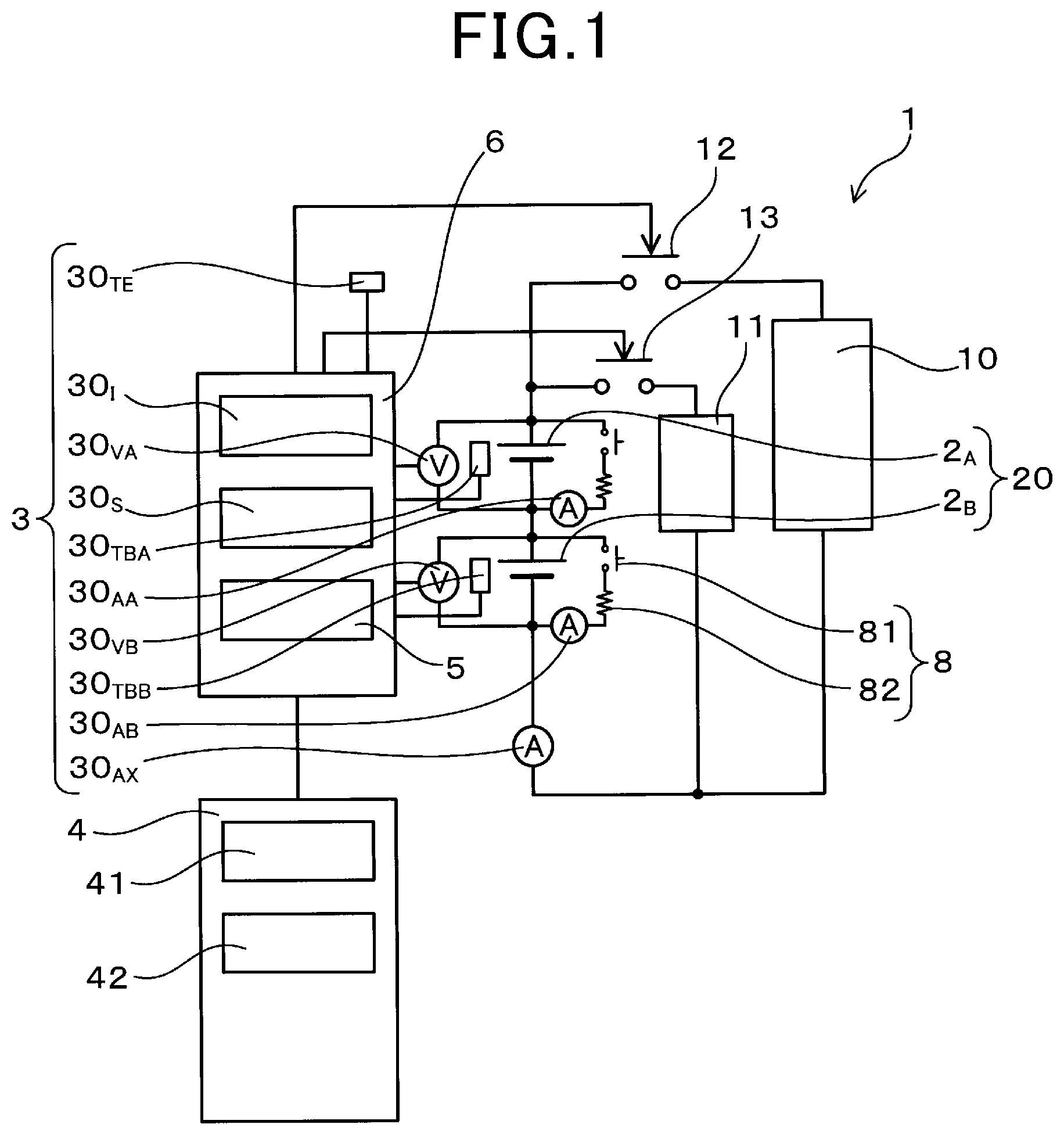
is a circuit diagram of a battery monitoring system according to a first embodiment;
is a graph of changes with time in monitoring data of a first secondary battery according to the first embodiment;
is a visualization of a partial correlation coefficient matrix Λ 1 when the first secondary battery is normal, according to the first embodiment;
is a graph of changes with time in the monitoring data of a second secondary battery according to the first embodiment;
is a visualization of a partial correlation coefficient matrix Λ 2 when the second secondary battery is normal, according to the first embodiment;
is a graph of abnormality levels when the two secondary batteries are normal, according to the first embodiment;
is a visualization of the partial correlation coefficient matrix Λ 2 when the second secondary battery has failed, according to the first embodiment;
is a graph of the abnormality levels when the second secondary battery has failed, according to the first embodiment;
is a conceptual diagram of a secondary battery during discharge, according to the first embodiment;
is a conceptual diagram of the secondary battery during charging, according to the first embodiment;
is a flowchart of processes performed by a failure determining unit according to the first embodiment;
is a flowchart following the flowchart in ;
is a circuit diagram of a battery monitoring system according to a second embodiment;
is a conceptual diagram of relationships between the abnormality levels of the secondary batteries according to the second embodiment;
is a flowchart of processes performed by a failure determining unit according to the second embodiment;
is a flowchart following the flowchart in ;
is a conceptual diagram of a battery monitoring system according to a third embodiment; and
is a conceptual graph of battery performance of the secondary battery changed with time in a first case where the the secondary battery is normal and in a second case where the secondary battery is failed.
DESCRIPTION OF THE EMBODIMENTS
The following embodiments relate to a battery monitoring system that performs fault diagnosis of a secondary battery.
A battery monitoring system that performs failure diagnosis of a secondary battery has been known. For example, in this battery monitoring system, an open circuit voltage (OCV) and a state of charge (SOC) of the secondary battery are periodically measured. The measurement values of the OCV and the SOC are then cumulatively stored. When a relationship between the OCV and the SOC that have been newly measured has significantly changed compared to a relationship between the OCV and the SOC that have been previously measured, the secondary battery is determined to have failed.
In addition, as another example of fault diagnosis, there is a method in which the capacity of the secondary battery is measured. In this case, first, the secondary battery is fully discharged. Subsequently, the secondary battery is fully charged. Then, the capacity of the secondary battery is measured through measurement of the charge amount required for charging. When the value of the capacity that has been newly measured has significantly changed compared to the value of the capacity that has been previously measured, the secondary battery is determined to have failed.
However, in the method in which the OCV and the SOC are measured, and failure determination is performed based on whether the relationship between the OCV and the SOC has changed compared to the relationship between previous measurement values, the measurement values of the OCV and the SOC are required to be cumulatively stored. As a result, the amount of data that is stored becomes large and a large-volume storage apparatus is required. Furthermore, failure determination is difficult to perform until the secondary battery has completely failed. That is, initial stage of failure of the battery is difficult to detect.
Moreover, when failure determination is performed through measurement of the capacity of the secondary battery, an issue in that a large amount of time is required for measurement of the capacity arises.
It is thus desired to provide a battery monitoring system that is capable of detecting initial stage of failure of a secondary battery, reducing an amount of data to be stored, and performing failure determination in a small amount of time.
An exemplary embodiment provides a battery monitoring system that monitors states of at least two secondary batteries. The battery monitoring system includes a data acquiring unit and a failure determining unit. The data acquiring unit acquires a plurality of types of monitoring data to monitor the state of each of the secondary batteries. The failure determining unit determines whether the secondary battery has failed. The failure determining unit includes a matrix calculating unit and an abnormality level calculating unit. The matrix calculating unit performs sparsity regularization using the acquired monitoring data of each of the secondary batteries as variables and calculates a partial correlation coefficient matrix of the monitoring data. The abnormality level calculating unit calculates, as an abnormality level, a difference in a partial correlation coefficient, which is a component of the partial correlation coefficient matrix, between two partial correlation coefficient matrices respectively calculated using the monitoring data of the two secondary batteries. The failure determining unit is configured to determine that either of the two secondary batteries has failed when the calculated abnormality level exceeds a predetermined threshold.
The failure determining unit of the above-described battery monitoring system performs sparsity regularization using the monitoring data of the secondary battery as variables and calculates the partial correlation coefficient matrix. Then, the failure determining unit calculates, as the abnormality level, the difference in the partial correlation coefficient between the two partial correlation coefficient matrices respectively calculated using the two secondary batteries. The failure determining unit determines that either of the two secondary batteries has failed when the abnormality level exceeds the threshold.
As a result, initial stage of failure of the secondary battery can be detected. That is, when sparsity regularization is performed, two types of monitoring data that have a high correlation can be selected among the plurality of types of monitoring data of the secondary battery. That is, when two types of monitoring data have a high correlation, the absolute value of the partial correlation coefficient becomes closer to 1. In addition, when two types of monitoring data have a low correlation, the absolute value of the partial correlation coefficient becomes closer to 0.
Therefore, when the two secondary batteries are compared and the partial correlation coefficients respectively included in the partial correlation coefficient matrices of the two secondary batteries significantly differ, this means that the combination of two types of monitoring data that have a high correlation differs between the two secondary batteries. Therefore, in this case, a determination that a failure of some sort has occurred in either of the two secondary batteries can be made. In particular, the partial correlation coefficient significantly changes even when an initial stage of failure occurs in the secondary battery. Therefore, initial stage of failure of the secondary battery can be detected through use of the change in the partial correlation coefficient.
In addition, the above-described battery monitoring system is capable of performing failure detection without being required to store all pieces of monitoring data acquired in the past, as long as only the pieces of monitoring data required for the calculation of the partial correlation coefficient matrices are stored. Therefore, the amount of data to be stored can be reduced. Moreover, compared to cases where the capacity of the secondary battery is measured, the above-described battery monitoring system can perform failure determination of the secondary battery in a small amount of time.
As described above, according to the above-described exemplary embodiment, a battery monitoring system that is capable of detecting initial stage of failure of a secondary battery, reducing an amount of data to be stored, and performing failure determination in a small amount of time can be provided.
First Embodiment
A first embodiment of the above-described battery monitoring system will be described with reference to to . As shown in , a battery monitoring system 1 according to the present embodiment monitors the states of at least two secondary batteries 2 ( 2 A and 2 B ). The battery monitoring system 1 includes a data acquiring unit 3 and a failure determining unit 4 . For each of the secondary batteries 2 , the data acquiring unit 3 acquires a plurality of types of monitoring data X 1 to X n that are used to monitor the state of the secondary battery 2 . The failure determining unit 4 determines whether the secondary battery 2 has failed.
The failure determining unit 4 includes a matrix calculating unit 41 and an abnormality level calculating unit 42 . For each of the secondary batteries 2 ( 2 A and 2 B ), the matrix calculating unit 41 performs sparsity regularization using the acquired monitoring data X 1 to X n as variables. The matrix calculating unit 41 thereby calculates a partial correlation coefficient matrix Λ of the monitoring data X 1 to X n . The abnormality level calculating unit 42 calculates, as an abnormality level Δ, a difference in a partial correlation coefficient λ between two partial correlation matrices Λ that have been respectively calculated using the monitoring data of the two secondary batteries 2 A and 2 B . When the calculated abnormality level Δ exceeds a predetermined threshold Δ TH , the failure determining unit 4 determines that either of the two secondary batteries 2 A and 2 B has failed.
The battery monitoring system 1 according to the present embodiment is an onboard battery monitoring system that is mounted in a vehicle, such as an electric vehicle or a hybrid vehicle. As shown in , according to the present embodiment, the two secondary batteries 2 A and 2 B are connected to each other in series and configure an assembled battery (battery pack) 20 . A load 10 and a charging apparatus 11 are connected to the assembled battery 20 . The load 10 according to the present embodiment is an inverter. Direct-current power provided by the assembled battery 20 is converted to alternating-current power through use of the inverter, and a three-phase alternating current motor (not shown) is thereby driven. As a result, the vehicle is made to drive.
A discharge switch 12 is arranged between the load 10 and the assembled battery 20 . In addition, a charging switch 13 is arranged between the charging apparatus 11 and the assembled battery 20 . A control unit 6 controls on/off operations of the switches 12 and 13 . When the assembled battery 20 is charged, the control unit 6 turns on the charging switch 13 . When the load 10 is driven, the control unit 6 turns on the discharge switch 12 .
In addition, a discharge circuit 8 is connected to each of the secondary batteries 2 . Each discharge circuit 8 is configured by an individual discharge switch 81 and a discharge resistor 82 . When the respective stage of charge (SOC) of the two secondary batteries 2 are not equal, the control unit 6 turns on the individual discharge switch 81 and individually discharges the secondary battery 2 . As a result, the respective SOC of the two secondary batteries 2 are made equal.
As the monitoring data of each secondary battery 2 , the data acquiring unit 3 according to the present embodiment acquires a closed circuit voltage (CCV), a charge current I C , a discharge current I D , the SOC, a battery temperature T B , an integrated charging time Σt c , an integrated discharge time Σt d , an integrated charge current ΣI C , an integrated discharge current ΣI D , an environmental temperature T E of the periphery, and the like of each secondary battery 2 .
The data acquiring unit 3 includes a current sensor 30 A ( 30 AA , 30 AB , and 30 AX ), a voltage sensor 30 V ( 30 VA and 30 VB ), a battery temperature sensor 30 TB ( 30 TBA and 30 TBB ), an environment temperature sensor 30 TE , an integrating unit 30 I , and a SOC calculating unit 30 S . The current sensor 30 A measures the charge current I C or the discharge current I D . The battery temperature sensor 30 TB measures the battery temperature T B . The environment temperature sensor 30 TE measures the environmental temperature T E . The voltage sensor 30 V measures the CCV and the OCV of the secondary battery 2 . The SOC calculating unit 30 S calculates the SOC of the secondary battery 2 using the measurement value of the OCV.
In addition, the integrating unit 30 I calculates an integrated temperature stress ΣT, the integrated charging time Σt c , the integrated discharge time Σt d , the integrated charge current ΣI C , and the integrated discharge current ΣI D . The integrated charging time Σt c is an integration value of a charging time t c of the secondary battery 2 . The integrated discharge time Σt d is an integration value of a discharge time t d of the secondary battery 2 . The integrated charge current ΣI C is an integration value of the charge current I C . Furthermore, the integrated temperature stress ΣT is an integration value of an amount of time at each temperature during use. For example, the integrated temperature stress ΣT can be calculated in the following manner: {10° C.×time}+{15° C.×time}+ . . . +{45° C.×time}. In addition, because a greater amount of stress is applied to the secondary battery 2 as the temperature increases, weight may be applied to the amounts of time. The method for calculating the integrated temperature stress ΣT is not limited thereto. For example, a method in which only the amounts of time at which the temperature is 40° C. or higher are counted and integrated can also be used.
The battery monitoring system 1 according to the present embodiment also includes a storage unit 5 . The storage unit 5 stores therein the pieces of monitoring data required for calculation of the above-described partial correlation coefficient matrices Λ and the calculated partial correlation coefficient matrices Λ.
In addition, according to the present embodiment, a lithium battery is used as each of the secondary batteries 2 A and 2 B . The structures of the secondary batteries 2 A and 2 B , and the materials used for electrodes and the like are the same.
Next, the structure of the secondary battery 2 will be described in further detail. As shown in , the secondary battery 2 includes a positive electrode 21 P , a negative electrode 21 N , a separator 24 , and an electrolyte 25 . The separator 24 is disposed between the positive electrode 21 P and the negative electrode 21 N . The positive electrode 21 P and the negative electrode 21 N each include a metal current collector 23 ( 23 P and 23 N ) and an active material 22 ( 22 P and 22 N ) that is attached to the current collector 23 .
As shown in , when the SOC of the secondary battery 2 is substantially 100%, most of the lithium ions are present in the active material 22 N of the negative electrode 21 N . When discharge is performed, the lithium ions move to the active material 22 P of the positive electrode 21 P . In addition, as shown in , when the SOC of the secondary battery 2 is substantially 0%, most of the lithium ions are present in the active material 22 P of the positive electrode 21 P . When charging is performed, the lithium ions move to the active material 22 N of the negative electrode 21 N .
When an external impact or the like is applied to the secondary battery 2 , failure may occur in the secondary battery 2 . For example, the respective current collector 23 ( 23 P and 23 N ) of the electrodes 21 ( 21 P and 21 N ) may come into contact with each other. Alternatively, the active material 22 may separate from the current collector 23 . Furthermore, when the secondary battery 2 is used for a long period of time, deposition of metallic lithium into the electrolyte 25 may occur and short-circuiting between the pair of electrodes 21 may occur. The failure determining unit 4 according to the present embodiment determines whether such failures have occurred in the secondary battery 2 .
Next, a method for performing the fault diagnosis of the secondary battery 2 will be described with reference to to . Here, as shown in , a case in which six types of monitoring data X 1 to X 6 are used will be described. For example, first monitoring data X 1 is the CCV. Second monitoring data X 2 is the discharge current I D . Third monitoring data X 3 is the SOC. Fourth monitoring data X 4 is the battery temperature T B . Fifth monitoring data X 5 is the integrated discharge time Σt D . Sixth monitoring data X 6 is the integrated discharge current ΣI D . Other types of monitoring data X may also be used. The order of the types of monitoring data X is arbitrary. Furthermore, although six types of monitoring data X 1 to X 6 are used in and the like, the present disclosure is not limited thereto. Two or more types of monitoring data X may be used.
As shown in , the value of each of the monitoring data X 1 to X 6 changes with the passage of time. First, the failure determining unit 4 performs sparsity regularization using the monitoring data X 1 to X 6 of the first secondary battery 2 A (see ) as the variables. The failure determining unit 4 thereby calculates a first partial correlation coefficient matrix Λ 1 . For example, the first partial coefficient matrix Λ 1 can be expressed in the following manner.
In the expression above, λ 12 denotes a partial correlation coefficient between the monitoring data X 1 and the monitoring data X 2 . In addition, because the partial correlation coefficient matrix Λ is a symmetric matrix, some of the partial correlation coefficients λ are omitted in the expression above. Furthermore, because the components on a main diagonal in the partial correlation coefficient matrix Λ are all 1, these components are omitted in the description.
When the correlation between two types of monitoring data is high, the partial correlation coefficient λ becomes closer to 1 or −1. In addition, when the correlation is low, the partial correlation coefficient λ becomes closer to 0. shows a visualization of the first partial correlation coefficient matrix Λ 1 . As shown in , two types of monitoring data X that have a high correlation (such as X 2 and X 6 , and X 5 and X 6 ) are indicated by a relatively thick line. In addition, two types of monitoring data X that have a lower correlation (such as X 3 and X 6 ) are indicated by a slightly thinner line.
Next, the failure determining unit 4 performs sparsity regularization again using monitoring data X′ 1 to X′ 6 of the second secondary battery 2 B (see ). The failure diagnosing unit 5 thereby calculates a second partial correlation coefficient matrix Λ 2 . As shown in , the values of the monitoring data X′ 1 to X′ 6 of the second secondary battery 2 B change with the passage of time. According to the present embodiment, the two partial coefficient matrices Λ 2 and Λ 2 are respectively calculated through use of the monitoring data X 1 to X 6 and the monitoring data X′ 1 to X′ 6 that are acquired at a same time t 1 (see and ). For example, the second partial coefficient matrix Λ 2 can be expressed in the following manner.
shows a visualization of the second partial correlation coefficient matrix Λ 2 . When the two secondary batteries 2 A and 2 B are both normal, the correlations between the monitoring data X 1 to X 6 of the first secondary battery 2 A and the correlations between the monitoring data X′ 1 to X′ 6 of the second secondary battery 2 B are substantially identical. Therefore, the two partial correlation coefficient matrices Λ 1 and Λ 2 are substantially identical. Thus, graphs (see and ) respectively visualizing the two partial correlation coefficient matrices Λ 1 and Λ 2 are substantially identical.
After calculating the two partial correlation coefficient matrices Λ 1 and Λ 2 in such a manner, the failure determining unit 4 calculates the difference in the partial correlation coefficient λ between the two partial correlation coefficient matrices Λ 1 and Λ 2 as the abnormality level Δ. For example, the abnormality level Δ can be expressed in the following manner.
Δ 12 = λ 12 ′ - λ 12 Δ 13 = λ 13 ′ - λ 13 ⋮ Δ 56 = λ 56 ′ - λ 56 [ Formula 3 ]
Here, Δ 12 denotes an abnormality level Δ of the partial correlation coefficient λ 12 between the two partial correlation coefficient matrices Λ 1 and Λ 2 .
shows a graph of each of the abnormality levels Δ. As described above, when the correlations between the monitoring data X 1 to X 6 of the first secondary battery 2 A and the correlations between the monitoring data X′ 1 to X′ 6 of the second secondary battery 2 B have not significantly changed, the two calculated partial correlation coefficient matrices Λ 1 and Λ 2 are substantially identical. Therefore, the amount of change in the partial correlation coefficient λ is small, and the abnormality level Δ is a small value. When all abnormality levels Δ are less than the threshold Δ TH , the failure determining unit 4 determines that the correlations between the monitoring data X of the two secondary batteries 2 A and 2 B are identical, that is, neither of the two secondary batteries 2 A and 2 B has failed.
Next, shows a graph that is a visualization of the partial correlation coefficient matrix Λ 2 when the second secondary battery 2 B has failed. In this graph, compared to that in , the correlation between the monitoring data X′ 3 and the monitoring data X′ 5 and the correlation between the monitoring data X′ 3 and the monitoring data X′ 6 are low at substantially 0.
shows a graph of the abnormality levels Δ at this time. As shown in , the abnormality level Δ 35 of the monitoring data X 3 and the monitoring data X 5 , and the abnormality level Δ 36 of the monitoring data X 3 and the monitoring data X 6 are high. When the calculated abnormality level Δ exceeds the threshold Δ TH , the failure determining unit 4 determines that the correlations between the monitoring data X 1 to X 6 differ between the two secondary batteries 2 A and 2 B , that is, either of the two secondary batteries 2 A and 2 B has failed. More specifically, the failure determining unit 4 determines that one of the secondary batteries 2 A and 2 B has failed when at least one abnormality level Δ among the plurality of calculated abnormality levels Δ 12 to Δ 56 exceeds the threshold Δ TH .
Next, a flowchart of the processes performed by the failure determining unit 4 will be described. As shown in , the failure determining unit 4 according to the present embodiment performs steps S 1 and S 2 and steps S 3 and S 4 in parallel. At step S 1 , the failure determining unit 4 measures the monitoring data X 1 to X n of the first secondary battery 2 A in a fixed period. Then, the failure determining unit 4 proceeds to step S 2 . Here, the failure determining unit 4 calculates the first partial correlation coefficient matrix Λ 1 using the measured monitoring data X 1 to X n .
In addition, at step S 3 , the failure determining unit 4 measures the monitoring data X′ 1 to X′ n of the second secondary battery 2 B in a fixed period. Then, the failure determining unit 4 proceeds to step S 4 . Here, the failure determining unit 4 calculates the second partial correlation coefficient matrix Λ 2 using the measured monitoring data X′ 1 to X′ n .
After calculating the two partial correlation coefficient matrices Λ 1 and Λ 2 in the manner described above, the failure determining unit 4 proceeds to step S 5 . At step S 5 , the failure determining unit 4 calculates the abnormality levels Δ using the two partial correlation coefficient matrices Λ 1 and Λ 2 . Next, the failure determining unit 4 proceeds to step S 6 and determines whether at least one of the calculated plurality of abnormality levels Δ (see ) exceeds the threshold Δ TH . When a YES determination is made at step S 6 (see ), the failure determining unit 4 proceeds to step S 7 and determines that either of the two secondary batteries 2 A and 2 B has failed. In addition, when a NO determination is made at step S 6 , the failure determining unit 4 returns to steps S 1 and S 3 .
Next, working effects according to the present embodiment will be described. The failure determining unit 4 according to the present embodiment performs sparsity regularization using the monitoring data of the secondary battery 2 as variables and calculates the partial correlation coefficient matrix Λ. Then, the failure determining unit 4 calculates, as the abnormality level Δ, the difference in the partial correlation coefficient λ between the two partial correlation coefficient matrices Λ 1 and Λ 2 respectively calculated using the two secondary batteries 2 A and 2 B. When the abnormality level Δ exceeds the threshold Δ TH , the failure determining unit 4 determines that the either of the two secondary batteries 2 A and 2 B has failed.
As a result, initial stage of failure of the secondary battery 2 can be detected.
shows battery performance of the secondary battery changed with time in a first case where the the secondary battery is normal and in a second case where the secondary battery is failed. The battery performance may include a capacity of the the secondary battery or a resistance of the secondary battery.
In the conventional technique, it is difficult to perform failure determination at an initial stage of failure of the secondary battery in the second case, shown in , where the secondary battery is completely failed. Thus, the failure determination cannot be performed at the initial stage of failure of the secondary battery when the battery performance is significantly reduced. In other words, the initial stage of failure of the secondary battery cannot be detected.
In the present embodiment, it is possible to perform failure determination at an initial stage of failure of the secondary battery in the second case, shown in , where the secondary battery is completely failed. Thus, the failure determination can be performed at the initial stage of failure of the secondary battery when the battery performance is significantly reduced. In other words, the initial stage of failure of the secondary battery can be detected.
That is, as described above, when sparsity regularization is performed, two types of monitoring data that have a high correlation can be selected among the plurality of types of monitoring data of the secondary battery 2 . That is, when two types of monitoring data have a high correlation, the absolute value of the partial correlation coefficient λ becomes closer to 1. In addition, when two types of monitoring data X have a low correlation, the absolute value of the partial correlation coefficient λ becomes closer to 0.
Therefore, when the two secondary batteries 2 A and 2 B are compared and the partial correlation coefficients λ respectively included in the partial correlation coefficient matrices Λ 1 and Λ 2 of the secondary batteries 2 A and 2 B significantly differ, this means that the combination of two types of monitoring data that have a high correlation differs between the two secondary batteries 2 A and 2 B . Therefore, in this case, a determination that a failure of some sort has occurred in either of the two secondary batteries 2 A and 2 B can be made. In particular, the partial correlation coefficient λ significantly changes even when an initial stage of failure occurs in the secondary battery 2 . Therefore, initial stage of failure of the secondary battery 2 can be detected through use of the change in the partial correlation coefficient λ.
In addition, the battery monitoring system 1 according to the present embodiment is capable of performing failure detection without being required to store all pieces of monitoring data acquired in the past, as long as only the pieces of monitoring data required for the calculation of the partial correlation coefficient matrices Λ are stored. Therefore, the amount of data to be stored can be reduced. Moreover, compared to cases where the capacity of the secondary battery 2 is measured, the battery monitoring system 1 according to the present embodiment can perform failure determination of the secondary battery 2 in a small amount of time.
In addition, as shown in and , the matrix calculating unit 41 according to the present embodiment is configured to calculate the plurality of partial correlation coefficient matrices Λ 1 and Λ 2 using the monitoring data X 1 to X 6 and X′ 1 to X′ 6 acquired at the same time t 1 .
Therefore, the two secondary batteries 2 A and 2 B at the same time period can be compared, and failure determination can be accurately performed.
Furthermore, as shown in , according to the present embodiment, the assembled battery 20 is configured by the two secondary batteries 2 A and 2 B being connected in series.
As a result, failure determination of each secondary battery 2 can be performed through use of the plurality of secondary batteries 2 A and 2 B configuring the assembled battery 20 .
As described above, according to the present embodiment, a battery monitoring system that is capable of detecting initial stage of failure of a secondary battery, reducing an amount of data to be stored, and performing failure determination in a small amount of time can be provided.
In and the like, a 6×6 partial correlation coefficient matrix Λ is calculated through use of the six types of monitoring data X 1 to X 6 . The plurality of abnormality levels Δ 12 to Δ 56 (see ) are calculated based on the monitoring data X 1 to X 6 . When at least one abnormality level Δ among the plurality of abnormality levels Δ 12 to Δ 56 exceeds the threshold Δ TH , the secondary battery 2 is determined to have failed. However, the present disclosure is not limited thereto. That is, a 2×2 partial correlation coefficient matrix Λ may be calculated through use of two types of monitoring data X 1 and X 2 . Only a single abnormality level Δ 12 may then be calculated based on the monitoring data X 1 and X 2 .
According to the embodiments below, reference numbers used in the drawings that are the same as those used according to the first embodiment denote constituent elements and the like that are similar to those according to the first embodiment, unless otherwise indicated.
Second Embodiment
According to a second embodiment, an example in which the quantity of the secondary batteries 2 and the like are modified is given. As shown in , according to the present embodiment, three secondary batteries 2 A to 2 C are connected in series. In addition, the data acquiring unit 2 acquires the monitoring data of each of the secondary batteries 2 A to 2 C . In a manner similar to that according to the first embodiment, the data acquiring unit 3 includes the voltage sensor 30 V ( 30 VA , 30 VB , and 30 VC ), the current sensor 30 A ( 30 AA , 30 AB , 30 AC , and 30 AX ), the temperature sensor 30 TB ( 30 TBA , 30 TBB , and 30 TBC ), and the like.
The matrix calculating unit 41 calculates the respective partial correlation coefficient matrices Λ of the three secondary batteries 2 A , 2 B , and 2 C . In addition, the failure determining unit 4 includes a failure identifying unit 43 . The failure identifying unit 43 identifies the failed secondary battery 2 using the abnormality levels Δ between the secondary batteries 2 .
For example, as shown in , a following case is assumed. That is, the abnormality level Δ AB between the first secondary battery 2 A and the second secondary battery 2 B is higher than the threshold Δ TH . The abnormality level Δ BC between the second secondary battery 2 B and the third secondary battery 2 C is higher than the threshold Δ TH . The abnormality level Δ AC between the first secondary battery 2 A and the third secondary battery 2 C is lower than the threshold Δ TH . In this case, the abnormality levels Δ AB and Δ BC of the second secondary battery 2 B in relation to the other secondary batteries 2 (that is, the first secondary battery 2 A and the third secondary battery 2 C ) are both higher than the threshold Δ TH . Therefore, the second secondary battery 2 B can be identified as having failed.
Next, a flowchart of the processes performed by the failure determining unit 4 will be described. As shown in , the failure determining unit 4 performs steps S 11 to S 16 in parallel. At step S 11 , the failure determining unit 4 measures the monitoring data of the first secondary battery 2 A in a fixed period. Then, the failure determining unit 4 proceeds to step S 12 and calculates the first partial correlation coefficient matrix Λ 1 using the measured monitoring data.
In a similar manner, at step S 13 , the failure determining unit 4 measures the monitoring data of the second secondary battery 2 B . Then, the failure determining unit 4 proceeds to step S 14 and calculates the second partial correlation coefficient matrix Λ 2 using the measured monitoring data. Furthermore, at step S 15 , the failure determining unit 4 measures the monitoring data of the third secondary battery 2 C . Then, the failure determining unit 4 proceeds to step S 16 and calculates the third partial correlation coefficient matrix Λ 3 using the measured monitoring data.
After calculating the three partial correlation coefficient matrices Λ in the manner described above, the failure determining unit 4 calculates the abnormality levels Δ between the secondary batteries 2 . That is, the failure determining unit 4 calculates the abnormality level Δ AB (refer to Formula 3, above) using the partial correlation coefficient matrix Λ 1 of the first secondary battery 2 A and the partial correlation coefficient matrix Λ 2 of the second secondary battery 2 B . In a similar manner, the failure determining unit 4 calculates the abnormality level Δ BC between the second secondary battery 2 B and the third secondary battery 2 C . Furthermore, the failure determining unit 4 calculates the abnormality level Δ AC between the first secondary battery 2 A and the third secondary battery 2 C .
Subsequently, the failure determining unit 4 proceeds to step S 18 . Here, the failure determining unit 4 determines whether any of the abnormality levels Δ AB , Δ BC , and Δ AC exceeds the threshold Δ TH . When a NO determination is made at step S 18 , the failure determining unit 4 returns to step S 11 . In addition, when a YES determination is made at step S 18 , the failure determining unit proceeds to step S 19 . Here, the failure determining unit 4 determines the secondary battery 2 of which all abnormality levels Δ are higher than the threshold Δ TH . Then, the failure determining unit proceeds to step S 20 . Here, the failure determining unit 4 determines that the identified secondary battery 2 has failed.
Working effects according to the present embodiment will be described. According to the present embodiment, the respective partial correlation coefficient matrices Λ are calculated for the three secondary batteries 2 A , 2 B , and 2 C . In addition, the failure identifying unit 43 identifies the failed secondary battery 2 using the abnormality levels Δ AB , Δ BC , and Δ AC between the secondary batteries 2 A , 2 B , and 2 C .
When the two secondary batteries 2 A and 2 B are used as according to the first embodiment, when the abnormality level Δ exceeds the threshold Δ TH , the secondary battery 3 that has failed cannot be identified. However, when the three secondary batteries 2 A , 2 B , and 2 C are used as according to the present embodiment, the secondary battery of which all abnormality levels Δ exceed the threshold Δ TH can be identified as having failed.
Furthermore, according to the present embodiment, configurations and working effects similar to those according to the first embodiment are also provided.
According to the present embodiment, three secondary batteries 2 B , and 2 C are used. However, the present disclosure is not limited thereto. Four or more secondary batteries 2 may be used.
Third Embodiment
According to a third embodiment, an example in which the arrangement positions of the secondary batteries 2 are modified is given. As shown in , the plurality of secondary batteries 2 ( 2 B , and 2 C ) are mounted in separate vehicles 7 . The data acquiring unit 3 that acquires the monitoring data of the secondary battery 2 is mounted in each vehicle 7 .
The failure determining unit 4 and the storage unit 5 are provided in an external apparatus 8 (such as a server). A transmission/reception apparatus 71 that transmits and receives data is mounted in each vehicle 7 . The monitoring data is transmitted to the external apparatus 8 through use of the transmission/reception apparatus 7 . The failure determining unit 4 calculates the partial correlation coefficient matrices Λ and the abnormality levels Δ using the transmitted monitoring data. Then, in a manner similar to that according to the second embodiment, the failure determining unit 4 identifies the failed secondary battery 2 using the calculated abnormality levels Δ.
Working effects according to the present embodiment will be described. According to the present embodiment, the secondary batteries 2 are mounted in separate vehicles 7 .
As a result, failure determination of each secondary battery 2 can be performed through use of the secondary battery 2 that is mounted in each vehicle 7 . Therefore, failure determination can be performed even when only a single secondary battery 2 is mounted in each vehicle 7 .
In addition, when the secondary battery 2 is monitored in only a single vehicle 7 and only a single system of the data acquiring unit 3 is provided, if the data acquiring unit 3 fails, the monitoring data may appear to have not changed. In this case, failures in the secondary battery 2 and the data acquiring unit 3 may not be accurately detected.
In this regard, when the secondary battery 2 and the data acquiring unit 3 are provided in each vehicle 7 as according to the present embodiment, because a plurality of systems of the data acquiring unit 3 are present, if the data acquiring unit 3 of any of the vehicles 7 fails, the failure in the data acquiring unit 3 can be detected. That is, as a result of the secondary batteries 2 and the data acquiring units 3 being arranged to be dispersed among the vehicles 7 , and the secondary batteries 2 being mutually monitored as according to the present embodiment, failure determination of a power supply system including the data acquiring unit 3 (sensors) can be performed.
Furthermore, according to the present embodiment, configurations and working effects similar to those according to the first embodiment are also provided.
The present disclosure is not limited to the above-described embodiments. Various embodiments are applicable without departing from the spirit of the present disclosure.
Figures (18)
Citations
This patent cites (20)
- US9237459
- US2004/0251875
- US2013/0015982
- US2015/0048838
- US2015/0149015
- US2016/0169978
- US2016/0252586
- US2018/0270132
- US2018/0285317
- US2018/0348728
- US2018/0357539
- US2019/0018397
- US2019/0265309
- US2019/0310321
- US2020/0342359
- US2020/0380371
- US2016-152704
- US2017-138241
- US2017-139911
- US2019-152656