Pipe Branching Device and Compressor
Abstract
This pipe branching device is provided with a main pipe and a branch pipe branching off from the main pipe. The main pipe includes a first pipe and a second pipe fitted into the first pipe in an axial direction of the first pipe. A chamber communicating with the branch pipe is provided between the first pipe and the second pipe. A flow path communicating with the chamber from the inside of the second pipe is provided.
Claims (8)
1. A pipe branching device comprising: a main pipe; and a branch pipe that branches off from the main pipe, wherein the main pipe includes a first pipe and a second pipe that is fitted to the first pipe in an axial direction of the first pipe, a chamber that communicates with the branch pipe is provided between the first pipe and the second pipe, and a flow channel that communicates with the chamber is provided from an inside of the second pipe, wherein the flow channel is defined by an expansion portion that is provided at any one of the first pipe and the second pipe and that expands toward the other, and an inclined portion that is provided at an end portion of the other of the first pipe and the second pipe and that has a thickness decreasing toward the expansion portion, wherein an abutment part that abuts against the expansion portion is provided at a position of the end portion which is different from the inclined portion in a circumferential direction.
8. A pipe branching device comprising: a main pipe; and a branch pipe that branches off from the main pipe, wherein the main pipe includes a first pipe and a second pipe that is fitted to the first pipe in an axial direction of the first pipe, a chamber that communicates with the branch pipe is provided between the first pipe and the second pipe, and a flow channel that communicates with the chamber is provided from an inside of the second pipe, wherein the first pipe has an outer periphery-side end portion that is provided on an outer side of the second pipe and to which the second pipe is fitted, and an inner periphery-side end portion that is provided on an inner side of the second pipe and that configures a double pipe together with the outer periphery-side end portion, and the flow channel is a hole or a slit provided in the inner periphery-side end portion.
Show 6 dependent claims
2. The pipe branching device according to claim 1 , wherein the inclined portion is provided on an entire periphery of the end portion in a circumferential direction.
3. The pipe branching device according to claim 1 , wherein a branching position of the branch pipe is provided on an upstream side of the flow channel in a flowing direction of a main flow flowing in the main pipe.
4. The pipe branching device according to claim 1 , wherein a flow channel sectional area of the flow channel is the same as a flow channel sectional area of the branch pipe.
5. The pipe branching device according to claim 1 , wherein the flow channel is a hole or a slit provided in the second pipe.
6. A compressor comprising: the pipe branching device according to claim 1 , wherein the second pipe is an outlet pipe.
7. A compressor comprising: the pipe branching device according to claim 1 , wherein the second pipe is an inlet pipe.
Full Description
Show full text →
TECHNICAL FIELD
The present disclosure relates to a pipe branching device and a compressor.
This application claims priority based on Japanese Patent Application No. 2021-100383 filed on Jun. 16, 2021, the entire disclosure of which is incorporated herein.
BACKGROUND ART
In a fluid machine such as a turbo machine, a configuration where a main flow is extracted using a branch pipe is adopted for controllability improvement. In such a configuration, when a valve is provided in the middle of the branch pipe, a pressure loss caused by inflow of the main flow into the branch pipe occurs.
In order to reduce the pressure loss caused by the inflow of the main flow into the branch pipe, a patent literature 1 discloses a valve body fitted to a diversion hole provided in a scroll part. Such a valve body is configured such that an inner surface along an inner wall of the scroll part in a closed state is formed.
CITATION LIST
Patent Literature
[PTL 1] International Publication No. WO2012/157598
SUMMARY OF INVENTION
Technical Problem
However, in the configuration of the related art described in PTL 1, it is necessary to design a layout and a shape of the valve body for each specification of a compressor housing (fluid machine), and thereby the configuration is not suitable for mass production.
The present disclosure is devised in view of the problem described above, and an object thereof is to provide a pipe branching device and a compressor that are suitable for mass production.
Solution to Problem
According to an aspect of the present disclosure, in order to achieve the object, there is provided a pipe branching device including:
•
• a main pipe; and a branch pipe that branches off from the main pipe, • in which the main pipe includes a first pipe and a second pipe that is fitted to the first pipe in an axial direction of the first pipe, • a chamber that communicates with the branch pipe is provided between the first pipe and the second pipe, and • a flow channel that communicates with the chamber is provided from an inside of the second pipe.
Advantageous Effects of Invention
With the pipe branching device of the present disclosure, it is not necessary to design a layout and a shape of a valve body for each specification of a fluid machine, and the pipe branching device suitable for mass production can be provided.
BRIEF DESCRIPTION OF DRAWINGS
is a longitudinal sectional view schematically showing a pipe branching device according to embodiment 1.
is a sectional view taken along line II-II of the pipe branching device shown in .
is a sectional view taken along line III-III of the pipe branching device shown in .
is a view showing a modification example of a branch pipe of the pipe branching device shown in .
is a longitudinal sectional view schematically showing modification example 1 of the pipe branching device according to embodiment 1.
is a longitudinal sectional view schematically showing modification example 2 of the pipe branching device according to embodiment 1.
is a longitudinal sectional view schematically showing modification example 3 of the pipe branching device according to embodiment 1.
is a perspective view schematically showing an outer shape of a compressor that has adopted the pipe branching device according to embodiment 1.
is a longitudinal sectional view schematically showing a pipe branching device according to embodiment 2.
is a sectional view taken along line X-X of the pipe branching device shown in .
is a sectional view taken along line XI-XI of the pipe branching device shown in .
is a view showing a modification example of a flow channel of the pipe branching device shown in .
is a longitudinal sectional view schematically showing modification example 1 of the pipe branching device according to embodiment 2.
is a longitudinal sectional view schematically showing modification example 2 of the pipe branching device according to embodiment 2.
is a longitudinal sectional view schematically showing modification example 3 of the pipe branching device according to embodiment 2.
is a perspective view schematically showing an outer shape of a compressor that has adopted the pipe branching device according to embodiment 2.
DESCRIPTION OF EMBODIMENTS
Hereinafter, a pipe branching device and a compressor according to an embodiment of the present disclosure will be described with reference to the accompanying drawings. However, dimensions, materials, shapes, relative dispositions, and the like of components described in the embodiment or shown in the drawings are not intended to limit the scope of the present invention but are merely explanatory examples.
The pipe branching device according to the embodiment can be adopted for general fluid machines such as a turbo machine and is suitable for, for example, a compressor of a turbocharger as will be described later.
Embodiment 1
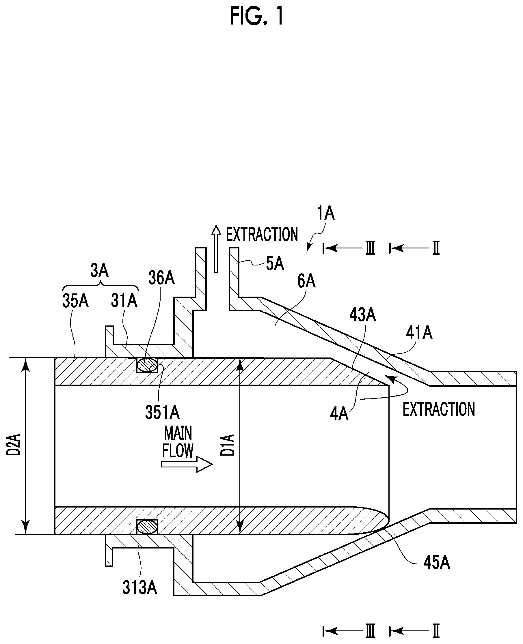
is a longitudinal sectional view schematically showing a pipe branching device 1 A according to embodiment 1. is a sectional view taken along line II-II of the pipe branching device 1 A shown in , and is a sectional view taken along line III-III of the pipe branching device 1 A shown in .
As shown in , the pipe branching device 1 A according to embodiment 1 is a pipe branching device including a main pipe 3 A and a branch pipe 5 A that branches off from the main pipe 3 A.
The main pipe 3 A includes a first pipe 31 A and a second pipe 35 A that is fitted to the first pipe 31 A in an axial direction of the first pipe 31 A. For example, the first pipe 31 A and the second pipe 35 A are circular pipes, and standard products defined in Japanese Industrial Standards (JIS) can be adopted.
In the example shown in , in a flowing direction of a main flow flowing in the main pipe 3 A, the first pipe 31 A is disposed on a downstream side, and the second pipe 35 A is disposed on an upstream side. In addition, in the example shown in , a ring groove 351 A having a rectangular section is provided in the second pipe 35 A, and the second pipe 35 A and the first pipe 31 A are sealed with an O-ring 36 A fitted to the ring groove 351 A.
A chamber 6 A that communicates with the branch pipe 5 A is provided between the first pipe 31 A and the second pipe 35 A, and a flow channel 4 A that communicates with the chamber 6 A is provided from an inside of the second pipe 35 A. The chamber 6 A is a space provided between the first pipe 31 A and the second pipe 35 A and is provided over, for example, the entire outer periphery of the second pipe 35 A. With such a configuration, a fluid that has branched off from a main flow flowing in the main pipe 3 A flows in the branch pipe 5 A through the flow channel 4 A and the chamber 6 A.
With such a configuration, the pipe branching device 1 A suitable for mass production can be provided.
The flow channel 4 A is defined by an expansion portion 41 A and an inclined portion 43 A. The expansion portion 41 A is provided at the first pipe 31 A and gradually expands toward the second pipe 35 A. The inclined portion 43 A is provided at an end portion of the second pipe 35 A. The thickness of the inclined portion 43 A on a pipeline side gradually decreases toward the expansion portion 41 A. For example, an inner peripheral surface of the expansion portion 41 A is configured by a tapered surface that expands at a constant rate toward the second pipe 35 A, and a surface of the inclined portion 43 A facing the expansion portion 41 A is configured by an inclined surface or a tapered surface that is inclined at a constant rate toward the expansion portion 41 A.
With such a configuration, since the flow channel 4 A that communicates with the chamber 6 A is defined between the inclined portion 43 A and the expansion portion 41 A, a pressure loss caused by inflow of a main flow into the chamber 6 A can be reduced. Thus, as in a valve body fitted to a diversion hole provided in a scroll part, it is not necessary to design a layout and a shape of the valve body for each specification of a fluid machine (for example, a compressor housing), and the pipe branching device 1 A suitable for mass production can be provided.
In the pipe branching device 1 A according to embodiment 1, a branching position of the branch pipe 5 A is provided on the upstream side of the flow channel 4 A provided between the inclined portion 43 A and the expansion portion 41 A in the flowing direction of a main flow flowing in the main pipe 3 A.
With such a configuration, a flow of a fluid in the branch pipe 5 A for extracting some of the main flow flowing in the main pipe 3 A flows back to the main flow at an acute angle. Thus, inflow of the main flow into the chamber 6 A can be suppressed, and a pressure loss caused by the inflow of the main flow into the chamber 6 A can be reduced.
As shown in , in the pipe branching device 1 A according to embodiment 1, the first pipe 31 A and the second pipe 35 A are circular pipes, a fitting portion 313 A to which the second pipe 35 A is fitted is provided at an inlet side end portion of the first pipe 31 A, and the second pipe 35 A and the first pipe 31 A are sealed at the fitting portion 313 A. Thus, an inner diameter D 1 A of the fitting portion 313 A provided at the inlet side end portion of the first pipe 31 A is the same as an outer diameter D 2 A of a fitting portion provided at an outlet side end portion of the second pipe 35 A.
As shown in to 3 , in the pipe branching device 1 A according to embodiment 1, an abutment part 45 A that abuts against the expansion portion 41 A is provided at a position of the end portion of the second pipe 35 A which is different from the inclined portion 43 A in a circumferential direction. As shown in , for example, the inclined portion 43 A is provided at each of positions that equally divide the end portion of the second pipe 35 A in the circumferential direction, and the abutment part 45 A is provided in an entire area between the inclined portions 43 A. In the example shown in , the inclined portion 43 A is provided at each of positions that equally divide the end portion of the second pipe 35 A into three parts in the circumferential direction, and the abutment part 45 A is provided in the entire area between the inclined portions 43 A. A tip portion of the abutment part 45 A is formed to have, for example, a cross section having a semi-arc shape.
With such a configuration, as the abutment part 45 A abuts against the expansion portion 41 A, the flow channel 4 A can be provided only between the inclined portion 43 A and the expansion portion 41 A.
In the pipe branching device 1 A according to embodiment 1, a flow channel sectional area of the flow channel 4 A is the same as a flow channel sectional area of the branch pipe 5 A. For example, as shown in , in a case where the inclined portion 43 A is provided at each of the positions that equally divide the end portion of the second pipe 35 A into three parts in the circumferential direction and the flow channel 4 A is provided between the inclined portion 43 A and the expansion portion 41 A, a total flow channel sectional area of the three flow channels 4 A is the same as the flow channel sectional area of the branch pipe 5 A.
With such a configuration, the speed of a fluid extracted from the main pipe 3 A to the branch pipe 5 A can be made constant.
As described above, the branch pipe branches off from the main pipe 3 A and extends, for example, to a radial outer side of the main pipe 3 A as shown in , but may extend, as shown in , in a tangential direction of the chamber 6 A that is provided between the first pipe 31 A and the second pipe 35 A and that is formed in an annular shape.
to 7 are longitudinal sectional views schematically showing pipe branching devices 1 A 1 to 1 A 3 according to modification examples of the pipe branching device 1 A according to embodiment 1. As shown in to 7 , the flow channel 4 A is a hole 352 A, a long hole 353 A, or a slit 354 A provided in the second pipe 35 A.
As shown in , in the pipe branching device 1 A 1 according to modification example 1, the flow channel 4 A is the hole 352 A provided in the second pipe 35 A. There are one or two or more (plurality of) holes 352 A, and the holes 352 A are configured by, for example, inclined holes gradually inclined to the downstream side in the flowing direction of a main flow from the radial outer side toward a radial inner side of the second pipe 35 A. In a case where there are two or more holes 352 A, the holes 352 A may be staggered in an axial direction of the second pipe 35 A. In addition, although not specifically shown, the holes 352 A may be holes provided in one row in the axial direction of the second pipe 35 A or may be holes provided in one row (in total, two rows) on each of both sides in a radial direction of the second pipe 35 A. With such a configuration, the pipe branching device 1 A 1 suitable for mass production can be provided.
In addition, in the pipe branching device 1 A 1 according to modification example 1, the branching position of the branch pipe 5 A is provided on the upstream side of the hole 352 A provided in the second pipe 35 A in the flowing direction of a main flow flowing in the main pipe 3 A. With such a configuration, a flow of a fluid in the flow channel 4 A for extracting some of the main flow flowing in the main pipe 3 A flows back to the main flow. Thus, inflow of the main flow into the flow channel 4 A can be suppressed, and a pressure loss caused by the inflow of the main flow into the chamber 6 A can be reduced.
As shown in , in the pipe branching device 1 A 2 according to modification example 2, the flow channel 4 A is the long hole 353 A provided in the second pipe 35 A. There are one or two or more (plurality of) long holes 353 A, and the long holes 353 A are configured by, for example, inclined holes gradually inclined to the downstream side in the flowing direction of a main flow from the radial outer side toward the radial inner side of the second pipe 35 A. In a case where there are two or more long holes 353 A, the long holes 353 A are provided at positions of the second pipe 35 A that equally divide the end portion of the second pipe 35 A in the circumferential direction.
In addition, in the pipe branching device 1 A 2 according to modification example 2, the branching position of the branch pipe 5 A is provided on the upstream side of the long hole 353 A provided in the second pipe 35 A in the flowing direction of a main flow flowing in the main pipe 3 A. With such a configuration, a flow of a fluid in the flow channel 4 A for extracting some of the main flow flowing in the main pipe 3 A flows back to the main flow. Thus, inflow of the main flow into the flow channel 4 A can be suppressed, and a pressure loss caused by the inflow of the main flow into the chamber 6 A can be reduced.
As shown in , in the pipe branching device 1 A 3 according to modification example 3, the flow channel 4 A is the slit 354 A provided in the end portion of the second pipe 35 A. There are one or two or more (plurality of) slits 354 A, and in a case where there are two or more slits 354 A, the slits 354 A are provided at, for example, positions of the second pipe 35 A that equally divide the end portion of the second pipe 35 A in the circumferential direction.
In addition, in the pipe branching device 1 A 3 according to modification example 3, the branching position of the branch pipe 5 A is provided on the upstream side of the slit 354 A provided in the second pipe 35 A in the flowing direction of a main flow flowing in the main pipe 3 A. With such a configuration, a flow of a fluid in the flow channel 4 A for extracting some of the main flow flowing in the main pipe 3 A flows back to the main flow. Thus, inflow of the main flow into the flow channel 4 A can be suppressed, and a pressure loss caused by the inflow of the main flow into the chamber 6 A can be reduced.
is a perspective view schematically showing an outer shape of a compressor 7 that has adopted the pipe branching device 1 A according to embodiment 1.
As shown in , the pipe branching device 1 A according to embodiment 1 is provided at, for example, the compressor 7 configuring a turbocharger. In the pipe branching device 1 A according to embodiment 1 provided in the compressor 7 , the second pipe 35 A is an outlet pipe 71 , and the branch pipe 5 A is the branch pipe 5 A through which some of a main flow flowing in the outlet pipe 71 is extracted.
With such a configuration, some of compressed air (main flow) at an outlet of the compressor 7 can be extracted from the flow channel 4 A to the branch pipe 5 A.
Embodiment 2
is a longitudinal sectional view schematically showing a pipe branching device 1 B according to embodiment 2. is a sectional view taken along line X-X of the pipe branching device 1 B shown in , and is a sectional view taken along line XI-XI of the pipe branching device 1 B shown in .
As shown in , the pipe branching device 1 B according to embodiment 2 is the pipe branching device 1 B including a main pipe 3 B and a branch pipe 5 B (see ) that branches off from the main pipe 3 B.
The main pipe 3 B includes a first pipe 31 B and a second pipe 35 B that is fitted to the first pipe 31 B in an axial direction of the first pipe 31 B. For example, the first pipe 31 B and the second pipe 35 B are circular pipes, and standard products defined in Japanese Industrial Standards (JIS) can be adopted.
In the example shown in , in a flowing direction of a main flow flowing in the main pipe 3 B, the first pipe 31 B is disposed on an upstream side, and the second pipe 35 B is disposed on a downstream side. In addition, in the example shown in , a ring groove 351 B having a rectangular section is provided in the second pipe 35 B, and the second pipe 35 B and the first pipe 31 B are sealed with an O-ring 36 B fitted to the ring groove 351 B.
A chamber 6 B that communicates with the branch pipe 5 B is provided between the first pipe 31 B and the second pipe 35 B, and a flow channel 4 B that communicates with the chamber 6 B is provided from an inside of the second pipe 35 B. In the example shown in , an outer periphery-side end portion 311 B and an inner periphery-side end portion 312 B are provided at an end portion of the first pipe 31 B, and the chamber 6 B is provided between the outer periphery-side end portion 311 B and the inner periphery-side end portion 312 B. The outer periphery-side end portion 311 B and the inner periphery-side end portion 312 B are double pipes provided about the same axis, and the flow channel 4 B is provided at the inner periphery-side end portion 312 B. With such a configuration, a fluid flowing in the branch pipe 5 B passes through the chamber 6 B and the flow channel and merges into a main flow flowing in the main pipe 3 B.
With such a configuration, the pipe branching device 1 B suitable for mass production can be provided.
The flow channel 4 B is defined by an expansion portion 41 B and an inclined portion 43 B. The expansion portion 41 B is provided at the second pipe 35 B and gradually expands toward the first pipe 31 B. The inclined portion 43 B is provided at the inner periphery-side end portion 312 B of the first pipe 31 B. The thickness of the inclined portion 43 B on the pipeline side gradually decreases toward the expansion portion 41 B. For example, an inner peripheral surface of the expansion portion 41 B is configured by a tapered surface that expands at a constant rate toward the first pipe 31 B, and a surface of the inclined portion 43 B facing the expansion portion 41 B is configured by an inclined surface or a tapered surface that is inclined at a constant rate toward the expansion portion 41 B.
With such a configuration, since the flow channel 4 B that communicates with the chamber 6 B is defined between the inclined portion 43 B and the expansion portion 41 B, interference of a flow when a fluid flowing in the chamber 6 B merges into a main flow flowing in the main pipe 3 B can be decreased. In addition, it is not necessary to design a layout and a shape of the branch pipe 5 B for each specification of a fluid machine (for example, a compressor housing), and the pipe branching device 1 B suitable for mass production can be provided.
In the pipe branching device 1 B according to embodiment 2, a branching position of the branch pipe 5 B is provided on the upstream side of the flow channel 4 B provided between the inclined portion 43 B and the expansion portion 41 B in the flowing direction of a main flow flowing in the main pipe 3 B.
With such a configuration, a flow of a fluid in the branch pipe 5 B for merging into the main flow flowing in the main pipe 3 B merges into the main flow at an acute angle. Thus, it becomes difficult for the flow of the fluid in the branch pipe 5 B to interfere with a flow of the main flow, and a decrease in efficiency can be suppressed.
In the pipe branching device 1 B according to embodiment 2, the first pipe 31 B and the second pipe 35 B are circular pipes, a fitting portion 313 B to which the second pipe 35 B is fitted is provided at the outer periphery-side end portion 311 B of the first pipe 31 B, and the second pipe 35 B and the first pipe 31 B are sealed at the fitting portion 313 B. Thus, an inner diameter D 1 B of the fitting portion 313 B provided at the inlet side end portion of the first pipe 31 B is the same as an outer diameter D 2 B of the second pipe 35 B.
As shown in , in the pipe branching device 1 B according to embodiment 2, the inclined portion 43 B is provided on the entire periphery of the inner periphery-side end portion 312 B in the circumferential direction. As shown in , the surface of the inclined portion 43 B facing the expansion portion 41 B is configured by a tapered surface that is inclined at a constant rate toward the expansion portion 41 B, and the flow channel 4 B is defined over the entire periphery of the inner periphery-side end portion 312 B in the circumferential direction. In the example shown in , the inclined portion 43 B is provided at the inner periphery-side end portion 312 B of the first pipe 31 B, and the second pipe 35 B is fitted to the outer periphery-side end portion 311 B. As the outer periphery-side end portion 311 B of the first pipe 31 B abuts against an abutment part 45 B provided at an outer periphery of the second pipe 35 B, the flow channel 4 B is defined between the expansion portion 41 B and the inclined portion 43 B.
With such a configuration, the flow channel 4 B is defined over the entire periphery of the end portion in the circumferential direction.
As shown in , in the pipe branching device 1 B according to embodiment 2, a plurality of inclined portions 43 B may be provided at the inner periphery-side end portion 312 B in the circumferential direction. The surface of the inclined portion 43 B facing the expansion portion 41 B is configured by a tapered surface that is inclined at a constant rate toward the expansion portion 41 B, and the flow channel 4 B is defined at an equal interval with the inner periphery-side end portion 312 B in the circumferential direction. In the example shown in , four inclined portions 43 B are provided at equal intervals at the inner periphery-side end portion 312 B of the first pipe 31 B, and the second pipe 35 B is fitted to the outer periphery-side end portion 311 B. As the outer periphery-side end portion 311 B of the first pipe 31 B abuts against the abutment part 45 B provided at the outer periphery of the second pipe 35 B, the flow channel 4 B is defined between the expansion portion 41 B and the inclined portion 43 B.
to 15 are longitudinal sectional views schematically showing pipe branching devices 1 B 1 to 1 B 3 according to modification examples of the pipe branching device 1 B according to embodiment 2. As shown in to 15 , the flow channel 4 B is a hole 315 B, a long hole 316 B, or a slit 317 B provided in the inner periphery-side end portion 312 B of the first pipe 31 B.
As shown in , in the pipe branching device 1 B 1 according to modification example 1, the flow channel 4 B is the hole 315 B provided in the inner periphery-side end portion 312 B of the first pipe 31 B. There are one or two or more (plurality of) holes 315 B, and the holes 315 B are configured by, for example, inclined holes gradually inclined to the downstream side in the flowing direction of a main flow from the radial outer side toward the radial inner side of the inner periphery-side end portion 312 B of the first pipe 31 B. In a case where there are two or more holes 315 B, the holes 315 B may be staggered in the axial direction of the first pipe 31 B (inner periphery-side end portion 312 B). In addition, although not specifically shown, the holes 315 B may be holes provided in one row in the axial direction of the first pipe 31 B (inner periphery-side end portion 312 B) or may be holes provided in one row (in total, two rows) on each of both sides in the radial direction of the first pipe 31 B (inner periphery-side end portion 312 B). With such a configuration, the pipe branching device 1 B 1 suitable for mass production can be provided.
In addition, in the pipe branching device 1 B 1 according to modification example 1, the branching position of the branch pipe 5 B is provided on the upstream side of the hole 315 B provided in the first pipe 31 B (inner periphery-side end portion 312 B) in the flowing direction of a main flow flowing in the main pipe 3 B. With such a configuration, a flow of a fluid in the flow channel 4 B for merging into the main flow flowing in the main pipe 3 B merges into the main flow at an acute angle. Thus, it becomes difficult for the flow of the fluid in the flow channel 4 B to interfere with the flow of the main flow, and a decrease in efficiency can be suppressed.
As shown in , in the pipe branching device 1 B 2 according to modification example 2, the flow channel 4 B is the long hole 316 B provided in the inner periphery-side end portion 312 B of the first pipe 31 B. There are one or two or more (plurality of) long holes 316 B, and the long holes 316 B are configured by, for example, inclined holes gradually inclined to the downstream side in the flowing direction of a main flow from the radial outer side toward the radial inner side of the inner periphery-side end portion 312 B of the first pipe 31 B. In a case where there are two or more long holes 316 B, the long holes 316 B are provided at positions of the inner periphery-side end portion 312 B of the first pipe 31 B that equally divide the inner periphery-side end portion 312 B in the circumferential direction.
In addition, in the pipe branching device 1 B 2 according to modification example 2, the branching position of the branch pipe 5 B is provided on the upstream side of the long hole 316 B provided in the inner periphery-side end portion 312 B of the first pipe 31 B in the flowing direction of a main flow flowing in the main pipe 3 B. With such a configuration, a flow of a fluid in the flow channel 4 B for merging into the main flow flowing in the main pipe 3 B merges into the main flow at an acute angle. Thus, it becomes difficult for the flow of the fluid in the flow channel 4 B to interfere with the flow of the main flow, and a decrease in efficiency can be suppressed.
As shown in , in the pipe branching device 1 B 3 according to modification example 3, the flow channel 4 B is the slit 317 B provided in the inner periphery-side end portion 312 B of the first pipe 31 B. There are one or two or more (plurality of) slits 317 B, and in a case where there are two or more slits 317 B, the slits 317 B are provided at, for example, positions of the inner periphery-side end portion 312 B of the first pipe 31 B that equally divide the inner periphery-side end portion 312 B in the circumferential direction.
In addition, in the pipe branching device 1 B 3 according to modification example 3, the branching position of the branch pipe 5 B is provided on the upstream side of the slit 317 B provided in the inner periphery-side end portion 312 B of the first pipe 31 B in the flowing direction of a main flow flowing in the main pipe 3 B. With such a configuration, a flow of a fluid in the flow channel 4 B for merging into the main flow flowing in the main pipe 3 B merges into the main flow at an acute angle. Thus, it becomes difficult for the flow of the fluid in the flow channel 4 B to interfere with the flow of the main flow, and a decrease in efficiency can be suppressed.
is a view schematically showing an outer shape of a compressor 8 that has adopted the pipe branching device 1 B according to embodiment 2.
As shown in , the pipe branching device 1 B according to embodiment 2 is provided at, for example, the compressor 8 configuring a turbocharger. In the pipe branching device 1 B according to embodiment 2 provided in the compressor 8 , the second pipe 35 B is an inlet pipe 81 , and the branch pipe 5 B is a merging pipe in which a fluid merging into a main flow flowing in the inlet pipe 81 flows.
With such a configuration, a gas at an inlet of the compressor 8 can be merged into the main flow.
The present invention is not limited to the embodiments described above and also includes forms obtained by adding modifications to the embodiments described above or forms obtained by combining the forms as appropriate.
The contents described in each of the embodiments described above are understood, for example, as follows.
A pipe branching device ( 1 A, 1 B) according to an aspect of [1], the pipe branching device ( 1 A, 1 B) including a main pipe ( 3 A, 3 B) and a branch pipe ( 5 A, 5 B) that branches off from the main pipe ( 3 A, 3 B),
•
• in which the main pipe ( 3 A, 3 B) includes a first pipe ( 31 A, 31 B) and a second pipe ( 35 A, 35 B) that is fitted to the first pipe ( 31 A, 31 B) in an axial direction of the first pipe ( 31 A, 31 B), • a chamber ( 6 A, 6 B) that communicates with the branch pipe ( 5 A, 5 B) is provided between the first pipe ( 31 A, 31 B) and the second pipe ( 35 A, 35 B), and • a flow channel ( 4 A, 4 B) that communicates with the chamber ( 6 A, 6 B) is provided from an inside of the second pipe ( 35 A, 35 B).
With such a configuration, the pipe branching device ( 1 A, 1 B) suitable for mass production can be provided.
[2] The pipe branching device ( 1 A, 1 B) according to another aspect is the pipe branching device ( 1 A, 1 B) according to [1],
•
• in which the flow channel ( 4 A, 4 B) is defined by
• an expansion portion ( 41 A, 41 B) that is provided at any one of the first pipe ( 31 A, 31 B) and the second pipe ( 35 A, 35 B) and that gradually expands toward the other, and • an inclined portion ( 43 A, 43 B) that is provided at an end portion of the other of the first pipe ( 31 A, 31 B) and the second pipe ( 35 A, 35 B) and that has a thickness gradually decreasing toward the expansion portion ( 41 A, 41 B).
With such a configuration, since the flow channel ( 4 A, 4 B) is defined by the inclined portion ( 43 A, 43 B) and the expansion portion ( 41 A, 41 B), a pressure loss caused by inflow of a main flow into the branch pipe ( 5 A, 5 B) can be reduced. Thus, as in a valve body fitted to a diversion hole provided in a scroll part, it is not necessary to design a layout and a shape of the valve body for each specification of a fluid machine (for example, a compressor housing), and the pipe branching device ( 1 A, 1 B) suitable for mass production can be provided.
[3] The pipe branching device ( 1 A, 1 B) according to still another aspect is the pipe branching device ( 1 A, 1 B) according to [2],
•
• in which a branching position of the branch pipe ( 5 A, 5 B) is provided on an upstream side of the flow channel ( 4 A, 4 B) in a flowing direction of a main flow flowing in the main pipe ( 3 A, 3 B).
With such a configuration, a flow of a fluid into the branch pipe ( 5 A) for extracting some of the main flow flowing in the main pipe ( 3 A) flows back to the main flow at an acute angle. Thus, inflow of the main flow into the branch pipe ( 5 A) can be suppressed, and a pressure loss caused by the inflow of the main flow into the branch pipe ( 5 A) can be reduced. In addition, a flow of a fluid in the branch pipe ( 5 B) for merging into the main flow flowing in the main pipe ( 3 B) merges into the main flow at an acute angle. Thus, it becomes difficult for the flow of the fluid in the branch pipe ( 5 B) to interfere with the flow of the main flow, and a decrease in efficiency can be suppressed.
[4] The pipe branching device ( 1 A) according to still another aspect is the pipe branching device ( 1 A) according to [2] or [3],
•
• in which an abutment part ( 45 A) that abuts against the expansion portion ( 41 A) is provided at a position of the end portion which is different from the inclined portion ( 43 A) in a circumferential direction.
With such a configuration, as the abutment part ( 45 A) abuts against the expansion portion ( 41 A), the flow channel ( 4 A) can be provided only between the inclined portion ( 43 A) and the expansion portion ( 41 A).
[5] The pipe branching device ( 1 B) according to still another aspect is the pipe branching device ( 1 B) according to any one of [1] to [4],
•
• in which the inclined portion ( 43 B) is provided on an entire periphery of the end portion in a circumferential direction.
With such a configuration, the flow channel ( 4 B) is defined over the entire periphery of the end portion in the circumferential direction.
[6] The pipe branching device ( 1 A, 1 B) according to still another aspect is the pipe branching device ( 1 A, 1 B) according to any one of [1] to [5],
•
• in which a flow channel sectional area of the flow channel ( 4 A, 4 B) is the same as a flow channel sectional area of the branch pipe ( 5 A, 5 B).
With such a configuration, a speed of a fluid extracted from the main pipe ( 3 A, 3 B) to the branch pipe ( 5 A, 5 B) can be made constant, and a speed of the fluid merging from the branch pipe ( 5 A, 5 B) to the main pipe ( 3 A, 3 B) can be made constant.
[7] The pipe branching device ( 1 A 1 , 1 A 2 , 1 A 3 ) according to still another aspect is the pipe branching device ( 1 A) according to [1],
•
• in which the flow channel ( 4 A) is a hole ( 352 A), a long hole ( 353 A), or a slit ( 354 A) provided in the second pipe ( 35 A).
With such a configuration, the pipe branching device ( 1 A 1 , 1 A 2 , 1 A 3 ) suitable for mass production can be provided.
[8] The pipe branching device ( 1 B 1 , 1 B 2 , 1 B 3 ) according to still another aspect is the pipe branching device ( 1 B) according to [1],
•
• in which the first pipe ( 31 B) has
• an outer periphery-side end portion ( 311 B) that is provided on an outer side of the second pipe ( 35 B) and to which the second pipe ( 35 B) is fitted, and • an inner periphery-side end portion ( 312 B) that is provided on an inner side of the second pipe ( 35 B) and that configures a double pipe together with the outer periphery-side end portion ( 311 B), and • the flow channel ( 4 B) is a hole ( 315 B), a long hole ( 316 B), or a slit ( 317 B) provided in the inner periphery-side end portion ( 312 B).
With such a configuration, the pipe branching device ( 1 B 1 , 1 B 2 , 1 B 3 ) suitable for mass production can be provided.
A compressor ( 7 ) according to [9] including the pipe branching device ( 1 A, 1 A 1 , 1 A 2 , 1 A 3 ) according to any one of [1] to [7],
•
• in which the second pipe ( 35 A) is an outlet pipe ( 71 ).
With such a configuration, some of compressed air at an outlet can be extracted from the flow channel ( 4 A) to the branch pipe ( 5 A).
A compressor ( 8 ) according to [10] including the pipe branching device ( 1 B, 1 B 1 , 1 B 2 , 1 B 3 ) according to any one of [1] to [6] or [8],
•
• in which the second pipe ( 35 B) is an inlet pipe ( 81 ).
With such a configuration, a gas at an inlet can be merged into the main flow.
REFERENCE SIGNS LIST
•
• 1 A, 1 B pipe branching device • 3 A, 3 B main pipe • 31 A, 31 B first pipe • 311 B outer periphery-side end portion • 312 B inner periphery-side end portion • 313 A, 313 B fitting portion • 315 B hole • 316 B long hole • 317 B slit • 35 A, 35 B second pipe • 351 A, 351 B ring groove • 352 A hole • 353 A long hole • 354 A slit • 36 A, 36 B O-ring • 4 A, 4 B flow channel • 41 A, 41 B expansion portion • 43 A, 43 B inclined portion • 45 A, 45 B abutment part • 5 A, 5 B branch pipe • 6 A, 6 B chamber • 7 compressor • 71 outlet pipe • 8 compressor • 81 inlet pipe
Figures (16)
Citations
This patent cites (25)
- US2502206
- US2921801
- US3088757
- US3740247
- US9429253
- US10526960
- US2013/0232971
- US2014/0069096
- US2016/0069302
- US2016/0265542
- US2017/0144769
- US2021/0215171
- US2023/0175524
- US54-56014
- US64-26638
- US8-74603
- US2007-154675
- US2009-24692
- US2015-169124
- US2017-15026
- US2019094847
- US20030062621
- US10-2016-0037699
- USWO 2012/157598
- USWO 2014/170954