Abstract
A sticking component that includes: a sheet-shaped adhesive component having first and second sticking surfaces with adhesiveness opposed to each other, the first sticking surface constructed to be removably adhered to a bottom surface of a stick-on biometric device; a first release component removably adhered to the first sticking surface of the sticking component; and a second release component removably adhered to the second sticking surface of the sticking component, wherein at least one of the first release component or the second release component has an outline that is visible, and that, when the sticking component is to be adhered to the stick-on biometric device, at least partially overlaps an outline of the bottom surface of the stick-on biometric device in a plan view of the sticking component.
Claims (9)
1. A sticking component comprising: a sheet-shaped adhesive component having first and second sticking surfaces with adhesiveness opposed to each other, the first sticking surface constructed to be removably adhered to a bottom surface of a stick-on biometric device; a first release layer removably adhered to the first sticking surface of the sheet-shaped adhesive component; and a second release layer removably adhered to the second sticking surface of the sheet-shaped adhesive component, wherein at least one of the first release layer or the second release layer has an outline that is visible, and that, when the sheet-shaped adhesive component is to be adhered to the stick-on biometric device, at least partially overlaps an outline of the bottom surface of the stick-on biometric device in a plan view of the sticking component, and wherein the first release layer includes at least one region that is defined by a slit, and that, upon removal of the first release layer, the at least one region remains on the first sticking surface of the adhesive component, the slit being a closed slit and not in contact with an outer perimeter of the first release layer.
Show 8 dependent claims
2. The sticking component according to claim 1 , wherein at least one of the first release layer or the second release layer is made of an opaque material or a colored transparent material.
3. The sticking component according to claim 1 , wherein at least one of the first release layer or the second release layer has an outline that, when the sheet-shaped adhesive component is to be adhered to the stick-on biometric device, overlaps the outline of the bottom surface of the stick-on biometric device in the plan view in respective straight sections of at least two sides of the bottom surface.
4. The sticking component according to claim 1 , wherein the first release layer has an outline that is visible, and that, when the sheet-shaped adhesive component is to be adhered to the stick-on biometric device, at least partially overlaps the outline of the bottom surface of the stick-on biometric device in the plan view, and wherein the second release layer is made of a colorless transparent material, and has an outline that is at least partially larger than an outline of the adhesive component.
5. The sticking component according to claim 1 , wherein the first release layer is divided by a cut line into a plurality of portions.
6. The sticking component according to claim 1 , wherein the adhesive component includes a core made of a resin film, and respective adhesive layers disposed on opposite sides of the core.
7. The sticking component according to claim 1 , wherein the second release layer is divided by a perforation, a cut, or a fold into a plurality of portions.
8. The sticking component according to claim 1 , wherein a release strip is sandwiched partially between the first sticking surface of the adhesive component and the first release layer, the release strip being non-adhesive and film-shaped.
9. The sticking component according to claim 8 , wherein the release strip is colored and transparent, or is opaque.
Full Description
Show full text →
CROSS REFERENCE TO RELATED APPLICATIONS
The present application is a continuation of International application No. PCT/JP2021/013621, filed Mar. 30, 2021, which claims priority to Japanese Patent Application No. 2020-125057, filed Jul. 22, 2020, the entire contents of each of which are incorporated herein by reference.
FIELD OF THE INVENTION
The present invention relates to a sticking component. More specifically, the present invention relates to a sticking component that is to be adhered to a stick-on biometric device used by being adhered to a living body.
BACKGROUND OF THE INVENTION
Various stick-on biometric devices used by being adhered to a living body have been proposed in the related art. To use such a stick-on biometric device, that is, to stick the stick-on biometric device to the body surface (skin) of a living body for use, for example, a release liner on the sticking surface (adhesive surface) is removed, and then the stick-on biometric device is adhered to the body surface of the living body.
For example, Patent Document 1 discloses a sticking component described below. The sticking component includes a first sticking layer, an intermediate layer, a second sticking layer, a film-shaped release component, and a tab. One sticking surface of the first sticking layer is to be adhered to a stick-on biometric device. One surface of the intermediate layer is adhered to the other sticking surface of the first sticking layer. One sticking surface of the second sticking layer is adhered to the other surface of the intermediate layer. The release component is adhered to the other sticking surface of the second sticking layer. The tab protrudes from an outer edge portion of the release component. The release component of the sticking component has a slit around the basal end portion of the tab. The slit extends inward from the outer edge of the release component.
• Patent Document 1: Japanese Unexamined Patent Application Publication No. 2020-078440
SUMMARY OF THE INVENTION
The release component mentioned above is designed so that, as the user pulls on the tab to remove the release component from the second sticking layer, a relatively small region (minute portion) of the release component that is defined by the slit peels off first, and then the main body of the release component begins to peel off. This helps to mitigate concentration of stress on an end portion of the intermediate layer, and reduce potential intra-layer delamination of the intermediate layer or inter-layer delamination. As the user grasps the tab and peels off the release component, the release component can be removed in one removal motion. As a result, when removing the release component to stick the stick-on biometric device to the living body, the user is able to easily remove the release component in one removal motion without causing intra-layer delamination or inter-layer delamination.
If, for instance, the stick-on biometric device is a stick-on body thermometer, to prevent inaccurate body temperature measurements, the bottom surface (undersurface) of the thermometer with a built-in temperature sensor needs to be adhered to the skin in a manner that ensures close contact with no gap therebetween. At this time, if the sticking position of the sticking component is greatly misaligned relative to the bottom surface of the thermometer, a situation can arise in which, for example, the bottom surface in a portion of the thermometer where the temperature sensor is built-in (or in the vicinity of the portion) fails to stick to the skin, the sticking component becomes wrinkled, or the sticking component becomes doubled-over at its end portion. This may result in a gap being created between the skin and the bottom surface in the portion of the thermometer where the temperature sensor is built-in (or in the vicinity of the portion), which in turn may potentially reduce the accuracy of body temperature measurement. A need therefore exists to minimize misalignment of the sticking position of the sticking component relative to the stick-on biometric device.
The present invention is directed to addressing the above-mentioned problem. Accordingly, it is an object of the present invention to provide a sticking component that is to be adhered to a stick-on biometric device used by being adhered to a living body, and that makes it possible to, when the sticking component is to be adhered to the stick-on biometric device, facilitate alignment of the sticking position and reduce potential misalignment of the sticking position.
A sticking component according to the present invention includes: a sheet-shaped adhesive component having first and second sticking surfaces with adhesiveness opposed to each other, the first sticking surface constructed to be removably adhered to a bottom surface of a stick-on biometric device; a first release component removably adhered to the first sticking surface of the sticking component; and a second release component removably adhered to the second sticking surface of the sticking component, wherein at least one of the first release component or the second release component has an outline that is visible, and that, when the sticking component is to be adhered to the stick-on biometric device, at least partially overlaps an outline of the bottom surface of the stick-on biometric device in a plan view of the sticking component.
According to the above-mentioned configuration of the sticking component according to the present invention, at least one of the first release component or the second release component has an outline that is visible, and that is capable of, when the sticking component is to be adhered to the stick-on biometric device, at least partially overlapping an outline of the bottom surface of the stick-on biometric device in plan view. This allows the user to easily align the sticking component through visual inspection, by aligning the visible outline (contour) of the at least one of the first release component or the second release component with the bottom surface of the stick-on biometric device in an overlapping relationship.
The present invention thus makes it possible to, when the sticking component is to be adhered to the stick-on biometric device, facilitate alignment of the sticking position, and reduce potential misalignment of the sticking position.
BRIEF DESCRIPTION OF THE DRAWINGS
illustrates, in plan and side elevation views, a sticking component according to an embodiment.
illustrates, in plan and side elevation views, a sticking component according to a first modification of the embodiment.
illustrates, in plan and side elevation views, a sticking component according to a second modification of the embodiment.
illustrates, in plan and side elevation views, a sticking component according to a third modification of the embodiment.
illustrates, in plan and side elevation views, a sticking component according to a fourth modification of the embodiment.
DETAILED DESCRIPTION OF THE PREFERRED EMBODIMENTS
A preferred embodiment of the present invention is described below in detail with reference to the drawings. In the drawings, identical or corresponding features are identified with identical reference signs. In the drawings, identical elements are designated by identical reference signs to avoid repetitive description.
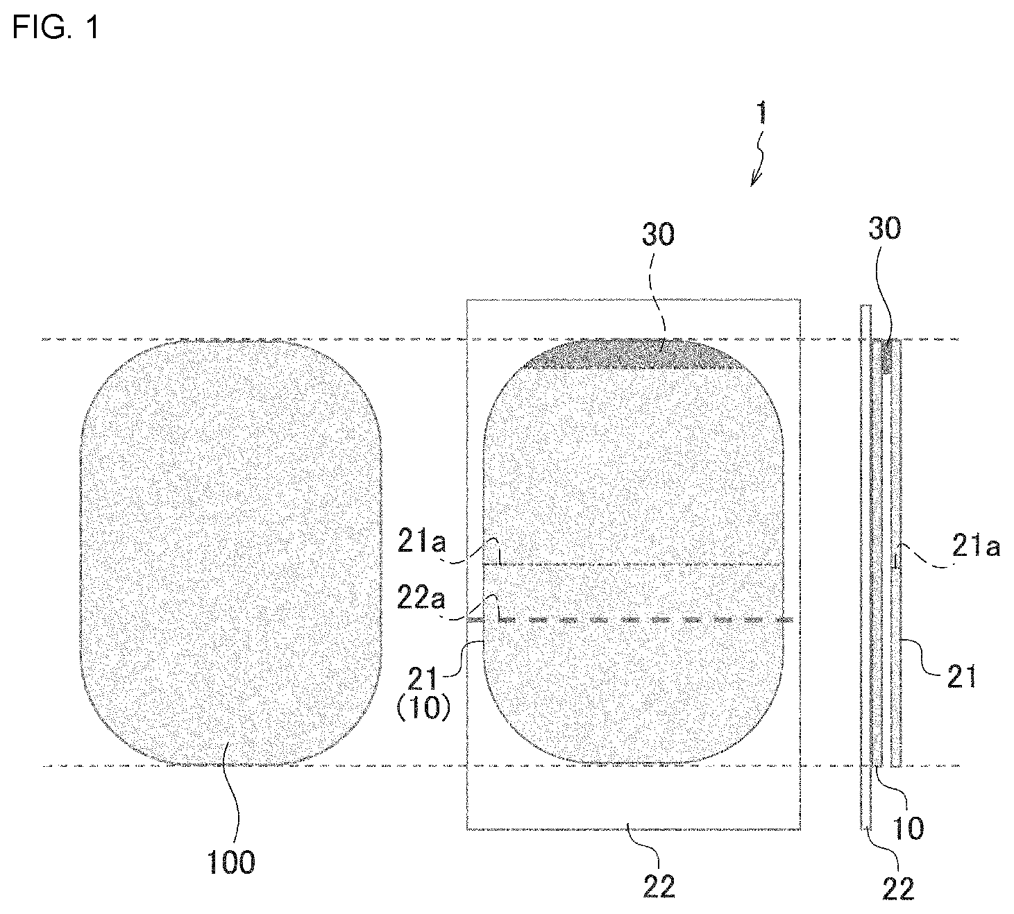
First, reference is made to to describe a configuration of a sticking component 1 according to an embodiment. illustrates, in plan and side elevation views, the sticking component 1 according to the embodiment. The following description is directed to an exemplary application of the present invention to a stick-on deep-body thermometer 100 (which corresponds to a stick-on biometric device as recited in the claims, and will be referred to simply as “deep-body thermometer 100 ” hereinafter). Accordingly, the bottom surface of the deep-body thermometer 100 is also depicted in . A suitable example of the deep-body thermometer 100 may be the deep-body thermometer described in International Publication No. 2019/225532.
The sticking component 1 includes the following major components: an adhesive component 10 having a pair of sticking surfaces (front and back surfaces) with adhesiveness; a first release component 21 removably adhered to a first sticking surface of the adhesive component 10 ; and a second release component operation button 22 removably adhered to a second sticking surface of the adhesive component 10 opposite the first sticking surface. The sticking component 1 is a laminate of the first release component 21 , the adhesive component 10 , and the second release component 22 .
To use the sticking component 1 , the first release component 21 adhered to the first sticking surface of the adhesive component 10 is removed, and the first sticking surface is adhered to the bottom surface (lower exterior body) of the deep-body thermometer 100 in a removable (peelable) manner. Further, the second release component 22 adhered to the second sticking surface of the adhesive component 10 is removed, and the second sticking surface is adhered to a living body.
The adhesive component 10 is sheet-shaped, and has a pair of sticking surfaces with adhesiveness. In use, a first of the pair of sticking surfaces of the adhesive component 10 is removably adhered to the bottom surface of the deep-body thermometer 100 . According to the embodiment, the adhesive component 10 has a substantially rectangular shape with four rounded corners, that is, the same shape as that of the bottom surface of the deep-body thermometer 100 . The adhesive component 10 is identical in dimensions (size) to the bottom surface of the deep-body thermometer 100 .
To ensure that the sticking component 1 (adhesive component 10 ) does not rip (tear) easily when removed from the bottom surface of the sticking component 1 after use of the deep-body thermometer 100 , the adhesive component 10 is preferably in the form of, for example, a doubled-sided tape including the following components: a core made of a resin film; and an adhesive layer disposed on each surface of the core. Suitable examples of the adhesive component 10 (adhesive layer) may include acrylic-based adhesives and silicone-based adhesives. Other suitable examples may include synthetic rubber-based adhesives. The adhesive component 10 has a thickness of preferably 0.005 mm to 1.0 mm, more preferably 0.05 mm to 0.3 mm.
In this case, the adhesive component 10 includes the core made of a resin film as described above. This helps to prevent the adhesive component 10 from ripping and remaining on the deep-body thermometer 100 as the adhesive component 10 is removed from the bottom surface of the deep-body thermometer 100 after use of the deep-body thermometer 100 .
The first release component 21 is a film-shaped (or sheet-shaped) component that is adhered to the first sticking surface of the adhesive component 10 during, for example, storage to thereby protect the first sticking surface so that the sticking surface does not decrease in adhesiveness as a result of dust or other contaminants adhering to the first sticking surface. The first release component 21 is peeled off from the first sticking surface of the adhesive component 10 when the deep-body thermometer 100 is to be used (when the sticking component 1 is to be adhered to the deep-body thermometer 100 ).
Likewise, the second release component 22 is a film-shaped (or sheet-shaped) component that is adhered to the second sticking surface of the adhesive component 10 when the deep-body thermometer 100 is not in use (e.g., during storage). The second release component 22 is peeled off from the second sticking surface of the adhesive component 10 when the deep-body thermometer 100 is to be used (when the deep-body thermometer 100 is to be adhered to a living body to measure deep body temperature).
At least one of the first release component 21 or the second release component 22 has a visible outline (contour). More specifically, at least one of the first release component 21 or the second release component 22 is made of, for example, an opaque material or a colored transparent material.
At least one of the first release component 21 or the second release component 22 has an outline (contour) that is capable of, when the sticking component 1 is to be adhered to the bottom surface of the deep-body thermometer 100 , at least partially overlapping (being made to coincide with) the outline (contour) of the bottom surface of the deep-body thermometer 100 in plan view. More specifically, at least one of the first release component 21 or the second release component 22 has an outline (contour) that is capable of overlapping the outline (contour) of the bottom surface of the deep-body thermometer 100 , for example, in the respective straight sections of at least two intersecting sides of the bottom surface (or at three points).
According to the embodiment, the first release component 21 has an outline (contour) that is visible (opaque), and that is capable of, when the sticking component 1 is to be adhered to the deep-body thermometer 100 , overlapping the outline (contour) of the bottom surface of the deep-body thermometer 100 in plan view (as viewed in the direction of thickness). That is, the first release component 21 is identical in shape and dimensions (size) to the bottom surface of the deep-body thermometer 100 . The second release component 22 is made of a colorless transparent material.
More specifically, the first release component 21 (paper separator) is made of, for example, opaque paper. According to the embodiment, the first release component 21 has a substantially rectangular shape with four rounded corners. Further, the outline (contour) of the first release component 21 has the same size as (coincides with) the outline (contour) of the bottom surface of the deep-body thermometer 100 . This allows the user to easily stick the sticking component 1 without misalignment by aligning the bottom surface of the deep-body thermometer 100 and the outline (contour) of the first release component 21 through visual inspection. At this time, the alignment can be performed through visual inspection because the second release component 22 described later is made of transparent PET.
In another example, only the outline (contour) of the first release component 21 may be opaque. In still another example, only a portion of the outline (contour) that overlaps (coincides with) the outline of the deep-body thermometer 100 may be opaque.
The first release component 21 is preferably divided into multiple (two in ) portions by a cut 21 a extending substantially parallel to the short sides of the first release component 21 . This configuration allows the user to easily stick the sticking component 1 to the bottom surface of the deep-body thermometer 100 without misalignment in a manner as described below. First, through visual inspection, the user aligns the first release component 21 with the bottom surface of the deep-body thermometer 100 (i.e., aligns the outline (contour) of the first release component 21 with the outline (contour) of the bottom surface of the deep-body thermometer 100 ). Then, for example, the user holds fingers against the upper halves of both the sticking component 1 and the bottom surface of the deep-body thermometer 100 to ensure that the sticking component 1 and the deep-body thermometer 100 do not become misaligned. In this state, the user removes the lower half of the first release component 21 , and sticks the lower half of the sticking component 1 to the bottom surface of the deep-body thermometer 100 . Subsequently, the user holds fingers against the lower halves of both the sticking component 1 and the bottom surface of the deep-body thermometer 100 . The user then removes the upper half of the first release component 21 , and sticks the upper half of the sticking component 1 to the bottom surface of the deep-body thermometer 100 . That is, the user sticks the sticking component 1 to the bottom surface of the deep-body thermometer 100 by removing the first release component 21 , which is divided into two portions, half by half.
The second release component 22 (PET separator) is made of, for example, colorless transparent polyethylene terephthalate (PET). More specifically, suitable examples of the second release component 22 include a PET film to which release treatment has been applied. It is to be noted, however, that the second release component 22 may be made of any hard resin, such as biaxially-oriented polypropylene (BOPP) or polyimide (PI). The second release component 22 has a thickness of preferably 0.025 mm to 0.3 mm, more preferably 0.05 mm to 0.2 mm.
According to the embodiment, the second release component 22 has a rectangular shape. In plan view, the second release component 22 preferably has an outline (contour) that is at least partially larger than the outline of the adhesive component 10 (the bottom surface of the deep-body thermometer 100 ). This allows the user to easily remove the second release component 22 by grasping a portion of the second release component 22 that extends beyond (i.e., protrudes beyond) the outline of the adhesive component 10 (the bottom surface of the deep-body thermometer 100 ), with no separate tab or other such structure required.
In particular, according to the embodiment (the example illustrated in ), the second release component 22 has an outline that, across its entire perimeter, is (generally) larger than the outline of the adhesive component 10 (the bottom surface of the deep-body thermometer 100 ). This allows the user to remove the second release component 22 by grasping anywhere on the outer edge of the second release component 22 that protrudes beyond the adhesive component 10 , irrespective of the direction of grasping or the direction of removal. Another conceivable situation where the above configuration may be useful is when multiple sticking components 1 are stacked. In this case, the adhesive component 10 may protrude out beyond the first release component 21 from the sides of one sticking component 1 , which may cause vertically adjacent sticking components 1 to adhere. Even if this occurs, the second release component 22 is larger than the adhesive component 10 as described above, and thus the user can grasp the second release component 22 to easily separate the sticking components 1 that are adhering to each other.
The second release component 22 is preferably divided into multiple (two in ) portions by a perforation, a half-cut, or a fold 22 a (to be referred to as “perforation or other separation line 22 a ” hereinafter). In this case, with the second release component 22 removed up to the perforation or other separation line 22 a , the user first aligns the deep-body thermometer 100 with a target object (living body), and sticks the deep-body thermometer 100 to the target object in this state. Subsequently, the user removes the entire second release component 22 , and sticks the entire deep-body thermometer 100 to the target object. In this way, the user is able to stick the deep-body thermometer 100 without misalignment.
The location of the perforation or other separation line 22 a may preferably be determined so that, with the second release component 22 removed up to the perforation or other separation line 22 a , the adhesive component 10 has such an exposed area that allows the deep-body thermometer 100 to be fixed to the target object (living body) while still allowing for re-sticking. If positioning the perforation or other separation line 22 a in a middle portion of the second release component 22 allows the above-mentioned condition to be met, then it is desired to position the perforation or other separation line 22 a in the middle portion. Such positioning is desired for the ability to easily remove the second release component 22 in whichever desired direction. It is to be noted, however, that if positioning the perforation or other separation line 22 a in the middle portion of the second release component 22 results in an adhesion that is too strong to allow re-sticking, then the location of the perforation or other separation line 22 a is preferably changed in accordance with desired requirements or other factors. In that case, it is preferred to make removal easier in one direction than in another, or provide multiple perforations or other separation lines 22 a . That is, it is preferred to provide multiple perforations or other separation lines 22 a so that the second release component 22 may be removed in whichever of upward and downward directions.
Further, it is preferred that a non-adhesive, film-shaped release strip 30 be partially sandwiched between one sticking surface of the adhesive component 10 and the first release component 21 . The release strip 30 is disposed on, for example, an end portion of the adhesive component 10 (first release component 21 ). Suitable exemplary materials for the release strip 30 include PET and hard resin (such as BOPP or PI). The release strip 30 has a thickness of preferably 0.005 mm to 0.3 mm, more preferably 0.05 mm to 0.2 mm. This ensures that the adhesion decreases locally in the area where the non-adhesive release strip 30 is disposed in a sandwiched fashion. As a result, after use of the deep-body thermometer 100 , the adhesive component 10 can be easily removed from the bottom surface of the deep-body thermometer 100 .
Preferably, to increase visibility, the release strip 30 is colored and transparent (color-tinted) or is opaque. In this case, the release strip 30 is colored (or opaque), which allows for easy visibility of the release strip 30 when the user removes the adhesive component 10 from the deep-body thermometer 100 after use. This facilitates removal of the adhesive component 10 .
Due to the configuration mentioned above, when the deep-body thermometer 100 is to be used (when the sticking component 1 is to be adhered to the deep-body thermometer 100 ), the first release component 21 adhered to the adhesive component 10 is removed, and then the sticking component 1 (adhesive component 10 ) is adhered to the bottom surface of the deep-body thermometer 100 .
More specifically, first, through visual inspection, the user aligns the sticking component 1 (first release component 21 ) with the bottom surface of the deep-body thermometer 100 (i.e., aligns the outline (contour) of the first release component 21 with the outline (contour) of the bottom surface of the deep-body thermometer 100 ). Then, while holding the upper halves of both the sticking component 1 and the bottom surface of the deep-body thermometer 100 with fingers of one hand (e.g., the thumb and the index finger of the left hand) to prevent misalignment between the deep-body thermometer 100 and the sticking component 1 , the user grasps a lower portion of the first release component 21 with fingers of the other hand (e.g., the thumb and the index finger of the right hand), and removes the lower half of the first release component 21 divided into two portions. The user then sticks the sticking component 1 (adhesive component 10 ) with the first release component 21 removed to the bottom surface of the deep-body thermometer 100 . Subsequently, in a similar manner, while holding the lower halves of both the sticking component 1 and the bottom surface of the deep-body thermometer 100 with fingers of one hand (e.g., the thumb and the index finger of the left hand), the user grasps an upper portion of the first release component 21 with fingers of the other hand (e.g., the thumb and the index finger of the right hand), and removes the upper half of the first release component 21 divided into two portions. The user then sticks the entirety (the remainder) of the sticking component 1 (adhesive component 10 ) to the bottom surface of the deep-body thermometer 100 .
Subsequently, when sticking the deep-body thermometer 100 to a living body to measure deep body temperature, the user grasps the outer edge of the second release component 22 with fingers, and peels off the second release component 22 adhered to the other sticking surface of the sticking component 1 (adhesive component 10 ). The user then sticks the deep-body thermometer 100 to the body surface (skin) of the user (subject). More specifically, as described above, with the second release component 22 removed up to the perforation or other separation line 22 a , the user aligns the deep-body thermometer 100 with the target object (living body), and sticks the deep-body thermometer 100 to the target object in this state. Then, the user removes the entire second release component 22 , and sticks the entire deep-body thermometer 100 to the target object.
In this way, the sticking component 1 can be adhered to the deep-body thermometer 100 (or replaced) easily and without misalignment, and the deep-body thermometer 100 can be adhered to the user's skin.
As described above in detail, according to the embodiment, the first release component 21 has an outline (contour) that is visible (opaque), and that is capable of, when the sticking component 1 is to be adhered to the deep-body thermometer 100 , overlapping the outline (contour) of the bottom surface of the deep-body thermometer 100 in plan view. This allows the user to easily align the sticking component 1 through visual inspection, by aligning the visible outline (contour) of the first release component 21 with the bottom surface of the deep-body thermometer 100 in an overlapping relationship. This in turn makes it possible to, when the sticking component 1 is to be adhered to the deep-body thermometer 100 , facilitate alignment of the sticking position, and reduce potential misalignment of the sticking position.
First Modification
The foregoing description of the embodiment is directed to a configuration in which the release strip 30 , which is a non-adhesive film-shaped strip, is sandwiched partially between one sticking surface of the adhesive component 10 , and the first release component 21 . In an alternative configuration, instead of the release strip 30 , a portion of the first release component 21 is allowed to remain on the adhesive component 10 upon sticking of the sticking component 1 to the deep-body thermometer 100 , so that this portion of the first release component 21 serves as a non-adhesive film-shaped release strip (a remaining strip of the first release component 21 ) that is sandwiched partially between the one sticking surface of the adhesive component 10 and the bottom surface of the deep-body thermometer 100 .
Reference is now made to to describe a sticking component 1 B according to a first modification of the embodiment. illustrates, in plan and side elevation views, the sticking component 1 B according to the first modification. The sticking component 1 B differs from the sticking component 1 according to the above-mentioned embodiment in that the sticking component 1 B does not include the release strip 30 , and that the sticking component 1 B includes, instead of the first release component 21 , a first release component 21 B with a slit 21 Bb.
The first release component 21 B includes a region (release strip) that is defined by the slit 21 Bb, and that remains on one sticking surface of the adhesive component 10 upon removal of the first release component 21 B. The slit 21 Bb is a closed slit that is not in contact with the outer perimeter of the first release component 21 B. Accordingly, after the adhesive component 10 is adhered to the deep-body thermometer 100 , this release strip is sandwiched between the adhesive component 10 , and a portion of the deep-body thermometer 100 near the outer edge of the deep-body thermometer 100 .
More specifically, the slit (cut) 21 Bb preferably has a closed shape that is not in contact with the outer edge of the first release component 21 B, for example, an ellipse or a rounded rectangle. The slit 21 Bb is preferably separated from the outer edge of the first release component 21 B by, for example, 2 mm or more to prevent tearing upon removal of the first release component 21 B. Multiple (two in ) such slits 21 Bb may be provided. The sticking component 1 B is otherwise identical or similar in configuration to the sticking component 1 according to the embodiment mentioned above, and thus will not be herein described in further detail.
According to the first modification, upon removal of the first release component 21 B, a portion (release strip) of the first release component 21 B that is enclosed by the slit 21 Bb with a closed shape remains on the adhesive component 10 , and the release strip is sandwiched partially between one sticking surface of the adhesive component 10 and the bottom surface of the deep-body thermometer 100 . The area where the release strip is sandwiched between these surfaces thus has locally reduced adhesion, which allows for easy removal of the sticking component 1 B after use of the deep-body thermometer 100 .
Second Modification
Reference is now made to to describe a sticking component 1 C according to a second modification of the embodiment. illustrates, in plan and side elevation views, the sticking component 1 C according to the second modification.
The sticking component 1 C differs from the sticking component 1 according to the embodiment mentioned above in the following respects: the sticking component 1 C includes a first release component 21 C instead of the first release component 21 : the sticking component 1 C includes a second release component 22 C instead of the second release component 22 ; and the sticking component 1 C includes an adhesive component 10 C instead of the adhesive component 10 .
The first release component 21 C differs from the first release component 21 in that the first release component 21 C has a rectangular shape. In this case, the first release component 21 C preferably has an outline (contour) that overlaps the respective straight sections of at least two intersecting sides of the bottom surface of the deep-body thermometer 100 . According to the second modification, the first release component 21 C has an outline (contour) that overlaps the respective straight sections of four sides of the bottom surface of the deep-body thermometer 100 (as indicated by alternate long and short dashed lines in ).
The second release component 22 C differs from the second release component 22 in that the second release component 22 C is smaller in dimensions (size) than the second release component 22 . According to the second modification, the second release component 22 C is identical in shape and dimensions (size) to the first release component 21 C. In this case, it is preferred that at least a portion of the outline (contour) of the second release component 22 C be larger than (i.e., protrude beyond) the outline of the adhesive component 10 C (the bottom surface of the deep-body thermometer 100 ). According to the second modification, the corner sections (four corners) of the second release component 22 C protrude beyond the adhesive component 10 C (the bottom surface of the deep-body thermometer 100 ). This allows the user to easily remove the second release component 22 C by grasping a portion of the second release component 22 C that protrudes beyond the adhesive component 10 C (the bottom surface of the deep-body thermometer 100 ), with no separate tab or other such structure required.
The adhesive component 10 C differs from the adhesive component 10 described above in that the adhesive component 10 C is smaller in dimensions (size) than the adhesive component 10 . That is, the outline of the adhesive component 10 C has dimensions smaller than those of the outline (contour) of the bottom surface of the deep-body thermometer 100 . Alternatively, the adhesive component 10 C may have the same dimensions as those of the outline of the bottom surface of the deep-body thermometer 100 . In that case, the first release component 21 C may likewise have the same outline (dimensions) as that of the adhesive component 10 C (the bottom surface of the deep-body thermometer 100 ). The sticking component 1 C is otherwise identical or similar in configuration to the sticking component 1 according to the embodiment mentioned above, and thus will not be herein described in further detail.
According to the second modification as well, the user is able to stick the sticking component 1 C to the bottom surface of the deep-body thermometer 100 easily and without misalignment by pressing, against the user's fingers for positioning, (at least two) (four according to the second modification) areas where the bottom surface of the deep-body thermometer 100 and the outline (contour) of the first release component 21 C overlap.
Third Modification
According to the second modification mentioned above, the first release component 21 C is opaque, and the second release component 22 C is transparent. Alternatively, the first release component 21 may be transparent, and the second release component 22 C may be opaque. Reference is now made to to describe a sticking component 1 D according to a third modification of the embodiment. illustrates, in plan and side elevation views, the sticking component 1 D according to the third modification.
The sticking component 1 D differs from the sticking component 1 C according to the second modification mentioned above in that the sticking component 1 D includes a transparent first release component 21 D instead of the opaque first release component 21 , and that the sticking component 1 D includes an opaque second release component 22 D instead of the transparent second release component 22 C.
The first release component 21 D is preferably made of, for example, colorless transparent PET. By contrast, the second release component 22 D is preferably made of, for example, opaque paper. According to the third modification, the first release component 21 D and the second release component 22 D are identical to each other in shape and dimensions (size).
In this case, the second release component 22 D preferably has an outline (contour) that overlaps the respective straight sections of at least two intersecting sides of the bottom surface of the deep-body thermometer 100 . According to the third modification, the second release component 22 D has an outline (contour) that overlaps the respective straight sections of four sides of the bottom surface of the deep-body thermometer 100 (as indicated by alternate long and short dashed lines in ). The sticking component 1 D is otherwise identical or similar in configuration to the sticking component 1 C according to the second modification mentioned above, and thus will not be herein described in further detail.
According to the third modification, the user is able to stick the sticking component 1 D to the bottom surface of the deep-body thermometer 100 easily and without misalignment by pressing, against the user's fingers for positioning, (at least two) (four according to the third modification) areas where the bottom surface of the deep-body thermometer 100 and the outline (contour) of the second release component 22 D overlap.
Fourth Modification
According to the second modification mentioned above, the first release component 21 C is opaque, and the second release component 22 C is transparent. Alternatively, the first release component 21 may be opaque, and the second release component 22 C may be also opaque. Reference is now made to to describe a sticking component 1 E according to a fourth modification of the embodiment. illustrates, in plan and side elevation views, the sticking component 1 E according to the fourth modification.
The sticking component 1 E differs from the sticking component 1 C according to the second modification mentioned above in that the sticking component 1 E includes a first release component 21 E instead of the first release component 21 C, and that the sticking component 1 E includes an opaque second release component 22 E instead of the second release component 22 C.
The first release component 21 E is preferably made of, for example, opaque paper. The first release component 21 E differs from the first release component 21 C mentioned above in that the first release component 21 E is smaller in dimensions (size) than the first release component 21 C. According to the fourth modification, the first release component 21 E is identical in shape and dimensions (size) to the adhesive component 10 C.
The second release component 22 E is likewise made of, for example, opaque paper. In this case as well, the second release component 22 E preferably has an outline (contour) that overlaps the respective straight sections of at least two intersecting sides of the bottom surface of the deep-body thermometer 100 . According to the fourth modification, the second release component 22 E has an outline (contour) that overlaps the respective straight sections of four sides of the bottom surface of the deep-body thermometer 100 (as indicated by alternate long and short dashed lines in ). The sticking component 1 E is otherwise identical or similar in configuration to the sticking component 1 C according to the second modification mentioned above, and thus will not be herein described in further detail.
According to the second modification as well, the user is able to stick the sticking component 1 E to the bottom surface of the deep-body thermometer 100 easily and without misalignment by pressing, against the user's fingers for positioning, (at least two) (four according to the fourth modification) areas where the bottom surface of the deep-body thermometer 100 and the outline (contour) of the second release component 22 E overlap.
Although an embodiment of the present invention has been described above, it is to be understood that the present invention is not limited to the embodiment described above but may accommodate various modifications. For example, although the foregoing description of the embodiment is directed to an exemplary application of the present invention to the deep-body thermometer 100 , the present invention may be applicable to thermometers other than such a deep-body thermometer. Further, the present invention may be applicable to, for example, electrocardiogramd stick-on biometric devices used to measure breathing, pulse, or other vital signs.
The size, positioning, number, and other specific details of the above-mentioned components and features, such as the first release component 21 , the second release component 22 , the adhesive component 10 , the slit 21 Bb, the cut 21 a , and the perforation or other separation line 22 a , are not limited to those exemplified in the above embodiment but may be determined as appropriate based on desired requirements or other factors.
REFERENCE SIGNS LIST
•
• 1 , 1 B, 1 C, 1 D, 1 E sticking component • 10 , 10 C adhesive component • 21 , 21 B, 21 C, 21 D, 21 E first release component • 22 , 22 C, 22 D, 22 E second release component • 21 a , 21 Ba, 21 Ca, 21 Da, 21 Ea cut • 21 Bb slit • 22 a perforation, half-cut, or fold • 30 release strip • 100 deep-body thermometer (stick-on biometric device)
Figures (5)
Citations
This patent cites (15)
- US9580626
- US2011/0152738
- US2017/0136648
- US2018/0243141
- US2019/0046033
- US2019/0261923
- US2020/0309608
- USH1178389
- US2000160111
- US2013501591
- US2017529114
- US2018509191
- US2019537470
- US2020078440
- US2019131203