Impregnation Device for Fiber Prepreg and Method Thereof
Abstract
The present disclosure provides an impregnation device for a fiber prepreg, which includes a film layer separation assembly, a hot pressing element, and a thermal barrier element. The hot pressing element is disposed beneath the film layer separation assembly. The thermal barrier element is disposed between the film layer separation assembly and the hot pressing element. The present disclosure also provides an impregnation method for a fiber prepreg.
Claims (5)
1. An impregnation device for a fiber prepreg, comprising: a film layer separator, comprising: a first roller; a film layer receiver disposed over the first roller; and a second roller disposed between the film layer receiver and the first roller in a vertical direction, and a separation angle between a direction of the first roller facing the film layer receiver and a direction of the first roller facing the second roller being greater than 0°; a resin film provider disposed over the first roller, and when projected vertically on a horizontal plane where the first roller is located, the resin film provider and the film layer receiver being respectively located at opposite sides of the first roller, wherein the horizontal plane where the first roller is located is perpendicular to the vertical direction; a fiber provider disposed beneath the film layer separator; a hot pressing processor disposed beneath the film layer separator in the vertical direction; and a thermal barrier disposed between the film layer separator and the hot pressing processor in the vertical direction, wherein the thermal barrier comprises an insulating material and is arc-shaped, and a concave shape of the thermal barrier only faces the hot pressing processor to converge heat at a side of the hot pressing processor.
Show 4 dependent claims
2. The impregnation device of claim 1 , wherein a position of the second roller is adjustable, and a separation angle is able to be changed by changing the position of the second roller.
3. The impregnation device of claim 1 , wherein the insulating material comprises a porous material, a heat reflective material, or a combination thereof.
4. The impregnation device of claim 1 , wherein a surface of the thermal barrier close to the hot pressing processor is made of a heat reflective material.
5. The impregnation device of claim 1 , wherein when projected vertically on a horizontal plane where the hot pressing processor is located, a projection of the thermal barrier is coincident and larger than a projection of the hot pressing processor, wherein the horizontal plane where the hot pressing processor is located is perpendicular to the vertical direction.
Full Description
Show full text →
CROSS-REFERENCE TO RELATED APPLICATION
This application claims priority to Taiwan Application Serial Number 110132416, filed Sep. 1, 2021, which is herein incorporated by reference.
BACKGROUND
Field of Invention
The present disclosure relates to an impregnation device for a fiber prepreg and an impregnation method thereof.
Description of Related Art
Fabrication of a fiber prepreg has two stages. First, a resin coating stage is performed, that is, a resin is coated on a release layer. Next, an impregnation stage is performed, mainly by hot pressing a resin layer and a fiber layer (yarn spread treatment can be performed before hot pressing) to form the fiber prepreg. Fabrics made from the fiber prepreg are widely used in a wide range of applications. For example, a reinforced composite material made from a carbon fiber prepreg composed of carbon fibers and a resin is lightweight and has excellent strength and modulus, so that it is widely used in structural parts of sports and entertainment products, structures and interior parts of transportation vehicles, or civil construction.
However, in a conventional impregnation device, in order to facilitate continuous execution of operations, a resin layer sending element and a separation element for separating a resin layer and a film layer are adjacent to a hot pressing element (e.g., disposed over the hot pressing element). When the hot pressing element is heated, generated heat radiation and hot air will cause the resin layer located on the sending element and the separation element to soften too early, so that when the film layer is subsequently separated, the resin sticks to the film layer, resulting in poor impregnation.
SUMMARY
Therefore, an aspect of the present disclosure provides an impregnation device for a fiber prepreg, which includes a film layer separation assembly, a hot pressing element disposed beneath the film layer separation assembly in a vertical direction, and a thermal barrier element disposed between the film layer separation assembly and the hot pressing element in the vertical direction.
In some embodiments, the film layer separation assembly includes: a first roller; a film layer receiving element disposed over the first roller; and a second roller disposed between the film layer receiving element and the first roller in the vertical direction, and a separation angle between a direction of the first roller facing the film layer receiving element and a direction of the first roller facing the second roller is greater than 0°.
In some embodiments, a position of the second roller is adjustable, and a separation angle is able to be changed by changing the position of the second roller.
In some embodiments, the impregnation device further includes: a resin film sending element disposed over the first roller, and when projected vertically on a horizontal plane where the first roller is located, the resin film sending element and the film layer receiving element are respectively located at opposite sides of the first roller, in which the horizontal plane where the first roller is located is perpendicular to the vertical direction; and a fiber sending element disposed beneath the film layer separation assembly.
In some embodiments, a surface of the thermal barrier element close to the hot pressing element is made of a heat reflective material.
In some embodiments, the thermal barrier element is arc-shaped.
In some embodiments, when projected vertically on a horizontal plane where the hot pressing element is located, a projection of the thermal barrier element is coincident and larger than a projection of the hot pressing element, in which the horizontal plane where the hot pressing element is located is perpendicular to the vertical direction.
An aspect of the present disclosure provides an impregnation method for a fiber prepreg, which includes: providing an impregnation device including a film layer separation assembly, a hot pressing element disposed beneath the film layer separation assembly in a vertical direction, and a thermal barrier element disposed between the film layer separation assembly and the hot pressing element in the vertical direction; providing a resin film, in which the resin film includes a release film, a resin layer located on the release film, and a film layer located on the resin layer; separating the film layer and the resin layer of the resin film using the film layer separation assembly of the impregnation device to obtain a resin composite structure including the release film and the resin layer; providing a fiber layer; hot pressing the resin composite structure, the fiber layer and the resin composite structure from top to bottom using the hot pressing element of the impregnation device at a temperature higher than 90° C. to obtain a fiber prepreg, in which the resin layer of the fiber prepreg is in direct contact with the fiber layer.
In some embodiments, during using the hot pressing element of the impregnation device, the film layer separation assembly of the impregnation device is used simultaneously to separate the film layer and the resin layer of the resin film.
In some embodiments, separating the film layer and the resin layer of the resin film using the film layer separation assembly of the impregnation device includes: when a tack of the resin layer is in a range of from 500 grams to 2,000 grams, a separation angle of the film layer and the resin layer in the film layer separation assembly is adjusted to be in a range of from 18° to 45°.
BRIEF DESCRIPTION OF THE DRAWINGS
In order to make the above and other objects, features, advantages and embodiments of the present disclosure more clearly understood, the detailed description of the accompanying drawings is as follows:
is a flow chart of an impregnation method for a fiber prepreg according to some embodiments of the present disclosure.
is a side view illustrating an impregnation device for a fiber prepreg when an impregnation method is performed according to some embodiments of the present disclosure.
is a side view illustrating an impregnation device for a fiber prepreg when an impregnation method is performed according to some embodiments of the present disclosure.
A- 4 D illustrate different examples of thermal barrier elements in some embodiments of the present disclosure.
DETAILED DESCRIPTION
It is to be understood that different implementations or embodiments provided in the following may implement different features of the subject matter of the present disclosure. The embodiments of specific components and arrangements are used to simplify the disclosure and not to limit the disclosure. Of course, these are only examples and are not intended to be limiting. For example, the description below that the first feature is formed on the second feature includes the two being in direct contact, or there are other additional features between the two that are not in direct contact. Furthermore, the present disclosure may repeat reference numerals and/or symbols in the various embodiments. Such repetition is for simplicity and clarity and does not represent a relationship between the various embodiments and/or configurations discussed.
Terms used in this specification generally have their ordinary meanings in the art and in the context in which they are used. The embodiments used in this specification, including examples of any terms discussed herein, are illustrative only and do not limit the scope and meaning of the disclosure or any exemplified terms. Likewise, the present disclosure is not limited to some of the implementations provided in this specification.
In addition, spatially relative terms, such as “beneath”, “over”, etc., are used to conveniently describe the relative relationship between one element or feature and another element or feature in the drawings. These spatially relative terms are intended to encompass different orientations of the device in use or operation in addition to the orientation shown in the figures. The device may be otherwise oriented (rotated 90° or at other orientations), and the spatially relative description used herein may likewise be interpreted accordingly.
In this article, unless the context of the article is specifically limited, otherwise “a” and “the” can refer to a single one or a plurality of. It will be further understood that the terms “comprising”, “including”, “having” and similar words used herein designate the recited features, regions, integers, steps, operations, elements and/or components, but do not exclude other features, regions, integers, steps, operations, elements, components, and/or groups thereof.
As used herein, “comprise”, “include”, “have”, and similar terms as used herein indicate described features, regions, integers, steps, operations, elements and/or components, but not exclude other features, regions, integers, steps, operations, elements, components and/or groups.
All documents cited herein by reference are deemed to be specifically and individually incorporated by reference for each individual document or patent application. To the extent that a citation has a definition or usage of a term that is inconsistent with or contrary to the definition of the term herein, the definition of the term herein applies.
Several embodiments are listed below to describe the touch device of the present disclosure in more detail, but it is only for illustration purposes, not for limiting the present disclosure, and the protection scope of the present invention shall be defined by the appended patent application scope whichever shall prevail.
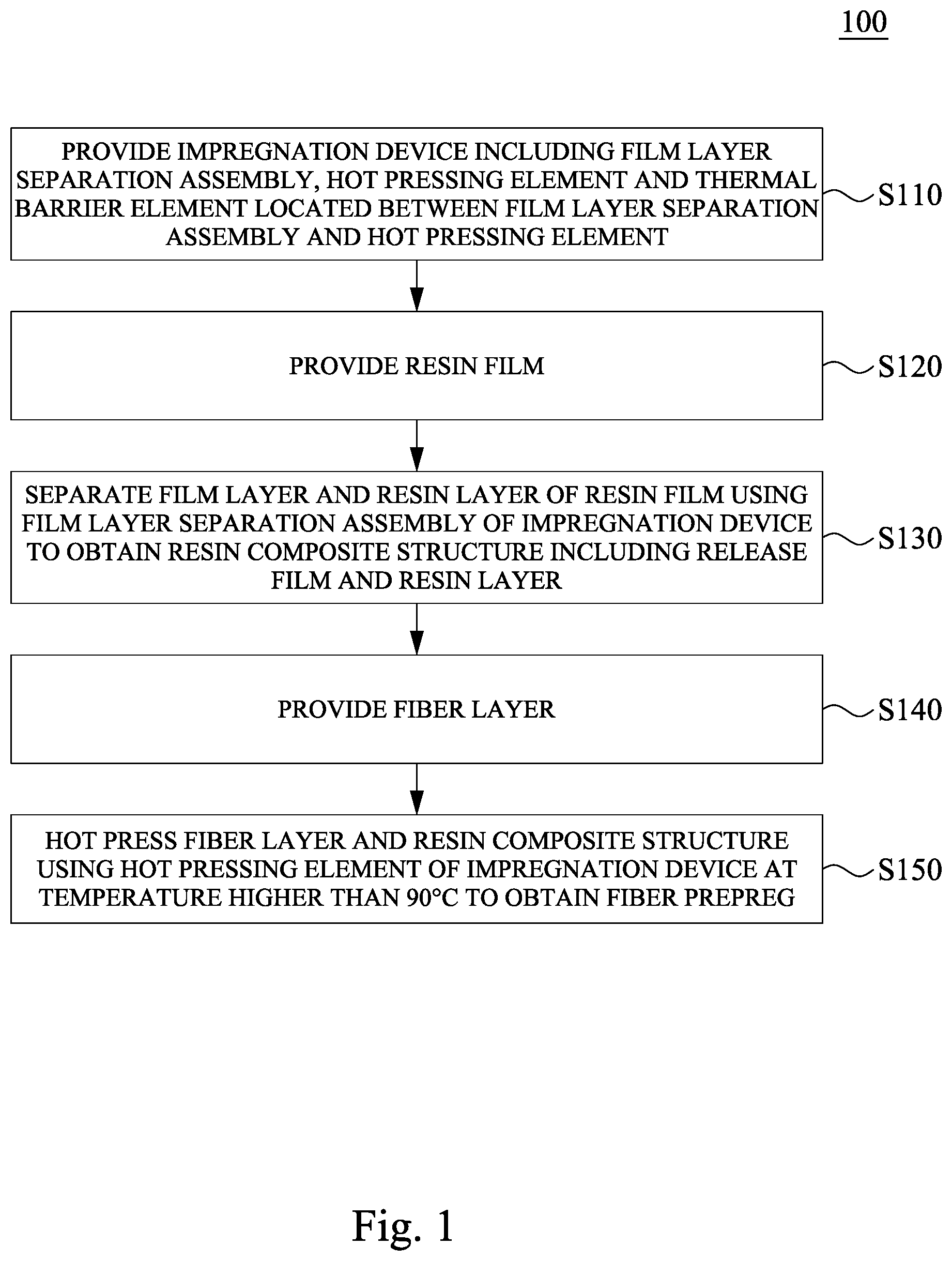
Please refer to . is a flowchart of an impregnation method 100 for a fiber prepreg according to some embodiments of the present disclosure, which includes step S 110 , providing an impregnation device including a film layer separation assembly, a hot pressing element and a thermal barrier element located between the film layer separation assembly and the hot pressing element; step S 120 , providing a resin film; step S 130 , separating a film layer and a resin layer of the resin film using the film layer separation assembly of the impregnation device to obtain a resin composite structure including a release film and the resin layer; step S 140 , providing a fiber layer; and step S 150 , hot pressing the fiber layer and the resin composite structure using the hot pressing element of the impregnation device at a temperature higher than 90° C. to obtain a fiber prepreg.
In some embodiments, the impregnation device may be used only in some steps (e.g., the steps S 130 and S 150 ). For example, the resin film and the fiber layer may be provided manually or by other machines, respectively. In some embodiments, all of the steps of the impregnation method 100 shown in may be performed by only a single impregnation device for the fiber prepreg. For easy understanding, the following takes an impregnation device 200 of as an example to specifically describe a process of the impregnation method 100 for the fiber prepreg. However, aspects of the present disclosure are not limited thereto.
is a side view illustrating an impregnation device 200 for a fiber prepreg when an impregnation method is performed according to some embodiments of the present disclosure.
As shown in , the impregnation device 200 is provided, which includes a resin film sending element 210 , a film layer separation assembly 220 , a fiber sending element 230 , a hot pressing element 240 , and a thermal barrier element 250 . Unless otherwise specified below, the relative relationship between “up” and “down” between the elements is mainly for the Z-axis direction (vertical direction). The resin film sending element 210 is adjacent to the film layer separation assembly 220 , for example, is located over a first roller 222 of the film layer separation assembly 220 . When projected vertically on a horizontal plane where the first roller 222 is located (the plane on the X axis that is perpendicular to the Z axis), the resin film sending element 210 and a film layer receiving element 224 are respectively located at opposite sides of the first roller 222 . The hot pressing element 240 is disposed beneath the film layer separation assembly 220 . The fiber sending element 230 is disposed beneath the film layer separation assembly 220 , for example, in the Z-axis direction, is disposed between rollers R 1 and R 2 of the hot pressing element 240 . The thermal barrier element 250 is disposed between the hot pressing element 240 and the film layer separation assembly 220 .
First, a resin film M 0 is provided via the resin film sending element 210 , in which the resin film M 0 includes a release film L 1 , a resin layer L 2 on the release film L 1 , and a film layer L 3 on the resin layer L 2 .
In some embodiments, the film layer L 3 is a transparent film structure for blocking the contact of the resin layer L 2 with suspended particles in the environment or contaminants from other sources, so as to keep a surface of the resin layer L 2 clean. In some embodiments, a material of the film layer L 3 may include, for example, polymer (e.g., plastic).
In some embodiments, a material of the resin layer L 2 may include a thermoplastic resin (e.g., epoxy resin). In some embodiments, a melting point of the resin layer L 2 is lower than 90° C., for example, the melting point of the resin layer L 2 is 70° C., 80° C., 90° C., or any value in the foregoing range.
Next, the resin film M 0 is transported to the film layer separation assembly 220 along a specific path using the resin film sending element 210 . The film layer separation assembly 220 is configured to separate the film layer L 3 and the resin layer L 2 of the resin film M 0 through a specific separation angle A, so as to obtain a resin composite structure M 1 , in which the resin composite structure M 1 includes the release film L 1 and the resin layer L 2 on the release film L 1 .
In some embodiments, the film layer separation assembly 220 includes the first roller 222 , the film layer receiving element 224 , and a second roller 226 . The first roller 222 is disposed beneath the resin film sending element 210 , and is configured to receive the resin film M 0 . The film layer receiving element 224 is disposed over the first roller 222 , and is configured to receive the separated film layer L 3 from the first roller 222 (e.g., wind the film layer L 3 ). The second roller 226 is disposed between the film layer receiving element 224 and the first roller 222 in the Z-axis direction, and is configured to separate the resin layer L 2 and the release film L 1 (i.e., the resin composite structure M 1 ) from the resin film M 0 through the separation angle A (greater than 0° between a direction of the first roller 222 facing the film layer receiving element 224 and a direction of the first roller 222 facing the second roller 226 .
In some embodiments, a position of the second roller 226 is adjustable, and the separation angle A is able to be changed by changing the position of the second roller 226 . For example, the second roller 226 is moved along the X-axis direction or the Z-axis direction based on a tack of the resin layer L 2 to change the separation angle A, so as to achieve a better separation effect of the film layer L 3 .
For example, please refer to . is also a side view illustrating an impregnation device 200 for a fiber prepreg when an impregnation method is performed according to some embodiments of the present disclosure. The difference of from is that the resin layer L 2 shown in has a relatively high tack. In order to facilitate the separation of the resin layer L 2 and the film layer L 3 , the position of the second roller 226 is moved downward along a direction D (the Z-axis direction) to increase the separation angle A.
In some embodiments, when the tack of the resin layer L 2 is lower than or equal to 500 grams, the separation angle between the film layer L 3 and the resin layer L 2 can be adjusted to be lower than or equal to 18°. For example, when the tack of the resin layer L 2 is from 100 grams to 500 grams, the separation angle between the film layer L 3 and the resin layer L 2 is adjusted to be from 13° to 18° (e.g., 13°, 14°, 15°, 16°, 17°, 18°, or any value in the foregoing range).
In some embodiments, if the tack of the resin layer L 2 is from 500 grams to 2,000 grams, the separation angle between the film layer L 3 and the resin layer L 2 is adjusted to be from 18° to 45°.
For example, if the tack of the resin layer L 2 is from 500 grams to 900 grams, the separation angle between the film layer L 3 and the resin layer L 2 is adjusted to be from 18° to 25° (e.g., 18°, 19°, 20°, 21°, 22°, 23°, 24°, 25°, or any value in the foregoing range). If the tack of the resin layer L 2 is from 900 grams to 1,300 grams, the separation angle between the film layer L 3 and the resin layer L 2 is adjusted to be from 25° to 33° (e.g., 25°, 26°, 27°, 28°, 29°, 30°, 31°, 32°, 33°, or any value in the foregoing range). If the tack of the resin layer L 2 is between 1,300 grams to 2,000 grams, the separation angle between the film layer L 3 and the resin layer L 2 is adjusted to be from 33° to 45° (e.g., 33°, 34°, 35°, 36°, 37°, 38°, 39°, 40°, 41°, 42°, 43°, 44°, 45°, or any value in the foregoing range). When the tack of the resin layer L 2 is greater than or equal to 2,000 grams, the separation angle between the film layer L 3 and the resin layer L 2 is 45°.
It should be noted that, in the case where the separation angle A is not adjusted according to the tack of the resin layer L 2 , if the tack of the resin layer L 2 is too high, the separation effect may be poor, and the resin of the resin layer L 2 remains on a surface of the film layer L 3 ; if the tack of the resin layer L 2 is too low, the film layer L 3 is separated from the resin film M 0 too early since a separation stress provided by the separation angle A is too large, which may cause the film layer L 3 to be displaced and difficult to be effectively received, and also increases an exposure time of the resin layer L 2 and indirectly increases the risk of contaminant molecules attaching to the surface of the resin.
Please refer back to , on the other hand, a fiber layer F is provided to the hot pressing element 240 simultaneously using the fiber sending element 230 . In some embodiments, the fiber layer F is, for example, carbon fibers or glass fibers, or the like. In some embodiments, a yarn spreading element 260 is disposed between the fiber sending element 230 and the hot pressing element 240 , and is configured to spread the fiber layer F and adjust fiber arrangement and/or width and other properties of the fiber layer F.
Next, the fiber layer F is received using the hot pressing element 240 , and two resin composite structure M 1 are received simultaneously from upper and lower sides (in terms of the Z-axis direction) of the fiber layer F (e.g., the fiber layer F is acted as a symmetrical axis, and the element at the lower side and the element at the upper side are distributed symmetrically (not shown)).
Next, the resin layers L 2 of the two resin composite structures M 1 are in direct contact with the fiber layer L at a temperature higher than 90° C. (e.g., 90° C., 100° C., 110° C., 120° C., or any value in the foregoing range), and those with an order of the resin composite structure M 1 , the fiber layer F and the resin composite structure M 1 from top to bottom are hot-pressed to obtain a fiber prepreg C, in which both an upper surface and a lower surface of the fiber layer F of the fiber prepreg C are in direct contact with the resin layer L 2 .
It is worth emphasizing that the impregnation device 200 is a continuous device. While the fiber layer F and the resin composite structures M 1 are hot-pressed using the hot pressing element 240 , the film layer L 3 and the resin layer L 2 of the resin film M 0 are separated using the film layer separation assembly 220 simultaneously. Therefore, if there is no thermal barrier element 250 disposed between the hot pressing element 240 and the film layer separation assembly 220 for blocking heat from the hot pressing element 240 , the resin may be softened by heat and stick to the film layer L 3 during separation when the film layer separation assembly 220 separates the resin film M 0 , causing the resin layer L 2 for subsequent hot pressing to be damaged, reducing an impregnation effect of the fiber prepreg C, even if the hot pressing is performed at a temperature lower than 90° C. (e.g., 70° C. to 85° C.) using the hot pressing element 240 .
In some embodiments, the thermal barrier element 250 is an insulating material, such as a porous material (e.g., foam or fibers) or a heat reflective material (aluminum foil or nickel, etc.).
In some embodiments, the thermal barrier element 250 can completely shield the hot pressing element 240 , for example, when projected vertically on a horizontal plane where the hot pressing element 240 is located (the plane on the X axis that is perpendicular to the Z axis), a projection of the thermal barrier element 250 is coincident and larger than a projection of the hot pressing element 240 . The hot pressing element 240 is shielded by a large area to prevent hot air from flowing to the film layer separation assembly 220 and the resin film sending element 210 , so as to achieve a better heat blocking effect.
In some embodiments, a surface 252 A of the thermal barrier element 250 close to the hot pressing element 240 may be made of a heat reflective material (e.g., metal (aluminum foil or nickel, etc.)), or a shape of the thermal barrier element 250 is adjusted to enhance a heat blocking effect.
For example, see A- 4 D , those illustrate different examples of the thermal barrier elements 250 in some embodiments of the present disclosure.
The thermal barrier elements 250 in A and 4 B (please refer to simultaneously) are double-layered structures. One side close to the hot pressing element 240 is a heat reflective layer 252 , and another side is a porous layer 254 . The difference between A and B is that the thermal barrier element 250 in B is arc-shaped, and a concave shape of the arc is designed with the heat reflective layer 252 facing the hot pressing element 240 to converge heat at a side of the hot pressing element 240 . Compared with a rectangular plate design in A , the arc shape in B achieves a better heat blocking effect. Even if the hot pressing temperature is raised to 110° C., the resin layer L 2 is not soften excessively to remain on the film layer L 3 .
The main difference between the thermal barrier elements 250 of C and 4 D and the thermal barrier elements 250 of A and 4 B is that the thermal barrier element 250 of C and 4 D is a porous layer 254 covered with a heat reflective layer 252 . That is, in the thermal barrier element 250 shown in C and 4 D , the heat reflective layer 252 is exposed on an outer surface, which can also achieve a heat blocking effect of reflecting thermal energy. On the other hand, the difference between C and D is that C is a rectangle, while D is an arc. This part of the discussion can be referred to the description of A and B , and will not be repeated here.
Therefore, please refer back to , by adjusting the position, shielding area, shape, material and structural design of the thermal barrier element 250 , the heat blocking effect of the thermal barrier element 250 can be regulated, so that an allowable hot pressing temperature of the hot pressing element 240 is increased when the film layer L 3 is separated and there is no resin remained on the film layer L 3 , thereby increasing selection of resin types of the resin layer L 2 . For example, a resin with a lower melting point (e.g., lower than 90° C.) can be included in the selection of the resin layer L 2 .
In some embodiments, a thickening process of the fiber layer F may be selectively added according to a requirement of a thickness of the fiber layer F, which includes providing another fiber layer; removing the release film L 1 of the fiber prepreg C to obtain a fiber prepreg to be processed; and hot pressing the other fiber layer and the fiber prepreg to be processed in a way that the other fiber layer is in direct contact with the resin layer L 2 to obtain a thickened fiber prepreg.
Some embodiments of the present disclosure provides the impregnation device for the fiber prepreg and the impregnation method thereof, which avoids premature softening of the resin film and adhesion to the film layer when the film layer is separated by the film layer separation assembly due to hot air of the hot pressing element, resulting in resin defects and poor fiber impregnation.
Although the present disclosure has been disclosed above in several specific embodiments, various modifications, changes, and substitutions may be made to the foregoing disclosure, and it should be understood that those do not depart from the spirit and scope of the present disclosure, and certain features of embodiments of the present disclosure will be employed without corresponding use of other features. Therefore, the spirit of the present disclosure and the scope of the claims should not be limited to those described in the exemplary embodiments above.
Figures (4)
Citations
This patent cites (25)
- US3755061
- US8807186
- US10737411
- US2002/0129886
- US2004/0040669
- US2011/0129737
- US2014/0070449
- US2014/0338824
- US2018/0345540
- US2019/0284731
- US2020/0376715
- US104891254
- US109849219
- US2572110
- US2012167260
- US2014055136
- US2014058136
- US2019523834
- US2019199488
- US2023-33240
- US20120093701
- US10-2018-0096347
- US592005
- USM465662
- USWO2016/178399