Retractable Tray Fixing Device and Fixing Method
Abstract
A latch operating portion, which is made of an elastically deformable constituent material, connected to a knob portion of a latch, and operated by an operator to insert and remove a claw portion provided at a latch beam portion into and from a through hole of trays, is provided, and in a case in which the knob portion is pushed toward a wall portion by a fingertip operation to elastically deform the constituent material, the latch operating portion separates the claw portion from the through hole, restores the elastically deformed constituent material to its original shape when the fingertip is released, and inserts the claw portion into the through hole.
Claims (10)
1. A retractable tray fixing device for a retractable tray that includes a first tray and a second tray that is slidable relative to the first tray, the retractable tray fixing device comprising: a latch including a beam portion provided along a bottom surface of the second tray and a knob portion provided integrally with the beam portion along a wall portion forming an edge of the second tray; a claw portion provided at a tip position of the beam portion of the latch and inserted into and removed from a through hole penetrating both of the first tray and the second tray; and a latch operating portion that is made of an elastically deformable constituent material, connected to the knob portion of the latch, and operated by an operator's fingertip operation to insert and remove the claw portion into and from the through hole, wherein, in a case in which the knob portion of the latch is pushed toward the wall portion by the operator's fingertip operation to elastically deform the constituent material, the latch operating portion separates the claw portion of the latch from the through hole, and in a case in which the operator performs an operation of removing the fingertip, the latch operating portion restores the elastically deformed constituent material to an original shape of the constituent material and inserts the claw portion into the through hole.
10. A fixing method for a retractable tray that includes a first tray and a second tray that is slidable relative to the first tray, the method comprising: providing a latch including a beam portion provided along a bottom surface of the second tray and a knob portion provided along a wall portion forming an edge of the second tray; providing a claw portion at a tip position of the beam portion of the latch to be inserted into and removed from a through hole penetrating both of the first tray and the second tray; and providing a latch operating portion that is made of an elastically deformable constituent material, connected to the knob portion of the latch, and operated by an operator's fingertip operation to insert and remove the claw portion into and from the through hole, wherein, in a case in which the knob portion of the latch is pushed toward the wall portion by the operator's fingertip operation to elastically deform the constituent material, the latch operating portion separates the claw portion from the through hole, and in a case in which the operator performs an operation of removing the fingertip, the latch operating portion restores the elastically deformed constituent material to an original shape of the constituent material and inserts the claw portion into the through hole.
Show 8 dependent claims
2. The retractable tray fixing device according to claim 1 , wherein the latch is supported such that the beam portion is swingable vertically around a horizontal axis located on the bottom surface of the second tray.
3. The retractable tray fixing device according to claim 1 , wherein the latch includes the beam portion formed to be long and the knob portion formed to be short, and forms an L-shape as a whole.
4. The retractable tray fixing device according to claim 1 , wherein the latch operating portion is integral with the latch.
5. The retractable tray fixing device according to claim 1 , wherein the latch operating portion is formed as an individual body from the latch.
6. The retractable tray fixing device according to claim 1 , wherein the through hole includes a single common tray hole formed in the second tray and a plurality of individual tray holes formed at intervals in the first tray, and axes of the common tray hole and one of the individual tray holes are aligned with each other to form the through hole.
7. The retractable tray fixing device according to claim 1 , wherein the latch operating portion is formed in an L-shape to conform to a shape of the latch and has a fixed portion provided along the beam portion of the latch and a standing portion provided along the knob portion of the latch, and an elastically deformable bent portion is provided at a tip of the standing portion, and the knob portion of the latch is connected to an inner side of the bent portion.
8. The retractable tray fixing device according to claim 7 , wherein the latch operating portion is configured such that the fixed portion disposed along the beam portion of the latch is fixed on the bottom surface of the second tray.
9. The retractable tray fixing device according to claim 1 , wherein the first tray and the second tray are provided with guide rails formed in sliding directions and guide pins that move along the guide rails.
Full Description
Show full text →
This application is based upon and claims the benefit of priority from Japanese Patent Application No. 2022-003638, filed Jan. 13, 2022, the disclosure of which is incorporated herein in its entirety by reference.
TECHNICAL FIELD
The present disclosure relates to a retractable tray fixing device and a fixing method in which lengths of two trays can be adjusted depending on intended uses.
BACKGROUND ART
In paper feeding devices used in printers, copiers, scanners, and other devices for supplying paper, which perform processing such as printing and reading on cut paper, a so-called retractable tray including a mechanism that can freely contract or expand a paper storage space of the tray in accordance with the size of the paper may be used. Such a retractable tray has a fixing device that fixes the tray in its contracted or extended state.
For example, a paper feeding cassette disclosed in Japanese Unexamined Patent Application, First Publication No. H06-144598 (hereinafter Patent Document 1) has a configuration in which a cassette main body in which a sliding cassette, which is provided separately from a cassette body, is superimposed and slidably disposed on the cassette body in which cut paper is stored.
In addition, in the paper feeding cassette, a fixing portion is provided between the cassette body and the sliding cassette.
The fixing portion is provided with a plurality of recessed portions disposed at intervals in a sliding direction on a surface facing the cassette body and the sliding cassette, and a protruding portion selectively fitted into one of the recessed portions, and thus the size of a paper storage space in the cassette body can be adjusted in accordance with the size of the cut paper.
SUMMARY
Incidentally, in the paper feeding cassette disclosed Patent Document 1, when a fitting position of the recessed portions and the protruding portion in the fixing portion is adjusted, it is required to separate the sliding cassette from the cassette body in a vertical direction, which requires a space for position adjustment.
However, since the above-described paper feeding cassette may need to be installed in a limited narrow space, an installation place for a device may be restricted in order to secure a work space for performing fixation or release of the sliding cassette relative to the cassette body or due to considerations for securing the work space.
Further, as a fixing portion, there is a related configuration using a stopper and a positioning hole disclosed in Japanese Unexamined Utility Model Application, First Publication No. H04-132766 (hereinafter Patent Document 2). Also, for adjustment of a paper storage space, a related configuration using a length size restriction mechanism disclosed in Japanese Unexamined Utility Model Application, First Publication No. H02-103032 (hereinafter Patent Document 3) is disclosed.
However, in the paper feeding cassette disclosed in Patent Document 1, even if the related configurations of Patent Documents 2 and 3 are combined therewith, an operation of fixing or releasing of the sliding cassette to the cassette body cannot be easily performed, and improvement has been anticipated in this regard.
The present disclosure has been made in order to solve any of the above problems, and an example object of the present disclosure is to provide a retractable tray fixing device and a fixing method enabling space saving.
A retractable tray fixing device according to a first example aspect of the present disclosure, for a retractable tray that includes a first tray and a second tray that is slidable relative the first tray, includes: a latch including a beam portion provided along a bottom surface of the second tray and a knob portion provided integrally with the beam portion along a wall portion forming an edge of the second tray; a claw portion provided at a tip position of the beam portion of the latch and inserted into and removed from a through hole penetrating both of the first tray and the second tray; and a latch operating portion that is made of an elastically deformable constituent material, connected to the knob portion of the latch, and operated by an operator's fingertip operation to insert and remove the claw portion into and from the through hole, wherein, in a case in which the knob portion of the latch is pushed toward the wall portion by the operator's fingertip operation to elastically deform the constituent material, the latch operating portion separates the claw portion from the through hole, and in a case in which the operator performs an operation of removing the fingertip, the latch operating portion restores the elastically deformed constituent material to an original shape of the constituent material and inserts the claw portion into the through hole.
A fixing method according to a second example aspect of the present disclosure, for a retractable tray that includes a first tray and a second tray that is slidable relative to the first tray, includes: providing a latch including a beam portion provided along a bottom surface of the second tray and a knob portion provided along a wall portion forming an edge of the second tray; providing a claw portion at a tip position of the beam portion of the latch to be inserted into and removed from a through hole penetrating both of the first tray and the second tray; and providing a latch operating portion that is made of an elastically deformable constituent material, connected to the knob portion of the latch, and operated by an operator's fingertip operation to insert and remove the claw portion into and from the through hole, wherein, in a case in which the knob portion of the latch is pushed toward the wall portion by the operator's fingertip operation to elastically deform the constituent material, the latch operating portion separates the claw portion from the through hole, and in a case in which the operator performs an operation of removing the fingertip, the latch operating portion restores the elastically deformed constituent material to an original shape of the constituent material and inserts the claw portion into the through hole.
In the present disclosure, it is possible to achieve space saving.
BRIEF DESCRIPTION OF THE DRAWINGS
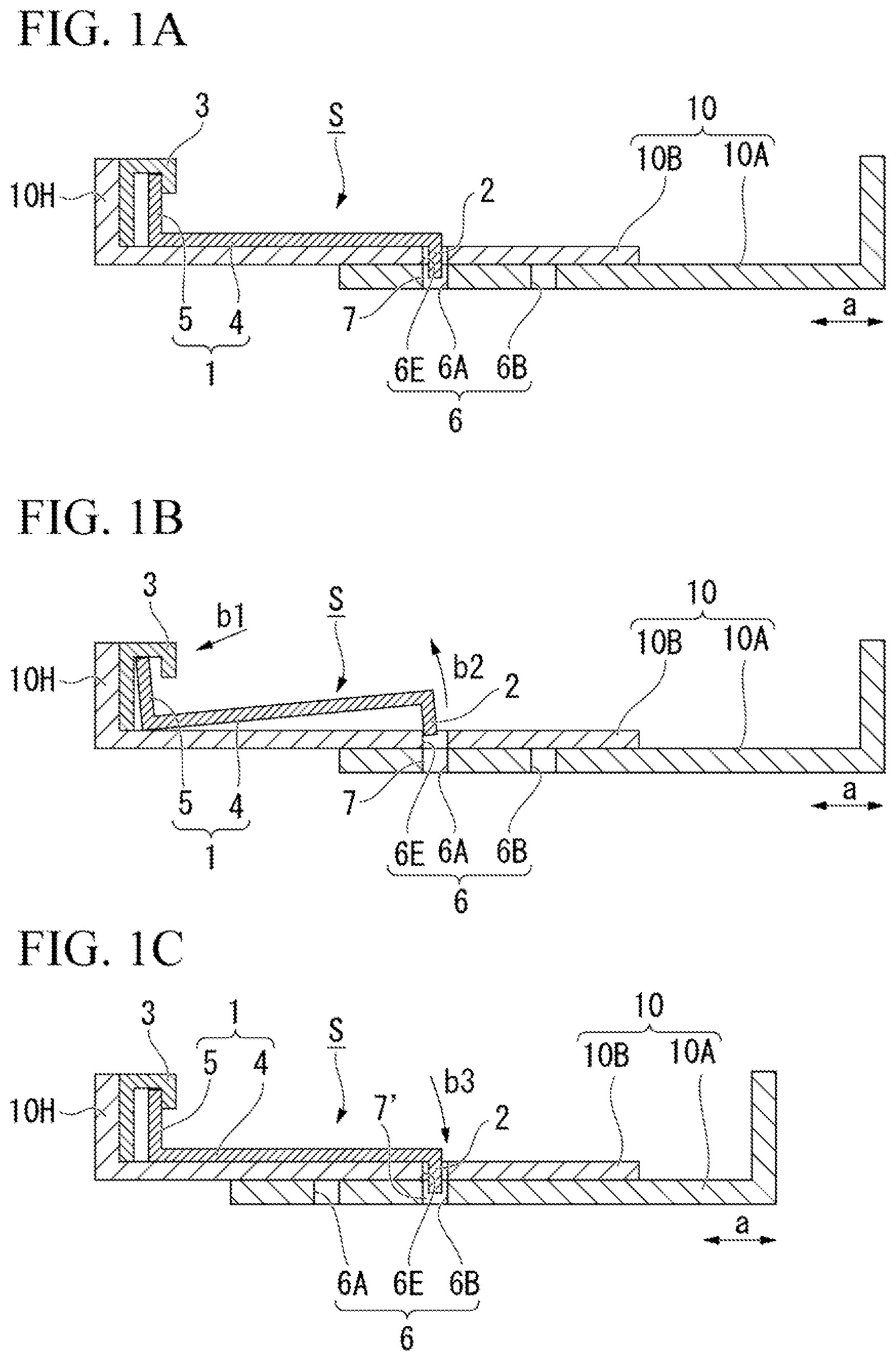
A is a schematic diagram showing a minimum configuration of a retractable tray and a retractable tray fixing device according to the present disclosure, in which a step of operations is shown.
B is a schematic diagram showing a minimum configuration of a retractable tray and a retractable tray fixing device according to the present disclosure, in which a step of operations is shown.
C is a schematic diagram showing a minimum configuration of a retractable tray and a retractable tray fixing device according to the present disclosure, in which a step of operations is shown.
A is a diagram showing an example embodiment of the present disclosure, which is a plan view of the retractable tray and the retractable tray fixing device according to the present disclosure.
B is a diagram showing an example embodiment of the present disclosure, which is a cross-sectional view along line X-X in A .
shows a perspective view of A .
is a perspective view showing the retractable tray fixing device of .
is a perspective view showing an operation of the retractable tray fixing device of .
A is a diagram showing the retractable tray with its length extended, which is a plan view.
B is a diagram showing the retractable tray with its length extended, which is a cross-sectional view along line Y-Y in A .
is a front cross-sectional view of a case in which a knob portion of a latch is pushed toward a wall portion of the tray.
is a plan view of the retractable tray with its length extended.
A is a front cross-sectional view of a case in which the knob portion of the latch is pressed with a fingertip.
B is a front cross-sectional view of a case in which the fingertip is removed from the knob portion of the latch.
A is a diagram showing a modified example of the example embodiment of the present disclosure, which is a plan view of a retractable tray and a retractable tray fixing device.
B is a diagram showing a modified example of the example embodiment of the present disclosure, which is a cross-sectional view along line Z-Z in A .
A is a cross-sectional view showing an operation of the retractable tray fixing device shown in A and 10 B , which is a diagram showing a fixed pattern 1 .
B is a cross-sectional view showing an operation of the retractable tray fixing device shown in A and 10 B , which is a diagram showing a fixed pattern 2 .
EXAMPLE EMBODIMENT
A minimum configuration of a retractable tray fixing device S according to the present disclosure will be described with reference to A to 1 C .
As shown in A , a retractable tray 10 to which the present disclosure is applied has a first tray 10 A and a second tray 10 B, and is configured such that these trays 10 A and 10 B overlap each other and slide in arrow a directions, so that the overall length thereof can be changed.
This retractable tray 10 is provided with the retractable tray fixing device S having a latch 1 , a claw portion 2 , and a latch operating portion 3 .
The latch 1 includes a beam portion 4 provided along a bottom surface of the second tray 10 B and a knob portion 5 provided along a wall portion 10 H forming an edge of the second tray 10 B. The knob portion 5 is integral with the beam portion 4 .
The claw portion 2 is provided at a tip position of the beam portion 4 of the latch 1 . The claw portion 2 is inserted into and removed from a tray hole 6 penetrating the trays 10 A and 10 B (see A to 1 C ).
In addition, the tray hole 6 shown in the present example includes tray holes 6 A and 6 B formed in the first tray 10 A at intervals in sliding directions (arrow a directions) and a tray hole 6 E formed in the second tray 10 B, and by sliding the second tray 10 B relative to the first tray 10 A, the tray hole 6 E of the second tray 10 B is selectively connected to the tray hole 6 A or 6 B of the first tray 10 A (see A to 1 C ).
Also, A and 1 B show that the tray hole 6 E of the second tray 10 B is connected with the tray hole 6 A of the first tray 10 A to form a through hole 7 that passes through both trays 10 A and 10 B.
The latch operating portion 3 is made of an elastically deformable constituent material, connected to the knob portion 5 of the latch 1 , and operated by an operator's fingertip operation to insert and remove the claw portion 2 at a tip of the latch beam portion 4 from the through hole 7 of the trays 10 A and 10 B (see A and 1 B ).
Specifically, in a case in which the knob portion 5 of the latch 1 is pushed toward the wall portion 10 H of the tray 10 B by the operator's fingertip operation to elastically deform the constituent material, the latch operating portion 3 can separate the claw portion 2 at the tip of the latch beam portion 4 from the through hole 7 of the trays 10 A and 10 B (see B ).
Also, in a case in which the operator performs an operation of removing the fingertip, the latch operating portion 3 can restore the elastically deformed constituent material to its original shape and insert the claw portion 2 into the through hole 7 or 7 ′ of the trays 10 A and 10 B ( A and 1 C ).
In the retractable tray fixing device S according to the minimum configuration of the present disclosure described above, the fingertip operation (operation indicated by an arrow b 1 in B ) of pushing the knob portion 5 of the latch 1 toward the wall portion 10 H of the tray 10 B is performed in the latch operating portion 3 , and thus in a case in which the material constituting the latch operating portion 3 is elastically deformed, the claw portion 2 at the tip of the latch beam portion 4 can be separated from the through hole 7 of the trays 10 A and 10 B (movement of the claw portion 2 is indicated by an arrow b 2 ).
In this state, the claw portion 2 at the tip of the beam portion 4 of the latch 1 is partly out of the through hole 7 of the trays 10 A and 10 B, and thus the first tray 10 A and the second tray 10 B are slidable relative to each other, and the overall length of the trays can be adjusted in accordance with the size of paper (see B ).
Also, in a case in which the operation of removing the fingertip from the latch operating portion 3 is performed, the elastically deformed constituent material restores to its original shape, and as indicated by an symbol b 3 in C , the claw portion 2 of the latch beam portion 4 can be inserted into the through hole 7 ′ of the trays 10 A and 10 B after being slid.
Further, in C , an example is shown in which, after lengths of the trays 10 A and 10 B are adjusted, the tray hole 6 E of the second tray 10 B is connected to the tray hole 6 B of the first tray 10 A to form the through hole 7 ′ passing through both the trays 10 A and 10 B.
Thus, the first tray 10 A and the second tray 10 B after the length of the entire tray is adjusted are fixed to each other again by the latch 1 (see C ).
That is, in the retractable tray fixing device S according to the minimum configuration of the present disclosure, it is possible to perform fixing and releasing of the retractable first and second trays 10 A and 10 B with a simple operation using only a fingertip of one hand of the operator, and to keep the number of components to a necessary minimum by using simple constituent elements, thereby achieving cost reduction.
In addition, in the retractable tray fixing device S according to the minimum configuration of the present disclosure, since it is not necessary to move the trays 10 A and 10 B up and down when the first tray 10 A and the second tray 10 B are fixed and released, it is possible to achieve space saving in the overall structure.
EXAMPLE EMBODIMENTS
The configuration of a retractable tray fixing device S 1 according to an example embodiment of the present disclosure will be described with reference to A to 11 B.
As shown in A to 3 , a retractable tray 100 shown in the example embodiment has a first tray 100 A and a second tray 100 B.
The first tray 100 A is a tray serving as a base. The second tray 100 B overlaps an upper surface of the first tray 100 A and is provided slidably in arrow A directions, so that the entire length of the retractable tray 100 can be changed by sliding them in the same directions.
Also, sliding means 20 are provided on the first tray 100 A and the second tray 100 B.
The sliding means 20 each include a guide rail 21 that passes through the second tray 100 B and extends in the arrow A directions, which are sliding directions, a guide pin 22 that moves along the guide rail 21 , and a pin support member 23 fixed on the first tray 100 A to hold the guide pin 22 .
In addition, in the sliding means 20 , the guide pins 22 are relatively moved along the guide rails 21 , so that the second tray 100 B can be slid in the arrow A directions on the first tray 100 A.
Also, although three sets of sliding means 20 are provided in the present example, it is preferable to provide a plurality of sets, at least two sets of them.
The retractable tray 100 is provided with the retractable tray fixing device S 1 having a latch 11 , a claw portion 12 , and a latch operating portion 13 .
As shown in detail in , the latch 11 is a structure in which a beam portion 14 provided along a bottom surface of the second tray 100 B and a knob portion 15 provided along a wall portion 100 H forming an edge of the second tray 100 B, are formed as an integral member via a bent portion 16 to be movable. Thus, the knob portion 15 is provided integrally with the beam portion 14 .
Also, in the latch 11 of the present example, the beam portion 14 is formed to be long, the knob portion 15 is formed to be short, and they are integrally molded with the bent portion 16 interposed therebetween to form an L-shape as a whole.
In addition, as shown in , in the latch 11 , the knob portion 15 and the beam portion 14 are vertically swingable about a horizontal axis (indicated by reference numeral 16 A) in the bent portion 16 located on the bottom surface of the second tray 100 B.
Further, the height of the knob portion 15 of the latch 11 is formed to be approximately the same as the height of the wall portion 100 H of the second tray 100 B on which the knob portion 15 is provided.
Also, the wall portion 100 H of the second tray 100 B is disposed in a positional relationship in which it is perpendicular to the bottom surface of the second tray 100 B.
Further, the latch claw portion 12 is provided at a lower tip position of the latch beam portion 14 and is disposed to be insertable into and removable from the tray holes 17 passing through the trays 100 A and 100 B.
The tray holes 17 include a plurality of tray holes 17 A and 17 B (two in the present example) formed individually at intervals in the sliding directions (arrow A directions) in the first tray 100 A, and a common tray hole 17 E formed in the second tray 100 B.
In addition, in the retractable tray 100 as described above, by sliding the second tray 100 B in the arrow A directions relative to the first tray 100 A, the tray hole 17 E of the second tray 100 B is selectively connected to either the tray hole 17 A or 17 B of the first tray 100 A (see A to 9 B ).
As a specific example, A to 7 illustrate that the tray hole 17 E of the second tray 100 B is connected to the tray hole 17 A of the first tray 100 A such that their axes are aligned with each other, and thus an integral through hole D 1 that is continuous while penetrating both trays 100 A and 100 B is formed.
Moreover, to 9 B illustrate that the tray hole 17 E of the second tray 100 B is connected to the tray hole 17 B of the first tray 100 A such that their axes are aligned with each other, and thus an integral through hole D 2 that is continuous while penetrating both trays 100 A and 100 B is formed.
The latch operating portion 13 is made of an elastically deformable constituent material, connected to the knob portion 15 of the latch 11 , and operated by the operator's fingertip operation to insert and remove the claw portion 12 at the tip of the latch beam portion 14 into and from the through hole D 1 or D 2 of the trays 100 A and 100 B.
Specifically, as shown in detail in , the latch operating portion 13 has fixed portions 30 provided along the latch beam portion 14 and an standing portion 31 provided along the knob portion 15 of the latch 11 , and the fixed portions 30 and the standing portion 31 are integrally formed via a bent portion 32 connecting them to each other to form an L-shape as a whole.
The fixed portions 30 are located on both sides of the beam portion 14 to sandwich the latch beam portion 14 and are fixed onto the second tray 100 B via attachment holes 30 B by fixing means 30 A including screws, bolts (not shown), and the like (see ).
The height of the standing portion 31 is formed to be approximately the same as the height of the wall portion 100 H of the second tray 100 B, similarly to the knob portion 15 of the latch 11 .
An elastically deformable bent portion 33 is provided at a tip of the standing portion 31 , and the knob portion 15 of the latch 11 is connected to an inner side of the bent portion 33 .
In addition, in the latch operating portion 13 , in a case in which the knob portion 15 of the latch 11 is pushed toward the wall portion 100 H of the second tray 100 B while the bent portion 33 is elastically deformed by the operator's fingertip operation, the claw portion 12 at the tip of the latch beam portion 14 can be separated from the through hole D 1 or D 2 of the trays 100 A and 100 B.
Further, in a case in which the operator performs an operation of removing the fingertip from the bent portion 33 , the latch operating portion 13 restores the elastically deformed bent portion 33 to its original shape, so that the claw portion 12 can be inserted into the through hole D 1 or D 2 of the trays 100 A and 100 B (which will be described later with reference to to 9 B ).
In the retractable tray fixing device S 1 according to the present example embodiment described above, in a case in which an operation of the fingertip (operation of a fingertip U indicated by an arrow B 1 in ) is performed to push the knob portion 15 of the latch 11 toward the wall portion 100 H of the tray 100 B in the bent portion 33 of the latch operating portion 13 and the constituent material of the latch operating portion 13 is elastically deformed, the claw portion 12 at the tip of the latch beam portion 14 can be separated from the through hole D 1 of the trays 100 A and 100 B (movement of the claw portion 12 is indicated by an arrow B 2 ).
In this state, since the claw portion 12 at the tip of the latch beam portion 14 is out of the through hole D 1 of the trays 100 A and 100 B, the restriction on the movement of the retractable tray 100 is released.
Thus, the first tray 100 A and the second tray 100 B can slide relative to each other, and the overall length of the trays can be adjusted in accordance with the size of the paper (see A, 6 B and 8 ).
In addition, in a case in which the operation of removing the fingertip U from the latch operating portion 13 is performed, the elastically deformed constituent material restores to its original shape, and as indicated by reference numeral B 3 in A and 9 B , the claw portion 12 of the latch beam portion 14 can be inserted into the through hole D 2 of the trays 100 A and 100 B after being slid.
Thus, the first tray 100 A and the second tray 100 B after the length of the entire trays is adjusted are again fixed to each other by the latch 11 (see B ).
That is, in the retractable tray fixing device S 1 according to the example embodiment, it is possible to perform fixing and releasing of the retractable first tray 100 A and second tray 100 B with a simple operation using only the fingertip U of one hand of the operator, and to keep the number of component to the necessary minimum by using simple constituent elements, thereby achieving cost reduction.
Further, in the retractable tray fixing device S 1 , since it is not necessary to move the trays 100 A and 100 B up and down when the first tray 100 A and the second tray 100 B are fixed and released, it is also possible to achieve space saving in the overall structure.
As a result, in the retractable tray fixing device S 1 , a thin tray with a thickness of about 10 mm that can be expanded and contracted can be realized with a simple structure.
Modified Example 1
In the retractable tray 100 shown in the above example embodiment, two tray holes 17 ( 17 A and 17 B) are provided in the first tray 100 A at intervals in the sliding directions (arrow A directions), but the number is not limited to two.
For example, in the retractable tray 100 shown in A to 11 B , four tray holes 17 ′ ( 17 A to 17 D) are provided in the first tray 100 A at regular intervals in the sliding directions (arrow A directions).
Thus, in the retractable tray 100 , as shown in B , it is illustrated that the tray hole 17 E of the second tray 100 B is connected to the tray hole 17 A of the first tray 100 A such that their axes are aligned with each other, and thus a through hole D 3 penetrating both the trays 100 A and 100 B is formed.
Also, in the retractable tray 100 , as shown in A , it is illustrated that the tray hole 17 E of the second tray 100 B is connected to the tray hole 17 B of the first tray 100 A such that their axes are aligned with each other, and thus a through hole D 4 penetrating both the trays 100 A and 100 B is formed.
In addition, in the retractable tray 100 , as shown in B , it is illustrated that the tray hole 17 E of the second tray 100 B is connected to the tray hole 17 C of the first tray 100 A such that their axes are aligned with each other, and thus a through hole D 5 penetrating both the trays 100 A and 100 B is formed.
As a result, in the retractable tray 100 shown in A to 11 B , the lengths of the trays 100 A and 100 B can be set in multiple stages, and various types of paper can be handled.
Modified Example 2
In the above example embodiment, the latch 11 is made swingable around the horizontal axis 16 A (see ) located on a tangential line between the second tray 100 B and the bent portion 16 of the latch 11 . This horizontal axis 16 A may be constituted by an actual shaft body to rotatably support the latch 11 .
Modified Example 3
In the above example embodiment, the bent portion 33 of the latch operating portion 13 is provided to be connected to the knob portion 15 of the latch 11 . In this case, the latch operating portion 13 and the latch 11 may be integrally molded with the same member, or may be formed as individual bodies.
As described above, the example embodiment of the present disclosure has been described in detail with reference to the drawings, but specific configurations are not limited to this example embodiment, and design changes and the like are also included within the scope of the present disclosure.
An example object of the present disclosure is to provide a retractable tray fixing device and a fixing method in which it is possible to perform fixing and releasing of a tray with a simple one-handed operation and to minimize the number of components, thereby enabling space saving and cost reduction.
In the present disclosure, it is possible to perform fixing and releasing of the retractable first and second trays with a simple operation using only a fingertip of one hand of the operator, and to keep the number of components to a necessary minimum by using simple constituent elements, thereby achieving space saving and cost reduction.
The present disclosure relates to a retractable tray fixing device and a fixing method in which lengths of two trays can be freely reduced or increased depending on the intended uses.
Figures (9)
Citations
This patent cites (13)
- US8387971
- US9242813
- US9422123
- US9511961
- US10479626
- US2016/0009514
- US1841221
- USH02-103032
- USH04-132766
- USH06-144598
- USH08-301461
- US3600407
- US2015/194503