Mask Inspection Apparatus and Method for Inspecting a Mask Having First and Second Openings
Abstract
A mask inspection method and a mask inspection apparatus for inspecting a deposition mask are provided. A mask inspection method includes: providing a deposition mask including a plurality of first openings and a plurality of second openings, each of the first openings having a shape in a plan view different from that of each of the second openings; designating a first group and a second group, each including at least one of the first openings and at least one of the second openings; comparing an image of the first group with an image of the second group; and determining whether the first group and the second group are defective, an arrangement of the first and second openings of the first group being the same as an arrangement of the first and second openings of the second group.
Claims (8)
1. A mask inspection method comprising: providing a deposition mask comprising a plurality of first openings and a plurality of second openings, each of the first openings having a same shape in a plan view and different from that of each of the second openings, the deposition mask comprising a first surface and a second surface opposite the first surface, a second side end of each of the first openings located at the second surface surrounding a first side end of the respective first opening located at the first surface, and a second side end of each of the second openings located at the second surface surrounding a first side end of the respective second opening located at the first surface; designating a first group and a second group, each comprising at least one of the first openings and at least one of the second openings; comparing an image of the first group with an image of the second group; and determining whether the first group and the second group are defective based on a result of comparing the image of the first group with the image of the second group, wherein an arrangement of the first and second openings of the first group is the same as an arrangement of the first and second openings of the second group and rotated in the plan view.
Show 7 dependent claims
2. The mask inspection method of claim 1 , wherein the comparing of the image of the first group and the image of the second group comprises comparing an area of the first group with an area of the second group.
3. The mask inspection method of claim 2 , further comprising, before the comparing of the image of the first group and the image of the second group, imaging the first group and the second group by using a vision unit including a charge-coupled device sensor comprising a plurality of pixels to acquire an image of the first group and an image of the second group.
4. The mask inspection method of claim 3 , wherein the comparing of the area of the first group and the area of the second group comprises comparing a number of a part of the pixels of the charge-coupled device sensor arranged within the first group with a number of another part of the pixels of the charge-coupled device sensor arranged within the second group.
5. The mask inspection method of claim 1 , wherein the comparing of the image of the first group and the image of the second group comprises comparing a shape of the first group with a shape of the second group.
6. The mask inspection method of claim 5 , further comprising imaging the first group and the second group by using a vision unit comprising a charge-coupled device sensor comprising a plurality of pixels, wherein the comparing of the shape of the first group and the shape of the second group comprises comparing a shape of a part of the pixels of the charge-coupled device sensor arranged within the first group with a shape of another part of the pixels of the charge-coupled device sensor arranged within the second group.
7. The mask inspection method of claim 6 , wherein the comparing of the image of the first group and the image of the second group further comprises rotating any one of the image of the first group and the image of the second group in a horizontal direction.
8. The mask inspection method of claim 5 , wherein the comparing of the image of the first group and the image of the second group comprises comparing with naked eyes of an inspector.
Full Description
Show full text →
CROSS-REFERENCE TO RELATED APPLICATION
This application claims priority to and the benefit of Korean Patent Application No. 10-2020-0079076, filed on Jun. 29, 2020 in the Korean Intellectual Property Office, the entire content of which is herein incorporated by reference.
BACKGROUND
1. Field
Aspects of embodiments of the present disclosure relate to a mask inspection apparatus and a mask inspection method.
2. Description of the Related Art
Typically, an organic light emitting diode (OLED) display is attracting attention as a next generation flat panel display device due to its excellent luminance and viewing angle characteristics and, unlike a liquid crystal display device, no requirement of any separate light source. With the elimination of the necessity for any separate light source, the OLED display can be manufactured having a lightweight and thin design. The OLED display is also characterized by low power consumption, high luminance, high reaction rate, and the like.
The OLED display includes a plurality of organic light emitting diodes, each being composed of an anode, an organic light emitting layer, and a cathode. During a process of manufacturing the organic light emitting diodes, a deposition mask is disposed on a substrate, and an organic material is provided onto the substrate through openings formed in the deposition mask to form organic light emitting layers. With the advance of technologies, a display device has an increasing number of organic light emitting diodes to meet a high resolution requirement.
The increasing number of organic light emitting diodes means that the number of openings of the deposition mask for use in manufacturing the organic light emitting layers is increased. Such a deposition mask is formed with a material including a metal, and, due to manufacturing problems, it is possible that not all of the plurality of openings have accurate shapes as desired in a pattern. This may cause a defect in the deposition pattern. In order to avoid such a defect, the mask is inspected in advance.
SUMMARY
According to aspects of embodiments of the present disclosure, a mask inspection apparatus and method that are capable of inspecting a mask with openings of different shapes for any defect at one time are provided.
However, aspects of the present disclosure are not restricted to those set forth herein. The above and other aspects of the present disclosure will become more apparent to one of ordinary skill in the art to which the present disclosure pertains by referencing the detailed description of the present disclosure provided below.
According to one or more embodiments, a mask inspection method includes: providing a deposition mask including a plurality of first openings and a plurality of second openings, each of the first openings having a shape in a plan view different from that of each of the second openings; designating a first group and a second group, each including at least one of the first openings and at least one of the second openings; comparing an image of the first group with an image of the second group; and determining whether the first group and the second group are defective based on a result of comparing the image of the first group with the image of the second group, wherein an arrangement of the first and second openings of the first group is the same as an arrangement of the first and second openings of the second group.
According to one or more embodiments, a mask inspection method includes: providing a deposition mask including a plurality of first openings and a plurality of second openings, each of the first openings having a shape in a plan view different from that of each of the second openings; preparing a reference image including first openings of the plurality of first openings and second openings of the plurality of second openings; designating a plurality of groups, each comprising first openings of the plurality of first openings and second openings of the plurality of second openings; comparing an image of a group of the plurality of groups with the reference image; and determining whether the group is defective based on a result of comparing the image of the group with the reference image, wherein an arrangement of the first and second openings of the group is the same as an arrangement of the first and second openings of the reference image.
According to one or more embodiments, a mask inspection apparatus for inspecting a deposition mask including a plurality of first openings and a plurality of second openings each having a shape in a plan view different from that of each of the first openings includes: a supporting table configured to support the deposition mask; a vision unit spaced apart from the supporting table and configured to capture an image of the deposition mask; and a controller configured to determine whether the first and second openings are defective based on the image captured by the vision unit, wherein the controller designates a first group and a second group, each including at least one of the first openings and at least one of the second openings, and compares a first image obtained by imaging the first group with a second image obtained by imaging the second group.
The mask inspection apparatus and method according to embodiments are capable of inspecting a mask with openings of different shapes for any defect at one time.
However, aspects and effects of the present disclosure are not limited to the aforementioned aspects and effects, and various other aspects and effects are included in the present specification.
BRIEF DESCRIPTION OF THE DRAWINGS
The above and other aspects and features of the present disclosure will become more apparent by describing in further detail some example embodiments thereof with reference to the attached drawings, in which:
is a side view schematically showing a mask inspection apparatus according to an embodiment;
is an enlarged plan view of a partial area of a mask;
is a cross-sectional view taken along the line III-Ill′ of ;
is a view schematically illustrating a deposition process using the deposition mask of ;
is a cross-sectional view schematically illustrating an organic light emitting display device manufactured with a deposition mask;
is a flowchart illustrating a mask inspection method according to an embodiment;
is a plan view schematically illustrating a mask inspection method according to an embodiment;
is a plan view schematically illustrating a mask inspection method according to another embodiment;
is schematic layout view illustrating a pixel arrangement of a display device according to another embodiment;
is a plan view schematically illustrating a mask inspection method according to another embodiment;
is a schematic layout view illustrating a pixel arrangement of a display device according to another embodiment;
is a side view schematically illustrating a mask inspection apparatus according to another embodiment; and
is a flowchart illustrating a mask inspection method according to another embodiment.
DETAILED DESCRIPTION
The present invention will now be described more fully herein with reference to the accompanying drawings, in which some example embodiments of the invention are shown. The present invention may, however, be embodied in different forms and should not be construed as limited to the embodiments set forth herein. Rather, these embodiments are provided so that this disclosure will be thorough and complete, and will fully convey the scope of the invention to those skilled in the art.
It is to be understood that when a layer is referred to as being “on” another layer or substrate, it may be directly on the other layer or substrate, or one or more intervening layers may also be present. The same reference numbers indicate the same components throughout the specification. In the attached figures, the thicknesses of layers and regions may be exaggerated for clarity.
Although the terms “first,” “second,” etc. may be used herein to describe various elements, these elements should not be limited by these terms. These terms may be used to distinguish one element from another element. Thus, a first element discussed below may be termed a second element without departing from the teachings of one or more embodiments. The description of an element as a “first” element may not require or imply the presence of a second element or other elements. The terms “first,” “second,” etc. may also be used herein to differentiate different categories or sets of elements. For conciseness, the terms “first,” “second,” etc. may represent “first-category (or first-set),” “second-category (or second-set),” etc., respectively.
It is to be understood that when an element or layer is referred to as being “on,” “connected to,” “coupled to,” or “adjacent to” another element or layer, it may be directly on, connected to, coupled to, or adjacent to the other element or layer, or one or more intervening elements or layers may be present. In contrast, when an element or layer is referred to as being “directly on,” “directly connected to,” “directly coupled to,” or “immediately adjacent to” another element or layer, there are no intervening elements or layers present. As used herein, the terms “substantially,” “about,” and similar terms are used as terms of approximation and not as terms of degree, and are intended to account for the inherent deviations in measured or calculated values that would be recognized by those of ordinary skill in the art.
As used herein, phrases such as “a plan view” may refer to a view from top or from a direction normal to the display area of the display device.
Spatially relative terms, such as “beneath,” “below,” “lower,” “above,” “upper,” “bottom,” “top,” and the like, may be used herein for ease of description to describe one element or feature's relationship to another element(s) or feature(s) as illustrated in the figures. It is to be understood that the spatially relative terms are intended to encompass different orientations of the device in use or operation in addition to the orientation depicted in the figures. For example, if the device in the figures is turned over, elements described as “below” or “beneath” other elements or features would then be oriented “above” or “over” the other elements or features. Thus, the term “below” may encompass both an orientation of above and below. The device may be otherwise oriented (e.g., rotated 90 degrees or at other orientations), and the spatially relative descriptors used herein should be interpreted accordingly.
Unless otherwise defined, all terms (including technical and scientific terms) used herein have the same meaning as commonly understood by one of ordinary skill in the art to which the present disclosure belongs. It is to be further understood that terms, such as those defined in commonly used dictionaries, should be interpreted as having a meaning that is consistent with their meaning in the context of the relevant art and/or the present disclosure, and should not be interpreted in an idealized or overly formal sense, unless expressly so defined herein.
Herein, some example embodiments will be described in further detail with reference to the accompanying drawings.
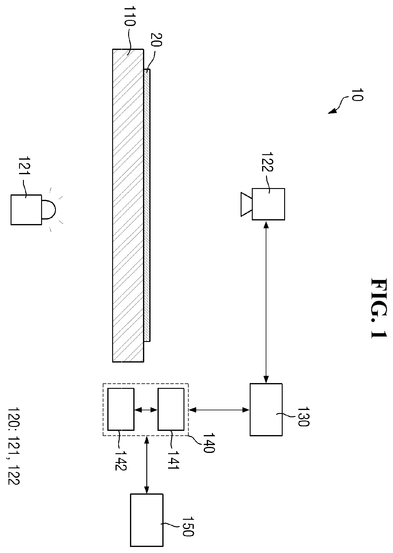
is a side view schematically showing a mask inspection apparatus according to an embodiment.
Referring to , a mask inspection apparatus 10 according to an embodiment may include a supporting table 110 , a vision unit 120 , a data processing unit 130 , a controller 140 , and an output unit 150 .
The supporting table 110 may provide a space in which a deposition mask 20 as an inspection target object can be placed. That is, the deposition mask 20 may be placed on the supporting table 110 . The supporting table 110 may include a transparent glass or the like, allowing light emitted from a light irradiation member 121 to pass therethrough.
The supporting table 110 may fix the deposition mask 20 in a stretched state, although the present disclosure is not limited thereto. In this case, in an embodiment, the supporting table 110 may include clamps (not shown) for fixing both ends of the deposition mask 20 and a cylinder or gear and a motor for moving the clamps (not shown) linearly to stretch the deposition mask 20 . The supporting table 110 may further include a mask frame (not shown) and, in this case, the deposition mask 20 may be attached to the mask frame (not shown), but the present disclosure is not limited thereto.
In an embodiment, although not shown in the drawing, the mask inspection apparatus 10 may further include a transfer member (not shown), and the supporting table 110 may be connected to the transfer member (not shown) and transferred by the transfer member (not shown).
The vision unit 120 may be arranged above and/or below the deposition mask 20 to capture an image of a surface shape of the deposition mask 20 . The vision unit 120 may be spaced apart from the supporting table 110 and the deposition mask 20 . The vision unit 120 may generate an image by imaging the deposition mask 20 and send the image to the controller 140 . In an embodiment, the vision unit 120 may include the light irradiation member 121 and a light receiving member 122 .
The light irradiation member 121 may be arranged below the supporting table 110 to emit light toward the supporting table 110 . The light irradiation member 121 may emit the light towards the deposition mask 20 placed on the supporting table 110 .
The light receiving member 122 may be arranged above the supporting table 110 . The light receiving member 122 may face the light irradiation member 121 with the deposition mask 20 interposed therebetween. The light receiving member 122 may receive the light emitted from the light irradiation member 121 to capture an image of the deposition mask 20 . That is, at least part of the light emitted from the light irradiation member 121 may pass through openings OP 1 and OP 2 (see ) of the deposition mask 20 and reach the light receiving member 122 such that the light receiving member 122 may take an image of the deposition mask 20 .
The light receiving member 122 may include a charge-coupled device (CCD) sensor, although not limited thereto. In a case in which the light receiving member 122 includes a CCD sensor, the CCD sensor may be a two-dimensional sensor including an image capture area in which a number (e.g., a predetermined number) of pixels are arranged. For example, the CCD sensor may have an image capture area of 2048×512 pixels (144 μm×36 μm in a case in which one pixel is 70 nm×70 nm), although not limited thereto. That is, the CCD sensor may be composed of a plurality of row lines (e.g., 512 lines) arranged in a direction, each line being composed of a plurality of pixels (e.g., 2048 pixels).
The data processing unit 130 may process information of the image captured by the vision unit 120 . The data processing unit 130 may convert the image information received from the vision unit 120 into a format fit for transmission and transmit the converted image information to the controller 140 . In an embodiment, the data processing unit 130 may provide the controller 140 with necessary information in a wireline or wireless communication scheme.
The controller 140 may designate opening groups GR 1 to GR 6 (see ) including openings OP 1 and OP 2 of different shapes based on the data (image information) received from the data processing unit 130 and determine whether the deposition mask 20 is defective. The controller 140 may include a comparison unit 141 for comparison of the data (image information) and a determination unit 142 for determining presence/absence of any defect based on the comparison result.
Although not limited to the following, the method for the controller 140 to determine whether the deposition mask 20 is defective may, for example, include comparing the images obtained by imaging the same pattern at different locations (die-to-die comparison inspection method), or comparing an image obtained by imaging a pattern of an actual mask with a reference image generated based on plan data used in forming the deposition mask 20 (die-to-database comparison inspection method). The method for inspecting the deposition mask 20 is described later.
The controller 140 may take any of various forms. Although not limited to the following, the controller 140 may be provided, for example, in the form of a terminal, a personal computer, a laptop computer, or a PDA, which is installed separately, or in the form of a circuit board, which is installed internally with other components, rather than a separate device.
The output unit 150 may output information indicating whether the deposition mask 20 is defective as determined by the controller 140 . The output unit 150 may output the information of the openings determined as normal and the openings determined as defective among the openings OP 1 and OP 2 (see ) of the deposition mask 20 . The information of the output unit 150 may include coordinates information indicative of the locations of the openings determined as defective among the openings OP 1 and OP 2 (see ) of the deposition mask 20 . Accordingly, a user may selectively correct the defective openings into the normal openings or, in a case in which a number of defective openings is equal to or greater than a certain number (e.g., a predetermined number), replace the deposition mask 20 with a new one and proceed to perform the deposition process.
The deposition mask 20 may include two or more openings OP 1 and OP 2 that differ in shape in a plan view. The deposition mask 20 is described in further detail with reference to .
is an enlarged plan view of a partial area of a mask; and is a cross-sectional view taken along the line III-III′ of .
Referring to , in the drawings, a first direction DR 1 indicates a horizontal direction of the deposition mask 20 in a plan view, and a second direction DR 2 indicates a vertical direction of the deposition mask 20 in a plan view. Further, a third direction DR 3 indicates a thickness direction of the deposition mask 20 . The first direction DR 1 and the second direction DR 2 perpendicularly intersect each other. The third direction DR 3 is a direction intersecting a plane on which the first direction DR 1 and the second direction DR 2 are located, and perpendicularly intersects both the first direction DR 1 and the second direction DR 2 . It should be understood, however, that a direction mentioned in an embodiment refers to a relative direction and the embodiment is not limited to the direction mentioned.
The deposition mask 20 includes a blocking portion BL and a plurality of openings OP 1 and OP 2 formed inside the blocking portion BL. The blocking portion BL may block permeation of a deposition material. The blocking portion BL may include a blocking member. The blocking member may include a metal, such as any of nickel (Ni), a nickel alloy, and a nickel-cobalt alloy, for example. The blocking member may be provided in the form of a thin metal film, but is not limited thereto.
The openings OP 1 and OP 2 are formed inside the blocking portion BL, in a shape of penetrating a material layer constituting the blocking portion BL in the thickness direction (third direction DR 3 ). The openings OP 1 and OP 2 allow the deposition material to pass therethrough such that a pattern having a shape corresponding to the openings OP 1 and OP 2 may be formed on a target substrate 330 (see ).
The deposition mask 20 may have a first surface 20 a and a second surface 20 b . The first and second surfaces 20 a and 20 b of the deposition mask 20 may be opposite surfaces. Although not limited to the following, for example, the first surface 20 a of the deposition mask 20 may be a surface facing the target substrate 330 (see ), and the second surface 20 b opposite to the first surface 20 a may be a surface facing a crucible.
The deposition mask 20 may further include a first inside surface S 1 and a second inside surface S 2 . The first inside surface S 1 may face the first opening OP 1 in the blocking portion BL, and the second inside surface S 2 may face the second opening OP 2 in the blocking portion BL. That is, the inner wall of the first opening OP 1 may include the first inside surface S 1 , and the inner wall of the second opening OP 2 may include the second inside surface S 2 .
The deposition mask 20 may further include a first first side end BE 1 , a first second side end UE 1 , a second first side end BE 2 , and a second second side end UE 2 . The first first side end BE 1 may denote a portion where the first surface 20 a of the deposition mask 20 and the first inside surface S 1 meet, and the first second side end UE 1 may denote a portion where the second surface 20 b of the deposition mask 20 and the first inside surface S 1 meet. The second first side end BE 2 may denote a portion where the first surface 20 a of the deposition mask 20 and the second inside surface S 2 meet, and the second second side end UE 2 may denote a portion where the second surface 20 b of the deposition mask 20 and the second inside surface S 2 meet.
The openings OP 1 and OP 2 of the deposition mask 20 may differ in shape in a plan view. The openings OP 1 and OP 2 of the deposition mask 20 may have two or more different kinds of shapes in a plan view. The deposition mask 20 may include two or more openings OP 1 and OP 2 that differ in shape in a plan view. The deposition mask 20 may include the first openings OP 1 and the second openings OP 2 that differ in shape in a plan view.
The first first side end BE 1 may be surrounded by the first second side end UE 1 in a plan view, and the shape of the first first side BE 1 and the shape of the first second side end UE 1 may correspond to each other in a plan view. The second first side end BE 2 may be surrounded by the second second side end UE 2 in a plan view, and the shape of the second first side end BE 2 and the shape of the second second side end UE 2 may correspond to each other in a plan view. That is, the first first side end BE 1 and the second first side end BE 2 may differ in shape in a plan view, and the first second side end UE 1 and the second second side end UE 2 may differ in shape in a plan view.
In an embodiment, the first and second openings OP 1 and OP 2 may be spaced apart from each other and alternately arranged along the first and second directions DR 1 and DR 2 . That is, in an embodiment, the first and second openings OP 1 and OP 2 may be alternately arranged in a repetitive manner in the first direction DR 1 , and the first and second openings OP 1 and OP 2 may be alternately arranged in a repetitive manner in the second direction DR 2 .
In an embodiment, at least a part of the plurality of first openings OP 1 may be arranged in a state of being rotated in a range greater than 0 degrees and less than 360 degrees in a clockwise direction in a plan view. In another embodiment, at least a part of the plurality of first openings OP 1 may be arranged to be (in the drawings) reversed left and right in the first direction DR 1 or up and down in the second direction DR 2 . Likewise, in an embodiment, at least a part of the plurality of second openings OP 2 may be arranged in a state of being rotated in a range greater than 0 degrees and less than 360 degrees in the clockwise direction in a plan view. In another embodiment, at least a part of the plurality of second openings OP 2 may be arranged to be (in the drawings) reversed left and right in the first direction DR 1 or up and down in the second direction DR 2 .
The deposition mask 20 may further include an opening group GR. In an embodiment, the opening group GR may include one first opening OP 1 and one second opening OP 2 , but the present disclosure is not limited thereto. That is, the deposition mask 20 may include the first and second openings OP 1 and OP 2 that are repeatedly arranged, and may include the opening groups GR, each including one first opening OP 1 and one second opening OP 2 .
The opening groups GR may be repeatedly arranged along the first and second directions DR 1 and DR 2 . In an embodiment, a part of the opening groups GR may be arranged in a state of being rotated in a range greater than 0 degrees and less than 360 degrees in the clockwise direction in a plan view. In another embodiment, a part of the opening groups GR may be arranged to be (in the drawings) reversed left and right in the first direction DR 1 or up and down in the second direction DR 2 .
Although it is shown in that the openings OP 1 and OP 2 have example shapes in plan and cross-sectional views, the shapes thereof are not limited thereto.
is a view schematically illustrating a deposition process using the deposition mask of .
Referring to , according to an embodiment, a process of depositing an electrode or an organic light emitting layer of an organic light emitting display device may be performed in a vacuum chamber 300 .
A deposition source 310 may be disposed at a lower portion inside the vacuum chamber 300 . The deposition source 310 may be, for example, a crucible as a container in which a deposition material is contained. The deposition mask 20 according to an embodiment may be placed on a supporting structure 320 at an upper portion inside the vacuum chamber 300 that faces the deposition source 310 . In an embodiment, the target substrate 330 , e.g., the target substrate 330 for manufacturing an organic light emitting display device, may be arranged on the deposition mask 20 . In an embodiment, the deposition mask 20 and the target substrate 330 may be in direct contact with each other.
When the deposition source 310 evaporates the deposition material onto the deposition mask 20 inside the aforementioned vacuum chamber 300 , the deposition material may be deposited on parts of the target substrate 330 that are exposed through the openings OP 1 and OP 2 (see ) formed in the deposition mask 20 according to the shapes of the pattern.
is a cross-sectional view schematically illustrating an organic light emitting display device manufactured with a deposition mask.
Referring to , a display device 400 may include a base substrate 401 . The base substrate 401 may support components stacked on the base substrate 401 . The base substrate 401 may be an insulating substrate. In an embodiment, the base substrate 401 may include a transparent material.
A buffer layer 405 may be disposed on the base substrate 401 . The buffer layer 405 may be disposed on a surface of the base substrate 401 to protect a thin film transistor TFT and a light emitting element EMD from moisture penetrating through the base substrate 401 susceptible to moisture permeation.
The thin film transistor TFT may be disposed as a driving element on the buffer layer 405 . The thin film transistor TFT may include a semiconductor layer 410 , a first insulating layer 421 , a second insulating layer 422 , and a gate electrode 430 .
The semiconductor layer 410 of the thin film transistor TFT may be disposed on the buffer layer 405 . In an embodiment, the semiconductor layer 410 may include polycrystalline silicon, monocrystalline silicon, low-temperature polycrystalline silicon, amorphous silicon, or an oxide semiconductor.
The first insulating layer 421 may be disposed on the semiconductor layer 410 . The first insulating layer 421 may be formed of an inorganic layer.
The gate electrode 430 may be disposed on the first insulating layer 421 . The gate electrode 430 may overlap the semiconductor layer 410 . In an embodiment, the gate electrode 430 may be formed as a single layer or multiple layers made of any of molybdenum (Mo), aluminum (Al), chromium (Cr), gold (Au), titanium (Ti), nickel (Ni), neodymium (Nd), and copper (Cu), or an alloy thereof.
The second insulating layer 422 may be disposed on the gate electrode 430 . The second insulating layer 422 may be formed of an inorganic layer.
A source electrode 451 (or a drain electrode) and a drain electrode 452 (or a source electrode) of the thin film transistor TFT may be disposed on the second insulating layer 422 . The source electrode 451 and the drain electrode 452 may be connected to the semiconductor layer 410 through contact holes penetrating the second insulating layer 422 and the first insulating layer 421 .
A third insulating layer 423 may be disposed on the source electrode 451 and the drain electrode 452 . The third insulating layer 423 may be a passivation layer protecting the thin film transistor TFT therebelow. The third insulating layer 423 may be formed of an inorganic layer.
A via layer VIA may be disposed on the third insulating layer 423 . The via layer VIA may be a planarization layer for flattening a step due to the thin film transistor TFT. The via layer VIA may include an organic insulating material.
The light emitting element EMD may be disposed on the via layer VIA. The light emitting element EMD may include a pixel electrode PXE, a light emitting layer EML, and a common electrode CME.
The pixel electrode PXE may be disposed on the via layer VIA. The pixel electrode PXE may be a first electrode (e.g., an anode electrode) of the light emitting element EMD. The pixel electrode PXE may be connected to the drain electrode 452 (or the source electrode) of the thin film transistor TFT through a contact hole penetrating the via layer VIA.
A pixel defining layer PDL may be disposed on the pixel electrode PXE. The pixel defining layer PDL may be disposed on the pixel electrode PXE and may include an opening to expose the pixel electrode PXE. The pixel defining layer PDL may include an organic insulating material.
The light emitting layer EML may be disposed on the pixel electrode PXE exposed by the pixel defining layer PDL. The light emitting layer EML may include an organic material layer. The organic material layer of the light emitting layer EML may include an organic light emitting layer, and may further include a hole injecting/transporting layer and/or an electron injecting/transporting layer.
The common electrode CME may be disposed on the light emitting layer EML. The common electrode CME may be a second electrode (e.g., a cathode electrode) of the light emitting element EMD. In an embodiment, the common electrode CME may be formed commonly to the pixels.
Although per-pixel or per-sub-pixel light emitting elements EMD may be arranged in different shapes in a plan view, if the deposition mask 20 has the corresponding shapes, the per-pixel or per-sub-pixel light emitting elements EMD may be deposited as parts of a common layer at one time.
In addition, the mask inspection apparatus 10 (see ) according to an embodiment may inspect the deposition mask 20 for any defect even when the deposition mask 20 includes two or more openings OP 1 and OP 2 that differ in shape from each other in a plan view. Herein, a mask inspection method according to an embodiment is further described.
is a flowchart illustrating a mask inspection method according to an embodiment; and is a plan view schematically illustrating a mask inspection method according to an embodiment.
Referring to , 6 , and 7 , first, the deposition mask 20 having the openings OP 1 and OP 2 that differ in shape is prepared or provided (S 10 ).
The deposition mask 20 may be substantially the same as the deposition mask 20 described with reference to , and placed at a location corresponding to an area (e.g., a predetermined area) on the supporting table 110 of the mask inspection apparatus 10 of . The deposition mask 20 may be moved during the process of inspecting the deposition mask 20 by the mask inspection apparatus 10 . The deposition mask 20 may be moved onto the supporting table 110 by a component independent of the supporting table 110 or fixed on the supporting table 110 to be moved along with the supporting table 110 .
Next, an inspection area IA of the deposition mask 20 is designated (S 20 ).
The inspection area IA may include the plurality of openings OP 1 and OP 2 . In an embodiment, the openings OP 1 and OP 2 within the inspection area IA may be repeatedly arranged in a pattern (e.g., a predetermined pattern). In an embodiment, the first openings OP 1 and the second openings OP 2 may be repeatedly arranged in an alternating manner along the first direction DR 1 , and the first openings OP 1 and the second openings OP 2 may be repeatedly arranged in an alternating manner along the second direction DR 2 . Although not limited to the following, adjacent openings, among the openings OP 1 and OP 2 , which are arranged within the inspection area IA may differ in shape. That is, the first and second openings OP 1 and OP 2 that differ in shape may be repeatedly arranged in an alternating manner, and may be disposed adjacent to each other.
The inspection area IA may include at least a part of an area that can be imaged at one time by the above-described vision unit 120 . That is, in a case in which the vision unit 120 includes a CCD sensor, the inspection area IA may include at least a part of the image capture area that can be imaged by the CCD sensor.
Although it is shown that twelve openings OP 1 and OP 2 are arranged within the inspection area IA, the number of the openings OP 1 and OP 2 being arranged within the inspection area IA may be greater or less than twelve. In an embodiment, task S 20 of designating the inspection area IA may be omitted.
Next, some of the repetitive openings OP 1 and OP 2 are grouped into the opening groups GR 1 to GR 6 (S 30 ).
The openings OP 1 and OP 2 arranged within the inspection area IA may be grouped by at least two adjacent openings OP 1 and OP 2 to form each opening group GR. The adjacent first and second openings OP 1 and OP 2 may, for example, be grouped into the respective groups GR 1 to GR 6 , although not limited thereto. In an embodiment, the opening groups GR 1 to GR 6 may include the same number of the openings OP 1 and OP 2 , and may include the same number of the first openings OP 1 and the same number of the second openings OP 2 . In addition, the openings OP 1 and OP 2 belonging to the respective opening groups GR 1 to GR 6 may be substantially the same in arrangement (or deployment).
In an embodiment, the individual opening groups GR 1 to GR 6 may be arranged repeatedly within the inspection area IA. That is, the opening groups GR 1 to GR 6 may be repeatedly arranged along the first and second directions DR 1 and DR 2 within the inspection area IA.
In an embodiment, the opening groups GR 1 to GR 6 may each be the smallest unit of repetition within the inspection area IA. The inspection area IA may have the first and second openings OP 1 and OP 2 disposed therein, and the first and second openings OP 1 and OP 2 may be arranged in a repetitive manner. In this case, the opening groups GR 1 to GR 6 may each include one first opening OP 1 and one second opening OP 2 , and the opening groups GR 1 to GR 6 may be arranged in a repetitive manner within the inspection area IA. The total number of the openings OP 1 and OP 2 belonging to each of the opening groups GR 1 to GR 6 may be equal to the sum of the number of the first openings OP 1 and the number of the second openings OP 2 included in each of the opening groups GR 1 to GR 6 .
The openings OP 1 and OP 2 arranged within the inspection area IA may differ in shape, and the opening groups GR 1 to GR 6 arranged within the inspection area IA may be the same in shape. That is, the opening groups GR 1 to GR 6 may each include the first and second openings OP 1 and OP 2 in the same manner, and some opening groups GR 2 and GR 5 among the opening groups GR 1 to GR 6 may be arranged in a state of being rotated by an angle (e.g., a predetermined angle) in the horizontal direction (or about an axis extending in the thickness direction (third direction DR 3 )). Although it is shown in the drawing that some opening groups GR 2 and GR 5 are rotated by 180 degrees, the rotation angle is not limited thereto.
In an embodiment, each of the opening groups GR 1 to GR 6 is the smallest unit of repetition within the inspection area IA, and may also be the smallest unit for inspecting the openings OP 1 and OP 2 of the deposition mask 20 for any defect. That is, the first and second openings OP 1 and OP 2 that differ in shape are grouped into each of the opening groups GR 1 to GR 6 to inspect the openings for any defect by one unit of each of the opening groups GR 1 to GR 6 , which may facilitate inspecting the openings of the deposition mask 20 for any defect even though the openings OP 1 and OP 2 of the deposition mask 20 differ in shape.
Next, the opening groups GR 1 to GR 6 arranged within the inspection area IA are imaged and compared (S 40 ), and it is determined whether or not the imaging result falls in a threshold range (S 50 ). As a result, it is determined whether the openings OP 1 and OP 2 arranged in the deposition mask 20 are normal or defective.
The opening groups GR 1 to GR 6 arranged within the inspection area IA are imaged by the vision unit 120 to be compared with one another. Comparing the opening groups GR 1 to GR 6 may be carried out by comparing the images obtained by imaging the opening groups GR 1 to GR 6 with one another. By comparing the areas of the opening groups GR 1 to GR 6 , it may be possible to identify an opening group including a defective opening among the opening groups GR 1 to GR 6 .
In a case in which the vision unit 120 captures an image of the opening groups GR 1 to GR 6 with the CCD sensor, pixels of the CCD sensor may be arranged within the openings OP 1 and OP 2 of the opening groups GR 1 to GR 6 on the captured image. The pixels of the CCD sensor of the vision unit 120 may be arranged at regular intervals such that the areas of the openings OP 1 and OP 2 of the opening groups GR 1 to GR 6 may be compared using the numbers of the pixels of the CCD sensor, which are arranged in the openings OP 1 and OP 2 .
The pixels of the CCD sensor may be located at the first side ends BE 1 and BE 2 of the respective openings OP 1 and OP 2 and/or at the second side ends UE 1 and UE 2 of the respective openings OP 1 and OP 2 . That is, when determining whether the openings OP 1 and OP 2 are defective, at least one of the pixels of the CCD sensor that are located at the first side ends BE 1 and BE 2 of the respective openings OP 1 and OP 2 and the pixels of the CCD sensor that are located at the second side ends UE 1 and UE 2 of the respective openings OP 1 and OP 2 may be used as a defect determination standard.
Among the openings OP 1 and OP 2 of the individual opening groups GR 1 to GR 6 arranged within the inspection area IA, qualified openings OP 1 and OP 2 may include the pixels of the CCD sensor of which the number falls in a certain range (e.g., a predetermined range), and the defective openings OP 1 and OP 2 may include the pixels of the CCD sensor of which the number falls outside of the certain range (e.g., the predetermined range). That is, it may be possible to compare the openings OP 1 and OP 2 of the respective opening groups GR 1 to GR 6 arranged within the inspection area IA by opening group to determine the openings OP 1 and OP 2 including the pixels of the CCD sensor of which the number falls in the certain range (e.g., the predetermined range) as qualified (normal) and the openings OP 1 and OP 2 including the pixels of the CCD sensors of which the number falls outside of the certain range (e.g., the predetermined range) as defective.
It may also be possible to identify an opening group including a defective opening among the opening groups GR 1 to GR 6 by comparing the shapes of the openings OP 1 and OP 2 of the respective opening groups GR 1 to GR 6 .
The pixels of the CCD sensor may be arranged according to the edge shapes of the openings OP 1 and OP 2 among the openings OP 1 and OP 2 of the respective opening groups GR 1 to GR 6 arranged within the inspection area IA. On the basis of the number of pixels of the CCD sensor that are arranged on each edge, it may be possible to compare the lengths of the edges of the openings OP 1 and OP 2 of the respective opening groups GR 1 to GR 6 with one another and compare the shapes of the openings OP 1 and OP 2 of the respective opening groups GR 1 to GR 6 with one another. The edges of the openings OP 1 and OP 2 may correspond to at least one of the first side ends BE 1 and BE 2 and/or the second side ends UE 1 and UE 2 of the openings OP 1 and OP 2 .
For example, it may be possible to compare with one another the lengths of the edges of the first and second openings OP 1 and OP 2 of the respective opening groups GR 1 to GR 6 , extending in the first direction DR 1 , the lengths of the edges thereof extending in the second direction DR 2 , and/or the lengths of the edges thereof extending in a direction inclined with respect to the first and second directions DR 1 and DR 2 . It may be possible to compare with one another the shapes of the first and second openings OP 1 and OP 2 of the respective opening groups GR 1 to GR 6 based on the lengths or the like.
That is, whether the openings OP 1 and OP 2 are defective may be determined by comparing the shapes of the openings OP 1 and OP 2 of the respective opening groups GR 1 to GR 6 in the inspection area IA with one another between the opening groups GR 1 to GR 6 . In this case, it may be possible to determine the openings OP 1 and OP 2 having shapes falling within a threshold range as qualified (normal) and the openings OP 1 and OP 2 having shapes falling outside of the threshold range as defective.
In an embodiment, the openings OP 1 and OP 2 of the respective opening groups GR 1 to GR 6 may be compared with one another in consideration of some of the opening groups GR 1 to GR 6 being rotated in the horizontal direction. For example, some opening groups GR 2 and GR 5 , among the opening groups GR 1 to GR 6 , may be arranged in the state of being rotated by 180 degrees in the horizontal direction in comparison with the remaining opening groups GR 1 , GR 3 , GR 4 , and GR 6 , and, in the case of comparing the openings OP 1 and OP 2 of the respective opening groups GR 1 to GR 6 , the comparison of the openings OP 1 and OP 2 may be carried out in consideration of the 180 degree rotation of opening groups GR 2 and GR 5 in the horizontal direction. That is, the openings OP 1 and OP 2 of the respective opening groups GR 1 to GR 6 may be compared with one another in a state in which the opening groups GR 2 and GR 5 are rotated by 180 degrees in a reverse direction of the rotation direction. In this manner, even though some of the opening groups GR 1 to GR 6 are rotated by a certain angle (e.g., a predetermined angle) in the horizontal direction, it may be possible to more accurately determine whether the openings OP 1 and OP 2 of the respective opening groups GR 1 to GR 6 are defective.
In an embodiment, in the case of comparing the areas and/or shapes of the openings OP 1 and OP 2 of the respective opening groups GR 1 to GR 6 , first of all, an inspector may compare with one another the areas and/or shapes of the openings OP 1 and OP 2 of the respective opening groups GR 1 to GR 6 based on the image captured by the vision unit 120 with the naked eyes. A defect determination may be made based on a result of the comparison. That is, the inspector may first inspect the openings OP 1 and OP 2 of the neighboring opening groups GR 1 to GR 6 for defective ones different in area and/or shape from others with the naked eyes. However, the present disclosure is not limited thereto, and, in an embodiment, the defective product detection process with the inspector's naked eyes may be omitted.
Although the above description has been directed to the case of first grouping the openings OP 1 and OP 2 that differ in shape at task S 30 and imaging and comparing the groups at task S 40 , the order is not limited thereto, and it may be possible to first capture an image of the inspection area IA at task S 40 , group the openings OP 1 and OP 2 that differ in shape on the captured image at task S 30 , compare them, and make a defect determination at task S 50 .
Although it has been described that the openings OP 1 and OP 2 of the respective opening groups GR 1 to GR 6 within the inspection area IA are compared with one another to make a defective opening determination, the present disclosure is not limited thereto. The defective opening determination may be made in such a way of comparing the openings OP 1 and OP 2 of the respective opening groups GR 1 to GR 6 with the reference image generated based on the plan data used in forming the deposition mask 20 . In this case, the mask inspection method may further include a step of acquiring the reference image, and the arrangement (or deployment) of the openings OP 1 and OP 2 of the respective opening groups GR 1 to GR 6 may be substantially the same as the arrangement (or deployment) of the openings included in the reference image.
Herein, some other example embodiments will be described. In the following embodiments, a description of the same components as those of the above-described embodiment may be omitted or simplified, and differences will be mainly described.
is a plan view schematically illustrating a mask inspection method according to another embodiment.
Referring to , the mask inspection method according to another embodiment differs from that of the embodiment of in that each of opening groups GR 1 _ 1 , GR 2 _ 1 , GR 3 _ 1 , GR 4 _ 1 , GR 5 _ 1 , and GR 6 _ 1 includes three openings OP 1 _ 1 , OP 2 _ 1 , and OP 3 _ 1 that differ in shape.
In further detail, a deposition mask 20 _ 1 according to an embodiment may include an inspection area, and a plurality of opening groups GR 1 _ 1 , GR 2 _ 1 , GR 3 _ 1 , GR 4 _ 1 , GR 5 _ 1 , and GR 6 _ 1 may be arranged in the inspection area. The opening groups GR 1 _ 1 , GR 2 _ 1 , GR 3 _ 1 , GR 4 _ 1 , GR 5 _ 1 , and GR 6 _ 1 may each include three openings OP 1 _ 1 , OP 2 _ 1 , and OP 3 _ 1 that differ in shape.
In an embodiment, the opening groups GR 1 _ 1 , GR 2 _ 1 , GR 3 _ 1 , GR 4 _ 1 , GR 5 _ 1 , and GR 6 _ 1 may be repeatedly arranged outside as well as inside the inspection area, and the openings OP 1 _ 1 , OP 2 _ 1 , and OP 3 _ 1 of the respective opening groups GR 1 _ 1 , GR 2 _ 1 , GR 3 _ 1 , GR 4 _ 1 , GR 5 _ 1 , and GR 6 _ 1 may be repeatedly arranged. The openings OP 1 _ 1 , OP 2 _ 1 , and OP 3 _ 1 may be disposed adjacent to each other.
Even in this case, it may be possible to inspect the deposition mask 20 _ 1 for any defect even though the openings OP 1 _ 1 , OP 2 _ 1 , and OP 3 _ 1 arranged in the deposition mask 20 _ 1 differ in shape in a plan view.
is schematic layout view illustrating a pixel arrangement of a display device according to another embodiment. shows an example of a display device 400 _ 1 that may be manufactured with the deposition mask 20 _ 1 of .
Referring to , the display device 400 _ 1 may include a plurality of pixels. The pixel represents the smallest unit of repetition for display. In order to achieve full-color display, each pixel may include a plurality of sub-pixels PXS 1 , PXS 2 , and PXS 3 emitting different colors. In an embodiment, for example, each pixel may include a first sub-pixel PXS 1 responsible for red light emission, a second sub-pixel PXS 2 responsible for green light emission, and a third sub-pixel PXS 3 responsible for blue light emission. In an embodiment, each pixel PX may be provided with one first sub-pixel PXS 1 , one second sub-pixel PXS 2 , and one third sub-pixel PXS 3 . The first sub-pixel PXS 1 , the second sub-pixel PXS 2 , and the third sub-pixel PXS 3 may differ in shape in a plan view. Even in this case, a common layer that is commonly arranged on the light emitting elements EMD (see ) of the sub-pixels PXS 1 , PXS 2 , and PXS 3 may be deposited at one time.
is a plan view schematically illustrating a mask inspection method according to another embodiment.
Referring to , the mask inspection method according to another embodiment differs from that according to the embodiment of in that each of opening groups GR 1 _ 2 , GR 2 _ 2 , and GR 3 _ 2 includes openings OP 1 _ 2 , OP 2 _ 2 , OP 4 _ 2 , and OP 5 _ 2 that belong to different areas.
In further detail, a deposition mask 20 _ 2 according to this embodiment may include two areas AR 1 _ 2 and AR 2 _ 2 that differ in opening arrangement patterns. A first area AR 1 _ 2 may include first to third openings OP 1 _ 2 , OP 2 _ 2 , and OP 3 _ 2 , and the first to third openings OP 1 _ 2 , OP 2 _ 2 , and OP 3 _ 2 may differ in shape in a plan view. A second area AR 2 _ 2 may include fourth to sixth openings OP 4 _ 2 , OP 5 _ 2 , and OP 6 _ 2 , and the fourth to sixth openings OP 4 _ 2 , OP 5 _ 2 , and OP 6 _ 2 may differ in shape and/or size in a plan view. In addition, the first to third openings OP 1 _ 2 , OP 2 _ 2 , and OP 3 _ 2 and the fourth to sixth openings OP 4 _ 2 , OP 5 _ 2 , and OP 6 _ 2 may differ in shape and/or size.
The arrangement pattern of the first to third openings OP 1 _ 2 , OP 2 _ 2 , and OP 3 _ 2 in the first area AR 1 _ 2 and the arrangement pattern of the fourth to sixth openings OP 4 _ 2 , OP 5 _ 2 , and OP 6 _ 2 in the second area AR 2 _ 2 may differ from each other. In addition, although it will be described later, the first to third openings OP 1 _ 2 , OP 2 _ 2 , and OP 3 _ 2 in the first area AR 1 _ 2 may be substantially the same in function with the respective fourth to sixth openings OP 4 _ 2 , OP 5 _ 2 , and OP 6 _ 2 in the second area AR 2 _ 2 . That is, the first opening OP 1 _ 2 of the first area AR 1 _ 2 and the fourth opening OP 4 _ 2 of the second area AR 2 _ 2 that differ in shape and/or size may be used to form the pixels emitting the same color (e.g., red) light. The second opening OP 2 _ 2 of the first area AR 1 _ 2 and the fifth opening OP 5 _ 2 of the second area AR 2 _ 2 that differ in shape and/or size may be used to form the pixels emitting the same color (e.g., blue) light. The third opening OP 3 _ 2 of the first area AR 1 _ 2 and the sixth opening OP 6 _ 2 of the second area AR 2 _ 2 that differ in shape and/or size may be used to form the pixels emitting the same color (e.g., green) light.
Around the boundary between the first and second areas AR 1 _ 2 and AR 2 _ 2 , the opening groups GR 1 _ 2 , GR 2 _ 2 , and GR 3 _ 2 may each include at least one of the first to third openings OP 1 _ 2 , OP 2 _ 2 , and OP 3 _ 2 and at least one of the fourth to sixth openings OP 4 _ 2 , OP 5 _ 2 , and OP 6 _ 2 . For example, the opening groups GR 1 _ 2 , GR 2 _ 2 , and GR 3 _ 2 may each include, around the boundary, the first and second openings OP 1 _ 2 and OP 2 _ 2 of the first area AR 1 _ 2 and the fourth and fifth openings OP 4 _ 2 and OP 5 _ 2 of the second area AR 2 _ 2 .
In this case, it may be possible to inspect the openings OP 1 _ 2 , OP 2 _ 2 , OP 4 _ 2 , and OP 5 _ 2 included in each of the opening groups GR 1 _ 2 , GR 2 _ 2 , and GR 3 _ 2 for any defect by comparing the opening groups GR 1 _ 2 , GR 2 _ 2 , and GR 3 _ 2 with one another. In addition, an inspection of the first to third openings OP 1 _ 2 , OP 2 _ 2 , and OP 3 _ 2 of the first area AR 1 _ 2 and an inspection of the fourth to sixth openings OP 4 _ 2 , OP 5 _ 2 , and OP 6 _ 2 of the second area AR 2 _ 2 may be performed respectively before or after the above inspection. In an embodiment, the inspection in the first area AR 1 _ 2 and the inspection in the second area AR 2 _ 2 may be performed by applying the same above-described inspection method.
Because each of the opening groups GR 1 _ 2 , GR 2 _ 2 , GR 3 _ 2 , as the smallest unit of mask inspection, includes at least a part of the openings OP 1 _ 2 , OP 2 _ 2 , OP 3 _ 2 , OP 4 _ 2 , OP 5 _ 2 , and OP 6 _ 2 included in the respective areas AR 1 _ 2 and AR 2 _ 2 around the boundary between the areas AR 1 _ 2 and AR 2 _ 2 , it may be possible to more precisely inspect the deposition mask 20 _ 2 for any defect even though the deposition mask 20 _ 2 includes the plurality of areas AR 1 _ 2 and AR 2 _ 2 with different opening arrangement patterns. That is, some openings OP 1 _ 2 , OP 2 _ 2 , OP 4 _ 2 , and OP 5 _ 2 adjacent to the boundary between the first and second areas AR 1 _ 2 and AR 2 _ 2 may be inspected for any defect using the above-described method even though they do not belong to any group during the inspection of the first area AR 1 _ 2 and the inspection of the second area AR 2 _ 2 .
In this case, even though the openings OP 1 _ 2 , OP 2 _ 2 , OP 3 _ 2 , OP 4 _ 2 , OP 5 _ 2 , and OP 6 _ 2 arranged in the deposition mask 20 _ 2 differ in shape in a plan view and belong to two different areas AR 1 _ 2 and AR 2 _ 2 , it may be possible to inspect the deposition mask 20 _ 2 for any defect.
is a schematic layout view illustrating a pixel arrangement of a display device according to another embodiment. shows an example of a display device 400 _ 2 that can be manufactured with the deposition mask 20 _ 2 of .
Referring to , the display device 400 _ 2 may be divided into a first display area and a second display area depending on whether light transmitting portions TA are included. For example, the display device 400 _ 2 may include a dedicated display area DPA_D as a first display area and a light transmitting display area DPA_T as a second display area. The dedicated display area DPA_D may correspond to the first area AR 1 _ 2 of , and the light transmitting display area DPA_T may correspond to the second area AR 2 _ 2 of .
The dedicated display area DPA_D and the light transmitting display area DPA_T include a plurality of pixels PX_R, PX_B, and PX_G including respective emission regions, and display an image through light emission of the emission regions of the pixels PX_R, PX_B, and PX_G. The light transmitting display area DPA_T includes a plurality of light transmitting portions TA in addition to the pixels PX_R, PX_B, and PX_G including the emission regions. The dedicated display area DPA_D includes no light transmitting portion TA. The light transmitting portions TA of the light transmitting display area DPA_T are regions that emit no light on their own and allow light to pass therethrough in the thickness direction.
The light transmitting portions TA of the light transmitting display area DPA_T may be used for any of various purposes. In an embodiment, the light transmitting portions TA of the light transmitting display area DPA_T may be used as a passage for light sensing, although not limited thereto. In an embodiment, although not shown, a light sensing member (not shown) may be arranged below the display device 400 _ 2 . The light sensing member (not shown) may be a device that receives light to acquire information or perform a specific function. Examples of the light sensing member may include a camera including photoelectric transformation elements, an infrared proximity sensor, an iris recognition sensor, and a fingerprint sensor. In an embodiment, the light transmitting display area DPA_T may serve as a passage for the light from the outside to reach the light sensing member (not shown) in a state of displaying a video or an image.
is a side view schematically illustrating a mask inspection apparatus according to another embodiment; and is a flowchart illustrating a mask inspection method according to another embodiment.
Referring to , a mask inspection apparatus 10 _ 3 according to another embodiment differs from that according to the embodiment of in that a foreign substance detection unit 143 _ 3 is further included, and the mask inspection method according to this embodiment differs from that according to the embodiment of in that task S 60 _ 3 of determining whether a foreign substance exists is further included.
In further detail, the mask inspection apparatus 10 _ 3 according to an embodiment may further include the foreign substance detection unit 143 _ 3 for use in determining whether there is a foreign substance on the deposition mask 20 . Whether or not there is a foreign substance may be determined by a controller 140 _ 3 , and the controller 140 _ 3 may further include the foreign substance detection unit 143 _ 3 .
Task S 60 _ 3 of determining whether there is a foreign substance may follow task S 40 of imaging and comparing the opening groups GR 1 to GR 6 (see ). It may also be possible to determine whether there is a foreign substance based on image information of the opening groups GR 1 to GR 6 (see ) imaged by the vision unit 120 . Although not limited to the following, it may be possible to determine whether there is a foreign substance in consideration of the light reflectivity, surface roughness, or shape in the respective opening groups GR 1 to GR 6 .
At task S 60 _ 3 of determining whether there is a foreign substance, if it is determined that there is a foreign substance, the foreign substance may be removed (S 61 _ 3 ). As a method of removing the foreign substance, the foreign substance may be removed, for example, by cleaning, although not limited thereto. After removing the foreign substance at task S 61 _ 3 , imaging and comparing the opening groups GR 1 to GR 6 (see ) may be performed again (S 40 ).
At task S 60 _ 3 of determining whether there is a foreign substance, if it is determined that there is no foreign substance, it is determined whether an imaging result of each of the opening groups GR 1 to GR 6 (see ) falls within a threshold range (S 50 ).
Even in this case, it may be possible to inspect the deposition mask 20 for any defect even though the openings OP 1 and OP 2 (see ) arranged in the deposition mask 20 differ in shape in a plan view. In addition, further inspection for any foreign substance may reduce defects on the deposition mask 20 .
Although some example embodiments have been described herein, those skilled in the art will appreciate that many variations and modifications can be made to the example embodiments without substantially departing from the principles of the present disclosure. Therefore, the disclosed embodiments of the invention are provided in a generic and descriptive sense and not for purposes of limitation.
Figures (13)
Citations
This patent cites (34)
- US4870693
- US5046113
- US5764793
- US2001/0033683
- US2003/0044059
- US2003/0073010
- US2008/0195995
- US2008/0282218
- US2009/0055794
- US2009/0091701
- US2009/0206252
- US2009/0232385
- US2009/0303323
- US2012/0051621
- US2013/0119250
- US2014/0254914
- US2015/0034005
- US2015/0164464
- US2015/0165464
- US2016/0093040
- US2016/0334208
- US2018/0040857
- US2018/0063962
- US2019/0043911
- US2019/0147579
- US2019/0179461
- US2020/0235298
- US2021/0231584
- US2021/0351249
- US8-189898
- US3104462
- US2009-042055
- US10-2007-0117184
- US10-2019-0087597