Modular Wireless Sensor Architecture for Internet of Things
Abstract
A modular IoT sensor system for Internet of things includes a network module and an expanded sensor module. The expanded sensor module includes a male connector and a female connector respectively disposed in two connection surfaces of the expanded sensor module, configured to detachably connect to a female connector of the network module. Shape and size of the female connector of the network module and the male connector and the female connector of the expanded sensor module conform to a USB type-C specification and pin definitions thereof are complied with a first pin definition different from USB type-C specification.
Claims (20)
1. A modular Internet of Things (IoT) sensor system, comprising: a network module, comprising a first female connector and a second female connector respectively disposed in two connection surfaces of the network module, wherein the first female connector and the second female connector are in shape and size conforming to a universal serial bus type-C specification, wherein a pin definition of the first female connector of the network module is complied with a first pin definition different from a pin definition of the universal serial bus type-C specification; and a first expanded sensor module, comprising: a male connector; a female connector, wherein the male connector and the female connector are respectively disposed in two connection surfaces of the first expanded sensor module, wherein the male connector of the first expanded sensor module is configured to detachably connect to the first female connector of the network module, wherein the male connector and the female connector are in shape and size conforming to the universal serial bus type-C specification, and wherein pin definitions of the male connector and the female connector are complied with the first pin definition; and a sensor, electrically connected between the male connector and the female connector, and wherein the sensor transmits sensing data through the male connector and the female connector.
7. A modular IoT sensor system, comprising: a network module, comprising a first female connector and a second female connector respectively disposed in two connection surfaces of the network module, wherein the first female connector and the second female connector of the network module are in shape and size conforming to a universal serial bus type-C specification, wherein a pin definition of the first female connector of the network module is complied with a first pin definition different from a pin definition of the universal serial bus type-C specification; a first expanded sensor module, comprising: a male connector; a female connector, wherein the male connector and the female connector are respectively disposed in two connection surfaces of the first expanded sensor module, wherein the male connector of the first expanded sensor module is configured to detachably connect to the first female connector of the network module, wherein the male connector and the female connector are in shape and size conforming to the universal serial bus type-C specification, and wherein pin definitions of the male connector and the female connector of the first expanded sensor module are complied with the first pin definition; and a sensor, electrically connected between the male connector and the female connector, and wherein the sensor transmits sensing data through the male connector and the female connector; and a second expanded sensor module, comprising a male connector and a female connector respectively disposed in two connection surfaces of the second expanded sensor module, wherein the male connector of the second expanded sensor module is configured to detachably connect to the female connector of the first expanded sensor module, wherein the male connector and the female connector of the second expanded sensor module are in shape and size conforming to the universal serial bus type-C specification, and wherein pin definitions of the male connector and the female connector of the second expanded sensor module are complied with the first pin definition.
13. A modular IoT sensor system, comprising: a network module, comprising a first female connector and a second female connector respectively disposed in two connection surfaces of the network module, the first female connector and the second female connector of the network module are in shape and size conforming to a universal serial bus type-C specification, a pin definition of the first female connector is complied with a first pin definition, wherein a pin definition of the second female connector is complied with a second pin definition, and wherein the first pin definition and the second pin definition are different from a pin definition of the universal serial bus type-C specification; a first expanded sensor module, comprising: a male connector; a female connector, wherein the male connector and the female connector are respectively disposed in two connection surfaces of the first expanded sensor module, wherein the male connector of the first expanded sensor module is configured to detachably connect to the first female connector of the network module, wherein the male connector and the female connector of the first expanded sensor module are in shape and size conforming to the universal serial bus type-C specification, wherein pin definitions of the male connector and the female connector of the first expanded sensor module are complied with the first pin definition; and a sensor, electrically connected between the male connector and the female connector, and wherein the sensor transmits sensing data through the male connector and the female connector; and a power module, comprising a male connector and a female connector respectively disposed in two connection surfaces of the power module, wherein the power module is configured to generate and supply a power, wherein the male connector of the power module is configured to detachably connect to the second female connector of the network module, wherein the male connector and the female connector are in shape and size conforming to universal serial bus type-C specification, and wherein pin definitions of the male connector and the female connector of the power module are complied with the second pin definition.
Show 17 dependent claims
2. The modular IoT sensor system of claim 1 , wherein the first pin definition includes a power pin set, a shared pin set and a non-shared pin set, wherein the power pin set is configured to transmit a power, and wherein the power pin set conforms to the universal serial bus type-C specification.
3. The modular IoT sensor system of claim 2 , wherein the shared pin set is configured to transmit electrical signals conforming to SPI protocol, I2C protocol, RS485 protocol or RS232 protocol.
4. The modular IoT sensor system of claim 2 , wherein the non-shared pin set is configured to transmit analog or digital non-shared signal generated by a single sensor.
5. The modular IoT sensor system of claim 1 , wherein the second female connector of the network module is configured to connect to a male connector of a power module, wherein the male connector of the power module is configured to provide power to the network module, and wherein the male connector of the power module are in shape and size conforming to the universal serial bus type-C specification.
6. The modular IoT sensor system of claim 1 , wherein the first expanded sensor module further comprises: a plurality of internal connection lines, configured to connect a plurality of first pins of the male connector to a plurality of second pins of the female connector on a basis of a one-to-one correspondence between each pin of the male connector and a corresponding pin of the female connector, wherein the sensor is configured to generate the sensing data, wherein the sensor is coupled to at least portion of the internal connection lines, to transmit the sensing data through the at least portion of the internal connection lines to the network module, and wherein the network module processes and sends the sensing data.
8. The modular IoT sensor system of claim 7 , wherein each of the first expanded sensor module and the second expanded sensor module further comprises: a plurality of internal connection lines, configured to connect a plurality of first pins of the male connector to a plurality of second pins of the female connector on a basis of a one-to-one correspondence between each pin of the male connector and a corresponding pin of the female connector, wherein the sensor is configured to generate sensing data, wherein the sensor is coupled to at least portion of the internal connection lines, to transmit the sensing data through the at least portion of the internal connection lines to the network module, and wherein the network module processes and sends the sensing data.
9. The modular IoT sensor system of claim 7 , wherein the first pin definition includes a power pin set, a shared pin set and a non-shared pin set.
10. The modular IoT sensor system of claim 9 , wherein the power pin set is configured to transmit a power, and wherein the power pin set conforms to the universal serial bus type-C specification.
11. The modular IoT sensor system of claim 9 , wherein the shared pin set is configured to transmit electrical signals conforming to SPI protocol, I2C protocol, RS485 protocol or RS232 protocol.
12. The modular IoT sensor system of claim 9 , wherein the non-shared pin set is configured to transmit analog or digital non-shared signal generated by a single sensor.
14. The modular IoT sensor system of claim 13 , wherein the first pin definition is different from the second pin definition.
15. The modular IoT sensor system of claim 13 , wherein the second pin definition comprises a power pin set, a shared pin set and a non-shared pin set, wherein the power pin set is configured to transmit the power, and wherein the power pin set conforms to the universal serial bus type-C specification.
16. The modular IoT sensor system of claim 15 , wherein the second pin definition further comprises a power interface pin set.
17. The modular IoT sensor system of claim 13 , wherein the first pin definition includes a power pin set, a shared pin set and a non-shared pin set.
18. The modular IoT sensor system of claim 17 , wherein the shared pin set is configured to transmit electrical signals conforming to SPI protocol, I2C protocol, RS485 protocol or RS232 protocol.
19. The modular IoT sensor system of claim 17 , wherein the non-shared pin set is configured to transmit analog or digital non-shared signal generated by a single sensor.
20. The modular IoT sensor system of claim 13 , wherein the power module further comprises a renewable energy charger.
Full Description
Show full text →
RELATED APPLICATIONS
This application claims priority to Taiwan Application Serial Number 111142656, filed Nov. 8, 2022, which is herein incorporated by reference in its entirety.
BACKGROUND
Field of Invention
The disclosure relates to a modular wireless sensor system for Internet of things (IoT). More particularly, the disclosure relates to a assemblable modular IoT sensor system.
Description of Related Art
Generally, Internet of things (IoT) describes things or objects capable for connecting to a network. In addition, Internet of things nowadays is further referred to interconnected devices embedded with sensors, software and other techniques for informing user or executing automated actions.
However, there may require configuring different sensing devices at a detection location to measure the desired sensing data from an environment, in which the configuration of transmission lines for transmitting sensing data is usually designed according to the different data transmission protocols of the various sensing devices and corresponding communication circuit.
In certain cases, it is hard to replace or add the additional sensing devices by user, which is inconvenient for user and lacks the flexibility in application.
Therefore, how to provide a system to solve the above problems is an important issue in this field.
SUMMARY
To solve the above mentioned issues, the present disclosure provides a modular Internet of Things (IoT) sensor system including a network module and a first expanded sensor module. The network module includes a first female connector and a second female connector respectively disposed in two connection surfaces of the network module. The first female connector and the second female connector are in shape and size conforming to a universal serial bus type-C specification. A pin definition of the first female connector of the network module is complied with a first pin definition different from a pin definition of the universal serial bus type-C specification. The first expanded sensor module includes a male connector, a female connector and a sensor. The male connector and the female connector are respectively disposed in two connection surfaces of the first expanded sensor module. The male connector of the first expanded sensor module is configured to detachably connect to the first female connector of the network module. The male connector and the female connector are in shape and size conforming to the universal serial bus type-C specification. Pin definitions of the male connector and the female connector are complied with the first pin definition. The sensor is electrically connected between the male connector and the female connector. The sensor transmits sensing data through the male connector and the female connector.
Another embodiment of the disclosure provides a modular IoT sensor system for Internet of things including a network module, a first expanded sensor module and a second expanded sensor module. The network module includes a first female connector and a second female connector respectively disposed in two connection surfaces of the network module. The first female connector and the second female connector of the network module are in shape and size conforming to a universal serial bus type-C specification. A pin definition of the first female connector of the network module is complied with a first pin definition different from a pin definition of the universal serial bus type-C specification. The first expanded sensor module includes a male connector, a female connector and a sensor. The male connector and the female connector are respectively disposed in two connection surfaces of the first expanded sensor. The male connector of the first expanded sensor module is configured to detachably connect to the first female connector of the first communication connector. The male connector and the female connector are in shape and size conforming to the universal serial bus type-C specification. Pin definitions of the male connector and the female connector of the first expanded sensor module are complied with the first pin definition. The sensor is electrically connected between the male connector and the female connector. The sensor transmits sensing data through the male connector and the female connector. The second expanded sensor module includes a male connector and a female connector respectively disposed in two connection surfaces of the second expanded sensor. The male connector of the second expanded sensor module is configured to detachably connect to the female connector of the first expanded sensor module. The male connector and the female connector of the second expanded sensor module are in shape and size conforming to the universal serial bus type-C specification. Pin definitions of the male connector and the female connector of the second expanded sensor module are complied with the first pin definition.
The other embodiment of the disclosure provides a modular IoT sensor system including a network module, a first expanded sensor module and a power module. The network module includes a first female connector and a second female connector respectively disposed in two connection surfaces of the network module. The first female connector and the second female connector of the network module are in shape and size conforming to a universal serial bus type-C specification. A pin definition of the first female connector is complied with a first pin definition. A pin definition of the second female connector is complied with a second pin definition. The first pin definition and the second pin definition are different from a pin definition of the universal serial bus type-C specification. The first expanded sensor module includes a male connector, a female connector and a sensor. The male connector and the female connector are respectively disposed in two connection surfaces of the first expanded sensor. The male connector of the first expanded sensor module is configured to detachably connect to the first female connector of the network module. The male connector and the female connector of the first expanded sensor module are in shape and size conforming to the universal serial bus type-C specification. Pin definitions of the male connector and the female connector of the first expanded sensor module are complied with the first pin definition. The sensor is electrically connected between the male connector and the female connector. The sensor transmits sensing data through the male connector and the female connector. The power module includes a male connector and a female connector respectively disposed in two connection surfaces of the power module. The power module is configured to generate and supply a power. The male connector of the power module is configured to detachably connect to the second female connector of the network module. The male connector and the female connector are in shape and size conforming to universal serial bus type-C specification. Pin definitions of the male connector and the female connector are complied with the second pin definition.
Summary, the present disclosure is to provide an expanded sensor module including a male connector and a female connector, and pin definitions thereof are complied with a first pin definition. The present disclosure is further to provide a network module including a female connector, and a pin definition thereof is complied with the first pin definition. On the basis of the configuration of the first pin definition, the expanded sensor module is capable for transmitting sensing data to the network module through the corresponding connectors.
BRIEF DESCRIPTION OF THE DRAWINGS
The disclosure can be more fully understood by reading the following detailed description of the embodiment, with reference made to the accompanying drawings as follows:
is a schematic diagram illustrating a modular Internet of Things (IoT) sensor system according to some embodiments of the present disclosure.
is a schematic diagram illustrating a part drawing of a modular IoT sensor system according to some embodiments of the present disclosure.
is a schematic diagram illustrating a male connector connected through internal connection lines to a female connector of an expanded sensor module according to some embodiments of the present disclosure.
A and B are schematic diagrams illustrating a first pin definition according to some embodiments of the present disclosure.
to are schematic diagrams illustrating transmission of sensing data of sensors through a male connector and a female connector of expanded sensor modules according to some embodiments of the present disclosure.
is a schematic diagram illustrating a modular IoT sensor system according to some embodiments of the present disclosure.
A and B are schematic diagrams illustrating a second pin definition according to some embodiments of the present disclosure.
is a schematic diagram illustrating transmission of power through female connector and male connector of the renewable emerge charger in power module according to some embodiments of the present disclosure.
is a schematic diagram illustrating a modular IoT sensor system according to some embodiments of the present disclosure.
DETAILED DESCRIPTION
Reference is now made in detail to the present embodiments of the disclosure, examples of which are illustrated in the accompanying drawings. The embodiments below are described in detail with the accompanying drawings, but the examples provided are not intended to limit the scope of the disclosure covered by the description. The structure and operation are not intended to limit the execution order. Furthermore, for simplifying the diagrams, some of the conventional structures and elements are shown with schematic illustrations. Any structure regrouped by elements, which has an equal effect, is covered by the scope of the present disclosure.
The terms used in this specification and claims, unless otherwise stated, generally have their ordinary meanings in the art, within the context of the disclosure, and in the specific context where each term is used. Certain terms that are used to describe the disclosure are discussed below, or elsewhere in the specification, to provide additional guidance to the practitioner skilled in the art regarding the description of the disclosure.
In the following description and in the claims, the terms “include” and “comprise” are used in an open-ended fashion, and thus should be interpreted to mean “include, but not limited to.” As used herein, the term “and/or” includes any and all combinations of one or more of the associated listed items.
In this document, the term “coupled” may also be termed “electrically coupled,” and the term “connected” may be termed “electrically connected.” “Coupled” and “connected” may also be used to indicate that two or more elements cooperate or interact with each other. It will be understood that, although the terms “first,” “second,” etc., may be used herein to describe various elements, these elements should not be limited by these terms. These terms are used to distinguish one element from another.
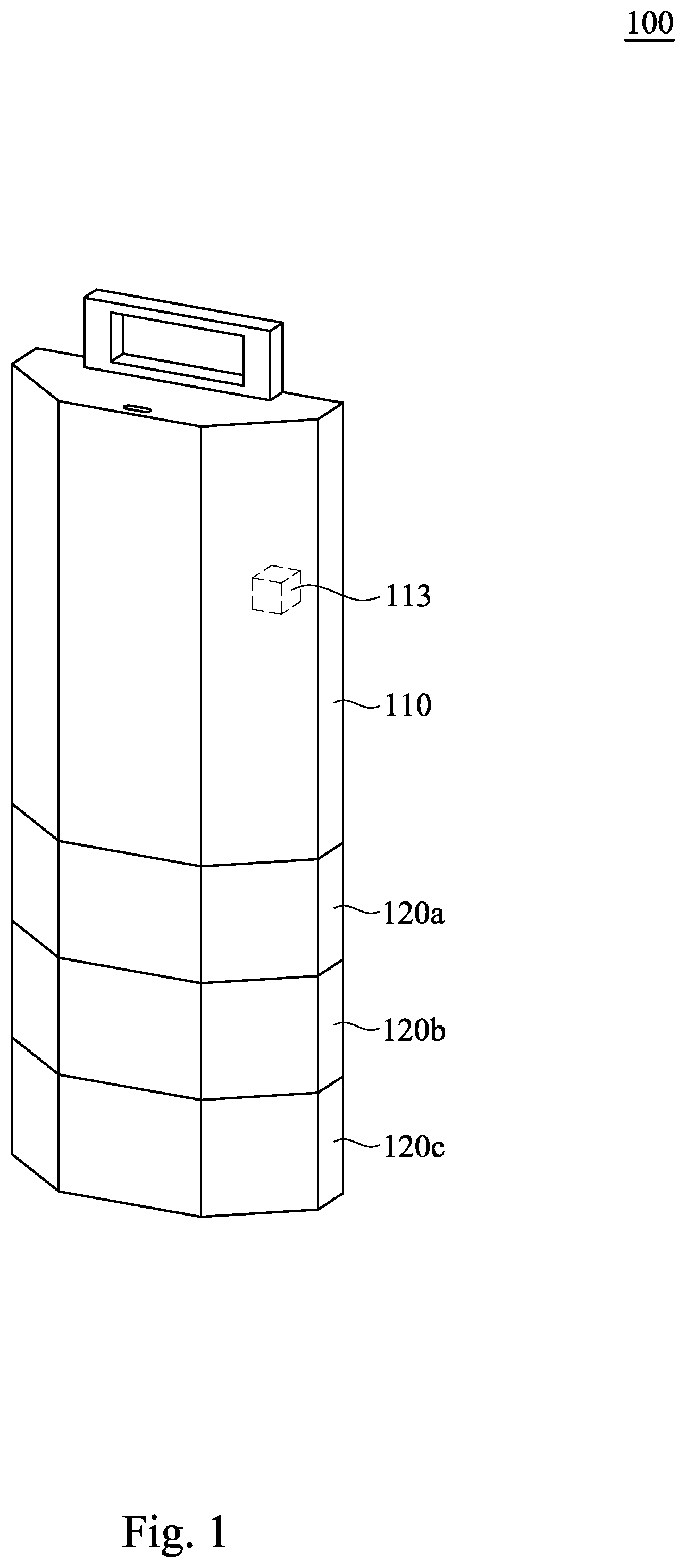
Reference is made to . is a schematic diagram illustrating a modular Internet of Things (IoT) sensor system 100 according to some embodiments of the present disclosure. In some embodiments of the present disclosure, the modular IoT sensor system 100 includes a network module 110 and expanded sensor modules 120 a ˜ 120 c.
The expanded sensor modules 120 a ˜ 120 c are configured to detect information in an environment to generate sensing data, the said information can be physical quantity (such as, light intensity, temperature, humidity, pressure or other physical properties) or chemical composition (such as, carbon monoxide, sulfur dioxide, hydrogen sulfide, ammonia or other chemical compositions). And, the expanded sensor modules 120 a ˜ 120 c transmit the sensing data to the network module 110 .
The network module 110 is configured to collect the sensing data generated by the expanded sensor modules 120 a ˜ 120 c by detecting the information in the environment, so as to process the sensing data and send the sensing data to the cloud database. In some embodiments, the network module 110 includes an integration of one or more processing circuit (such as, central processing unit (CPU), graphic processing unit (GPU), microcontroller or other circuit capable with data processing/calculating functions) and wireless communication circuit (such as, Wi-Fi communication, Internet of Things communication circuit, LTE-machine to machine communication circuit, long range communication circuit, narrow board Internet of Things communication circuit, communication circuit which supports fourth/fifth-generation technology standard, Bluetooth communication circuit, Zigbee communication circuit or other communication circuit). The said processing circuit and the said communication circuit can operate with appropriate software/firmware to collect the sensing data, generated by detecting the information in the environment by the expanded sensor modules 120 a ˜ 120 c , and to convert the sensing data into a data format for wireless communication transmission, so as to send the sensing data to the cloud database through the wireless communication.
In some embodiments, the network module 110 can further include an energy storage component 113 . Specifically, the energy storage component 113 can be implemented by a secondary battery, so as to store electrical energy and provide the power to the inner circuit (such as, the aforesaid processing circuit and the said communication circuit) of the network module 110 and the expanded sensor module 120 a ˜ 120 c.
Structurally, the expanded sensor modules 120 a ˜ 120 c can be stacked and coupled to the network module 110 and/or can be stacked and coupled to each other like building blocks. The connection of the said stacking and coupling can be detachably stacked connection, to reduce difficulties of replacing the sensing devices into the modular IoT sensor system 100 for user. As such, user can conveniently replace the expanded sensor module 120 a ˜ 120 c or add addition expanded sensor modules into the modular IoT sensor system 100 according to the desired detection information in the environment at the location.
Although the embodiments in illustrates multiple expanded sensor modules 120 a ˜ 120 c , the expanded sensor module(s) included in the modular IoT sensor system 100 can be configured according to the requirement of the detection place, and therefore the number of the expanded sensor module(s) included in the modular IoT sensor system 100 can be any positive integer, the present disclosure is not limited thereto.
Reference is made to and . is a schematic diagram illustrating a part drawing of a modular IoT sensor system 100 according to some embodiments of the present disclosure. As shown in , the network module 110 includes female connectors 111 and 112 are respectively disposed in opposite sides of a main body of the network module 110 . The female connectors 111 and 112 are respectively disposed in connection surfaces US 1 and DS 1 of the network module 110 . The connection surfaces US 1 is an upper surface of a shell of the network module 110 , and the connection surfaces DS 1 is a bottom surface of the shell of the network module 110 . In some embodiments, the aforesaid shell of the network module 110 is a hollow building block.
The connection surfaces US 1 and DS 1 of the network module 110 are linear symmetric in shape (such as, triangle, quadrangle, pentagon, hexagon or octagon in shape), and have symmetrical axes A 11 , A 12 , respectively. The symmetrical axis A 11 of the connection surface US 1 pass through the female connector 111 . The symmetrical axis A 12 of the connection surface DS 1 pass through the female connector 112 . In certain case, even if the connection surfaces US 1 and/or DS 1 of the network module 110 are not staked with the other module, upper side and bottom side of the main body of the network module 110 including the female connectors 111 and 112 instead of any protruding connector, in order to increase the utilization of the connection surface US 1 of the network module 110 and to increase the stability of the modular IoT sensor 100 . Therefore, when the expanded sensor module 120 a is directly combined to the network module 110 by connecting the male connector 121 a to the female connector 112 , the entire mechanical structure is better and the expanded sensor module 120 a is hard to fall off the network module 110 causing by the unbalance force.
The expanded sensor module 120 a includes a male connector 121 a and a female connector 122 a disposed in the opposite sides of a main body of the expanded sensor module 120 a . The male connector 121 a is disposed in the connection surface US 2 a of the expanded sensor module 120 a , and the male connector 121 a is configured to detachably connect to the female connector 112 of the network module 110 . The female connector 122 a is disposed in the connection surface DS 2 a of the expanded sensor module 120 a . The connection surfaces US 2 a and DS 2 a are in the same shape and are parallel to each other. The connection surfaces US 2 a is an upper surface of a shell of the expanded sensor module 120 a , and the connection surfaces DS 2 a is a bottom surface of the shell of the expanded sensor module 120 a . In some embodiments, the aforesaid shell of the expanded sensor module 120 a is a hollow building block.
In some embodiments, the connection surfaces US 2 a and DS 2 a are in symmetric shapes (such as, triangle, quadrangle, pentagon, hexagon or octagon in symmetric) in respect to the symmetrical axis A 2 a , and the configurations of the male connector 121 a and the female connector 122 a are on a basis of symmetrical axis A 2 a . In certain case, even if the bottom side of the expanded sensor module 120 a is not staked with the other module, the connection surface DS 2 a of the expanded sensor module 120 a including the female connector 122 a instead of any protruding connector, in order to increase the stability of the modular IoT sensor 100 .
The expanded sensor module 120 b includes a male connector 121 b respectively disposed in connection surfaces US 2 b and DS 2 b of the expanded sensor module 120 b , in which the connection surfaces US 2 b and DS 2 b are in the same shape and are parallel to each other. The connection surfaces US 2 b is an upper surface of a shell of the expanded sensor module 120 b , and the connection surfaces DS 2 b is a bottom surface of the shell of the expanded sensor module 120 b . In some embodiments, the aforesaid shell of the expanded sensor module 120 b is a hollow building block. The expanded sensor module 120 c includes a male connector 121 c respectively disposed in connection surfaces US 2 c and DS 2 c of the expanded sensor module 120 c , in which the connection surfaces US 2 c and DS 2 c are in the same shape and are parallel to each other. The connection surfaces US 2 b is an upper surface of a shell of the expanded sensor module 120 b , and the connection surfaces DS 2 b is a bottom surface of the shell of the expanded sensor module 120 b . In some embodiments, the aforesaid shell of the expanded sensor module 120 b is a hollow building block.
In some embodiments, the male connector 121 b of the expanded sensor module 120 b is configured to detachably connect to the female connector 122 a of the expanded sensor module 120 a . The male connector 121 c of the expanded sensor module 120 c is configured to detachably connect to the female connector 122 b of the expanded sensor module 120 b.
The shape and the structure of the expanded sensor modules 120 b and 120 c are similar with the expanded sensor module 120 a . And, the configurations of the male connector 121 b and the female connector 122 b included in the expanded sensor module 120 b and the male connector 121 c and the female connector 122 c included in the expanded sensor module 120 c are similar with the male connector 121 a and the female connector 122 a included in the expanded sensor module 120 a , and the description is omitted herein.
In some embodiments, the connection surface DS 12 of the network module 110 and the connection surfaces US 2 a ˜US 2 c and DS 2 a ˜DS 2 c of the expanded sensor modules 120 a ˜ 120 c are almost the same in shape and area, so that the network module 110 and the expanded sensor module 120 a ˜ 120 c are capable for staking together like building blocks.
To be noted that, the female connector 112 included in the network module 110 and the male connectors 121 a ˜ 121 c and the female connectors 122 a ˜ 122 c included in the expanded sensor module 120 a ˜ 120 c are in shape and size confirming the universal serial bus type C specification. The pin definitions of the female connector 112 included in the network module 110 and the male connectors 121 a ˜ 121 c and the female connectors 122 a ˜ 122 c included in the expanded sensor modules 120 a ˜ 120 c are complied with the first pin definition PD 1 which redefines a portion of pins in the universal serial bus type C specification. The configuration of the first pin definition PD 1 will be described in detailed in the following embodiments.
Reference is made to to . is a schematic diagram illustrating a male connector 121 connected through internal connection lines INLS 2 to a female connector 122 of an expanded sensor module 120 according to some embodiments of the present disclosure. The connection relationships between the male connectors 121 a ˜ 121 c and the corresponding female connectors 122 a ˜ 122 c included in the expanded sensor modules 120 a ˜ 120 c in the embodiments of and are similar with/equal to the connection relationship between the male connector 121 and the female connector 122 included in the expanded sensor module 120 in the embodiments of . In some embodiments, the internal connection lines INLS 2 of the expanded sensor module 120 corresponding to the internal connection lines included in each of the expanded sensor modules 120 a and 120 b.
As shown in , the expanded sensor module 120 includes a male connector 121 , a female connector 122 and multiple internal connection lines INLS 2 . Each of the pins A 1 ˜A 12 and B 1 ˜B 12 of the male connector 121 has a one-to-one correspondence with a corresponding one of the pins A 1 ˜A 12 and B 1 ˜B 12 of the male connector 121 . Each of the pins A 1 ˜A 12 and B 1 ˜B 12 of the male connector 121 is one-to-one connected to a corresponding one of the pins A 1 ˜A 12 and B 1 ˜B 12 of the male connector 121 through the internal connection lines INLS 2 . Specifically, the pin A 1 of the male connector 121 is connected to the pin A 1 of the female connector 122 through an internal connection line. The pin A 2 of the male connector 121 is connected to the pin A 2 of the female connector 122 through another internal connection line. The pin A 3 of the male connector 121 is connected to the pin A 3 of the female connector 122 through another internal connection line, and so on.
Each of the male connector 121 and the female connector 122 includes a power pin set which includes ground pins GND and bus power pins VBUS. The ground pins GND and bus power pins VBUS are respectively configured in the pins A 1 , A 4 , A 9 , A 12 , B 1 , B 4 , B 9 , B 12 included in each of the male connector 121 and the female connector 122 . The said power pin set confirms the universal serial bus type C specification. The other pins of the male connector 121 and the female connector 122 are redefined to be different from the universal serial bus type C specification.
Reference is made to to A and B . A and B are schematic diagrams illustrating a first pin definition PD 1 according to some embodiments of the present disclosure. As shown in A , the first pin definition PD 1 includes the power pin set, the shared pin sets SPG 1 ˜SPG 3 and the non-shared pin sets PDG and PAG.
The power pin set is configured to provide power and grounding path. Each of the shared pin sets SPG 1 ˜SPG 3 is capable for transmitting sensing data generated from various sensors or multiple modules through a shared portion of internal connection lines. In other words, each of the shared pin sets SPG 1 ˜SPG 3 is capable for transmitting sensing data confirming the same data transmission protocol generated from various sensors or multiple modules through the same internal connection lines. Each of the non-shared pin sets PDG and PAG is capable for transmitting sensing data generated from a single/dedicated sensor through a non-shared portion of internal connection lines.
As shown in B , the power pin set includes the ground pins GND and bus power pins GND which are respectively configured in pins A 1 , A 4 , A 9 , A 12 , B 1 , B 4 , B 9 and B 12 . The aforesaid power pin set is equal to/similar with the power pin set in the embodiments of , and the description is omitted herein.
The shared pin set SPG 1 includes a serial clock pin ISC_CLK and a serial data pin ISC_SDA. As such, the sensor including the I2C pins in the modular IoT sensor 100 can transmit the sensing data conforming to the I2C protocol by the shared pin set SPG 1 .
The shared pin set SPG 2 includes a serial clock pin SPI_CLK, a master output pin SPI_MOSI, a salve output pin SPI_MISO and a slave select pin SPI_CLI. As such, the sensor including the SPI pins in the modular IoT sensor 100 can transmit the sensing data conforming to the SPI protocol by the shared pin set SPG 2 .
The shared pin set SPG 3 includes the data send/receive pin UART+ and the data receive/send pin UART−. As such, the sensor including the UART pins in the modular IoT sensor 100 can transmit the sensing data conforming to the RS485 specification by the shared pin set SPG 3 .
In some other embodiments, the shared pin set SPG 3 can be configured to transmit the electrical signal confirms the RS232 specification, which is not intended to limit the present disclosure.
The non-shared pin set PDG includes the digital data input/output pins DIN/DOUT 1 ˜DIN/DOUT 4 and the digital data input/output pin DIN/DOUT 1 ˜DIN/DOUT 4 which are to transmit the sensing data generated form the single/dedicated sensor included in the modular IoT sensor 100 . In some embodiments, the non-shared pin set PDG can be considered as non-shared digital data pin set.
The non-shared pin set PAG includes the analog data input pins AIN 1 ˜AIN 3 and the analog data output pin AOUT, the corresponding one of which is to transmit the sensing data generated from a single/dedicated sensor/module included in the modular IoT sensor 100 . In some embodiments, the non-shared pin set PAG can be considered as non-shared analog data pin set.
To integrate the aforementioned signal transmission protocol in various type, in the modular IoT sensor 100 , pin definitions of the female connector 112 disposed in the bottom surface DS 1 of the network module 110 and the male connectors 121 a ˜ 121 c and the female connectors 122 a ˜ 122 c respectively disposed in the expanded sensor modules 120 a ˜ 120 c are implemented by the first pin definition PD 1 . When the expanded sensor module 120 a ˜ 120 c and the network module 110 are stacked and mechanically connected together, the expanded sensor module 120 a ˜ 120 c are electrically and connected in series by the corresponding male connectors 121 a ˜ 121 c and female connectors 122 a ˜ 122 c , and the male connector of first one of the expanded sensor module 120 a ˜ 120 c is electrically connected to the female connector 112 of the network module 110 .
As such, the network module 110 is capable for receiving electrical signals in varies type through the male connectors 121 a ˜ 121 c and the female connectors 122 a ˜ 122 c of the expanded sensor modules 120 a ˜ 120 c , in order to integrate the different data transmission protocols of sensors in varies types to the modular IoT sensor 100 .
Although the embodiments in A and B illustrates multiple shared pin sets SPG 1 ˜SPG 3 and multiple non-shared pin sets PDG and PAG, the shared pin set and the non-shared pin set in the first pin definition PD 1 can be configured according to the requirement for the whole system, so that the number of the shared pin set and/or the number of the non-shared pin set in the first pin definition PD 1 can be any positive integer, the present disclosure is not limited thereto.
To better understanding, reference is made to to . to are schematic diagrams illustrating transmission of sensing data of sensors 123 a ˜ 123 c through a male connectors 121 a ˜ 121 c and a female connectors 122 a ˜ 122 c of expanded sensor modules 120 a ˜ 120 c under a specification of the first pin definition PD 1 according to some embodiments of the present disclosure.
To be noted that, each of the expanded sensor modules 120 a ˜ 120 c includes internal connection lines. The connection relationship of the internal connection lines in each of the internal connection lines corresponds to the connection relationship of the internal connection lines INLS 2 connected between the male connector 121 and the female connector 122 of the expanded sensor module 120 in the . Specifically, internal connection lines included in the expanded sensor modules 120 a connect pins of the male connector 121 a to pins of the female connector 122 a on a basis of a one-to-one correspondence between each pins of the male connector 121 a and each pins of the female connector 122 a . Internal connection lines included in the expanded sensor modules 120 b connect pins of the male connector 121 b to pins of the female connector 122 b on a basis of a one-to-one correspondence between each pin of the male connector 121 b and a corresponding pin of the female connector 122 b . Internal connection lines included in the expanded sensor modules 120 c connect pins of the male connector 121 c to pins of the female connector 122 c on a basis of a one-to-one correspondence between each pin of the male connector 121 c and a corresponding pin of the female connector 122 c.
To clarity, embodiments of to only show a portion of the internal connection lines INLS 2 . In some embodiments, each pin of the male connectors 121 a is one-to-one connected to a corresponding pin of the male connectors 121 a . Each pin of the male connectors 121 b is one-to-one connected to a corresponding pin of the male connectors 121 b . Each pin of the male connectors 121 c is one-to-one connected to a corresponding pin of the male connectors 121 c.
As shown in , the expanded sensor module 120 a includes a male connector 121 a , a female connector 122 a and a sensor 123 a . The sensor 123 a is supposed to include I2C pins and analog data pin, the sensor 123 a is electrically coupled to internal connection lines INLS 2 a which are a portion of the internal connection lines INLS 2 . The internal connection lines INLS 2 connect the sensor 123 a to the power pin set (the ground pins GND and the bus power pins VBUS), the shared pin set SPG 1 (the serial clock pin ISC_CLK and the serial data pin ISC_SDA) and the analog input pin AIN included in the non-shared pin set PAG.
Therefore, the sensor 123 a of the expanded sensor module 120 a can receive the power supplied from the energy storage component 113 of the network module 110 by the power pin set of the male connector 121 a . The sensor 123 a of the expanded sensor module 120 a uses the electrical signals confirm I2C protocol for transmitting sensing data to the network module 110 by the shared pin set SPG 1 of the male connector 121 a . And, the sensor 123 a of the expanded sensor module 120 a can transmit the analog signal to through the analog input pin AIN of the male connector 121 a to the network module 110 .
As shown , the expanded sensor module 120 b includes a male connector 121 b , a female connector 122 b and a sensor 123 b . The sensor 123 b is supposed to include SPI pins and digital data pins. The sensor 123 b is electrically coupled to internal connection lines INLS 2 b which are a portion of the internal connection lines INLS 2 . The internal connection lines INLS 2 b connect the sensor 123 b to the power pin set (the ground pins GND and bus power pins VBUS), the shared pin set SPG 2 (the serial clock pin SPI_CLK, the master output pin SPI_MOSI, the salve output pin SPI_MISO and the slave select pin SPI_CLI) and the digital data input/output pin DIN 1 included in the non-shared pin set PDG.
Therefore, the sensor 123 b of the expanded sensor module 123 b can receive the power supplied from the energy storage component 113 of the network module 110 by the power set of the male connector 121 b . The sensor 123 b of the expanded sensor module 123 b uses electrical signals confirm the SPI protocol for transmitting sensing data to the network module 110 by the shared pin set SPG 2 included in each of the male connector 121 b of the expanded sensor module 120 b and the female connector 122 a and the male connector 121 a of the expanded sensor module 120 a . And, the sensor 123 b of the expanded sensor module 123 b can transmit the digital signals to the network module 110 through the digital output/input pin DIN/DOUT 1 included in each of the male connector 121 b of the expanded sensor module 120 b and the female connector 122 a and the male connector 121 a of the expanded sensor module 120 a.
As shown in , the expanded sensor module 120 c includes a male connector 121 c , a female connector 122 c and a sensor 123 c . The sensor 123 c is supposed to include UART pins. The sensor 123 c is electrically coupled to internal connection lines INLS 2 c which are a portion of the internal connection lines INLS 2 . The internal connection lines INLS 2 connect the sensor 123 c to the power pin set (the ground pins GND and the bus power pins VBUS) and the shared pin set SPG 3 (the data send/receive pin UART+, and the data receive/send pin UART−).
Therefore, the sensor 123 c of the expanded sensor module 120 c can receive the power supplied from the energy storage component 113 of the network module 110 through the power pin set of the male connector 121 c . The sensor 123 c of the expanded sensor module 120 c uses electrical signals which confirm RS485 protocol for transmitting sensing data to the network module 110 through the shared pin set SPG 3 included in each of the female connector 122 c of the expanded sensor module 120 c , the female connector 122 b and the male connector 121 b of the expanded sensor module 120 b , the female connector 122 a and the male connector 121 a of the expanded sensor module 120 a to the network module 110 .
In the aforementioned embodiments, each of the sensors 123 a ˜ 123 c can be implemented by an image sensor, a temperature sensor, a humidity sensor, a gas detection sensor, a distance sensor, a pressure sensor, a human body infrared sensor, an acceleration sensor, a sound sensor, a soil moisture sensor, a gas sensor, a displacement sensor or the other sensor, which is not intended to limit the present disclosure.
In some embodiments, the expanded sensor modules 120 a ˜ 120 c can further include one or more switches, such as, relay (not shown), for activing the corresponding device (such as, the said sensor in the present disclosure). In actual application, user can uses the mobile phone (such as, the smart phone) to transmit the cloud control signal to the network module 110 , and the network module 110 can commute the said switch to active the corresponding device.
In some embodiments, the configuration of the first pin definition PD 1 has a rotational symmetry. That is, the configuration of pins A 1 ˜A 12 of the first pin definition PD 1 and the configuration of pins B 1 ˜B 12 of the first pin definition PD 1 are symmetry, and the expanded sensor modules 123 a ˜ 123 c and the network module 110 are electrically and mechanically connected and are relatively rotatable.
Reference is made to . is a schematic diagram illustrating a modular IoT sensor 100 for Internet of things according to some embodiments of the present disclosure. In the embodiments of , the modular IoT sensor 100 further includes a power module 130 .
The power module 130 is detachably coupled to the network module 110 , the power module 130 is configured to obtain energy from the environment and convert the energy to the power. The power module 130 provide the power to the network module 110 to store/utilization, so as to provide the power generated by the power module 130 to the expanded sensor module 120 a ˜ 120 c from the network module 110 .
The power module 130 includes the female connector 131 and the male connector 132 disposed in the opposite sides of a main body of the power module 130 , in which the female connector 131 is disposed in a connection surface US 3 of a shell of the power module 130 , and the male connector 132 is disposed in a connection surface DS 3 of the shell of power module 130 . The connection surfaces US 3 is an upper surface of a shell of the power module 130 , and the connection surfaces DS 3 is a bottom surface of the shell of the power module 130 . In some embodiments, the aforesaid shell of the power module 130 is a hollow building block. The connection surfaces US 3 and DS 3 of the power module 130 are in linear symmetric in shape (such as, triangle, quadrangle, pentagon, hexagon or octagon in shape), and have symmetrical axes A 31 , A 31 , respectively. The symmetrical axis A 31 passes through the female connector 131 . The symmetrical axis A 32 passes through the male connector 132 .
The female connector 131 and the male connector 132 of the power module 130 and the female connector 111 of the network module 110 are in shape and size which are confirm to the universal serial bus type C specification.
To be noted, pin definitions of the female connector 131 and the male connector 132 of the power module 130 and the female connector 111 of the network module 110 are complied with a second pin definition PD 2 which is to redefine a portion of pins in the universal serial bus type C specification, and the second pin definition PD 2 is different from the aforesaid first pin definition PD 1 . The second pin definition PD 2 will be described in detailed in the following embodiments.
Reference is made to to B . A and B are schematic diagrams illustrating a second pin definition PD 2 according to some embodiments of the present disclosure. As shown in A , the second pin definition PD 2 includes a power pin set, shared pin sets SPG 31 ˜SPG 32 , non-shared pin sets PDG and PAG and a power interface pin set PCIG.
The power pin set is configured to provide power and grounding path. Each of the shared pin sets SPG 31 ˜SPG 32 is capable for transmitting sensing data generated from various sensors or multiple modules through a shared portion of internal connected lines. In other words, each of the shared pin sets SPG 31 ˜SPG 32 is capable for transmitting sensing data confirming the same data transmission protocol generated from various sensors or multiple modules through the same internal connection lines. Each of the non-shared pin sets PDG and PAG is capable for transmitting sensing data generated from a single/dedicated sensor/module by a non-shared portion of the internal connected lines.
Although the embodiments of A illustrate multiple shared pin sets SPG 31 ˜SPG 32 and non-shared pin sets PDG and PAG, the shared pin set and the non-shared pin set included in the second pin definition PD 2 can be configured on a basis of the requirement for entire system, so the number of the shared pin set and/or the number of the non-shared pin set in the second pin definition PD 2 can be any positive integer, the present disclosure is not limited thereto.
As shown in B , the power pin set include the ground pins GND and bus power pins VBUS which are disposed in pins A 1 , A 4 , A 9 , A 12 , B 1 , B 4 , B 9 and B 12 , respectively, the said power pin set corresponding to the power pin set in the embodiment of , and the description is omitted here.
The shared pin sets SPG 31 and SPG 32 include the data send/receive pins UART 1 + and UART 2 + and the data receive/send pins UART 1 − and UART 2 −. As such, device(s) staked up on the upper side of the network module 110 and including UART pins can use the electrical signal confirm UART protocol for transmitting data through the shared pin set SPG 31 or SPG 32 .
The non-shared pin set PDG includes digital data input/output pins DIN/DOUT 1 ˜DIN/DOUT 4 which are configured to provide data transmission path for the dedicated sensor/module stacked on the upper side of the network module 110 . In some embodiments, the non-shared pin set PDG can be considered as non-shared digital data pin set.
The non-shared pin set PAG includes analog data input pins AIN 1 ˜AIN 3 and an analog data output pin AOUT. At least one of the analog data input pins AIN 1 ˜AIN 3 and the analog data output pin AOUT is configured to transmit data generated from a single/dedicated sensor/device stacked on the upper side of the network module 110 . In some embodiments, the non-shared pin set PAG can be considered as non-shared analog data pin set.
The power interface pin set PCIG includes a positive pin of input voltage VIN+, a negative pin of input voltage VIN−, a battery voltage pin VBAT and a reference voltage pin VS which are configured in pins A 10 , A 11 , B 2 and B 3 included in each of the female connector 131 and the male connector 132 .
In the modular IoT sensor 100 , pin definitions of the female connector 111 disposed in the connection surface US 1 of the network module 110 , the female connector 131 and the male connector 132 respectively disposed in the connection surfaces US 3 and DS 3 of the power module 130 are implemented by the second pin definition PD 2 .
Reference is made to . is a schematic diagram illustrating transmission of power through female connector 131 and male connector 132 of the renewable emerge charger 133 in the power module 130 according to some embodiments of the present disclosure.
As shown in , the power module 130 includes a female connector 131 , a male connector 132 , a renewable energy charger 133 , power path switches 135 and 137 and power transmission controllers 134 and 136 .
The power module 130 includes internal connection lines INLS 3 . The internal connection lines INLS 3 connect the power path switches 135 and 137 and power transmission controllers 134 and 136 to the power pin set and the power interface pin set PCIG included in each of the female connector 131 and the male connector 132 .
The power transmission controllers 134 and 136 can control the power path switch 135 and/or the power path switch 137 to turn on or turn off the current paths between the renewable energy charger 133 to the power pin set (such as, the bus power pins VBUS included in each of the female connector 131 and the male connector 132 ). As such, when the male connector 132 of the power module 130 is connected to the female connector 111 of the network module 110 , the network module 110 can receive the power generated by the renewable energy charger 133 from the female connector 111 .
In some embodiments, the renewable energy charger 133 can be implemented by a thermoelectric power generation charger, a solar power generation charger, a microwave power generation charger, a wind power generation charger, a hydroelectric power generation charger or the other natural energy charger, which is not intended to limit the present disclosure.
Reference is made to . is a schematic diagram illustrating a modular IoT sensor 100 for Internet of things according to some embodiments of the present disclosure. In some embodiments, the modular IoT sensor 100 further includes transmission lines 140 a and 140 b . The male connector 132 of the power module 130 is electrically coupled to the female connector 111 of the network module 110 by the transmission line 140 b . The female connector 112 of the network module 110 is electrically connected to the male connector 121 a of the expanded sensor module 120 a by the transmission line 140 a.
In certain cases, user can adjust the length of the transmission line 140 b to control the separation distance between the network module 110 and the power module 130 , such that the network module 110 and the power module 130 can be placed at the appropriate places, respectively, and maintain the connection between the network module 110 and the power module 130 . That is, the network module 110 can be placed at a place with good communication signal. Therefore, the sensing data can be reliably sent to the cloud by placing the network module 110 at an appropriate place, and the electrical power can be reliably generated by placing the network module 110 at the other place. And, user can also adjust the length of the transmission line 140 a to control the separation distance between the expanded sensor modules 120 a ˜ 120 c to move the expanded sensor module 120 a ˜ 120 c to the appropriate places.
Summary, the expanded sensor modules 120 a ˜ 120 c and the power module 130 of the modular IoT sensor 100 are staked to the bottom side and the upper side of the network module 110 like building blocks. The replacement of the expanded sensor modules 120 a ˜ 120 c and/or the addition of the expanded sensor module is convenient for user, and the expanded sensor modules 120 a ˜ 120 c and the power module 130 included in the modular IoT sensor 100 can be configured on the basis of the best power generation manner and the requirement of sensing data at the detection place. And, the sensing data of the expanded sensor modules 120 a ˜ 120 c can be transmitted back to the network module 110 to send out the sensing data by wireless communication.
Although specific embodiments of the disclosure have been disclosed with reference to the above embodiments, these embodiments are not intended to limit the disclosure. Various alterations and modifications may be performed on the disclosure by those of ordinary skills in the art without departing from the principle and spirit of the disclosure. Thus, the protective scope of the disclosure shall be defined by the appended claims.
Figures (11)
Citations
This patent cites (6)
- US9577392
- US9949047
- US10499123
- US2015/0356051
- US2017/0316683
- USM633816