Abstract
The present invention discloses an inductor apparatus. Each of a first section of a second and a fourth quadrant loops are bridged to a first section of a former quadrant loop and are bridged to a third section to a second section of a diagonal quadrant loop. Each of a second section of the second and the fourth quadrant loops are coupled to a third section of the diagonal quadrant loop, and to the second section of a former quadrant loop. A first section of a third quadrant loop is coupled to a first section of the fourth quadrant loop, and to a third section of the first quadrant loop. The second section of the third quadrant loop is coupled to a second section of the fourth quadrant loop and to a third section of the third quadrant loop, and to a third section of the first quadrant loop.
Claims (10)
1. An inductor apparatus comprising: four coil loops arranged in an order of a clockwise manner and comprising: a first quadrant coil loop comprising a first section, a second section and a third section, wherein the first section thereof is directly coupled to a first I/O terminal, and the second section thereof is directly coupled to a second I/O terminal; a second quadrant coil loop and a fourth quadrant coil loop each comprising a first section, a second section and a third section, wherein the first section thereof is centrally bridged over a central area of the four coil loops to the first section of a former quadrant coil loop, and the first section thereof is also laterally bridged over the second section thereof to the third section thereof such that the third section thereof is further directly coupled to the second section of a diagonal quadrant coil loop through the central area, and the second section thereof is directly coupled to the third section of the diagonal quadrant coil loop, and second section thereof is also directly coupled to the second section of the former quadrant coil loop through the central area; and a third quadrant coil loop comprising a first section, a second section and a third section, wherein the first section thereof is centrally bridged over the central area to the first section of the fourth quadrant coil loop and the first section thereof is also centrally bridged over the central area to the third section of the first quadrant coil loop, the second section thereof is directly coupled to the second section of the fourth quadrant coil loop through the central area and the second section thereof is also laterally bridged over the first section thereof to the third section thereof such that the third section thereof is further centrally bridged over the central area to the third section of the first quadrant coil loop; and a plurality of centrally bridging line sections and a plurality of laterally bridging line sections configured to perform central bridging and lateral bridging.
10. An inductor apparatus comprising: four coil loops arranged in an order of a clockwise manner and comprising: a first quadrant coil loop comprising a first section and a second section, wherein the first section is directly coupled to a first I/O terminal and the second section is directly coupled to a second I/O terminal; a second quadrant coil loop comprising a first section directly coupled to the second section of the first quadrant coil loop through a central area of the four coil loops; a third quadrant coil loop comprising a first section centrally bridged over the central area to the first section of the first quadrant coil loop; and a fourth quadrant coil loop comprising a first section directly coupled to the first section of the second quadrant coil loop through central area and centrally bridged over the central area to the first section of the third quadrant coil loop; and a plurality of centrally bridging line sections configured to perform central coupling.
Show 8 dependent claims
2. The inductor apparatus of claim 1 , wherein a total number of the centrally bridging line sections and the laterally bridging line sections is 7.
3. The inductor apparatus of claim 1 , wherein the first section, the second section and at least part of the third section of each of the first quadrant coil loop, the second quadrant coil loop, the third quadrant coil loop and the fourth quadrant coil loop form two outermost circle structures.
4. The inductor apparatus of claim 3 , wherein the third section of each of the second quadrant coil loop and fourth quadrant coil loop is laterally bridged to the first section thereof from a central region of each of the second quadrant coil loop and the fourth quadrant coil loop, winds to surround the central region to form at least one circle of an inner circle structure and a part of the two outermost circle structures to be further directly coupled to the second section of the diagonal quadrant coil loop.
5. The inductor apparatus of claim 3 , wherein the third section of the first quadrant coil loop is centrally bridged over the central area to the first section of the third quadrant coil loop from a central region of the first quadrant coil loop, winds to surround the central region to form at least one circle of an inner circle structure and a part of the two outermost circle structures to be further centrally bridged over the central area to the third section of the third quadrant coil loop; the third section of the third quadrant coil loop is centrally bridged over the central area to the third section of the first quadrant coil loop from a central region of the third quadrant coil loop, winds to surround the central region to form at least one circle of an inner circle structure and a part of the two outermost circle structures to be further laterally bridged to the second section of the third quadrant coil loop.
6. The inductor apparatus of claim 1 , wherein the third section of the first quadrant coil loop comprises a central tap.
7. The inductor apparatus of claim 1 , wherein a current flowing direction of the first quadrant coil loop and the third quadrant coil loop is a first direction and the current flowing direction of the second quadrant coil loop and the fourth quadrant coil loop is a second direction, wherein one of the first direction and the second direction is a clockwise direction and the other one of the first direction and the second direction is a counterclockwise direction.
8. The inductor apparatus of claim 7 , wherein a magnetic field direction of each of the first quadrant coil loop, the second quadrant coil loop, the third quadrant coil loop and the fourth quadrant coil loop is determined by the current flowing direction thereof.
9. The inductor apparatus of claim 1 , wherein an impedance of each of the centrally bridging line sections and the laterally bridging line sections is larger than the impedance of the first section, the second section and the third section of each of the first quadrant coil loop, the second quadrant coil loop, the third quadrant coil loop and the fourth quadrant coil loop.
Full Description
Show full text →
BACKGROUND OF THE INVENTION
1. Field of the Invention
The present invention relates to an inductor apparatus.
2. Description of Related Art
Inductors are electronic devices that operate based on electromagnetic induction. When a current flows through a wire, an electromagnetic field is generated around the wire. The electromagnetic field generated by the wire may induct other wires within the electromagnetic field. Usually, the wire is winded to form a coil to enhance the magnetic field inside of the coil to form the inductor apparatus in circuits.
However, the formation of the coil may affect the complexity and the efficiency of the inductor apparatus. The material of line sections used to perform bridging is different from the material of the wires and has higher impedance. When the wiring method of the coil is not designed well, the number of the line sections used to perform bridging may increase along with the increase of the number of the coil loops. Not only the complexity of the wiring of the inductor apparatus increases, the increase of the impedance also impacts the efficiency thereof.
SUMMARY OF THE INVENTION
In consideration of the problem of the prior art, an object of the present invention is to provide a signal enhancement relay apparatus and a signal enhancement relay method.
The present invention discloses an inductor apparatus that includes four coil loops, a plurality of centrally bridging line sections and a plurality of laterally bridging line sections. The four coil loops are arranged in an order of a clockwise manner and includes a first quadrant coil loop, a second quadrant coil loop, a third quadrant coil loop and a fourth quadrant coil loop. The first quadrant coil loop includes a first section, a second section and a third section, wherein the first section thereof is directly coupled to a first I/O terminal, and the second section thereof is directly coupled to a second I/O terminal Each of the second quadrant coil loop and the fourth quadrant coil loop includes a first section, a second section and a third section, wherein the first section thereof is centrally bridged over a central area of the four coil loops to the first section of a former quadrant coil loop, and the first section thereof is also laterally bridged over the second section to the third section thereof such that the third section thereof is further directly coupled to the second section of a diagonal quadrant coil loop through the central area, and the second section thereof is directly coupled to the third section of the diagonal quadrant coil loop, and the second section thereof is also directly coupled to the second section of the former quadrant coil loop through the central area. The third quadrant coil loop includes a first section, a second section and a third section, wherein the first section thereof is centrally bridged over the central area to the first section of the fourth quadrant coil loop and the first section thereof is also centrally bridged over the central area to the third section of the first quadrant coil loop, the second section thereof is directly coupled to the second section of the fourth quadrant coil loop through the central area and the second section thereof is also laterally bridged over the first section thereof to the third section of the third quadrant coil loop such that the third section of the third quadrant coil loop is further centrally bridged over the central area to the third section of the first quadrant coil loop. The centrally bridging line sections and the laterally bridging line sections are configured to perform central coupling and lateral bridging.
The present invention also discloses an inductor apparatus that includes four coil loops and a plurality of centrally bridging line sections. The four coil loops are arranged in an order of a clockwise manner and includes a first quadrant coil loop, a second quadrant coil loop, a third quadrant coil loop and a fourth quadrant coil loop. The first quadrant coil loop includes a first section and a second section, wherein the first section thereof is directly coupled to a first I/O terminal and the second section thereof is directly coupled to a second I/O terminal. The second quadrant coil loop includes a first section directly coupled to the second section of the first quadrant coil loop over a central area of the four coil loops. The third quadrant coil loop includes a first section centrally bridged to the first section of the first quadrant coil loop over the central area. The fourth quadrant coil loop includes a first section directly coupled to the first section of the second quadrant coil loop through central area and centrally bridged to the first section of the third quadrant coil loop over the central area. The centrally bridging line sections are configured to perform central coupling.
These and other objectives of the present invention will no doubt become obvious to those of ordinary skill in the art after reading the following detailed description of the preferred embodiments that are illustrated in the various figures and drawings.
BRIEF DESCRIPTION OF THE DRAWINGS
illustrates a circuit diagram of an inductor apparatus according to an embodiment of the present invention.
illustrates a diagram of the current directions of the inductor apparatus under the condition that the first I/O terminal receives an input current according to an embodiment of the present invention.
illustrates a circuit diagram of an inductor apparatus according to another embodiment of the present invention.
illustrates a circuit diagram of an inductor apparatus according to yet another embodiment of the present invention.
DETAILED DESCRIPTION OF THE PREFERRED EMBODIMENTS
An aspect of the present invention is to provide an inductor apparatus to keep the number of the centrally bridging line sections and the laterally bridging line sections unchanged, by using the disposition method of the first section, the second section and the third section of each of the quadrant coil loops, without being affected by the number of the circles of each of the quadrant coil loops. The design of the inductor coil can be simplified and the efficiency thereof can be improved.
Reference is now made to . illustrates a diagram of an inductor apparatus 100 according to an embodiment of the present invention. The inductor apparatus includes four coil loops L 1 ˜L 4 , a plurality of centrally bridging line sections C 1 ˜C 4 and a plurality of laterally bridging line sections S 1 ˜S 3 .
The four coil loops L 1 ˜L 4 are arranged in an order of a clockwise manner and includes a first quadrant coil loop L 1 , a second quadrant coil loop L 2 , a third quadrant coil loop L 3 and a fourth quadrant coil loop L 4 . According to the arrangement relation of any one of the quadrant coil loop with the other three quadrant coil loops, each of the quadrant coil loops has a former quadrant coil loop, a latter quadrant coil loop and a diagonal quadrant coil loop disposed nearby.
Take the first quadrant coil loop L 1 as an example, the former quadrant coil loop is the fourth quadrant coil loop L 4 , the latter quadrant coil loop is the second quadrant coil loop L 2 and the diagonal quadrant coil loop is the third quadrant coil loop L 3 . Each of the rest of the three quadrant coil loops has an identical relation with other quadrant coil loops and is not further described herein.
Each of the coil loop L 1 ˜L 4 has three sections. More specifically, the first quadrant coil loop L 1 includes a first section L 11 , a second section L 12 and a third section L 13 . The second quadrant coil loop L 2 includes first section L 21 , a second section L 22 and a third section L 23 . The third quadrant coil loop L 3 includes a first section L 31 , a second section L 32 and a third section L 33 . The fourth quadrant coil loop L 4 includes a first section L 41 , a second section L 42 and a third section L 43 . The first sections L 11 , L 21 , L 31 and L 41 are illustrated as white blocks. The second sections L 12 , L 22 , L 32 and L 42 are illustrated as blocks with slash lines. The third sections L 13 , L 23 , L 33 and L 43 are illustrated as black blocks.
In the first quadrant coil loop L 1 , the first section L 11 thereof is directly coupled to a first I/O terminal IO 1 , and the second section L 12 thereof is directly coupled to a second I/O terminal IO 2 . In an embodiment, the third section L 13 includes a central tap CT.
In the second quadrant coil loop L 2 , the first section L 21 thereof is centrally bridged over a central area of the four coil loops L 1 ˜L 4 to the first section L 11 of the former quadrant coil loop (i.e., the first quadrant coil loop L 1 ), by using the centrally bridging line section C 1 . Further, the first section L 21 thereof is also laterally bridged over the second section L 22 thereof to the third section L 23 thereof by using the laterally bridging line section S 1 , such that the third section L 23 thereof is further directly coupled to the second section L 42 of the diagonal quadrant coil loop (i.e., the fourth quadrant coil loop L 4 ) through the central area. The second section L 22 thereof is directly coupled to the third section L 43 of the diagonal quadrant coil loop (i.e., the fourth quadrant coil loop L 4 ) through the central area, and the second section L 22 thereof is also directly coupled to the second section L 22 of the former quadrant coil loop (i.e., the first quadrant coil loop L 1 ) through the central area.
In the fourth quadrant coil loop L 4 , the first section L 41 thereof is centrally bridged over the central area to the first section L 31 of the former quadrant coil loop (i.e., the third quadrant coil loop L 3 ), by using the centrally bridging line section C 2 . Further, the first section L 41 thereof is also laterally bridged over the second section L 42 thereof to the third section L 43 thereof by using the laterally bridging line section S 2 , such that the third section L 43 thereof is further directly coupled to the second section L 22 of the diagonal quadrant coil loop (i.e., the second quadrant coil loop L 2 ) through the central area. The second section L 42 thereof is directly coupled to the third section L 23 of the diagonal quadrant coil loop (i.e., the second quadrant coil loop L 2 ) through the central area, and second section L 42 thereof is also directly coupled to the second section L 32 of the former quadrant coil loop (i.e., the third quadrant coil loop L 3 ) through the central area.
In the third quadrant coil loop L 3 , the first section L 31 thereof is centrally bridged over the central area to the first section L 41 of the fourth quadrant coil loop L 4 , by using the centrally bridging line section C 2 . The first section L 31 thereof is also centrally bridged over the central area to the third section L 31 of the first quadrant coil loop L 1 , by using the centrally bridging line section C 3 . The second section L 32 thereof is directly coupled to the second section L 42 of the fourth quadrant coil loop L 4 through the central area, and the second section L 32 thereof is also laterally bridged over the first section L 31 thereof to the third section L 33 thereof by using the laterally bridging line section S 3 such that the third section L 33 thereof is further centrally bridged over the central area to the third section L 13 of the first quadrant coil loop L 1 by using the centrally bridging line section C 4 .
As a result, a total number of the centrally bridging line sections C 1 ˜C 4 and the laterally bridging line sections S 1 ˜S 3 configured to perform central bridging and lateral bridging is 7.
In the present embodiment, the first sections L 11 ˜L 41 , the second sections L 12 ˜L 42 and the third sections L 13 ˜L 43 of each of the first quadrant coil loop L 1 , the second quadrant coil loop L 2 , the third quadrant coil loop L 3 and the fourth quadrant coil loop L 4 form two outermost circle structures thereof. A current flowing direction of the first quadrant coil loop L 1 and the third quadrant coil loop L 3 is a first direction and the current flowing direction of the second quadrant coil loop L 2 and the fourth quadrant coil loop L 4 is a second direction. One of the first direction and the second direction is a clockwise direction and the other one of the first direction and the second direction is a counterclockwise direction.
Reference is now made to . illustrates a diagram of the current directions of the inductor apparatus 100 under the condition that the first I/O terminal IO 1 receives an input current according to an embodiment of the present invention. In order to clearly illustrate the current directions, the first sections L 11 ˜L 41 , the second sections L 12 ˜L 42 and the third sections L 13 ˜L 43 in are all illustrated as white blocks in .
When the current I 1 is inputted to the first I/O terminal IO 1 , the current I 1 flows in the clockwise direction in the first quadrant coil loop L 1 and the third quadrant coil loop L 3 and flows in the counterclockwise direction in the second quadrant coil loop L 2 and the fourth quadrant coil loop L 4 . In the end, the current I 1 flows back to the first quadrant coil loop L 1 and is outputted from the second I/O terminal IO 2 . Under such a condition, when the coil loops L 1 ˜L 4 are formed on a plane of a paper, a direction of a magnetic field generated by the current I 1 in the first quadrant coil loop L 1 and the third quadrant coil loop L 3 points inwards to the paper. A direction of a magnetic field generated by the current I 1 in the second quadrant coil loop L 2 and the fourth quadrant coil loop L 4 points outwards to the paper.
In another embodiment, the current can also be inputted to the second I/O terminal IO 2 such that the current flows in the counterclockwise direction in the first quadrant coil loop L 1 and the third quadrant coil loop L 3 and flows in the clockwise direction in the second quadrant coil loop L 2 and the fourth quadrant coil loop L 4 . In the end, the current I 1 flows back to the first quadrant coil loop L 1 and is outputted from the first I/O terminal IO 1 . Under such a condition, when the coil loops L 1 ˜L 4 are formed on a plane of a paper, a direction of a magnetic field generated by the current I 1 in the first quadrant coil loop L 1 and the third quadrant coil loop L 3 points outwards to the paper. A direction of a magnetic field generated by the current I 1 in the second quadrant coil loop L 2 and the fourth quadrant coil loop L 4 points inwards to the paper. Such a condition is not further illustrated herein.
Reference is now made to . illustrates a diagram of an inductor apparatus 300 according to another embodiment of the present invention. Identical to the inductor apparatus 100 in , the inductor apparatus 300 includes the four coil loops L 1 ˜L 4 , the centrally bridging line sections C 1 ˜C 4 and the laterally bridging line sections S 1 ˜S 3 . The configurations of the components in the inductor apparatus 30 are similar to those in . The identical parts are not described and only the difference is described herein.
In the present embodiment, in each of the coil loops L 1 ˜L 4 , the first sections L 11 ˜L 41 , the second sections L 12 ˜L 42 and a part of the third sections L 13 ˜L 43 form two outermost circle structures. The other part of the third sections L 13 ˜L 43 form an inner circle structure.
More specifically, in the second quadrant coil loop L 2 , the third section L 23 of the second quadrant coil loop L 2 is laterally bridged to the first section L 21 thereof from a central region of the second quadrant coil loop L 2 , winds to surround the central region to form at least one circle of an inner circle structure and a part of the two outermost circle structures to be further coupled to the second section L 42 of the diagonal quadrant coil loop (i.e., the fourth quadrant coil loop L 4 ).
In the fourth quadrant coil loop L 4 , the third section L 43 of the fourth quadrant coil loop L 4 is laterally bridged to the first section L 41 thereof from a central region of the fourth quadrant coil loop L 4 , winds to surround the central region to form at least one circle of an inner circle structure and a part of the two outermost circle structures to be further coupled to the second section L 22 of the diagonal quadrant coil loop (i.e., the second quadrant coil loop L 2 ).
In the first quadrant coil loop L 1 , the third section L 13 of the first quadrant coil loop L 1 is centrally bridged over the central area to the first section L 31 of the third quadrant coil loop L 3 from a central region of the first quadrant coil loop L 1 , winds to surround the central region to form at least one circle of an inner circle structure and a part of the two outermost circle structures to be further centrally bridged over the central area to the third section L 33 of the third quadrant coil loop L 3 .
In the third quadrant coil loop L 3 , the third section L 33 of the third quadrant coil loop L 3 is centrally bridged over the central area to the third section L 13 of the first quadrant coil loop L 1 from a central region of the third quadrant coil loop L 31 , winds to surround the central region to form at least one circle of an inner circle structure and a part of the two outermost circle structures to be further laterally bridged to the second section L 32 of the third quadrant coil loop L 3 .
As illustrated in , the inner circle structure of each of the coil loops L 1 ˜L 4 includes 2 circles. As a result, each of the coil loops in the present embodiment is a four-circle structure.
It is appreciated that the two-circle inner circle structure formed by the third section is merely an example. In different embodiments, the third section may form an inner circle structure with more number of circles depending on requirements and under the condition that the space of the central region is enough, such that each of the coil loops has a structure of more number of circles. However, besides the two outermost circles, the other circles are formed by the third section. As a result, no matter how many total number of circles in each coil loops, the configuration of the centrally bridging line sections C 1 ˜C 4 and the laterally bridging line sections S 1 ˜S 3 is the same such that the total number thereof is fixed to be 7 regardless of the total number of the circles.
In an embodiment, due to the material of different sections, the impedance of each of the centrally bridging line sections C 1 ˜C 4 and the laterally bridging line sections S 1 ˜S 3 is larger than the impedance of each of the first sections L 11 ˜L 41 , the second sections L 12 ˜L 42 and the third sections L 13 ˜L 43 of each of coil loops L 1 ˜L 4 . For example, the material of each of the centrally bridging line sections C 1 ˜C 4 and the laterally bridging line sections S 1 ˜S 3 can be such as, but not limited to alumni. The material of each of the first sections L 11 ˜L 41 , the second sections L 12 ˜L 42 and the third sections L 13 ˜L 43 of each of coil loops L 1 ˜L 4 can be ultra thick metal (UTM).
In some approaches, the total number of the bridging line sections increases when the number of the circles of the coil loops increases. The complexity of the wiring and the impedance both increase. However, in the present invention, the number of the centrally bridging line sections and the laterally bridging line sections does not change along with the increase of the number of the circles. Not only the complexity of the wiring of the inductor apparatus 100 decreases, the increase of the impedance can also be prevented. The design of the inductor coil can be simplified and the efficiency thereof can be improved.
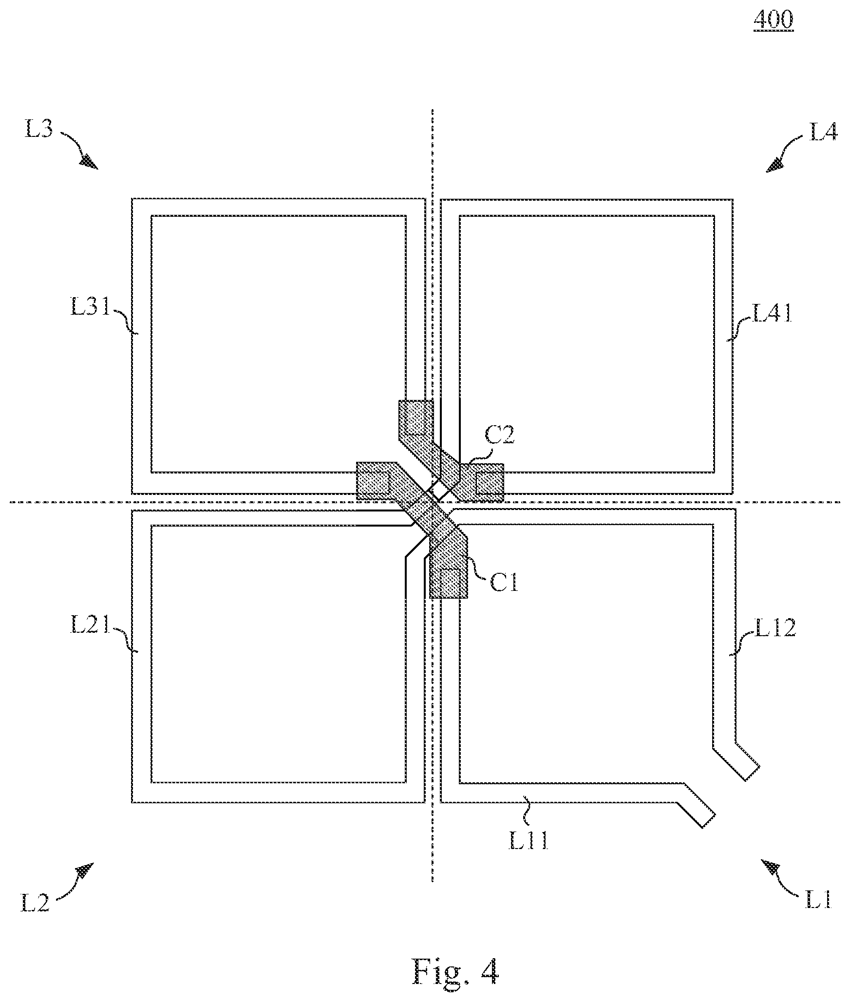
Reference is now made to . illustrates a diagram of an inductor apparatus 400 according to yet another embodiment of the present invention. The inductor apparatus 400 includes four coil loop L 1 ˜L 4 and the centrally bridging line sections C 1 ˜C 2 .
The four coil loops L 1 ˜L 4 are arranged in an order of a clockwise manner and includes the first quadrant coil loop L 1 , the second quadrant coil loop L 2 , the third quadrant coil loop L 3 and the fourth quadrant coil loop L 4 . According to the arrangement relation of any one of the quadrant coil loop with the other three quadrant coil loops, each of the quadrant coil loops has a former quadrant coil loop, a latter quadrant coil loop and a diagonal quadrant coil loop disposed nearby.
Take the first quadrant coil loop L 1 as an example, the former quadrant coil loop is the fourth quadrant coil loop L 4 , the latter quadrant coil loop is the second quadrant coil loop L 2 and the diagonal quadrant coil loop is the third quadrant coil loop L 3 . Each of the rest of the three quadrant coil loops has an identical relation with other quadrant coil loops and is not further described herein.
The first quadrant coil loop L 1 includes the first section L 11 and the second section L 12 . The first section L 11 thereof is directly coupled to the first I/O terminal IO 1 , and the second section L 12 thereof is directly coupled to the second I/O terminal IO 2 .
The second quadrant coil loop L 2 includes the first section L 21 directly coupled to the second section L 12 of the first quadrant coil loop L 1 through the central area of the four coil loops L 1 ˜L 4 . The third quadrant coil loop L 3 includes the first section L 31 centrally bridged over the central area to the first section L 11 of the first quadrant coil loop L 1 by using the centrally bridging line sections C 1 . The fourth quadrant coil loop L 4 includes the first section L 41 directly coupled to the first section L 21 of the second quadrant coil loop L 2 through central area and centrally bridged over the central area to the first section L 31 of the third quadrant coil loop L 3 by using the centrally bridging line sections C 2 .
As a result, as illustrated in , in the present embodiment, each of the first quadrant coil loop L 1 , the second quadrant coil loop L 2 , the third quadrant coil loop L 3 and the fourth quadrant coil loop L 4 includes a one-circle structure. As a result, the laterally bridging line sections are not necessary to be used in the inductor apparatus 400 .
In summary, the inductor apparatus of the present invention can keep the number of the centrally bridging line sections and the laterally bridging line sections unchanged, by using the disposition method of the first section, the second section and the third section of each of the quadrant coil loops, without being affected by the number of the circles of each of the quadrant coil loops. The design of the inductor coil can be simplified and the efficiency thereof can be improved.
The aforementioned descriptions represent merely the preferred embodiments of the present invention, without any intention to limit the scope of the present invention thereto. Various equivalent changes, alterations, or modifications based on the claims of present invention are all consequently viewed as being embraced by the scope of the present invention.
Figures (1)
Citations
This patent cites (7)
- US9196409
- US2015/0065068
- US2019/0279809
- US2020/0312521
- US2021/0065966
- USWO 2005096328
- USWO 2009101565