Imaging Optical System, Image Capture Device, and Camera System
Abstract
An imaging optical system includes a first lens group having positive power, a second lens group, and a third lens group. The first lens group includes a sub-lens group G 1 A, an aperture stop, and a sub-lens group G 1 B. The sub-lens group G 1 A includes a lens L 1 A 1 and a lens L 1 A 2 . An object-side surface of the lens L 1 A 1 is convex toward an object. The third lens group includes a lens L 3 E having negative power and a lens L 3 P located adjacent to, and closer to the object than, the lens L 3 E.
Claims (20)
1. An imaging optical system comprising: a first lens group having positive power; a second lens group having power; and a third lens group having power, the first lens group, the second lens group, and the third lens group being arranged in this order such that the first lens group is located closer to an object than any other lens group of the imaging optical system is, the first lens group and the third lens group being configured not to move along an optical axis of the imaging optical system while the imaging optical system is focusing, the second lens group including at least one lens LFN having negative power, the at least one lens LFN being configured to move along the optical axis such that a first interval and a second interval change while the imaging optical system is focusing, the first interval being an interval on the optical axis between a surface, located closest to an image, of the first lens group and a surface, located closest to the object, of the second lens group, the second interval being an interval on the optical axis between a surface, located closest to the image, of the second lens group and a surface, located closest to the object, of the third lens group, the first lens group including: a sub-lens group G 1 A; an aperture stop; and a sub-lens group G 1 B, the sub-lens group G 1 A, the aperture stop, and the sub-lens group G 1 B being arranged in this order such that the sub-lens group G 1 A is located closer to the object than any other component of the first lens group is, the sub-lens group G 1 A including: a lens L 1 A 1 ; and a lens L 1 A 2 located adjacent to, and closer to the image than, the lens L 1 A 1 , the lens L 1 A 1 and the lens L 1 A 2 being arranged in this order such that the lens L 1 A 1 is located closer to the object than any other component, including the lens L 1 A 2 , of the sub-lens group G 1 A is, an object-side surface of the lens L 1 A 1 being convex toward the object, the third lens group including: a lens L 3 E having negative power; and a lens L 3 P located adjacent to, and closer to the object than, the lens L 3 E, the lens L 3 E and the lens L 3 P being arranged in this order such that the lens L 3 E is located closer to the image than any other component, including the lens L 3 P, of the third lens group is.
Show 19 dependent claims
2. The imaging optical system of claim 1 , wherein the lens L 1 A 2 has negative power, an image-side surface of the lens L 1 A 2 having a concave surface shape, and the imaging optical system satisfies the following inequalities (1), (2), and (3): 0.1< L _ STO/LL< 0.6 (1) 2.0< LL/Y< 10.0 (2) 0.1< TG 3 A/TL 3 E< 20 (3)
3. The imaging optical system of claim 1 , wherein the lens L 1 A 1 has positive power.
4. The imaging optical system of claim 1 , wherein the imaging optical system satisfies the following Inequality (4): | FL _ L 3 E/FL|< 7 (4)
5. The imaging optical system of claim 1 , wherein an object-side surface of the lens L 3 E has a concave surface shape, the imaging optical system satisfies the following Inequality (5): −1< q< 4.5 (5)
6. The imaging optical system of claim 1 , wherein at least one of an image-side surface or an object-side surface is convex toward the aperture stop, the image-side surface being a surface of a lens located adjacent to, and closer to the object than, the aperture stop, the object-side surface being a surface of a lens located adjacent to, and closer to the image than, the aperture stop.
7. The imaging optical system of claim 1 , wherein the imaging optical system satisfies the following Inequality (6): 0.25< TG 3 P/TG 3 M< 20 (6)
8. The imaging optical system of claim 1 , wherein the imaging optical system satisfies the following Inequality (7): 0.05 <TSTO/Y< 0.5 (7)
9. The imaging optical system of claim 1 , wherein the lens L 3 P has positive power.
10. The imaging optical system of claim 1 , wherein an object-side surface of the lens L 3 E has a concave surface shape.
11. The imaging optical system of claim 1 , wherein the sub-lens group G 1 B includes at least two lenses.
12. The imaging optical system of claim 1 , wherein the sub-lens group G 1 B includes a lens L 1 BE having positive power, the lens L 1 BE being located closest to the image in the sub-lens group G 1 B.
13. The imaging optical system of claim 12 , wherein the imaging optical system satisfies the following Inequality (8): | NdL 1 BE−NdL 2 F|< 0.2 (8)
14. The imaging optical system of claim 3 , wherein the imaging optical system satisfies the following Inequality (9): 0.3< BF/Y< 3 (9)
15. The imaging optical system of claim 1 , wherein the imaging optical system satisfies the following Inequality (10): 0.3 <TFOC _ L 3 E/FL< 3 (10)
16. The imaging optical system of claim 1 , wherein the imaging optical system satisfies the following inequality: 0.2< FL _ G 1 B/FL _ GT< 5
17. The imaging optical system of claim 1 , wherein the imaging optical system satisfies the following inequality: 0.1< TG 3/ FL< 2
18. The imaging optical system of claim 1 , wherein while the imaging optical system is focusing to make a transition from an infinity in-focus state toward a close-object in-focus state, a surface, located closest to the object, of the second lens group moves toward the image.
19. A camera system comprising: an interchangeable lens unit including the imaging optical system of claim 1 ; and a camera body including: an image sensor configured to receive an optical image formed by the imaging optical system and transform the optical image into an electrical image signal; and a camera mount, the camera body being configured to be connected removably to the interchangeable lens unit via the camera mount, the interchangeable lens unit forming the optical image of the object on the image sensor.
20. An image capture device configured to transform an optical image of an object into an electrical image signal and display and/or store the electrical image signal transformed, the image capture device comprising: the imaging optical system of claim 1 configured to form the optical image of the object; and an image sensor configured to transform the optical image formed by the imaging optical system into the electrical image signal.
Full Description
Show full text →
CROSS-REFERENCE TO RELATED APPLICATIONS
The present application is based upon, and claims the benefit of priority to, Japanese Patent Application No. 2021-089674, filed on May 28, 2021, and Japanese Patent Application No. 2022-048824, filed on Mar. 24, 2022, the entire contents of which are hereby incorporated by reference.
TECHNICAL FIELD
The present disclosure generally relates to an imaging optical system, an image capture device, and a camera system. More particularly, the present disclosure relates to an imaging optical system with the ability to compensate for various types of aberrations sufficiently, and also relates to an image capture device and camera system including such an imaging optical system.
BACKGROUND ART
WO 2016/194111 A1 discloses an imaging optical system including a first lens group having positive power, a second lens group which moves during focusing, and a third lens group. The first, second, and third lens groups are arranged in this order such that the first lens group is located closer to an object than the second or third lens group and that the third lens group is located closer to an image than the first or second lens group.
SUMMARY
The present disclosure provides an imaging optical system with the ability to compensate for various types of aberrations sufficiently, and an image capture device and camera system including such an imaging optical system.
An imaging optical system according to an aspect of the present disclosure includes: a first lens group having positive power; a second lens group having power; and a third lens group having power. The first, second, and third lens groups are arranged in this order such that the first lens group is located closer to an object than any other lens group of the imaging optical system is. The first lens group and the third lens group do not move along an optical axis of the imaging optical system while the imaging optical system is focusing. The second lens group includes at least one lens LFN having negative power. The at least one lens LFN moves along the optical axis such that a first interval and a second interval change while the imaging optical system is focusing. The first interval is an interval on the optical axis between a surface, located closest to an image, of the first lens group and a surface, located closest to the object, of the second lens group. The second interval is an interval on the optical axis between a surface, located closest to the image, of the second lens group and a surface, located closest to the object, of the third lens group.
The first lens group includes a sub-lens group G 1 A, an aperture stop, and a sub-lens group G 1 B. The sub-lens group G 1 A, the aperture stop, and the sub-lens group G 1 B are arranged in this order such that the sub-lens group G 1 A is located closer to the object than any other component of the first lens group is.
The sub-lens group G 1 A includes a lens L 1 A 1 and a lens L 1 A 2 located adjacent to, and closer to the image than, the lens L 1 A 1 . The lens L 1 A 1 and the lens L 1 A 2 are arranged in this order such that the lens L 1 A 1 is located closer to the object than any other component, including the lens L 1 A 2 , of the sub-lens group G 1 A is.
An object-side surface of the lens L 1 A 1 is convex toward the object.
The third lens group includes a lens L 3 E having negative power, and a lens L 3 P located adjacent to, and closer to the object than, the lens L 3 E. The lens L 3 E and the lens L 3 P are arranged in this order such that the lens L 3 E is located closer to the image than any other component, including the lens L 3 P, of the third lens group is.
A camera system according to another aspect of the present disclosure includes: an interchangeable lens unit including the imaging optical system described above; and a camera body including an image sensor to receive an optical image formed by the imaging optical system and transform the optical image into an electrical image signal and a camera mount. The camera body is to be connected removably to the interchangeable lens unit via the camera mount. The interchangeable lens unit forms the optical image of the object on the image sensor.
An image capture device according to still another aspect of the present disclosure transforms an optical image of an object into an electrical image signal and displays and/or stores the electrical image signal thus transformed. The image capture device includes the imaging optical system described above and an image sensor. The imaging optical system forms the optical image of the object. The image sensor transforms the optical image formed by the imaging optical system into the electrical image signal.
BRIEF DESCRIPTION OF DRAWINGS
The figures depict one or more implementations in accordance with the present teaching, by way of example only, not by way of limitations. In the figures, like reference numerals refer to the same or similar elements.
illustrates lens arrangements showing an infinity in-focus state of an imaging optical system according to a first embodiment (corresponding to a first example of numerical values);
illustrates longitudinal aberration diagrams showing what state the imaging optical system assumes in the first example of numerical values;
illustrates lens arrangements showing an infinity in-focus state of an imaging optical system according to a second embodiment (corresponding to a second example of numerical values);
illustrates longitudinal aberration diagrams showing what state the imaging optical system assumes in the second example of numerical values;
illustrates lens arrangements showing an infinity in-focus state of an imaging optical system according to a third embodiment (corresponding to a third example of numerical values);
illustrates longitudinal aberration diagrams showing what state the imaging optical system assumes in the third example of numerical values;
illustrates lens arrangements showing an infinity in-focus state of an imaging optical system according to a fourth embodiment (corresponding to a fourth example of numerical values);
illustrates longitudinal aberration diagrams showing what state the imaging optical system assumes in the fourth example of numerical values;
illustrates lens arrangements showing an infinity in-focus state of an imaging optical system according to a fifth embodiment (corresponding to a fifth example of numerical values);
illustrates longitudinal aberration diagrams showing what state the imaging optical system assumes in the fifth example of numerical values;
illustrates a schematic configuration for a digital camera according to the first embodiment; and
illustrates a schematic configuration for a lens interchangeable digital camera system according to the first embodiment.
DESCRIPTION OF EMBODIMENTS
Embodiments of the present disclosure will now be described in detail with reference to the accompanying drawings as appropriate. Note that unnecessarily detailed description will be omitted. For example, detailed description of already well-known matters and redundant description of substantially the same configuration will be omitted. This is done to avoid making the following description overly redundant and thereby help one of ordinary skill in the art understand the present disclosure easily.
In addition, note that the accompanying drawings and the following description are provided by the applicant to help one of ordinary skill in the art understand the present disclosure fully and should not be construed as limiting the scope of the present disclosure, which is defined by the appended claims.
First to Fifth Embodiments
, 3 , 5 , 7 , and 9 illustrate lens arrangements and operations of an imaging optical system according to first to fifth embodiments, respectively.
As used herein, the terms “in-focus,” “focusing,” and “focus” refer to the imaging optical system is “in focus” state, “focusing,” and in “focus” unless otherwise stated. In addition, the “optical axis” as used herein refers to the optical axis of the imaging optical system unless otherwise stated.
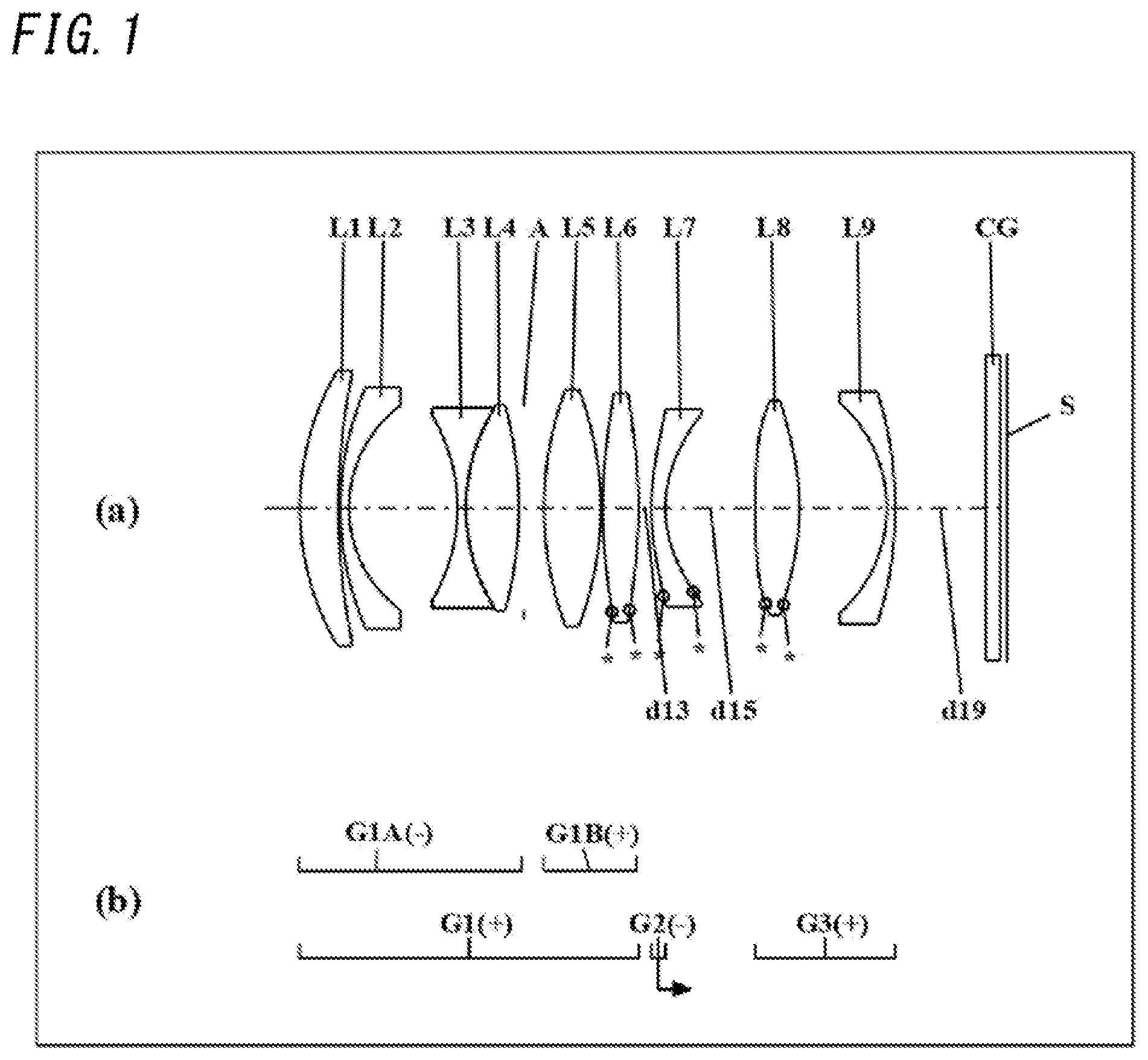
Portion (a) of , 3 , 5 , 7 , and 9 illustrates lens arrangements in the infinity in-focus state. In portion (a) of , 3 , 5 , 7 , and 9 , the straight line drawn at the right end indicates the position of the image plane S (corresponding to a plane on which the image sensor is disposed, and which faces the object as will be described later). Thus, in each of these drawings, the left side corresponds to the object side. In addition, a low-pass filter or cover glass CG, for example, may be arranged between the lens group on the last stage facing the image plane S and the image plane S. Note that respective portions (a) of , 3 , 5 , 7 , and 9 have the same aspect ratio.
In portion (a) of , 3 , 5 , 7 , and 9 , the asterisk (*) attached to a surface of a particular lens indicates that the surface is an aspheric surface. Note that in the lenses, an object-side surface or an image-side surface having no asterisks is a spherical surface.
On the second row of portion (b) of , 3 , 5 , 7 , and 9 , the respective lens groups are designated by the reference signs G 1 -G 3 corresponding to their respective positions shown in portion (a). Furthermore, the signs (+) and (−) added to the reference signs of the respective lens groups G 1 -G 3 in portion (b) of , 3 , 5 , 7 , and 9 indicate the powers of the respective lens groups G 1 -G 3 . That is to say, the positive sign (+) indicates positive power, and the negative sign (−) indicates negative power.
Also, on the first row of portion (b) of , 3 , 5 , 7 , and 9 , shown are sub-lens groups of the lens groups G 1 -G 3 shown on the second row of portion (b). The sign (+) or (−) is added to each sub-lens group. The signs (+) and (−) added to the reference signs of the respective sub-lens groups (G 1 A, G 1 B, G 2 A, G 2 B) in portion (b) of , 3 , 5 , 7 , and 9 indicate the powers of the respective sub-lens groups (G 1 A, G 1 B, G 2 A, G 2 B). That is to say, the positive sign (+) indicates positive power, and the negative sign (−) indicates negative power.
Also, either on the first row or second row of portion (b) of , 3 , 5 , 7 , and 9 , an arrow indicating the direction of movement while the imaging optical system is focusing to make a transition from the infinity in-focus state toward the close-object in-focus state is drawn under the reference sign of a particular lens group or particular sub-lens group.
First Embodiment
An imaging optical system according to a first embodiment will be described with reference to .
illustrates lens arrangements showing an infinity in-focus state of an imaging optical system according to a first embodiment and also illustrates how the imaging optical system operates in the infinity in-focus state.
As shown in , the imaging optical system according to this embodiment includes a first lens group G 1 having positive power, a second lens group G 2 having negative power, a third lens group G 3 having positive power, and a cover glass CG. The first, second, and third lens groups G 1 -G 3 and the cover glass CG are arranged in this order such that the first lens group G 1 is located closer to the object than any other member of the imaging optical system and that the cover glass CG is located closer to the image than any other member of the imaging optical system.
The first lens group G 1 is made up of a sub-lens group G 1 A having negative power, an aperture stop A, and a sub-lens group G 1 B having positive power. The sub-lens group G 1 A, the aperture stop A, and the sub-lens group G 1 B are arranged in this order such that the sub-lens group G 1 A is located closest to the object in the first lens group G 1 and that the sub-lens group G 1 B is located closest to the image in the first lens group G 1 .
The sub-lens group G 1 A is made up of a first lens L 1 having positive power, a second lens L 2 having negative power, a third lens L 3 having negative power, and a fourth lens L 4 having positive power. The first to fourth lenses L 1 -L 4 are arranged in this order such that the first lens L 1 is located closest to the object in the sub-lens group G 1 A and that the fourth lens L 4 is located closest to the image in the sub-lens group G 1 A.
The sub-lens group G 1 B is made up of a fifth lens L 5 having positive power and a sixth lens L 6 having positive power. The fifth and sixth lenses L 5 , L 6 are arranged in this order such that the fifth lens L 5 is located closer to the object than the sixth lens L 6 is and that the sixth lens L 6 is located closer to the image than the fifth lens L 5 is.
The third lens L 3 and the fourth lens L 4 are bonded together with an adhesive such as a UV curable resin to form a bonded lens. In other words, the bonded lens includes the third lens L 3 and the fourth lens L 4 .
The second lens group G 2 consists of a seventh lens L 7 having negative power.
The third lens group G 3 is made up of an eighth lens L 8 having positive power and a ninth lens L 9 having negative power.
Next, the respective lenses that form these lens groups of the imaging optical system according to this embodiment will be described.
First, the respective lenses that form the sub-lens group G 1 A will be described.
The first lens L 1 is a meniscus lens having a convex object-side surface. The second lens L 2 is a meniscus lens having a convex object-side surface. The third lens L 3 is a biconcave lens. The fourth lens L 4 is a biconvex lens. The first lens L 1 is an example of the lens L 1 A 1 . The second lens L 2 is an example of the lens L 1 A 2 .
Next, the respective lenses that form the sub-lens group G 1 B will be described.
The fifth lens L 5 is a biconvex lens. The sixth lens L 6 is a biconvex lens, both surfaces of which are aspheric surfaces. The sixth lens L 6 is an example of the lens L 1 BE.
Next, the lens that forms the second lens group G 2 will be described.
The seventh lens L 7 is a meniscus lens having a convex object-side surface. Both surfaces of the seventh lens L 7 are aspheric surfaces. The seventh lens L 7 is an example of the lens LFN and the lens L 2 F.
Next, the respective lenses that form the third lens group G 3 will be described.
The eighth lens L 8 is a biconvex lens, both surfaces of which are aspheric surfaces. The ninth lens L 9 is a meniscus lens having a convex image-side surface. The eighth lens L 8 is an example of the lens L 3 P. The ninth lens L 9 is an example of the lens L 3 E.
While the imaging optical system according to this embodiment is focusing to make a transition from an infinity in-focus state toward a close-object in-focus state, the first lens group GT does not move, the aperture stop A does not move, either, the second lens group G 2 moves along the optical axis toward the image, and the third lens group G 3 does not move.
That is to say, the imaging optical system performs focusing such that an interval (d 13 ) on the optical axis between a surface, located closest to the image, of the first lens group GT and a surface, located closest to the object, of the second lens group G 2 and an interval (d 15 ) on the optical axis between a surface, located closest to the image, of the second lens group G 2 and a surface, located closest to the object, of the third lens group G 3 change.
More specifically, while the imaging optical system is focusing to make a transition from the infinity in-focus state toward the close-object in-focus state, the seventh lens L 7 moves toward the image.
In this embodiment, the surface, located closest to the image, of the first lens group G 1 is the image-side surface of the sixth lens L 6 . The surface, located closest to the object, of the second lens group G 2 is the object-side surface of the seventh lens L 7 . The surface, located closest to the image, of the second lens group G 2 is the image-side surface of the seventh lens L 7 . The surface, located closest to the object, of the third lens group G 3 is the object-side surface of the eighth lens L 8 .
Second Embodiment
An imaging optical system according to a second embodiment will be described with reference to .
illustrates lens arrangements showing an infinity in-focus state of an imaging optical system according to a second embodiment and also illustrates how the imaging optical system operates in the infinity in-focus state.
As shown in , the imaging optical system according to this embodiment includes a first lens group G 1 having positive power, a second lens group G 2 having negative power, a third lens group G 3 having negative power, and a cover glass CG. The first, second, and third lens groups G 1 -G 3 and the cover glass CG are arranged in this order such that the first lens group G 1 is located closer to the object than any other member of the imaging optical system and that the cover glass CG is located closer to the image than any other member of the imaging optical system.
The first lens group G 1 is made up of a sub-lens group G 1 A having negative power, an aperture stop A, and a sub-lens group G 1 B having positive power. The sub-lens group G 1 A, the aperture stop A, and the sub-lens group G 1 B are arranged in this order such that the sub-lens group G 1 A is located closest to the object in the first lens group G 1 and that the sub-lens group G 1 B is located closest to the image in the first lens group G 1 .
The sub-lens group G 1 A is made up of a first lens L 1 having positive power, a second lens L 2 having negative power, a third lens L 3 having negative power, and a fourth lens L 4 having positive power. The first to fourth lenses L 1 -L 4 are arranged in this order such that the first lens L 1 is located closest to the object in the sub-lens group G 1 A and that the fourth lens L 4 is located closest to the image in the sub-lens group G 1 A.
The sub-lens group G 1 B is made up of a fifth lens L 5 having positive power and a sixth lens L 6 having positive power. The fifth and sixth lenses L 5 , L 6 are arranged in this order such that the fifth lens L 5 is located closer to the object than the sixth lens L 6 is and that the sixth lens L 6 is located closer to the image than the fifth lens L 5 is.
The third lens L 3 and the fourth lens L 4 are bonded together with an adhesive such as a UV curable resin to form a bonded lens. In other words, the bonded lens includes the third lens L 3 and the fourth lens L 4 .
The second lens group G 2 consists of a seventh lens L 7 having negative power.
The third lens group G 3 is made up of an eighth lens L 8 having positive power and a ninth lens L 9 having negative power.
Next, the respective lenses that form these lens groups of the imaging optical system according to this embodiment will be described.
First, the respective lenses that form the sub-lens group G 1 A will be described.
The first lens L 1 is a meniscus lens having a convex object-side surface. The second lens L 2 is a meniscus lens having a convex object-side surface. The third lens L 3 is a biconcave lens. The fourth lens L 4 is a biconvex lens. The first lens L 1 is an example of the lens L 1 A 1 . The second lens L 2 is an example of the lens L 1 A 2 .
Next, the respective lenses that form the sub-lens group G 1 B will be described.
The fifth lens L 5 is a biconvex lens. The sixth lens L 6 is a biconvex lens, both surfaces of which are aspheric surfaces. The sixth lens L 6 is an example of the lens L 1 BE.
Next, the lens that forms the second lens group G 2 will be described.
The seventh lens L 7 is a meniscus lens having a convex object-side surface. Both surfaces of the seventh lens L 7 are aspheric surfaces. The seventh lens L 7 is an example of the lens LFN and the lens L 2 F.
Next, the respective lenses that form the third lens group G 3 will be described.
The eighth lens L 8 is a biconvex lens, both surfaces of which are aspheric surfaces. The ninth lens L 9 is a meniscus lens having a convex image-side surface. The eighth lens L 8 is an example of the lens L 3 P. The ninth lens L 9 is an example of the lens L 3 E.
While the imaging optical system according to this embodiment is focusing to make a transition from an infinity in-focus state toward a close-object in-focus state, the first lens group GT does not move, the aperture stop A does not move, either, the second lens group G 2 moves along the optical axis toward the image, and the third lens group G 3 does not move.
That is to say, the imaging optical system performs focusing such that an interval (d 13 ) on the optical axis between a surface, located closest to the image, of the first lens group GT and a surface, located closest to the object, of the second lens group G 2 and an interval (d 15 ) on the optical axis between a surface, located closest to the image, of the second lens group G 2 and a surface, located closest to the object, of the third lens group G 3 change.
More specifically, while the imaging optical system is focusing to make a transition from the infinity in-focus state toward the close-object in-focus state, the seventh lens L 7 moves toward the image.
In this embodiment, the surface, located closest to the image, of the first lens group G 1 is the image-side surface of the sixth lens L 6 . The surface, located closest to the object, of the second lens group G 2 is the object-side surface of the seventh lens L 7 . The surface, located closest to the image, of the second lens group G 2 is the image-side surface of the seventh lens L 7 . The surface, located closest to the object, of the third lens group G 3 is the object-side surface of the eighth lens L 8 .
Third Embodiment
An imaging optical system according to a third embodiment will be described with reference to .
illustrates lens arrangements showing an infinity in-focus state of an imaging optical system according to a third embodiment and also illustrates how the imaging optical system operates in the infinity in-focus state.
As shown in , the imaging optical system according to this embodiment includes a first lens group G 1 having positive power, a second lens group G 2 having negative power, a third lens group G 3 having positive power, and a cover glass CG. The first, second, and third lens groups G 1 -G 3 and the cover glass CG are arranged in this order such that the first lens group G 1 is located closer to the object than any other member of the imaging optical system and that the cover glass CG is located closer to the image than any other member of the imaging optical system.
The first lens group G 1 is made up of a sub-lens group G 1 A having negative power, an aperture stop A, and a sub-lens group G 1 B having positive power. The sub-lens group G 1 A, the aperture stop A, and the sub-lens group G 1 B are arranged in this order such that the sub-lens group G 1 A is located closest to the object in the first lens group G 1 and that the sub-lens group G 1 B is located closest to the image in the first lens group G 1 .
The sub-lens group G 1 A is made up of a first lens L 1 having positive power, a second lens L 2 having negative power, a third lens L 3 having negative power, and a fourth lens L 4 having positive power. The first to fourth lenses L 1 -L 4 are arranged in this order such that the first lens L 1 is located closest to the object in the sub-lens group G 1 A and that the fourth lens L 4 is located closest to the image in the sub-lens group G 1 A.
The sub-lens group G 1 B is made up of a fifth lens L 5 having positive power and a sixth lens L 6 having positive power. The fifth and sixth lenses L 5 , L 6 are arranged in this order such that the fifth lens L 5 is located closer to the object than the sixth lens L 6 is and that the sixth lens L 6 is located closer to the image than the fifth lens L 5 is.
The third lens L 3 and the fourth lens L 4 are bonded together with an adhesive such as a UV curable resin to form a bonded lens. In other words, the bonded lens includes the third lens L 3 and the fourth lens L 4 .
The second lens group G 2 consists of a seventh lens L 7 having negative power.
The third lens group G 3 is made up of an eighth lens L 8 having positive power, a ninth lens L 9 having positive power, and a tenth lens L 10 having negative power.
Next, the respective lenses that form these lens groups of the imaging optical system according to this embodiment will be described.
First, the respective lenses that form the sub-lens group G 1 A will be described.
The first lens L 1 is a meniscus lens having a convex object-side surface. The second lens L 2 is a meniscus lens having a convex object-side surface. The third lens L 3 is a biconcave lens. The fourth lens L 4 is a biconvex lens. The first lens L 1 is an example of the lens L 1 A 1 . The second lens L 2 is an example of the lens L 1 A 2 .
Next, the respective lenses that form the sub-lens group G 1 B will be described.
The fifth lens L 5 is a biconvex lens. The sixth lens L 6 is a biconvex lens, both surfaces of which are aspheric surfaces. The sixth lens L 6 is an example of the lens L 1 BE.
Next, the lens that forms the second lens group G 2 will be described.
The seventh lens L 7 is a meniscus lens having a convex object-side surface. Both surfaces of the seventh lens L 7 are aspheric surfaces. The seventh lens L 7 is an example of the lens LFN and the lens L 2 F.
Next, the respective lenses that form the third lens group G 3 will be described.
The eighth lens L 8 is a biconvex lens, both surfaces of which are aspheric surfaces. The ninth lens L 9 is a biconvex lens. The tenth lens L 10 is a meniscus lens having a convex image-side surface. The ninth lens L 9 is an example ofthe lens L 3 P. The tenth lens L 10 is an example of the lens L 3 E.
While the imaging optical system according to this embodiment is focusing to make a transition from an infinity in-focus state toward a close-object in-focus state, the first lens group GT does not move, the aperture stop A does not move, either, the second lens group G 2 moves along the optical axis toward the image, and the third lens group G 3 does not move.
That is to say, the imaging optical system performs focusing such that an interval (d 13 ) on the optical axis between a surface, located closest to the image, of the first lens group GT and a surface, located closest to the object, of the second lens group G 2 and an interval (d 15 ) on the optical axis between a surface, located closest to the image, of the second lens group G 2 and a surface, located closest to the object, of the third lens group G 3 change.
More specifically, while the imaging optical system is focusing to make a transition from the infinity in-focus state toward the close-object in-focus state, the seventh lens L 7 moves toward the image.
In this embodiment, the surface, located closest to the image, of the first lens group G 1 is the image-side surface of the sixth lens L 6 . The surface, located closest to the object, of the second lens group G 2 is the object-side surface of the seventh lens L 7 . The surface, located closest to the image, of the second lens group G 2 is the image-side surface of the seventh lens L 7 . The surface, located closest to the object, of the third lens group G 3 is the object-side surface of the eighth lens L 8 .
Fourth Embodiment
An imaging optical system according to a fourth embodiment will be described with reference to .
illustrates lens arrangements showing an infinity in-focus state of an imaging optical system according to a fourth embodiment and also illustrates how the imaging optical system operates in the infinity in-focus state.
As shown in , the imaging optical system according to this embodiment includes a first lens group G 1 having positive power, a second lens group G 2 having negative power, a third lens group G 3 having positive power, and a cover glass CG. The first, second, and third lens groups G 1 -G 3 and the cover glass CG are arranged in this order such that the first lens group G 1 is located closer to the object than any other member of the imaging optical system and that the cover glass CG is located closer to the image than any other member of the imaging optical system.
The first lens group G 1 is made up of a sub-lens group G 1 A having negative power, an aperture stop A, and a sub-lens group G 1 B having positive power. The sub-lens group G 1 A, the aperture stop A, and the sub-lens group G 1 B are arranged in this order such that the sub-lens group G 1 A is located closest to the object in the first lens group G 1 and that the sub-lens group G 1 B is located closest to the image in the first lens group G 1 .
The sub-lens group G 1 A is made up of a first lens L 1 having positive power, a second lens L 2 having negative power, a third lens L 3 having negative power, and a fourth lens L 4 having positive power. The first to fourth lenses L 1 -L 4 are arranged in this order such that the first lens L 1 is located closest to the object in the sub-lens group G 1 A and that the fourth lens L 4 is located closest to the image in the sub-lens group G 1 A.
The sub-lens group G 1 B is made up of a fifth lens L 5 having positive power and a sixth lens L 6 having positive power. The fifth and sixth lenses L 5 , L 6 are arranged in this order such that the fifth lens L 5 is located closer to the object than the sixth lens L 6 is and that the sixth lens L 6 is located closer to the image than the fifth lens L 5 is.
The third lens L 3 and the fourth lens L 4 are bonded together with an adhesive such as a UV curable resin to form a bonded lens. In other words, the bonded lens includes the third lens L 3 and the fourth lens L 4 .
The second lens group G 2 is made up of a seventh lens L 7 having positive power, an eighth lens L 8 having positive power, and a ninth lens L 9 having negative power.
The eighth lens L 8 and the ninth lens L 9 are bonded together with an adhesive such as a UV curable resin to form a bonded lens. In other words, the bonded lens includes the eighth lens L 8 and the ninth lens L 9 .
The third lens group G 3 is made up of a tenth lens L 10 having positive power and an eleventh lens L 11 having negative power.
Next, the respective lenses that form these lens groups of the imaging optical system according to this embodiment will be described.
First, the respective lenses that form the sub-lens group G 1 A will be described.
The first lens L 1 is a meniscus lens having a convex object-side surface. The second lens L 2 is a meniscus lens having a convex object-side surface. The third lens L 3 is a biconcave lens. The fourth lens L 4 is a biconvex lens. The first lens L 1 is an example of the lens L 1 A 1 . The second lens L 2 is an example of the lens L 1 A 2 .
Next, the respective lenses that form the sub-lens group G 1 B will be described.
The fifth lens L 5 is a biconvex lens. The sixth lens L 6 is a biconvex lens, both surfaces of which are aspheric surfaces. The sixth lens L 6 is an example of the lens L 1 BE.
Next, the respective lenses that form the second lens group G 2 will be described.
The seventh lens L 7 is a meniscus lens having a convex image-side surface, which is an aspheric surface. The eighth lens L 8 is a biconvex lens. The ninth lens L 9 is a biconcave lens. The seventh lens L 7 is an example of the lens L 2 F. The ninth lens L 9 is an example of the lens LFN.
Next, the respective lenses that form the third lens group G 3 will be described.
The tenth lens L 10 is a biconvex lens, both surfaces of which are aspheric surfaces. The eleventh lens L 11 is a meniscus lens having a convex image-side surface. The tenth lens L 10 is an example of the lens L 3 P. The eleventh lens L 11 is an example of the lens L 3 E.
While the imaging optical system according to this embodiment is focusing to make a transition from an infinity in-focus state toward a close-object in-focus state, the first lens group G 1 does not move, the aperture stop A does not move, either, the second lens group G 2 moves along the optical axis toward the image, and the third lens group G 3 does not move.
That is to say, the imaging optical system performs focusing such that an interval (d 13 ) on the optical axis between a surface, located closest to the image, of the first lens group G 1 and a surface, located closest to the object, of the second lens group G 2 and an interval (d 19 ) on the optical axis between a surface, located closest to the image, of the second lens group G 2 and a surface, located closest to the object, of the third lens group G 3 change.
More specifically, while the imaging optical system is focusing to make a transition from the infinity in-focus state toward the close-object in-focus state, the seventh lens L 7 , the eighth lens L 8 , and the ninth lens L 9 moves together toward the image.
In this embodiment, the surface, located closest to the image, of the first lens group G 1 is the image-side surface of the sixth lens L 6 . The surface, located closest to the object, of the second lens group G 2 is the object-side surface of the seventh lens L 7 . The surface, located closest to the image, of the second lens group G 2 is the image-side surface of the ninth lens L 9 . The surface, located closest to the object, of the third lens group G 3 is the object-side surface of the tenth lens L 10 .
Fifth Embodiment
An imaging optical system according to a fifth embodiment will be described with reference to .
illustrates lens arrangements showing an infinity in-focus state of an imaging optical system according to a fifth embodiment and also illustrates how the imaging optical system operates in the infinity in-focus state.
As shown in , the imaging optical system according to this embodiment includes a first lens group G 1 having positive power, a second lens group G 2 having negative power, a third lens group G 3 having negative power, and a cover glass CG. The first, second, and third lens groups G 1 -G 3 and the cover glass CG are arranged in this order such that the first lens group G 1 is located closer to the object than any other member of the imaging optical system and that the cover glass CG is located closer to the image than any other member of the imaging optical system.
The first lens group G 1 is made up of a sub-lens group G 1 A having negative power, an aperture stop A, and a sub-lens group G 1 B having positive power. The sub-lens group G 1 A, the aperture stop A, and the sub-lens group G 1 B are arranged in this order such that the sub-lens group G 1 A is located closest to the object in the first lens group G 1 and that the sub-lens group G 1 B is located closest to the image in the first lens group G 1 .
The sub-lens group G 1 A is made up of a first lens L 1 having positive power, a second lens L 2 having negative power, a third lens L 3 having negative power, and a fourth lens L 4 having positive power. The first to fourth lenses L 1 -L 4 are arranged in this order such that the first lens L 1 is located closest to the object in the sub-lens group G 1 A and that the fourth lens L 4 is located closest to the image in the sub-lens group G 1 A.
The first lens L 1 and the second lens L 2 are bonded together with an adhesive such as a UV curable resin to form a first bonded lens. Likewise, the third lens L 3 and the fourth lens L 4 are also bonded together with an adhesive such as a UV curable resin to form a second bonded lens. In other words, the first bonded lens includes the first lens L 1 and the second lens L 2 , and the second bonded lens includes the third lens L 3 and the fourth lens L 4 .
The sub-lens group G 1 B is made up of a fifth lens L 5 having positive power and a sixth lens L 6 having positive power. The fifth and sixth lenses L 5 , L 6 are arranged in this order such that the fifth lens L 5 is located closer to the object than the sixth lens L 6 is and that the sixth lens L 6 is located closer to the image than the fifth lens L 5 is.
The second lens group G 2 is made up of a sub-lens group G 2 A having negative power and a sub-lens group G 2 B having positive power. The sub-lens group G 2 A and the sub-lens group G 2 B are arranged in this order such that the sub-lens group G 2 A is located closer to the object than the sub-lens group G 2 B is and that the sub-lens group G 2 B is located closer to the image than the sub-lens group G 1 B is.
The sub-lens group G 2 A consists of a seventh lens L 7 having negative power.
The sub-lens group G 2 B consists of an eighth lens L 8 having positive power.
The third lens group G 3 is made up of a ninth lens L 9 having positive power and a tenth lens L 10 having negative power.
Next, the respective lenses that form these lens groups of the imaging optical system according to this embodiment will be described.
First, the respective lenses that form the sub-lens group G 1 A will be described.
The first lens L 1 is a meniscus lens having a convex object-side surface. The second lens L 2 is a meniscus lens having a convex object-side surface. The third lens L 3 is a biconcave lens. The fourth lens L 4 is a biconvex lens. The first lens L 1 is an example of the lens L 1 A 1 . The second lens L 2 is an example of the lens L 1 A 2 .
Next, the respective lenses that form the sub-lens group G 1 B will be described.
The fifth lens L 5 is a biconvex lens. The sixth lens L 6 is a biconvex lens, both surfaces of which are aspheric surfaces. The sixth lens L 6 is an example of the lens L 1 BE.
Next, the lens that forms the sub-lens group G 2 A will be described.
The seventh lens L 7 is a biconcave lens, both surfaces of which are aspheric surfaces. The seventh lens L 7 is an example of the lens LFN and the lens L 2 F.
Next, the lens that forms the sub-lens group G 2 B will be described.
The eighth lens L 8 is a meniscus lens having a convex image-side surface. Both surfaces of the eighth lens L 8 are aspheric surfaces.
Next, the respective lenses that form the third lens group G 3 will be described.
The ninth lens L 9 is a meniscus lens having a convex image-side surface. The tenth lens L 10 is a meniscus lens having a convex image-side surface. The ninth lens L 9 is an example of the lens L 3 P. The tenth lens L 10 is an example of the lens L 3 E.
While the imaging optical system according to this embodiment is focusing to make a transition from an infinity in-focus state toward a close-object in-focus state, the first lens group G 1 does not move, the aperture stop A does not move, either, the sub-lens group G 2 A in the second lens group G 2 moves along the optical axis toward the image, the sub-lens group G 2 B in the second lens group G 2 moves along the optical axis toward the object, and the third lens group G 3 does not move.
That is to say, the imaging optical system performs focusing such that an interval (d 13 ) on the optical axis between a surface, located closest to the image, of the first lens group G 1 and a surface, located closest to the object, of the second lens group G 2 and an interval (d 17 ) on the optical axis between a surface, located closest to the image, of the second lens group G 2 and a surface, located closest to the object, of the third lens group G 3 change.
More specifically, while the imaging optical system is focusing to make a transition from the infinity in-focus state toward the close-object in-focus state, the seventh lens L 7 moves toward the image and the eighth lens L 8 moves toward the object.
In this embodiment, the surface, located closest to the image, of the first lens group G 1 is the image-side surface of the sixth lens L 6 . The surface, located closest to the object, of the second lens group G 2 is the object-side surface of the seventh lens L 7 . The surface, located closest to the image, of the second lens group G 2 is the image-side surface of the eighth lens L 8 . The surface, located closest to the object, of the third lens group G 3 is the object-side surface of the ninth lens L 9 .
(Conditions and Advantages)
Next, conditions that an imaging optical system such as the ones according to the first to fifth embodiments described above may satisfy will be described. That is to say, a plurality of conditions may be defined for the imaging optical system according to each of these five embodiments. In that case, an imaging optical system, of which the configuration satisfies all of these conditions, is most advantageous. Alternatively, an imaging optical system that achieves its expected advantages by satisfying any of the individual conditions to be described below may also be obtained.
An imaging optical system according to the present disclosure, such as the imaging optical systems according to the first to fifth embodiments described above, includes: a first lens group G 1 having positive power; a second lens group G 2 having power; and a third lens group G 3 having power. The first, second, and third lens groups G 1 , G 2 , G 3 are arranged in this order such that the first lens group G 1 is located closer to an object than any other lens group of the imaging optical system is. The first lens group G 1 and the third lens group G 3 do not move along the optical axis while the imaging optical system is focusing. In other words, while the imaging optical system is focusing, the first lens group G 1 and the third lens group G 3 stand still along the optical axis. The second lens group includes at least one lens LFN having negative power. The at least one lens LFN moves along the optical axis such that a first interval and a second interval change while the imaging optical system is focusing. The first interval is an interval on the optical axis between a surface, located closest to an image, of the first lens group G 1 and a surface, located closest to the object, of the second lens group G 2 . The second interval is an interval on the optical axis between a surface, located closest to the image, of the second lens group G 2 and a surface, located closest to the object, of the third lens group G 3 .
The first lens group G 1 includes: a sub-lens group G 1 A; an aperture stop A; and a sub-lens group G 1 B. The sub-lens group G 1 A, the aperture stop A, and the sub-lens group G 1 B are arranged in this order such that the sub-lens group G 1 A is located closer to the object than any other component of the first lens group G 1 is.
The sub-lens group G 1 A includes: a lens L 1 A 1 ; and a lens L 1 A 2 located adjacent to, and closer to the image than, the lens L 1 A 1 . The lens L 1 A 1 and the lens L 1 A 2 are arranged in this order such that the lens L 1 A 1 is located closer to the object than any other component, including the lens L 1 A 2 , of the sub-lens group G 1 A is.
An object-side surface of the lens L 1 A 1 is convex toward the object.
The third lens group G 3 includes: a lens L 3 E having negative power; and a lens L 3 P located adjacent to, and closer to the object than, the lens L 3 E. The lens L 3 E and the lens L 3 P are arranged in this order such that the lens L 3 E is located closer to the image than any other component, including the lens L 3 P, of the third lens group is.
This basic configuration enables providing an imaging optical system with the ability to compensate for various types of aberrations sufficiently.
In addition, this basic configuration allows even an imaging optical system having as high an F value as about 2.4 or more that ensures high brightness to achieve excellent performance and downsizing at a time.
The imaging optical system having this basic configuration preferably satisfies the condition expressed by the following Inequality (1): 0.1< L _ STO/LL< 0.6 (1) where L_STO is an interval on the optical axis between an object-side surface of the lens L 1 A 1 and the aperture stop A, and LL is an interval on the optical axis between the object-side surface of the lens L 1 A 1 and an image-side surface of the lens L 3 E. Note that the units of these parameters should be the same (e.g., the units of L_STO and LL are both millimeters).
The condition expressed by this Inequality (1) defines a preferred range of the ratio of the interval L_STO on the optical axis between the object-side surface of the lens L 1 A 1 and the aperture stop A to the interval LL on the optical axis between the object-side surface of the lens L 1 A 1 and the image-side surface of the lens L 3 E.
If the L_STO/LL ratio were equal to or less than the lower limit value defined by this Inequality (1), then the aperture stop A would be so close to the object-side end of the imaging optical system as to cause a significant increase in exit pupil length, thus making the lens diameter of either the second lens group G 2 or the third lens group G 3 too large.
On the other hand, if the L_STO/LL ratio were equal to or greater than the upper limit value defined by this Inequality (1), then the aperture stop A would be so distant from the object-side end of the imaging optical system as to cause an excessive increase in the lens diameter of the lens L 1 A 1 .
To enhance the advantage described above, at least one of the conditions expressed by the following Inequalities (1a) and (1b) is preferably satisfied: 0.15< L _ STO/LL (1a) L _ STO/LL< 0.50 (1b).
More preferably, to further enhance the advantage described above, at least one of the conditions expressed by the following Inequalities (1c) and (1d) may be satisfied: 0.20< L _ STO/LL (1c) L _ STO/LL< 0.45 (1d).
The imaging optical system having the basic configuration preferably satisfies the condition expressed by the following Inequality (2): 2.0< LL/Y< 10.0 (2) where Y is an image height of the imaging optical system in an infinity in-focus state. Note that the units of these parameters should be the same (e.g., the units of LL and Y are both millimeters).
The condition expressed by this Inequality (2) defines a preferred range of the ratio of the interval LL on the optical axis between the object-side surface of the lens L 1 A 1 and the image-side surface of the lens L 3 E to the image height Y of the imaging optical system in the infinity in-focus state.
If the LL/Y ratio were equal to or less than the lower limit value defined by this Inequality (2), then the overall length of the imaging optical system would be too short to arrange the respective lenses and the air gaps appropriately, thus making it difficult to enhance the performance.
On the other hand, if the LL/Y ratio were equal to or greater than the upper limit value defined by this Inequality (2), then the overall length of the imaging optical system would be too long.
To enhance the advantage described above, at least one of the conditions expressed by the following Inequalities (2a) and (2b) is preferably satisfied: 3.0< LL/Y (2a) LL/Y< 7.0 (2b).
More preferably, to further enhance the advantage described above, at least one of the conditions expressed by the following Inequalities (2c) and (2d) may be satisfied: 3.5< LL/Y (2c) LL/Y< 5.0 (2d).
The imaging optical system having the basic configuration preferably satisfies the condition expressed by the following Inequality (3): 0.1< TG 3 A/TL 3 E< 20 (3) where TG 3 A is a maximum value of an air gap on the optical axis within the third lens group G 3 , and TL 3 E is a thickness on the optical axis of the lens L 3 E.
The condition expressed by this Inequality (3) defines a preferred range of the ratio of the maximum value TG 3 A of an air gap on the optical axis within the third lens group G 3 (i.e., the maximum one of the respective air gaps between adjacent lenses within the third lens group G 3 ) to the thickness TL 3 E on the optical axis of the lens L 3 E.
If the TG 3 A/TL 3 E ratio were equal to or less than the lower limit value defined by this Inequality (3), then the maximum air gap within the third lens group G 3 would be so narrow as to cause a significant increase in the power of the lenses in the third lens group G 3 , thus widening the astigmatic difference.
On the other hand, if the TG 3 A/TL 3 E ratio were equal to or greater than the upper limit value defined by the Inequality (3), then the maximum air gap within the third lens group G 3 would be so wide as to make the overall length of the imaging optical system too long.
To enhance the advantage described above, at least one of the conditions expressed by the following Inequalities (3a) and (3b) is preferably satisfied: 0.2< TG 3 A/TL 3 E (3a) TG 3 A/TL 3 E< 15 (3b).
More preferably, to further enhance the advantage described above, at least one of the conditions expressed by the following Inequalities (3c) and (3d) may be satisfied: 0.45< TG 3 A/TL 3 E (3c) TG 3 A/TL 3 E< 12 (3b).
In the imaging optical system having the basic configuration described above, the lens L 1 A 1 preferably has positive power.
This makes it easier to make correction to an excessive astigmatic difference.
The imaging optical system having the basic configuration preferably satisfies the condition expressed by the following Inequality (4): | FL _ L 3 E/FL|< 7 (4) where FL_L 3 E is a focal length of the lens L 3 E, and FL is a focal length of the entire imaging optical system. Note that the units of these parameters should be the same (e.g., the units of FL_L 3 E and FL are both millimeters).
The condition expressed by this Inequality (4) defines a preferred range of the ratio of the focal length FL_L 3 E of the lens L 3 E to the focal length FL of the entire imaging optical system.
If the FL_L 3 E/FL ratio were greater than the upper limit value defined by this Inequality (4), then the focal length of the lens L 3 E would increase too much to correct the field curvature sufficiently.
At least one of the conditions expressed by the following Inequalities (4a) and (4b) is preferably satisfied: 0.50<| FL _ L 3 E/FL| (4a) | FL _ L 3 E/FL|< 6 (4b).
The advantage described above would be enhanced by satisfying the condition expressed by this Inequality (4b). If the |FL_L 3 E/FL| ratio were equal to or less than the lower limit value defined by this Inequality (4a), the focal length of the lens L 3 E would decrease too much to avoid correcting the field curvature excessively.
More preferably, to further enhance the advantage described above, at least one of the conditions expressed by the following Inequalities (4c) and (4d) may be satisfied: 0.80<| FL _ L 3 E/FL| (4c) | FL _ L 3 E/FL|< 4 (4d).
In the imaging optical system having the basic configuration, the object-side surface of the lens L 3 E preferably has a concave surface shape. The imaging optical system preferably satisfies the condition expressed by following Inequality (5): −1< q< 4.5 (5) where q is a shape factor of the lens L 3 E and is given by q =( RrL 3 E+RfL 3 E )/( RrL 3 E−RfL 3 E ) where RfL 3 E is a radius of curvature of the object-side surface of the lens L 3 E, and RrL 3 E is a radius of curvature of an image-side surface of the lens L 3 E. Note that the units of these parameters should be the same (e.g., the units of RfL 3 E and RrL 3 E are both millimeters).
The condition expressed by this Inequality (5) defines a preferred range of the shape factor of the lens L 3 E.
If the shape factor q were equal to or less than the lower limit value defined by this Inequality (5), then the effect of correcting the field curvature of the lens L 3 E would increase too much to correct its field curvature moderately.
On the other hand, if the shape factor q were equal to or greater than the upper limit value defined by this Inequality (5), then the effect of correcting the field curvature of the lens L 3 E would decrease too much to correct its field curvature sufficiently.
To enhance the advantage described above, at least one of the conditions expressed by the following Inequalities (5a) and (5b) is preferably satisfied: −0.8< q (5a) q< 4 (5b).
More preferably, to further enhance the advantage described above, at least one of the conditions expressed by the following Inequalities (5c) and (5d) may be satisfied: −0.6< q (5c) q< 3 (5d).
In the imaging optical system having the basic configuration described above, at least one of an image-side surface or an object-side surface is preferably convex toward the aperture stop A. The image-side surface is a surface of a lens located adjacent to, and closer to the object than, the aperture stop A. The object-side surface is a surface of a lens located adjacent to, and closer to the image than, the aperture stop A. This enables widening the interval around an effective diameter between the lenses, thus making it easier to place the aperture stop A. In , the lens located adjacent to, and closer to the object than, the aperture stop A is the fourth lens L 4 . Also, in , the lens located adjacent to, and closer to the image than, the aperture stop A is the fifth lens L 5 .
In the imaging optical system having the basic configuration described above, all positive lenses (i.e., lenses having positive power) and all negative lenses (i.e., lens having negative power) included in the third lens group G 3 preferably satisfy the condition expressed by the following Inequality (6): 0.25< TG 3 P/TG 3 M< 20 (6) where TG 3 P is a sum of thicknesses on the optical axis of all positive lenses included in the third lens group G 3 , and TG 3 M is a sum of thicknesses on the optical axis of all negative lenses included in the third lens group G 3 . Note that the units of these parameters should be the same (e.g., the units of TG 3 P and TG 3 M are both millimeters).
The condition expressed by this Inequality (6) defines a preferred range of the ratio of the sum of thicknesses TG 3 P on the optical axis of all positive lenses included in the third lens group G 3 to the sum of thicknesses TG 3 M on the optical axis of all negative lenses included in the third lens group G 3 .
If the TG 3 P/TG 3 M ratio were equal to or less than the lower limit value defined by this Inequality (6), then the sum of thicknesses of those lenses having positive power in the third lens group G 3 would decrease too much to avoid correcting the field curvature excessively.
On the other hand, if the TG 3 P/TG 3 M ratio were equal to or greater than the upper limit value defined by this Inequality (6), then the sum of thicknesses of those lenses having positive power in the third lens group G 3 would increase so much as to make the imaging optical system oversized.
To enhance the advantage described above, at least one of the conditions expressed by the following Inequalities (6a) and (6b) is preferably satisfied: 0.5< TG 3 P/TG 3 M (6a) TG 3 P/TG 3 M< 15 (6b).
More preferably, to further enhance the advantage described above, at least one of the conditions expressed by the following Inequalities (6c) and (6d) may be satisfied: 0.8< TG 3 P/TG 3 M (6c) TG 3 P/TG 3 M< 13 (6d).
The imaging optical system having the basic configuration described above preferably satisfies the condition expressed by the following Inequality (7): 0.05 <TSTO/Y< 0.5 (7) where TSTO is an interval on the optical axis between an image-side surface of a lens located adjacent to, and closer to the object than, the aperture stop A and an object-side surface of a lens located adjacent to, and closer to the image than, the aperture stop A, and Y is an image height of the imaging optical system in an infinity in-focus state. Note that the units of these parameters should be the same (e.g., the units of TSTO and Y are both millimeters).
The condition expressed by this Inequality (7) defines a preferred range of the ratio of the interval TSTO on the optical axis between the image-side surface of a lens located adjacent to, and closer to the object than, the aperture stop A and the object-side surface of a lens located adjacent to, and closer to the image than, the aperture stop A to the image height Y of the imaging optical system in the infinity in-focus state.
If the TSTO/Y ratio were equal to or less than the lower limit value defined by this Inequality (7), then the interval on the optical axis between two lenses that are arranged to interpose the aperture stop A between themselves would be too narrow to arrange the aperture stop A between the two lenses easily.
On the other hand, if the TSTO/Y ratio were equal to or greater than the upper limit value defined by this Inequality (7), then the interval on the optical axis between the two lenses that are arranged to interpose the aperture stop A between themselves would be so wide as to make the imaging optical system oversized.
To enhance the advantage described above, at least one of the conditions expressed by the following Inequalities (7a) and (7b) is preferably satisfied: 0.10 <TSTO/Y (7a) TSTO/Y< 0.45 (7b).
More preferably, to further enhance the advantage described above, at least one of the conditions expressed by the following Inequalities (7c) and (7d) may be satisfied: 0.15 <TSTO/Y (7c) TSTO/Y< 0.40 (7d).
In the imaging optical system having the basic configuration described above, the third lens group G 3 is preferably made up of a lens L 3 E and a lens L 3 P, which are arranged in this order such that the lens L 3 E is located closer to the image than the lens L 3 P is. The lens L 3 P preferably has positive power.
This makes it easier to reduce the size of the third lens group G 3 .
In the imaging optical system having the basic configuration described above, an object-side surface of the lens L 3 E preferably has a concave surface shape.
This makes it easier to reduce field curvature.
In the imaging optical system having the basic configuration described above, the sub-lens group G 1 B preferably includes at least two lenses.
This makes it easier to correct spherical aberration.
In the imaging optical system having the basic configuration described above, the sub-lens group G 1 B preferably includes a lens L 1 BE having positive power. The lens L 1 BE is located closest to the image in the sub-lens group G 1 B.
This makes it easier to correct spherical aberration.
The imaging optical system having the basic configuration described above preferably satisfies the condition expressed by the following Inequality (8): | NdL 1 BE−NdL 2 F|< 0.2 (8) where NdL 1 BE is a d-line refractive index of the lens L 1 BE, and NdL 2 F is a d-line refractive index of a lens L 2 F located closest to the object in the second lens group G 2 .
The condition expressed by this Inequality (8) defines a preferred range of the absolute value of the difference between the d-line refractive index NdL 1 BE of the lens L 1 BE and the d-line refractive index NdL 2 F of a lens L 2 F located closest to the object in the second lens group G 2 .
If the absolute value of the difference in their refractive index were equal to or greater than the upper limit value defined by this Inequality (8), then it would not be easy to correct the spherical aberration and comatic aberration in the infinity in-focus state.
To enhance the advantage described above, the condition expressed by the following Inequality (8a) is preferably satisfied: | NdL 1 BE−NdL 2 F|< 0.1 (8a).
More preferably, to further enhance the advantage described above, the condition expressed by the following Inequality (8b) may be satisfied: | NdL 1 BE−NdL 2 F|< 0.01 (8b).
The imaging optical system having the basic configuration described above preferably satisfies the condition expressed by the following Inequality (9): 0.3< BF/Y< 3 (9) where BF is an interval on the optical axis between an image-side surface of the lens L 3 E and an image plane S, and Y is an image height of the imaging optical system in an infinity in-focus state. Note that the units of these parameters should be the same (e.g., the units of BF and Y are both millimeters).
The condition expressed by this Inequality (9) defines a preferred range of the ratio of the interval BF on the optical axis between an image-side surface of the lens L 3 E and the image plane S to the image height Y of the imaging optical system in the infinity in-focus state.
If the BF/Y ratio were equal to or less than the lower limit value defined by this Inequality (9), then the interval between the image-side surface of the lens L 3 E and the image plane S would be too narrow to easily place a member for coupling this imaging optical system to an image sensor to be disposed on the image plane S.
On the other hand, if the BF/Y ratio were equal to or greater than the upper limit value defined by this Inequality (9), then the interval between the image-side surface of the lens L 3 E and the image plane S would be so wide as to make the imaging optical system oversized.
To enhance the advantage described above, at least one of the conditions expressed by the following Inequalities (9a) and (9b) is preferably satisfied: 0.5< BF/Y (9a) BF/Y< 2.0 (9b).
More preferably, to further enhance the advantage described above, at least one of the conditions expressed by the following Inequalities (9c) and (9d) may be satisfied: 0.7< BF/Y (9c) BF/Y< 1.2 (9d).
Even more preferably, to further enhance the advantage described above, at least one of the conditions expressed by the following Inequalities (9e) and (9f) may be satisfied: 0.75< BF/Y (9e) BF/Y< 0.95 (9f).
The imaging optical system having the basic configuration described above preferably satisfies the condition expressed by the following Inequality (10): 0.3 <TFOC _ L 3 E/FL< 3 (10) where TFOC_L 3 E is an interval on the optical axis between an object-side surface of a lens L 2 F located closest to the object in the second lens group G 2 and an image-side surface of the lens L 3 E when the imaging optical system is in an infinity in-focus state, and FL is a focal length of the entire imaging optical system. Note that the units of these parameters should be the same (e.g., the units of TFOC_L 3 E and FL are both millimeters).
The condition expressed by this Inequality (10) defines a preferred range of the ratio of the interval TFOC_L 3 E on the optical axis between the object-side surface of a lens L 2 F located closest to the object in the second lens group G 2 and the image-side surface of the lens L 3 E when the imaging optical system is in an infinity in-focus state to the focal length FL of the entire imaging optical system.
If the TFOC_L 3 E/FL ratio were equal to or less than the lower limit value defined by this Inequality (10), then the magnitude of movement of the lenses that move during focusing would be so small as to make the shooting distance range too narrow to find a focus.
On the other hand, if the TFOC_L 3 E/FL ratio were equal to or greater than the upper limit value defined by this Inequality (10), then the magnitude of movement of the lenses that move during focusing would increase so much as to make the imaging optical system oversized.
To enhance the advantage described above, at least one of the conditions expressed by the following Inequalities (10a) and (10b) is preferably satisfied: 0.5 <TFOC _ L 3 E/FL (10a) TFOC _ L 3 E/FL< 2 (10b).
More preferably, to further enhance the advantage described above, at least one of the conditions expressed by the following Inequalities (10c) and (10d) may be satisfied: 0.6 <TFOC _ L 3 E/FL (10c) TFOC _ L 3 E/FL< 1 (10d).
The imaging optical system having the basic configuration described above preferably satisfies the condition expressed by the following Inequality (11): 0.5 <TSTO _ L 3 E/FL< 6 (11) where TSTO_L 3 E is an interval on the optical axis between the aperture stop A and an image-side surface of the lens L 3 E, and FL is a focal length of the entire imaging optical system. Note that the units of these parameters should be the same (e.g., the units of TSTO_L 3 E and FL are both millimeters).
The condition expressed by this Inequality (11) defines a preferred range of the ratio of the interval TSTO_L 3 E on the optical axis between the aperture stop A and the image-side surface of the lens L 3 E to the focal length FL of the entire imaging optical system.
If the TSTO_L 3 E/FL ratio were equal to or less than the lower limit value defined by this Inequality (11), then the interval on the optical axis between the aperture stop A and the third lens group G 3 would be so narrow and the magnitude of movement of the lenses that move during focusing would be so small as to make the shooting distance range too narrow to find a focus.
On the other hand, if the TSTO_L 3 E/FL ratio were equal to or greater than the upper limit value defined by this Inequality (11), then the interval on the optical axis between the aperture stop A and the third lens group G 3 would be so wide as to make the imaging optical system oversized.
To enhance the advantage described above, at least one of the conditions expressed by the following Inequalities (11a) and (11b) is preferably satisfied: 0.9 <TSTO _ L 3 E/FL (11a) TSTO _ L 3 E/FL< 5 (11b).
More preferably, to further enhance the advantage described above, at least one of the conditions expressed by the following Inequalities (11c) and (11d) may be satisfied: 1.3 <TSTO _ L 3 E/FL (11c) TSTO _ L 3 E/FL< 4 (11d).
The imaging optical system having the basic configuration described above preferably satisfies the condition expressed by the following Inequality (12): 0.2< FL _ G 1 B/FL _ G 1<5 (12) where FL_G 1 B is a focal length of the sub-lens group G 1 B, and FL_G 1 is a focal length of the first lens group G 1 . Note that the units of these parameters should be the same (e.g., the units of FL_G 1 B and FL_G 1 are both millimeters).
The condition expressed by this Inequality (12) defines a preferred range of the ratio of the focal length FL_G 1 B of the sub-lens group G 1 B to the focal length FL_G 1 of the first lens group G 1 .
If the FL_G 1 B/FL_G 1 ratio were equal to or less than the lower limit value defined by this Inequality (12), then the focal length FL_G 1 B of the sub-lens group G 1 B would be too short to correct the spherical aberration sufficiently.
On the other hand, if the FL_G 1 B/FL_G 1 ratio were equal to or greater than the upper limit value defined by this Inequality (12), then the focal length FL_G 1 B of the sub-lens group G 1 B would be too long to avoid correcting the spherical aberration excessively.
To enhance the advantage described above, at least one of the conditions expressed by the following Inequalities (12a) and (12b) is preferably satisfied: 0.5< FL _ G 1 B/FL _ G 1 (12a) FL _ G 1 B/FL _ G 1<4 (12b).
More preferably, to further enhance the advantage described above, at least one of the conditions expressed by the following Inequalities (12c) and (12d) may be satisfied: 0.6< FL _ G 1 B/FL _ G 1 (12c) FL _ G 1 B/FL _ G 1<2 (12d).
The imaging optical system having the basic configuration described above preferably satisfies the condition expressed by the following Inequality (13): 0.1< TG 3/ FL< 2 (13) where TG 3 is an interval on the optical axis between a surface, located closest to the object, of the third lens group G 3 and a surface, located closest to the image, of the third lens group G 3 , and FL is a focal length of the entire imaging optical system. Note that the units of these parameters should be the same (e.g., the units of TG 3 and FL are both millimeters).
The condition expressed by this Inequality (13) defines a preferred range of the ratio of the interval TG 3 on the optical axis between a surface, located closest to the object, of the third lens group G 3 and a surface, located closest to the image, of the third lens group G 3 to the focal length FL of the entire imaging optical system.
If the TG 3 /FL ratio were equal to or less than the lower limit value defined by this Inequality (13), then the interval on the optical axis between those surfaces of the third lens group G 3 would be too narrow to easily avoid producing field curvature.
On the other hand, if the TG 3 /FL ratio were equal to or greater than the upper limit value defined by this Inequality (13), then the interval on the optical axis between those surfaces of the third lens group G 3 would be so wide as to make the imaging optical system oversized.
To enhance the advantage described above, at least one of the conditions expressed by the following Inequalities (13a) and (13b) is preferably satisfied: 0.15< TG 3/ FL (13a) TG 3/ FL< 1.4 (13b).
More preferably, to further enhance the advantage described above, at least one of the conditions expressed by the following Inequalities (13c) and (13d) may be satisfied: 0.2< TG 3/ FL (13c) TG 3/ FL< 0.8 (13d).
In the imaging optical system having the basic configuration described above, while the imaging optical system is focusing to make a transition from an infinity in-focus state toward a close-object in-focus state, a surface, located closest to the object, of the second lens group G 2 preferably moves toward the image. In , for example, the surface, located closest to the object, of the second lens group G 2 is the object-side surface of the seventh lens L 7 .
This makes it easier to find a focus when the shooting distance has changed.
Also, the second lens group G 2 is preferably made up of at most three lenses including the lens LFN.
This may reduce the number of lenses required for finding a focus, thus simplifying the focusing mechanism.
(Schematic Configuration for Image Capture Device to which First Embodiment is Applied)
illustrates a schematic configuration for an image capture device, to which the imaging optical system of the first embodiment is applied. Optionally, the imaging optical system according to the second, third, fourth, or fifth embodiment is also applicable to the image capture device.
The image capture device 100 includes a housing 104 , an image sensor 102 , and the imaging optical system 101 according to the first embodiment. Specifically, the image capture device 100 may be implemented as a digital camera, for example.
The housing 104 includes a lens barrel 302 . The lens barrel 302 holds the respective lens groups and the aperture stop A that form the imaging optical system 101 .
The image sensor 102 is disposed at the image plane S of the imaging optical system 101 according to the first embodiment.
The image capture device 100 transforms an optical image of an object into an electrical image signal and displays and/or stores the image signal thus transformed. The image capture device 100 may include, for example, at least one of a monitor on which the image signal is displayed or a memory to store the image signal.
The imaging optical system 101 forms an optical image of the object. The image sensor 102 transforms the optical image, formed by the imaging optical system 101 , into an electrical image signal.
The imaging optical system 101 is configured such that an interval on the optical axis between a surface, located closest to the image, of the first lens group G 1 and a surface, located closest to the object, of the second lens group G 2 and an interval on the optical axis between a surface, located closest to the image, of the second lens group G 2 and a surface, located closest to the object, of the third lens group G 3 change. Specifically, to allow at least one lens having negative power (such as the seventh lens L 7 ) in the second lens group G 2 to move while the imaging optical system 101 is focusing, an actuator and a lens frame, which are included in the housing 104 , are attached or coupled to the at least one lens having negative power.
This provides an image capture device 100 with the ability to compensate for various types of aberrations sufficiently.
In the example described above, the imaging optical system 101 according to the first embodiment is applied to a digital camera. However, this is only an example and should not be construed as limiting. Alternatively, the imaging optical system is also applicable to a surveillance camera, a smartphone, or any of various other types of image capture devices.
(Schematic Configuration for Camera System to which First Embodiment is Applied)
illustrates a schematic configuration for a camera system, to which the imaging optical system of the first embodiment is applied. Alternatively, the imaging optical system according to the second, third, fourth, or fifth embodiment is also applicable to the camera system.
The camera system 200 includes a camera body 201 and an interchangeable lens unit 300 to be connected removably to the camera body 201 .
The camera body 201 includes an image sensor 202 , a monitor 203 , a memory, a camera mount 204 , and a viewfinder 205 . The image sensor 202 receives an optical image formed by the imaging optical system 301 of the interchangeable lens unit 300 and transforms the optical image into an electrical image signal. The monitor 203 displays the image signal transformed by the image sensor 202 . The memory stores the image signal.
The imaging optical system 301 of the interchangeable lens unit 300 is the imaging optical system according to the first embodiment. The interchangeable lens unit 300 makes the imaging optical system 301 form an optical image of the object on the image sensor 202 .
The interchangeable lens unit 300 includes not only the imaging optical system 301 but also a lens barrel 302 and a lens mount 304 . The lens barrel 302 holds the respective lens groups and aperture stop A of the imaging optical system 301 . The lens mount 304 is configured to be connected removably to the camera mount 204 of the camera body 201 .
In this manner, the camera mount 204 and the lens mount 304 are physically connected together. In addition, the camera mount 204 and the lens mount 304 also electrically connect together a controller in the camera body 201 and a controller in the interchangeable lens unit 300 . That is to say, the camera mount 204 and the lens mount 304 also serve as interfaces that allow themselves to exchange signals with each other.
The imaging optical system 301 includes the respective lens groups held by the lens barrel 302 and cover glass CG of the camera body 201 . The imaging optical system 301 includes the first lens group G 1 , the second lens group G 2 , the aperture stop A, and the third lens group G 3 . The imaging optical system 301 is configured such that an interval on the optical axis between a surface, located closest to the image, of the first lens group G 1 and a surface, located closest to the object, of the second lens group G 2 and an interval on the optical axis between a surface, located closest to the image, of the second lens group G 2 and a surface, located closest to the object, of the third lens group G 3 change. Specifically, to allow at least one lens having negative power (such as the seventh lens L 7 ) in the second lens group G 2 to move while the imaging optical system 301 is focusing, an actuator and a lens frame, which are controlled by the controller in the interchangeable lens unit 300 , are arranged.
Other Embodiments
The first, second, third, fourth, and fifth embodiments have been described as exemplary embodiments of the present disclosure. Note that the embodiments described above are only examples of the present disclosure and should not be construed as limiting. Rather, each of those embodiments may be readily modified, replaced, combined with other embodiments, provided with some additional components, or partially omitted without departing from the scope of the present disclosure.
In the first to third embodiments described above, the seventh lens L 7 that is a single lens has been described as an example of the second lens group G 2 and the lens LFN. The second lens group G 2 may be configured to allow at least one lens LFN having negative power in the second lens group G 2 to move along the optical axis such that an interval on the optical axis between a surface, located closest to an image, of the first lens group G 1 and a surface, located closest to the object, of the second lens group G 2 and an interval on the optical axis between a surface, located closest to the image, of the second lens group G 2 and a surface, located closest to the object, of the third lens group G 3 change with respect to the first lens group G 1 and the third lens group G 3 that do not move during focusing. Thus, the second lens group G 2 and the lens LFN are not limited to a single lens.
Alternatively, as described for the fourth embodiment, the second lens group G 2 includes, as a lens LFN, the ninth lens L 9 having negative power. The second lens group G 2 may include the seventh lens L 7 as a single lens and a bonded lens formed by the eighth lens L 8 and the ninth lens L 9 . The second lens group G 2 may be configured to move in its entirety during focusing. Alternatively, the second lens group G 2 may also consist of only a bonded lens which is configured to move during focusing. If an increase in the load on the focus actuator is permissible due to an increase in the weight of the lenses, setting the number of lenses that move during focusing at two or more enables compensating for various aberrations of the imaging optical system (e.g., the field curvature in the infinity in-focus state and close-object in-focus state, among other things) sufficiently.
In addition, as already described for the fifth embodiment, for example, the second lens group G 2 may also be configured such that the sub-lens group G 2 A moves toward the image and the sub-lens group G 2 B moves toward the object while the imaging optical system is focusing to make a transition from the infinity in-focus state toward the close-object in-focus state. Furthermore, the sub-lens group G 2 A or the sub-lens group G 2 B does not have to be a single lens but may also be a bonded lens. Alternatively, the sub-lens group G 2 A or the sub-lens group G 2 B may also be a group including two or more single lenses that move together. Still alternatively, the sub-lens group G 2 A or the sub-lens group G 2 B may also be a combination of a single lens and a bonded lens that move together. Yet alternatively, the second lens group G 2 may include, between the sub-lens group G 2 A and the sub-lens group G 2 B, at least one lens that does not move during focusing. This makes it easier to reduce the magnitude of focus shift and variation in aberration during focusing. In addition, allowing the increase in the number of focus actuators as described above enables compensating for various aberrations of the imaging optical system (e.g., the field curvature in the infinity in-focus state and close-object in-focus state, among other things).
In the first to fifth embodiments described above, each of the lens groups that form the imaging optical system is supposed to consist of only refractive lenses that deflect the incoming light ray through refraction (i.e., lenses of the type that deflect the incoming light ray at the interface between two media with mutually different refractive indices). However, this is only an example and should not be construed as limiting. Alternatively, each lens group may also include diffractive lenses that deflect the incoming light ray through diffraction, refractive-diffractive hybrid lenses that deflect the incoming light ray through a combination of diffraction and refraction, or refractive index distributed lenses that deflect the incoming light ray in accordance with the distribution of refractive indices in the medium, or a combination of two or more types of these lenses. Among other things, a diffraction structure is suitably formed at the interface between two media with mutually different refractive indices in the refractive-diffractive hybrid lenses, because the diffraction efficiency would depend on the wavelength much less heavily in that case. This provides a camera system in which various types of aberrations have been compensated for sufficiently.
(Examples of Numerical Values)
Next, exemplary sets of specific numerical values that were actually adopted in the imaging optical systems with the configurations according to the first, second, third, fourth, and fifth embodiments will be described. Note that in the tables showing these exemplary sets of numerical values, the length is expressed in millimeters (mm), the angle of view is expressed in degrees (°), r indicates the radius of curvature, d indicates the surface interval, nd indicates a refractive index with respect to a d-line, υd (also denoted as “vd”) indicates an abbe number with respect to a d-line, and a surface with an asterisk (*) is an aspheric surface. The aspheric shape is defined by the following Equation (1):
Z = h 2 / r 1 + 1 - ( 1 + κ ) ( h / r ) 2 + ∑ A n h n where Z is the distance from a point on an aspheric surface, located at a height h as measured from the optical axis, to a tangent plane defined with respect to the vertex of the aspheric surface, h is the height as measured from the optical axis, r is the radius of curvature of the vertex, κ is a conic constant, and An is an n th order aspheric surface coefficient.
, 4 , 6 , 8 , and 10 are longitudinal aberration diagrams showing what state the imaging optical systems according to the first, second, third, fourth, and fifth examples of numerical values assume.
In each longitudinal aberration diagram, portion (a) shows the longitudinal aberrations at the infinity focus point, and portion (b) shows the longitudinal aberrations at the close-object focus point. Each of portions (a) and (b) of these longitudinal aberration diagrams shows spherical aberration (SA (mm)), astigmatism (AST (mm)), and distortion (DIS (%)) in this order from left to right. In each spherical aberration diagram, the ordinate indicates the F number (designated by “F” on the drawings), the solid curve indicates a characteristic in response to a d-line, the shorter dashed curve indicates a characteristic in response to an F-line, and the longer dashed curve indicates a characteristic in response to a C-line. In each astigmatism diagram, the ordinate indicates the image height (designated by “H” on the drawings), the solid curve indicates a characteristic with respect to a sagittal plane (designated by “s” on the drawings), and the dotted curve indicates a characteristic with respect to a meridional plane (designated by “m” on the drawings). Furthermore, in each distortion diagram, the ordinate indicates the image height (designated by “H” on the drawings).
(First Example of Numerical Values)
Following is a first exemplary set of numerical values for the imaging optical system corresponding to the first embodiment shown in . Specifically, as the first example of numerical values for the imaging optical system, surface data is shown in Table 1A, aspheric surface data is shown in Table 1B, various types of data in the infinity in-focus state and close-object in-focus state are shown in Table 1C, data about single lenses is shown in Table 1D, data about lens groups in the infinity in-focus state is shown in Table 1E, zoom powers of lens groups in the infinity in-focus state and close-object in-focus state are shown in Table 1F, and data about sub-lens groups is shown in Table 1G.
TABLE 1A
(Surface data)
Surface No. r d nd vd
0 (object surface) ∞ Variable
1 38.42740 5.52300 1.85996 30.5
2 94.19390 0.30000
3 43.21060 1.20000 1.49700 81.6
4 18.21170 15.51010
5 −25.82130 1.20000 1.65794 31.1
6 27.15660 0.01000 1.56732 42.8
7 27.15660 7.53000 1.59269 65.3
8 −56.61760 0.73800
9 (aperture) ∞ 2.87000
10 48.08490 8.04450 1.59282 68.6
11 −47.17840 0.30000
12* 72.83460 5.11150 1.51570 55.8
13* −66.26290 Variable
14* 33.70070 2.00000 1.51607 56.3
15* 16.81800 Variable
16* 286.14730 6.26580 1.51570 55.8
17* −34.83520 12.50120
18 −20.12450 1.20000 1.54157 51.7
19 −54.83640 12.90000
20 ∞ 2.10000 1.51680 64.2
21 ∞ 1.00000
Image plane ∞
TABLE 1B
(Aspheric surface data)
12 th surface
K = 0.00000E+00, A4 = −4.36516E−06, A6 = 4.27940E−09,
A8 = −1.31680E−11, A10 = −1.14476E−15
13 th surface
K = 0.00000E+00, A4 = 8.55335E−06, A6 = −3.38027E−09,
A8 = 0.00000E+00, A10 = 0.00000E+00
14 th surface
K = 0.00000E+00, A4 = −3.20814E−05, A6 = 3.04040E−08,
A8 = −9.83934E−12, A10 = 0.00000E+00
15 th surface
K = −1.42129E+00, A4 = −2.12498E−08, A6 = 8.60734E−09,
A8 = 2.95476E−11, A10 = 0.00000E+00
16 th surface
K = 0.00000E+00, A4 = 3.35290E−05, A6 = −1.49631E−08,
A8 = −2.39445E−12, A10 = 0.00000E+00
17 th surface
K = 0.00000E+00, A4 = 1.74131E−05, A6 = −1.58208E−08,
A8 = 3.47625E−11, A10 = −1.23868E−13
TABLE 1C
(Various types of data in infinity in-focus
state and close-object in-focus state)
Infinity Close-object
Focal length 48.2535 43.6130
F number 1.86017 1.91036
Angle of view 24.1432 23.1170
Image height 21.3629 21.6300
Total lens length 101.0000 101.0000
d0 ∞ 349.0000
d13 1.8000 6.6163
d15 12.8959 8.0795
Entrance pupil position 29.4626 29.4626
Exit pupil position −49.2742 −47.6344
Anterior principal point 30.4699 27.7515
Posterior principal point 52.7546 51.7192
TABLE 1D
(Data about single lenses)
Lens Start surface Focal length
1 1 72.1722
2 3 −64.3640
3 5 −19.9382
4 7 32.0381
5 10 41.4733
6 12 68.1328
7 14 −67.7858
8 16 60.6211
9 18 −59.4247
TABLE 1E
(Data about lens groups in infinity in-focus state)
Lens Anterior Posterior
Start Focal configuration principal principal
Group surface length length point point
1 1 34.75504 48.33710 40.47156 49.68522
2 14 −67.78580 2.00000 2.74400 3.36936
3 16 318.80580 19.96700 −63.32946 −46.99420
TABLE 1F
(Zoom powers of lens groups in infinity in-
focus state and close-object in-focus state)
Group Start surface Infinity Close-object
1 1 0.00000 −0.09798
2 14 1.87116 1.80101
3 16 0.74199 0.74189
TABLE 1G
(Data about sub-lens groups)
Group Start surface Focal length Lens configuration length
1A 1 −67.64731 31.27312
1B 10 26.92788 13.45593
(Second Example of Numerical Values)
Following is a second exemplary set of numerical values for the imaging optical system corresponding to the second embodiment shown in . Specifically, as the second example of numerical values for the imaging optical system, surface data is shown in Table 2A, aspheric surface data is shown in Table 2B, various types of data in the infinity in-focus state and close-object in-focus state are shown in Table 2C, data about single lenses is shown in Table 2D, data about lens groups in the infinity in-focus state is shown in Table 2E, zoom powers of lens groups in the infinity in-focus state and close-object in-focus state are shown in Table 2F, and data about sub-lens groups is shown in Table 2G.
TABLE 2A
(Surface data)
Surface No. r d nd Vd
0 (object surface) ∞ Variable
1 57.56070 2.54360 1.99900 18.0
2 73.66890 0.30000
3 29.97440 1.20000 1.49700 81.6
4 20.75620 8.65050
5 −26.23400 1.20000 1.65166 30.6
6 35.19010 0.01000 1.56732 42.8
7 35.19010 5.35790 1.64068 60.6
8 −285.35080 0.73800
9 (aperture) ∞ 2.87000
10 69.05930 9.80660 1.59788 64.7
11 −44.57610 0.99990
12* 43.16250 7.64130 1.51570 55.8
13* −65.81240 Variable
14* 24.13330 2.18480 1.51607 56.3
15* 15.75700 Variable
16* 532.37770 7.40260 1.51570 55.8
17* −34.64130 13.57170
18 −23.01700 1.88650 1.85057 20.8
19 −52.43680 13.34190
20 ∞ 2.10000 1.51680 64.2
21 ∞ 1.00000
Image plane ∞
TABLE 2B
(Aspheric surface data)
12 th surface
K = 0.00000E+00, A4 = −1.55697E−06, A6 = 8.96331E−09,
A8 = 1.85826E−13, A10 = 4.31685E−15
13 th surface
K = 0.00000E+00, A4 = 9.78416E−06, A6 = 6.08302E−09,
A8 = 0.00000E+00, A10 = 0.00000E+00
14 th surface
K = 0.00000E+00, A4 = −3.15483E−05, A6 = −2.40821E−09,
A8 = −7.41270E−12, A10 = 0.00000E+00
15 th surface
K = −1.42129E+00, A4 = 4.29968E−06, A6 = −1.56481E−08,
A8 = 2.83556E−11, A10 = 0.00000E+00
16 th surface
K = 0.00000E+00, A4 = 2.68728E−05, A6 = −7.77296E−09,
A8 = 9.37812E−12, A10 = 0.00000E+00
17 th surface
K = 0.00000E+00, A4 = 1.45815E−05, A6 = −9.83640E−09,
A8 = 2.93509E−11, A10 = −2.74094E−14
TABLE 2C
(Various types of data in infinity in-focus
state and close-object in-focus state)
Infinity Close-object
Focal length 48.8914 43.9759
F number 1.83100 1.85293
Angle of view 23.8296 22.9803
Image height 20.7445 21.0094
Total lens length 100.9999 100.9999
d0 ∞ 349.0010
d13 1.8000 8.2734
d15 16.3945 9.9211
Entrance pupil position 15.9492 15.9492
Exit pupil position −52.5306 −50.8265
Anterior principal point 19.2618 16.8076
Posterior principal point 52.0226 51.0489
TABLE 2D
(Data about single lenses)
Lens Start surface Focal length
1 1 244.2364
2 3 −141.9337
3 5 −22.8872
4 7 49.2173
5 10 46.8223
6 12 51.7818
7 14 −96.5405
8 16 63.3509
9 18 −49.6967
TABLE 2E
(Data about lens groups in infinity in-focus state)
Lens con- Anterior Posterior
Start Focal figuration principal principal
Group surface length length point point
1 1 37.30850 41.31780 31.95023 48.16469
2 14 −96.54048 2.18480 4.55656 5.15985
3 16 −5207.58806 22.86080 1372.04384 1093.69861
TABLE 2F
(Zoom powers of lens groups in infinity in-
focus state and close-object in-focus state)
Group Start surface Infinity Close-object
1 1 0.00000 −0.10857
2 14 1.64348 1.57837
3 16 0.79737 0.79740
TABLE 2G
(Data about sub-lens groups)
Group Start surface Focal length Lens configuration length
1A 1 −39.98984 19.26200
1B 10 26.05053 18.44779
(Third Example of Numerical Values)
Following is a third exemplary set of numerical values for the imaging optical system corresponding to the third embodiment shown in . Specifically, as the third example of numerical values for the imaging optical system, surface data is shown in Table 3A, aspheric surface data is shown in Table 3B, various types of data in the infinity in-focus state and close-object in-focus state are shown in Table 3C, data about single lenses is shown in Table 3D, data about lens groups in the infinity in-focus state is shown in Table 3E, zoom powers of lens groups in the infinity in-focus state and close-object in-focus state are shown in Table 3F, and data about sub-lens groups is shown in Table 3G.
TABLE 3A
(Surface data)
Surface No. r d nd Vd
0 (object surface) ∞ Variable
1 36.80330 5.54500 1.85825 30.8
2 86.39570 0.30000
3 46.92960 1.20000 1.49700 81.6
4 18.13980 15.57210
5 −25.78050 1.20000 1.63816 31.9
6 26.68960 0.01000 1.56732 42.8
7 26.68960 7.53000 1.60063 64.4
8 −49.63780 0.73800
9 (aperture) ∞ 2.87000
10 40.93470 8.40880 1.59282 68.6
11 −49.08610 0.30000
12* 77.80870 4.05560 1.51570 55.8
13* −148.21700 Variable
14* 51.39300 2.00000 1.51607 56.3
15* 21.93840 Variable
16* 1484.47290 5.60210 1.51570 55.8
17* −39.64080 5.66730
18 237.74480 2.58230 1.81281 42.8
19 −511.55690 5.64460
20 −20.60640 1.20000 1.53265 55.5
21 −71.04900 12.90000
22 ∞ 2.10000 1.51680 64.2
23 ∞ 1.00000
Image plane ∞
TABLE 3B
(Aspheric surface data)
12 th surface
K = 0.00000E+00, A4 = 8.30117E−06, A6 = 3.75330E−08,
A8 = 6.41432E−11, A10 = −2.10862E−13
13 th surface
K = 0.00000E+00, A4 = 2.22564E−05, A6 = 5.27589E−08,
A8 = 0.00000E+00, A10 = 0.00000E+00
14 th surface
K = 0.00000E+00, A4 = 5.65185E−06, A6 = −9.83708E−08,
A8 = 2.08923E−10, A10 = 0.00000E+00
15 th surface
K = −1.42129E+00, A4 = 2.96720E−05, A6 = −1.28984E−07,
A8 = 2.84244E−10, A10 = 0.00000E+00
16 th surface
K = 0.00000E+00, A4 = 3.66775E−05, A6 = −1.59762E−08,
A8 = −6.65434E−12, A10 = 0.00000E+00
17 th surface
K = 0.00000E+00, A4 = 1.83234E−05, A6 = −1.96132E−08,
A8 = 4.85705E−11, A10 = −1.88164E−13
TABLE 3C
(Various types of data in infinity in-focus
state and close-object in-focus state)
Infinity Close-object
Focal length 48.2530 43.7094
F number 1.86015 1.91602
Angle of view 24.1429 23.0347
Image height 21.3216 21.6212
Total lens length 101.0001 101.0001
d0 ∞ 349.0010
d13 1.8000 7.4678
d15 12.7743 7.1064
Entrance pupil position 29.3679 29.3679
Exit pupil position −49.3899 −47.6162
Anterior principal point 30.4966 27.5111
Posterior principal point 52.7660 51.6028
TABLE 3D
(Data about single lenses)
Lens Start surface Focal length
1 1 71.0364
2 3 −60.3307
3 5 −20.3678
4 7 30.0087
5 10 39.0076
6 12 99.5476
7 14 −75.9282
8 16 74.9624
9 18 200.0001
10 20 −54.9451
TABLE 3E
(Data about lens groups in infinity in-focus state)
Lens Anterior Posterior
Start Focal configuration principal principal
Group surface length length point point
1 1 36.49226 47.72950 39.44141 48.24180
2 14 −75.92820 2.00000 2.35623 3.00582
3 16 304.07442 20.69630 −55.10671 −39.94874
TABLE 3F
(Zoom powers of lens groups in infinity in-
focus state and close-object in-focus state)
Group Start surface Infinity Close-object
1 1 0.00000 −0.10369
2 14 1.76250 1.68865
3 16 0.75023 0.75012
TABLE 3G
(Data about sub-lens groups)
Group Start surface Focal length Lens configuration length
1A 1 −81.23 31.35700
1B 10 28.90376 12.76437
(Fourth Example of Numerical Values)
Following is a fourth exemplary set of numerical values for the imaging optical system corresponding to the fourth embodiment shown in . Specifically, as the fourth example of numerical values for the imaging optical system, surface data is shown in Table 4A, aspheric surface data is shown in Table 4B, various types of data in the infinity in-focus state and close-object in-focus state are shown in Table 4C, data about single lenses is shown in Table 4D, data about lens groups in the infinity in-focus state is shown in Table 4E, zoom powers of lens groups in the infinity in-focus state and close-object in-focus state are shown in Table 4F, and data about sub-lens groups is shown in Table 4G.
TABLE 4A
(Surface data)
Surface No. r d nd Vd
0 (object ∞ Variable
surface)
1 29.39070 5.60400 1.89146 25.9
2 61.19300 0.30000
3 48.48210 1.20000 1.56786 43.5
4 17.04940 12.60990
5 −24.34420 1.22250 1.66002 29.8
6 24.60200 0.01000 1.56732 42.8
7 24.60200 7.53000 1.63367 61.2
8 −61.79990 0.73800
9 (aperture) ∞ 2.87000
10 56.13210 6.84020 1.59282 68.6
11 −56.43950 0.30000
12* 94.09000 6.07110 1.51570 55.8
13* −41.15660 Variable
14 −90.82290 2.80600 1.51570 55.8
15* −42.76750 0.30000
16 223.65230 2.54500 1.99900 18.0
17 −597.37760 0.01000 1.56732 42.8
18 −597.37760 1.20000 1.64193 48.1
19 26.63510 Variable
20* 395.20950 6.52110 1.51570 55.8
21* −34.09530 12.07120
22 −23.16360 1.20000 1.74373 24.5
23 −52.81980 12.91230
24 ∞ 2.10000 1.51680 64.2
25 ∞ 1.00000
Image plane ∞
TABLE 4B
(Aspheric surface data)
12 th surface
K = 0.00000E+00, A4 = −3.39428E−06, A6 = −8.85129E−11,
A8 = −2.53310E−11, A10 = 2.40292E−14
13 th surface
K = 0.00000E+00, A4 = 1.09393E−05, A6 = −1.30330E−08,
A8 = 0.00000E+00, A10 = 0.00000E+00
15 th surface
K = −1.42129E+00, A4 = 1.18141E−05, A6 = −2.64056E−08,
A8 = 3.18637E−11, A10 = 0.00000E+00
20 th surface
K = 0.00000E+00, A4 = 3.85717E−05, A6 = −4.07250E−08,
A8 = 2.60220E−11, A10 = 0.00000E+00
21 st surface
K = 0.00000E+00, A4 = 1.85614E−05, A6 = −1.72363E−08,
A8 = 4.11325E−12, A10 = −3.11109E−14
TABLE 4C
(Various types of data in infinity in-focus
state and close-object in-focus state)
Infinity Close-object
Focal length 48.2490 43.4014
F number 1.86007 1.90207
Angle of view 24.1355 22.9886
Image height 20.5383 20.9011
Total lens length 101.0000 101.0000
d0 ∞ 349.0010
d13 1.8000 8.1183
d19 11.2386 4.9203
Entrance pupil position 26.6030 26.6030
Exit pupil position −49.0174 −47.0376
Anterior principal point 27.3627 24.4842
Posterior principal point 52.7544 51.9422
TABLE 4D
(Data about single lenses)
Lens Start surface Focal length
1 1 58.5734
2 3 −46.9589
3 5 −18.3568
4 7 28.7412
5 10 48.5707
6 12 56.3824
7 14 153.6832
8 16 163.1438
9 18 −39.6911
10 20 61.1800
11 22 −56.4459
TABLE 4E
(Data about lens groups in infinity in-focus state)
Lens Anterior Posterior
Start Focal configuration principal principal
Group surface length length point point
1 1 37.35704 45.29570 38.62975 48.15623
2 14 −82.25802 6.86100 5.31688 8.01403
3 20 484.09358 19.79230 −97.79902 −75.35954
TABLE 4F
(Zoom powers of lens groups in infinity in-focus
state and close-object in-focus state)
Group Start surface Infinity Close-object
1 1 0.00000 −0.10665
2 14 1.67336 1.59751
3 20 0.77184 0.77174
TABLE 4G
(Data about sub-lens groups)
Group Start surface Focal length Lens configuration length
1A 1 −60.46558 28.47639
1B 10 27.48965 13.21128
(Fifth Example of Numerical Values)
Following is a fifth exemplary set of numerical values for the imaging optical system corresponding to the fifth embodiment shown in . Specifically, as the fifth example of numerical values for the imaging optical system, surface data is shown in Table 5A, aspheric surface data is shown in Table 5B, various types of data in the infinity in-focus state and close-object in-focus state are shown in Table 5C, data about single lenses is shown in Table 5D, data about lens groups in the infinity in-focus state is shown in Table 5E, zoom powers of lens groups in the infinity in-focus state and close-object in-focus state are shown in Table 5F, and data about sub-lens groups is shown in Table 5G.
TABLE 5A
(Surface data)
Surface No. r d nd Vd
0 (object ∞ Variable
surface)
1 30.66690 5.91450 1.87383 28.2
2 89.32480 0.01000 1.56732 42.8
3 89.32480 1.20000 1.56476 44.3
4 18.20210 12.11990
5 −24.35250 1.20000 1.63550 33.0
6 26.77550 0.01000 1.56732 42.8
7 26.77550 7.53000 1.61871 62.6
8 −48.93580 0.73800
9 (aperture) ∞ 2.87000
10 44.13390 7.85270 1.59282 68.6
11 −49.05890 0.30000
12* 125.87800 4.61080 1.51570 55.8
13* −52.79440 Variable
14* −158.77940 4.02260 1.51607 56.3
15* 53.80920 Variable
16* −66.86380 5.00000 1.51570 55.8
17* −32.48830 Variable
18 −74.07130 3.60690 1.79788 47.0
19 −38.64790 6.31040
20 −24.65900 1.20000 1.61615 34.6
21 −86.87210 12.90000
22 ∞ 2.10000 1.51680 64.2
23 ∞ 1.00000
Image plane ∞
TABLE 5B
(Aspheric surface data)
12 th surface
K = 0.00000E+00, A4 = −6.37727E−06, A6 = −1.76312E−09,
A8 = 3.35755E−11, A10 = −5.80543E−14
13 th surface
K = 0.00000E+00, A4 = 1.00000E−05, A6 = 3.57664E−09,
A8 = 0.00000E+00, A10 = 0.00000E+00
14 th surface
K = 0.00000E+00, A4 = 4.63373E−05, A6 = −1.36197E−07,
A8 = 2.81755E−10, A10 = −2.83756E−13
15 th surface
K = −1.42129E+00, A4 = 5.75463E−05, A6 = −1.26605E−07,
A8 = 2.08207E−10, A10 = 0.00000E+00
16 th surface
K = 0.00000E+00, A4 = 4.02715E−05, A6 = −1.74585E−08,
A8 = −6.66628E−11, A10 = 0.00000E+00
17 th surface
K = 0.00000E+00, A4 = 2.94254E−05, A6 = −8.09409E−09,
A8 = −2.80268E−11, A10 = −1.55405E−13
TABLE 5C
(Various types of data in infinity in-focus
state and close-object in-focus state)
Infinity Close-object
Focal length 48.2513 43.8491
F number 1.86006 1.88829
Angle of view 24.1389 23.3778
Image height 21.0586 21.3409
Total lens length 100.9999 100.9999
d0 ∞ 349.0010
d13 1.8000 5.7339
d15 15.2361 8.2902
d17 3.4679 6.4799
Entrance pupil position 25.4248 25.4248
Exit pupil position −57.0352 −54.1634
Anterior principal point 32.8540 29.6152
Posterior principal point 52.7460 51.4698
TABLE 5D
(Data about single lenses)
Lens Start surface Focal length
1 1 51.0428
2 3 −40.7262
3 5 −19.8867
4 7 29.0767
5 10 40.4595
6 12 72.7634
7 14 −77.3773
8 16 116.7600
9 18 96.9061
10 20 −56.2981
TABLE 5E
(Data about lens groups in infinity in-focus state)
Lens Anterior Posterior
Start Focal configuration principal principal
Group surface length length point point
1 1 33.88451 44.35590 36.06746 45.70752
2 14 −520.27206 24.25870 96.13860 −145.07039
3 18 −148.70233 11.11730 −14.36699 4.97024
TABLE 5F
(Zoom powers of lens groups in infinity in-focus
state and close-object in-focus state)
Group Start surface Infinity Close-object
1 1 0.00000 −0.09649
2 14 1.33164 1.26898
3 18 1.06934 1.06978
TABLE 5G
(Data about sub-lens groups)
Group Start surface Focal length Lens configuration length
1A 1 −74.63936 27.98445
1B 10 27.23843 12.76358
2A 14 −77.37733 4.02260
2B 16 116.76002 5.00000
(Values Corresponding to Inequalities)
Values, corresponding to the Inequalities (1) to (12), of the respective examples of numerical values are shown in the following Table 6:
TABLE 6
1 st example of 2 nd example of 3 rd example of 4 th example of 5 th example of
numerical numerical numerical numerical numerical
Condition values values values values values
L_STO/LL (1) 0.38 0.24 0.38 0.34 0.34
LL/Y (2) 3.98 4.08 3.99 4.14 4.04
TG3A/TL3E (3) 10.42 7.19 4.72 10.06 5.26
|FL_L3E/FL| (4) 1.23 1.02 1.14 1.17 1.17
q (5) 2.16 2.56 1.82 2.56 1.79
TG3P/TG3M (6) 10.42 7.19 4.70 1.85 5.26
TSTO/Y (7) 0.17 0.17 0.17 0.18 0.17
|NdL1BE − (8) 0.00037 0.00037 0.00037 0.00000 0.00037
NdL2F|
BF/Y (9) 0.75 0.79 0.75 0.78 0.76
TEOC_L3E/FL (10) 0.72 0.85 0.74 0.79 0.81
TSTO_L3E/FL (11) 2.92 2.79 3.03 3.12 3.23
FL_G1/FL_G1B (12) 0.77 0.70 0.79 0.74 0.80
TG3/FL (13) 0.41 0.47 0.43 0.41 0.23
While the foregoing has described what are considered to be the best mode and/or other examples, it is understood that various modifications may be made therein and that the subject matter disclosed herein may be implemented in various forms and examples, and that they may be applied in numerous applications, only some of which have been described herein. It is intended by the following claims to claim any and all modifications and variations that fall within the true scope of the present teachings.
INDUSTRIAL APPLICABILITY
The imaging optical system according to the present disclosure is applicable to various types of cameras including digital still cameras, lens interchangeable digital cameras, digital camcorders, cameras for cellphones and smartphones, and cameras for personal digital assistants (PDAs), surveillance cameras for surveillance systems, Web cameras, and onboard cameras. Among other things, the present disclosure is particularly effectively applicable as an imaging optical system for digital still camera systems, digital camcorder systems, and other camera systems that require high image quality.
Figures (12)
Citations
This patent cites (3)
- US2017/0351051
- US2018/0067281
- US2016/194111