Abstract
An object detection system includes a processing circuit to perform wave transmission processing and determination processing. In the wave transmission processing, an acoustic wave generator is controlled to generate a series of acoustic waves of a time-varying frequency at target sound pressures associated with a frequency and correspond to the respective acoustic waves. In the determination processing, a received-wave signal representing an acoustic wave from a target space received by a wave receiver is acquired and it is determined whether an object is present in the target space based on the received-wave signal. Each of the target sound pressures is set based on the frequency characteristics of sensitivity of the wave receiver to an acoustic wave of a predetermined sound pressure, such that the sensitivity of the wave receiver to an acoustic wave of the target sound pressure is in a predetermined range including a predetermined value.
Claims (20)
1. An object detection system comprising: an acoustic wave generator to generate an acoustic wave by generating heat upon energization; and a processing circuit to perform object detection processing to detect an object in a target space using an acoustic wave from the acoustic wave generator; wherein the object detection processing includes: wave transmission processing in which the acoustic wave generator is controlled to generate a series of acoustic waves of a time-varying frequency at target sound pressures that are associated with a frequency and correspond to the respective acoustic waves; and determination processing in which a received-wave signal representing an acoustic wave received by a wave receiver to receive an acoustic wave from the target space is acquired from the wave receiver and it is determined whether the object is present in the target space based on the received-wave signal; each of the target sound pressures is set, based on frequency characteristics of sensitivity of the wave receiver to an acoustic wave of a predetermined sound pressure, such that sensitivity of the wave receiver to an acoustic wave of the target sound pressure is in a predetermined range including a predetermined value; a frequency of the series of acoustic waves varies in a predetermined frequency range; and the predetermined value is a maximum value of the sensitivity of the wave receiver to an acoustic wave of a predetermined sound pressure in the predetermined frequency range.
7. An object detection system comprising: an acoustic wave generator to generate an acoustic wave by generating heat upon energization; and a processing circuit to perform object detection processing to detect an object in target space using an acoustic wave from the acoustic wave generator; wherein the object detection processing includes: wave transmission processing in which the acoustic wave generator is controlled to generate a series of acoustic waves of a time-varying frequency at target sound pressures that are associated with a frequency and correspond to the respective acoustic waves; and determination processing in which a received-wave signal representing an acoustic wave received by a wave receiver to receive an acoustic wave from the target space is acquired from the wave receiver and it is determined whether the object is present in the target space based on the received-wave signal; a frequency of the series of acoustic waves varies in a predetermined frequency range; each of the target sound pressures is set, based on frequency characteristics of sensitivity of the wave receiver to an acoustic wave of a predetermined sound pressure, such that sensitivity of the wave receiver to an acoustic wave of the target sound pressure coincides with a predetermined value; and the predetermined value is a maximum value of the sensitivity of the wave receiver to an acoustic wave of a predetermined sound pressure in the predetermined frequency range.
Show 18 dependent claims
2. The object detection system according to claim 1 , wherein an upper limit of the predetermined range is greater than or equal to the predetermined value; and a median value of the predetermined range is less than or equal to the predetermined value.
3. The object detection system according to claim 1 , wherein a lower limit of the predetermined range is less than or equal to the predetermined value and is greater than a minimum value of the sensitivity of the wave receiver to an acoustic wave of a predetermined sound pressure in the predetermined frequency range.
4. The object detection system according to claim 3 , wherein an upper limit of the predetermined range is the predetermined value.
5. The object detection system according to claim 3 , wherein a target sound pressure of an acoustic wave of a frequency at which the sensitivity of the wave receiver to an acoustic wave of a predetermined sound pressure is less than the predetermined value is higher than the predetermined sound pressure.
6. The object detection system according to claim 1 , wherein the predetermined range is a range of about +10% of the predetermined value.
8. The object detection system according to claim 1 , wherein, in the determination processing, it is determined that the object is present when a peak value of a cross-correlation function between a transmitted-wave signal representing the series of acoustic waves and the received-wave signal is greater than a threshold value.
9. The object detection system according to claim 7 , wherein, in the determination processing, it is determined that the object is present when a peak value of a cross-correlation function between a transmitted-wave signal representing the series of acoustic waves and the received-wave signal is greater than a threshold value.
10. The object detection system according to claim 1 , wherein the acoustic wave generator includes: a driving circuit including a capacitor charged by a direct-current power supply and a driving switch to supply power from the capacitor to an acoustic wave source to generate an acoustic wave by generating heat upon energization; and an adjustment circuit to adjust a sound pressure of an acoustic wave to be output from the acoustic wave generator by adjusting a voltage across the capacitor in the driving circuit; and in the wave transmission processing: the adjustment circuit is operable to adjust a voltage across the capacitor such that a sound pressure of an acoustic wave to be output from the acoustic wave generator becomes the target sound pressure; and the driving switch in the driving circuit is operable to be driven to cause the acoustic wave source to generate an acoustic wave.
11. The object detection system according to claim 10 , wherein the adjustment circuit includes: an inductor electrically connected between the direct-current power supply and the capacitor; and an adjustment switch electrically connected in parallel to a series circuit of the inductor and the direct-current power supply; and the adjustment circuit is operable to adjust a voltage across the capacitor in an ON period of the adjustment switch.
12. The object detection system according to claim 11 , wherein the adjustment circuit includes a diode; an anode of the diode is electrically connected to the inductor; and a cathode of the diode is electrically connected to the capacitor.
13. The object detection system according to claim 11 , wherein the adjustment switch is in an ON state in an ON period of the driving switch and is turned on simultaneously with the driving switch.
14. The object detection system according to claim 7 , wherein the acoustic wave generator includes: a driving circuit including a capacitor charged by a direct-current power supply and a driving switch to supply power from the capacitor to an acoustic wave source to generate an acoustic wave by generating heat upon energization; and an adjustment circuit to adjust a sound pressure of an acoustic wave to be output from the acoustic wave generator by adjusting a voltage across the capacitor in the driving circuit; and in the wave transmission processing: the adjustment circuit is operable to adjust a voltage across the capacitor such that a sound pressure of an acoustic wave to be output from the acoustic wave generator becomes the target sound pressure; and the driving switch in the driving circuit is operable to be driven to cause the acoustic wave source to generate an acoustic wave.
15. The object detection system according to claim 14 , wherein the adjustment circuit includes: an inductor electrically connected between the direct-current power supply and the capacitor; and an adjustment switch electrically connected in parallel to a series circuit of the inductor and the direct-current power supply; and the adjustment circuit is operable to adjust a voltage across the capacitor in an ON period of the adjustment switch.
16. The object detection system according to claim 15 , wherein the adjustment circuit includes a diode; an anode of the diode is electrically connected to the inductor; and a cathode of the diode is electrically connected to the capacitor.
17. The object detection system according to claim 15 , wherein the adjustment switch is in an ON state in an ON period of the driving switch and is turned on simultaneously with the driving switch.
18. The object detection system according to claim 1 , wherein the acoustic wave generator includes: a driving circuit including a driving switch to supply power from a predetermined capacitor to an acoustic wave source to generate an acoustic wave by generating heat upon energization; and an adjustment circuit to adjust a sound pressure of an acoustic wave to be output from the acoustic wave generator by selecting, as the predetermined capacitor, at least one of a plurality of capacitors charged by a plurality of respective direct-current power supplies of different voltages; and in the wave transmission processing: the adjustment circuit is operable to select, as the predetermined capacitor, a capacitor corresponding to the target sound pressure from among the plurality of capacitors; and the driving switch in the driving circuit is operable to be driven to cause the acoustic wave source to generate an acoustic wave.
19. The object detection system according to claim 1 , wherein the acoustic wave generator includes: a plurality of acoustic wave sources to generate acoustic waves of different sound pressures by generating heat upon energization; a driving circuit including a capacitor charged by a direct-current power supply and a driving switch to supply power from the capacitor to a predetermined acoustic wave source; and an adjustment circuit to adjust a sound pressure of an acoustic wave to be output from the acoustic wave generator by selecting, as the predetermined acoustic wave source, at least one of the plurality of acoustic wave sources; and in the wave transmission processing: the adjustment circuit is operable to select, as the predetermined acoustic wave source, an acoustic wave source corresponding to the target sound pressure from among the plurality of acoustic wave sources; and the driving switch in the driving circuit is operable to be driven to cause the predetermined acoustic wave source to generate an acoustic wave.
20. The object detection system according to claim 10 , wherein a switching frequency of the driving switch is greater than or equal to about 20 kHz.
Full Description
Show full text →
CROSS REFERENCE TO RELATED APPLICATIONS
This application claims the benefit of priority to Japanese Patent Application No. 2021-033500 filed on Mar. 3, 2021 and is a Continuation Application of PCT Application No. PCT/JP2021/037865 filed on Oct. 13, 2021. The entire contents of each application are hereby incorporated herein by reference.
BACKGROUND OF THE INVENTION
1. Field of the Invention
The present disclosure generally relates to object detection systems, and, more particularly, to an object detection system to detect an object using acoustic waves.
2. Description of the Related Art
Japanese Unexamined Patent Application Publication No. 2018-105703 discloses an object detection device (object detection system). The object detection device disclosed in Japanese Unexamined Patent Application Publication No. 2018-105703 uses a plurality of ultrasound sensors for transmitting ultrasound waves from a transducer and generating a received-wave signal based on the vibration of the transducer to detect an object that is present around a mobile unit based on reflected waves (echoes) received by the ultrasound sensors (wave receivers).
SUMMARY OF THE INVENTION
Preferred embodiments of the present invention provide object detection systems with each of which object detection accuracy is improved.
An object detection system according to a preferred embodiment of the present invention includes an acoustic wave generator to generate an acoustic wave by generating heat upon energization and a processing circuit to perform object detection processing to detect an object in target space using an acoustic wave from the acoustic wave generator. The object detection processing includes wave transmission processing and determination processing. In the wave transmission processing, the acoustic wave generator is controlled to generate a series of acoustic waves of a time-varying frequency at target sound pressures that are associated with a frequency and correspond to the respective acoustic waves. In the determination processing, a received-wave signal representing an acoustic wave received by a wave receiver to receive an acoustic wave from the target space is acquired from the wave receiver and it is determined whether the object is present in the target space based on the received-wave signal. Each of the target sound pressures is set, based on frequency characteristics of sensitivity of the wave receiver to an acoustic wave of a predetermined sound pressure, such that sensitivity of the wave receiver to an acoustic wave of the target sound pressure is in a predetermined range including a predetermined value. A frequency of the series of acoustic waves varies in a predetermined frequency range. The predetermined value is a maximum value of the sensitivity of the wave receiver to an acoustic wave of a predetermined sound pressure in the predetermined frequency range.
An object detection system according to a preferred embodiment of the present disclosure includes an acoustic wave generator to generate an acoustic wave by generating heat upon energization and a processing circuit to perform object detection processing to detect an object in target space using an acoustic wave from the acoustic wave generator. The object detection processing includes wave transmission processing and determination processing. In the wave transmission processing, the acoustic wave generator is controlled to generate a series of acoustic waves of a time-varying frequency at target sound pressures that are associated with a frequency and correspond to the respective acoustic waves. In the determination processing, a received-wave signal representing an acoustic wave received by a wave receiver to receive an acoustic wave from the target space is acquired from the wave receiver and it is determined whether the object is present in the target space based on the received-wave signal. A frequency of the series of acoustic waves varies in a predetermined frequency range. Each of the target sound pressures is set, based on frequency characteristics of sensitivity of the wave receiver to an acoustic wave of a predetermined sound pressure, such that sensitivity of the wave receiver to an acoustic wave of the target sound pressure coincides with a predetermined value. The predetermined value is a maximum value of the sensitivity of the wave receiver to an acoustic wave of a predetermined sound pressure in the predetermined frequency range.
According to preferred embodiments of the present invention, object detection accuracy is improved.
The above and other elements, features, steps, characteristics and advantages of the present invention will become more apparent from the following detailed description of the preferred embodiments with reference to the attached drawings.
BRIEF DESCRIPTION OF THE DRAWINGS
is a block diagram illustrating an exemplary configuration of an object detection system according to a preferred embodiment of the present invention.
is a circuit diagram illustrating an exemplary configuration of an acoustic wave generator included in the object detection system in .
is a timing chart describing the operation of the acoustic wave generator in .
is a graph illustrating frequency characteristics of a wave receiver in the object detection system in .
is a block diagram illustrating an exemplary configuration of an acoustic wave generator that is a first modification of a preferred embodiment of the present invention.
is a block diagram illustrating an exemplary configuration of an acoustic wave generator that is a second modification of a preferred embodiment of the present invention.
DETAILED DESCRIPTION OF THE PREFERRED EMBODIMENTS
Preferred Embodiment
1. Summarization
As one of methods of detecting an object or measuring a distance to an object with high accuracy, a cross-correlation processing method using a cross-correlation function has been proposed. In the cross-correlation processing method, a transmitted-wave signal representing a transmitted acoustic wave and a received-wave signal representing a received echo are compared with each other. The higher the degree of coincidence between a transmitted-wave signal and a received-wave signal, the higher the S/N. A chirp signal in which a frequency changes with time is used for transmission of an acoustic wave, and a microphone receives an echo. In this case, the microphone has frequency characteristics in which the sensitivity of the microphone significantly changes with respect to frequency while the sound pressure of an acoustic wave has flat frequency characteristics in which the amount of change in the sound pressure with respect to frequency is small. Accordingly, a received-wave signal is distorted under the influence of the frequency characteristics of a microphone despite the flat frequency characteristics of the sound pressure of an acoustic wave. When the distorted received-wave signal and a transmitted-wave signal are compared, an S/N ratio decreases and the accuracy of detecting an object or measuring a distance to an object decreases.
An object detection system 1 according to a preferred embodiment of the present invention reduces or prevents the distortion of a received-wave signal caused by the frequency characteristics of a wave receiver, such as a microphone, and improves object detection accuracy.
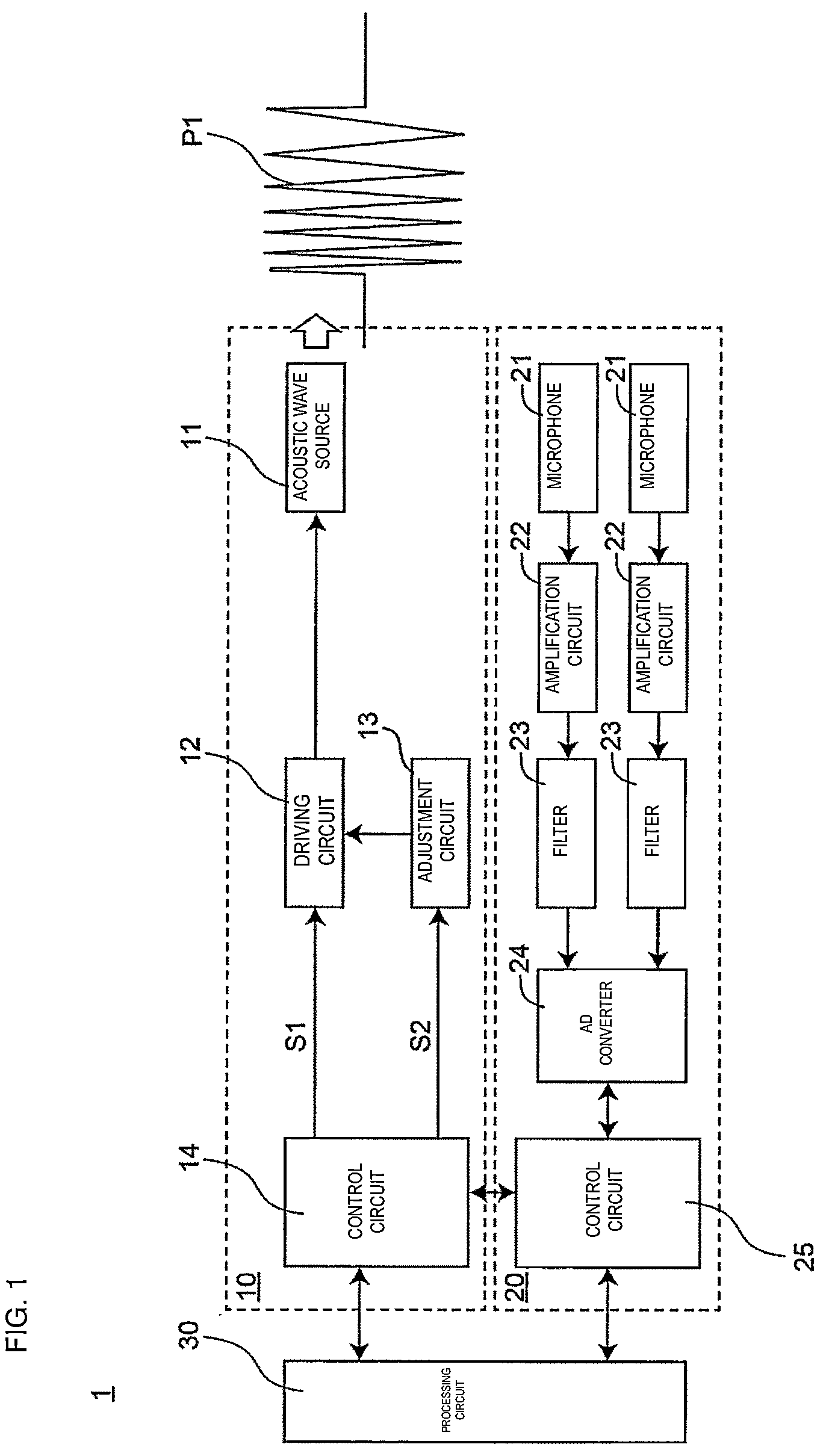
is a block diagram illustrating an exemplary configuration of the object detection system 1 according to a preferred embodiment of the present invention. The object detection system 1 can detect an object in target space using acoustic waves. For example, the object detection system 1 is used in a mobile unit to detect an object, such as an obstacle. Examples of a mobile unit include a vehicle such as an automobile, an unmanned plane such as a drone, and an autonomous mobile robot such as a robot cleaner.
As illustrated in , the object detection system 1 includes an acoustic wave generator 10 to generate an acoustic wave by generating heat upon energization and a processing circuit 30 to perform object detection processing to detect an object in target space using an acoustic wave from the acoustic wave generator 10 . The object detection processing includes wave transmission processing and determination processing. In the wave transmission processing, the acoustic wave generator 10 is controlled to generate a series of acoustic waves P 1 of a time-varying frequency at target sound pressures that are associated with a frequency and correspond to the respective acoustic waves P 1 . In the determination processing, a received-wave signal representing an acoustic wave received by a wave receiver 20 to receive an acoustic wave from target space is acquired from the wave receiver 20 and it is determined whether an object is present in the target space based on the received-wave signal. The target sound pressure is set, based on the frequency characteristics of the sensitivity of the wave receiver 20 to an acoustic wave of a predetermined sound pressure, such that the sensitivity of the wave receiver 20 to an acoustic wave of the target sound pressure is in a predetermined range including a predetermined value. The frequency of a series of the acoustic waves P 1 varies in a predetermined frequency range. The predetermined value is the maximum value of the sensitivity of the wave receiver 20 to the acoustic wave P 1 of a predetermined sound pressure in the predetermined frequency range.
The object detection system 1 illustrated in can set the respective sound pressures of a series of the acoustic waves P 1 of a time-varying frequency to be output from the acoustic wave generator 10 to target sound pressures associated with a frequency. That is, a sound pressure can be set in accordance with the frequency of the acoustic wave P 1 . Accordingly, the influence of frequency characteristics of sensitivity of the wave receiver 20 can be reduced and the decrease in object detection accuracy due to the distortion of a received-wave signal can be reduced or prevented. As described above, object detection accuracy can be improved by using the object detection system 1 .
2. Details
The object detection system 1 will be described below with reference to drawings. As illustrated in , the object detection system 1 includes the acoustic wave generator 10 , the wave receiver 20 , and the processing circuit 30 .
2-1. Acoustic Wave Generator
The acoustic wave generator 10 illustrated in includes an acoustic wave source 11 , a driving circuit 12 , an adjustment circuit 13 , and a control circuit 14 .
The acoustic wave source 11 generates an acoustic wave by generating heat upon energization. More specifically, the acoustic wave source 11 is, for example, a thermal excitation element that generates an acoustic wave by heating air. The acoustic wave source 11 is a thermophone. The acoustic wave source 11 includes, for example, a heating element, a substrate, a pair of electrodes, and a heat-insulating layer. A heating element is a resistance element that generates heat when a current flows therethrough. For example, a heating element is disposed on a substrate such that it is exposed to air. Air around a heating element expands or contracts in response to the change in the temperature of the heating element, so that an air pressure wave, that is, an acoustic wave, is generated. A heat-insulating layer reduces or prevents the transfer of heat from a heating element to a substrate. A pair of electrodes are used to flow a current from the outside of the acoustic wave source 11 to a heating element. One of electrodes in a pair is provided on one side of a heating element, and the other one of the electrodes is provided on the other side of the heating element. The acoustic wave source 11 may have a configuration known in the related art, and the detailed description of the acoustic wave source 11 will be omitted.
is a circuit diagram illustrating an exemplary configuration of the acoustic wave generator 10 . As illustrated in , the acoustic wave source 11 is electrically connected between a direct-current power supply V 1 and the ground.
The direct-current power supply V 1 includes, for example, various power supply circuits and/or a battery. Various power supply circuits include, for example, an AC/DC converter, a DC/DC converter, a regulator, and a battery. The voltage value of the direct-current power supply V 1 is, for example, about 5 V.
The driving circuit 12 supplies power to the acoustic wave source 11 to allow the acoustic wave source 11 to generate an acoustic wave. As illustrated in , the driving circuit 12 includes a capacitor C 1 , a driving switching element T 1 , and a resistor R 1 .
The capacitor C 1 is used to supply power to the acoustic wave source 11 . The capacitor C 1 is electrically connected between the ground and the node between the direct-current power supply V 1 and the acoustic wave source 11 . The capacitor C 1 is, for example, an electrolytic capacitor or a ceramic capacitor.
The driving switching element T 1 is used to drive the acoustic wave source 11 by controlling the supply of power to the acoustic wave source 11 . The driving switching element T 1 is electrically connected between the acoustic wave source 11 and the ground. The driving switching element T 1 is, for example, an n-type MOSFET. When the driving switching element T 1 is in the ON state, power is supplied to the acoustic wave source 11 . Referring to , a current flows from the capacitor C 1 to the acoustic wave source 11 as represented by an arrow A 1 and power is supplied to the acoustic wave source 11 . When the driving switching element T 1 is in the OFF state, power is not supplied to the acoustic wave source 11 . Bringing the driving switching element T 1 into the ON or OFF state allows the acoustic wave source 11 to generate the acoustic wave P 1 . In the present disclosure, “an acoustic wave” is a sinusoidal wave in one period and “a series of acoustic waves” is a sinusoidal wave in a plurality of periods.
The resistor R 1 defines an overcurrent protection element electrically connected between the capacitor C 1 and the direct-current power supply V 1 . The resistor R 1 limits a current that directly flows from the direct-current power supply V 1 to the acoustic wave source 11 . The excessive heat generation of the acoustic wave source 11 can be reduced or prevented by using the resistor R 1 . The resistance value of the resistor R 1 is, for example, from about 50 Ω to about 5 kΩ.
In the driving circuit 12 , a current flows from the capacitor C 1 to the acoustic wave source 11 and power is supplied to the acoustic wave source 11 . Accordingly, the sound pressure of an acoustic wave to be output from the acoustic wave source 11 depends on a voltage V 2 across the capacitor C 1 .
The adjustment circuit 13 adjusts the sound pressure of an acoustic wave to be output from the acoustic wave generator 10 by adjusting the voltage V 2 across the capacitor C 1 in the driving circuit 12 . As illustrated in , the adjustment circuit 13 includes an inductor L 1 , an adjustment switching element T 2 , and a diode D 1 . The inductor L 1 is electrically connected between the direct-current power supply V 1 and the capacitor C 1 . Referring to , the inductor L 1 is electrically connected between the resistor R 1 that is an overcurrent protection element and the direct-current power supply V 1 . The adjustment switching element T 2 is electrically connected in parallel to the series circuit of the inductor L 1 and the direct-current power supply V 1 . The adjustment switching element T 2 is, for example, an n-type MOSFET. The inductor L 1 , the direct-current power supply V 1 , and the adjustment switching element T 2 define a closed loop. When the adjustment switching element T 2 is in the ON state, energy is stored in the inductor L 1 . Referring to , a current flows through the closed loop defined by the direct-current power supply V 1 , the inductor L 1 , and the adjustment switching element T 2 as represented by an arrow A 2 and energy is stored in the inductor L 1 . When the state of the adjustment switching element T 2 is changed from the ON state to the OFF state, an induced electromotive force is generated in the inductor L 1 . As a result, a current flows from the inductor L 1 to the capacitor C 1 as represented by an arrow A 3 and the capacitor C 1 is charged. The adjustment circuit 13 illustrated in can charge the capacitor C 1 and can therefore adjust the voltage V 2 across the capacitor C 1 . Energy to be stored in the inductor L 1 is adjusted in the ON state of the adjustment switching element T 2 . The diode D 1 is electrically connected between the inductor L 1 and the capacitor C 1 . In particular, the anode of the diode D 1 is electrically connected to the inductor L 1 and the cathode of the diode D 1 is electrically connected to the capacitor C 1 . The diode D 1 reduces the possibility that a current flows from the capacitor C 1 to the inductor L 1 and the capacitor C 1 is accidentally discharged.
The control circuit 14 is configured to control the driving circuit 12 and the adjustment circuit 13 . The control circuit 14 includes, for example, an oscillator to output driving signals S 1 and S 2 to be described below. The control circuit 14 is, for example, an integrated circuit such as an FPGA (field-programmable gate array). The control circuit 14 controls the adjustment circuit 13 to set the voltage V 2 across the capacitor C 1 in the driving circuit 12 to a value corresponding to a target sound pressure while controlling the switching of the driving switching element T 1 in the driving circuit 12 to allow the acoustic wave source 11 to generate a series of the acoustic waves P 1 .
The control circuit 14 controls the switching (ON/OFF) of the driving switching element T 1 in the driving circuit 12 . The control circuit 14 performs an operation of causing the acoustic wave source 11 to generate a series of the acoustic waves P 1 by controlling the driving switching element T 1 in the driving circuit 12 .
As illustrated in , the control circuit 14 outputs the driving signal S 1 to control the switching of the driving switching element T 1 . The switching frequency of the driving switching element T 1 corresponds to the frequency of a series of the acoustic waves P 1 . Accordingly, for the generation of a series of the acoustic waves P 1 of a time-varying frequency, the switching frequency of the driving switching element T 1 may be changed with time. The frequency of a series of the acoustic waves P 1 is set to vary in a predetermined frequency range. For example, the predetermined frequency range is from about 20 kHz to about 150 kHz. In this case, the switching frequency of the driving switching element T 1 is also set to vary in this predetermined frequency range.
In the present preferred embodiment, the driving switching element T 1 is, for example, a MOSFET and the driving signal S 1 is input to the gate of the driving switching element T 1 . While the driving signal S 1 is at a high level, the driving switching element T 1 is in the ON state. While the driving signal S 1 is at a low level, the driving switching element T 1 is in the OFF state. The driving signal S 1 is illustrated as a direct-current power supply in .
As illustrated in , the driving signal S 1 is a pulse train signal, the period of which changes with time. Such a signal is a chirp signal. The period of a pulse train of the driving signal S 1 is set in accordance with the switching frequency of the driving switching element T 1 . Referring to , the period of the driving signal S 1 increases with time from T 11 , T 12 , T 13 , . . . . Accordingly, the driving signal S 1 illustrated in is a pulse train, the period of which increases with time. With the driving signal S 1 illustrated in , the switching frequency of the driving switching element T 1 decreases with time. As a result, a series of acoustic waves P of a frequency that decreases with time is output from the acoustic wave source 11 . The length of the driving signal S 1 can be set, for example, from about 5 ms to about 30 ms. The pulse width of the driving signal S 1 is set based on the target duty ratio of the driving switching element T 1 .
The period of the driving signal S 1 includes an ON period T 1 on and an OFF period T 1 off of the driving switching element T 1 . The ON period T 1 on is a period in which the driving switching element T 1 is in the ON state. In the ON period T 1 on, a current flows from the capacitor C 1 to the acoustic wave source 11 and power is supplied to the acoustic wave source 11 . The OFF period T 1 off is a period in which the driving switching element T 1 is in the OFF state. In the OFF period T 1 off, a current does not flow from the capacitor C 1 to the acoustic wave source 11 and power is not supplied to the acoustic wave source 11 .
The control circuit 14 controls the switching (ON/OFF) of the adjustment switching element T 2 in the adjustment circuit 13 . The control circuit 14 performs an operation of adjusting the voltage V 2 across the capacitor C 1 in the driving circuit 12 by controlling the adjustment switching element T 2 in the adjustment circuit 13 . As illustrated in , the control circuit 14 outputs the driving signal S 2 to control the switching of the adjustment switching element T 2 . In the present preferred embodiment, the adjustment switching element T 2 is, for example, a MOSFET and the driving signal S 2 is input to the gate of the adjustment switching element T 2 . The adjustment switching element T 2 is in the ON state while the driving signal S 2 is at the high level. The adjustment switching element T 2 is in the OFF state while the driving signal S 2 is at the low level. Referring to , the driving signal S 2 is illustrated as a direct-current power supply.
In the ON period T 1 on, power is supplied from the capacitor C 1 to the acoustic wave source 11 and the acoustic wave P 1 is output from the acoustic wave source 11 . The control circuit 14 causes the adjustment circuit 13 to adjust the voltage V 2 across the capacitor C 1 before the ON period T 1 on. The control circuit 14 outputs the driving signal S 2 to the adjustment switching element T 2 to control the adjustment circuit 13 to adjust the voltage V 2 across the capacitor C 1 .
Referring to , the driving signal S 2 is a pulse train signal. The driving signal S 2 is synchronized with the driving signal S 1 . Accordingly, the period of the driving signal S 2 is the same or substantially the same as that of the driving signal S 1 . The adjustment switching element T 2 is switched from the ON state to the OFF state before the ON period T 1 on of the driving switching element T 1 in each period. The period of the driving signal S 2 includes an ON period T 2 on and an OFF period T 2 off of the adjustment switching element T 2 . The ON period T 2 on is a period in which the adjustment switching element T 2 is in the ON state. In the ON period T 2 on, a current flows from the direct-current power supply V 1 to the inductor L 1 and energy is stored in the inductor L 1 . The OFF period T 2 off is a period in which the adjustment switching element T 2 is in the OFF state. In the OFF period T 2 off, a current flows from the inductor L 1 to the capacitor C 1 and the capacitor C 1 is charged. Accordingly, the voltage V 2 across the capacitor C 1 can be adjusted using the length of the ON period T 2 on. The longer the ON period T 2 on of the driving signal S 2 , the larger the amount of energy stored in the inductor L 1 in the adjustment circuit 13 .
As illustrated in , the control circuit 14 changes the state of the adjustment switching element T 2 from the ON state to the OFF state before the ON period T 1 on of the driving switching element T 1 . As a result, the voltage V 2 across the capacitor C 1 can be set to a voltage based on the ON period T 2 on of the adjustment switching element T 2 .
2-2. Wave Receiver
The wave receiver 20 receives an acoustic wave and outputs a received-wave signal representing the received acoustic wave to the processing circuit 30 . The wave receiver 20 illustrated in includes a plurality of (for example, two in the drawing) microphones 21 , a plurality of (for example, two in the drawing) amplification circuits 22 , a plurality of (for example, two in the drawing) filters 23 , an AD converter 24 , and a control circuit 25 .
The microphone 21 is an electroacoustic transducer element to convert an acoustic wave into an electric signal. Upon receiving an acoustic wave, the microphone 21 outputs an analog received-wave signal representing the received acoustic wave. The microphone 21 is used to detect an acoustic wave that has been output from the acoustic wave source 11 and then reflected from an object. The amplification circuit 22 amplifies an analog received-wave signal from the microphone 21 and outputs the amplified signal. The filter 23 passes a signal in a pass band including the frequency band of an acoustic wave. The filter 23 is, for example, a bandpass filter. The AD converter 24 converts an analog received-wave signal that has passed through the filter 23 into a digital received-wave signal and outputs the digital received-wave signal to the control circuit 25 . The microphone 21 , the amplification circuit 22 , the filter 23 , and the AD converter 24 may have respective configurations known in the related art, and the detailed description thereof will be omitted.
The control circuit 25 controls the AD converter 24 to cause the AD converter 24 to output a digital received-wave signal to the control circuit 25 . The control circuit 25 outputs a digital received-wave signal output from the AD converter 24 to the processing circuit 30 . The control circuit 25 is, for example, an integrated circuit, such as an FPGA. The control circuit 14 and the control circuit 25 may be integrated into one chip. For example, the control circuit 14 and the control circuit 25 may be provided as a single FPGA.
2-3. Processing Circuit
The processing circuit 30 is a circuit to control the operation of the object detection system 1 . For example, the processing circuit 30 can be defined by a computer system including one or more processors (microprocessors) and one or more memories. One or more processors execute a program to provide the function of the processing circuit 30 .
The processing circuit 30 performs the object detection processing to detect an object in target space using an acoustic wave from the acoustic wave generator 10 . The object detection processing includes the wave transmission processing and the determination processing.
In the wave transmission processing, the acoustic wave generator 10 is controlled to generate a series of the acoustic waves P 1 of a time-varying frequency at target sound pressures that are associated with a frequency and correspond to the respective acoustic waves P 1 . More specifically, in the wave transmission processing, the adjustment circuit 13 adjusts the voltage V 2 across the capacitor C 1 such that the sound pressure of the acoustic wave P 1 from the acoustic wave generator 10 becomes a target sound pressure. The driving switching element T 1 in the driving circuit 12 is driven to cause the acoustic wave source 11 to generate an acoustic wave. In the wave transmission processing, for example, the processing circuit 30 transmits an instruction to the control circuit 14 to cause the control circuit 14 to control the driving circuit 12 and the adjustment circuit 13 . The association between a frequency and a target sound pressure will be described below in “3. Association Between Frequency And Target Sound Pressure.”
In the determination processing, a received-wave signal representing an acoustic wave received by the wave receiver 20 to receive an acoustic wave from target space is acquired from the wave receiver 20 . In the determination processing, for example, a digital received-wave signal is acquired from the wave receiver 20 . In the case where an object is present in target space, an acoustic wave from the target space includes a reflected wave (also referred to as an echo) of an acoustic wave that has been output from the acoustic wave generator 10 and reflected from an object. In the determination processing, it is determined whether an object is present in the target space based on the acquired received-wave signal. In the present preferred embodiment, for example, it is determined in the determination processing that an object is in the target space when the peak value of a cross-correlation function between a transmitted-wave signal representing a series of the acoustic waves P 1 and a received-wave signal is greater than or equal to a threshold value. As the peak of a cross-correlation function, for example, the main lobe of a cross-correlation function is used. In the determination processing, a distance to an object is determined based on a received-wave signal when it is determined that an object is in target space. In the determination processing, for example, a distance to an object is determined based on a time at which the peak of a cross-correlation function between a transmitted-wave signal and a received-wave signal appears using a TOF (time of flight) technique. As described above, the frequency of a series of the acoustic waves P 1 varies with time. In this case, the side lobe of a cross-correlation function can be reduced as compared with the case where a series of the acoustic waves P 1 of a frequency that does not vary with time, that is, a constant frequency, is used. Accordingly, the main lobe of a cross-correlation function can be easily discriminated from the side lobe of the cross-correlation function, and object detection accuracy can be improved. The detection of an object, the measurement of a distance to an object, and the like by the use of an acoustic wave can be performed using techniques known in the related art, and the detailed description thereof will be omitted.
3. Association Between Frequency and Target Sound Pressure
The association between a frequency and a target sound pressure will be described with reference to . is a graph illustrating frequency characteristics of the wave receiver 20 in the object detection system 1 . The frequency characteristics of the wave receiver 20 are determined based on the frequency characteristics of the microphone 21 included in the wave receiver 20 . Referring to , G 1 represents the frequency characteristics of the sensitivity of the wave receiver 20 to an acoustic wave of a predetermined sound pressure. That is, G 1 represents the change in sensitivity of the wave receiver 20 when the sound pressure of an acoustic wave is constant and the frequency of the acoustic wave varies. As is apparent from G 1 , the sensitivity at about 60 kHz is lower than that at about 40 kHz. Since G 1 is obtained when an acoustic wave has a constant predetermined sound pressure, the adjustment of a sound pressure of the acoustic wave P 1 based on the frequency characteristics of the microphone 21 results in the adjustment of sensitivity of the wave receiver 20 . From this point, a target sound pressure is set based on the frequency characteristics of the sensitivity of the wave receiver 20 to an acoustic wave of a predetermined sound pressure. A target sound pressure is set such that the sensitivity of the wave receiver 20 to an acoustic wave of a target sound pressure is in a predetermined range including a predetermined value Vs. As described above, the frequency of a series of the acoustic waves P 1 varies in a predetermined frequency range. The predetermined frequency range is, for example, the range of about 40 kHz to about 80 kHz. Referring to , the sensitivity of the wave receiver 20 is below the predetermined value Vs in the range of about 40 kHz to about 80 kHz. As is represented by G 2 in , it is preferable that a target sound pressure is set such that the sensitivity of the wave receiver 20 coincides with the predetermined value Vs. In reality, a target sound pressure may be set such that the sensitivity of the wave receiver 20 is in a predetermined range including the predetermined value Vs. The predetermined value Vs is the maximum value of the sensitivity of the wave receiver 20 to the acoustic wave P 1 of a predetermined sound pressure in a predetermined frequency range. As a result, high sensitivity can be achieved in the predetermined frequency range. In this case, the target sound pressure of an acoustic wave of a frequency at which the sensitivity of the wave receiver 20 to an acoustic wave of a predetermined sound pressure is less than a predetermined value is set to be higher than the predetermined sound pressure. The predetermined range may be set such that the predetermined value Vs is between the upper limit and the median value of the predetermined range. That is, the upper limit of the predetermined value Vs may be greater than or equal to a predetermined value, and the median value of the predetermined range may be less than or equal to the predetermined value. In the present preferred embodiment, the upper limit of a predetermined range is the predetermined value Vs (that is, the maximum value of the sensitivity of the wave receiver 20 to the acoustic wave P 1 of a predetermined sound pressure in a predetermined frequency range). The lower limit of the predetermined range is less than or equal to the predetermined value and is greater than the minimum value of the sensitivity of the wave receiver 20 to the acoustic wave P 1 of a predetermined sound pressure in the predetermined frequency range. The lower limit of the predetermined range is, for example, Vs−k·d(0≤k<1) where d is the difference between the maximum value and the minimum value of the sensitivity of the wave receiver 20 to the acoustic wave P 1 of a predetermined sound pressure in a predetermined frequency range. When k is less than or equal to about 0.5, the range of the change in the sensitivity of the wave receiver 20 to an acoustic wave of a target sound pressure in a predetermined frequency range can be set to be smaller than or equal to a half of the range of the change in the sensitivity of the wave receiver 20 to an acoustic wave of a predetermined sound pressure in the predetermined frequency range. That is, the predetermined range is narrower than the range of the change in the sensitivity of the wave receiver 20 to an acoustic wave of a predetermined sound pressure in a predetermined frequency range. As a result, the influence of frequency characteristics of sensitivity of the wave receiver 20 can be reduced and the decrease in object detection accuracy due to the distortion of a received-wave signal can be reduced or prevented. This leads to improvement of object detection accuracy. The predetermined range may be the range of, for example, about ±10% of the predetermined value Vs. That is, for example, the lower limit of the predetermined range may be about 0.9×Vs and the upper limit of the predetermined range may be about 1.1×Vs.
Thus, by making the association between a frequency and a target sound pressure, the influence of frequency characteristics of sensitivity of the wave receiver 20 can be reduced and the decrease in object detection accuracy due to the distortion of a received-wave signal can be reduced or prevented. Consequently, object detection accuracy can be improved.
4. Advantageous Effect, etc.
The object detection system 1 described above includes the acoustic wave generator 10 to generate an acoustic wave by generating heat upon energization and the processing circuit 30 to perform object detection processing to detect an object in target space using an acoustic wave from the acoustic wave generator 10 . The object detection processing includes the wave transmission processing in which the acoustic wave generator 10 is controlled to generate a series of the acoustic waves P 1 of a time-varying frequency at target sound pressures that are associated with a frequency and correspond to the respective acoustic waves P 1 and the determination processing in which a received-wave signal representing an acoustic wave received by the wave receiver 20 for receiving an acoustic wave from target space is acquired from the wave receiver 20 and it is determined whether an object is present based on the received-wave signal. With this configuration, object detection accuracy can be improved. The target sound pressure is set, based on the frequency characteristics of the sensitivity of the wave receiver 20 to an acoustic wave of a predetermined sound pressure, such that the sensitivity of the wave receiver 20 to an acoustic wave of the target sound pressure is in a predetermined range including a predetermined value. The frequency of a series of the acoustic waves P 1 varies in a predetermined frequency range. The predetermined value is the maximum value of the sensitivity of the wave receiver 20 to the acoustic wave P 1 of a predetermined sound pressure in the predetermined frequency range.
In the object detection system 1 , the upper limit of the predetermined range is greater than or equal to the predetermined value and the median value of the predetermined range is equal to or less than the predetermined value. With this configuration, object detection accuracy can be improved.
In the object detection system 1 , the lower limit of the predetermined range is less than the predetermined value and is greater than the minimum value of the sensitivity of the wave receiver 20 to the acoustic wave P 1 of a predetermined sound pressure in the predetermined frequency range. With this configuration, object detection accuracy can be improved.
In the object detection system 1 , the upper limit of the predetermined range is the predetermined value. With this configuration, object detection accuracy can be improved.
In the object detection system 1 , the target sound pressure of an acoustic wave of a frequency at which the sensitivity of the wave receiver 20 to an acoustic wave of a predetermined sound pressure is less than the predetermined value is higher than the predetermined sound pressure. With this configuration, object detection accuracy can be improved.
In the object detection system 1 , the predetermined range is, for example, the range of about ±10% of the predetermined value Vs. With this configuration, object detection accuracy can be improved.
The object detection system 1 includes the acoustic wave generator 10 to generate an acoustic wave by generating heat upon energization and the processing circuit 30 to perform object detection processing to detect an object in target space using an acoustic wave from the acoustic wave generator 10 . The object detection processing includes the wave transmission processing in which the acoustic wave generator 10 is controlled to generate a series of the acoustic waves P 1 of a time-varying frequency at target sound pressures that are associated with a frequency and correspond to the respective acoustic waves P 1 and the determination processing in which a received-wave signal representing an acoustic wave received by the wave receiver 20 to receive an acoustic wave from target space is acquired from the wave receiver 20 and it is determined whether an object is present based on the received-wave signal. The frequency of a series of the acoustic waves P 1 varies in a predetermined frequency range. The target sound pressure is set, based on the frequency characteristics of the sensitivity of the wave receiver 20 to an acoustic wave of a predetermined sound pressure, such that the sensitivity of the wave receiver 20 to an acoustic wave of the target sound pressure coincides with a predetermined value. The predetermined value is the maximum value of the sensitivity of the wave receiver 20 to the acoustic wave P 1 of a predetermined sound pressure in the predetermined frequency range. With this configuration, object detection accuracy can be improved.
In the object detection system 1 , it is determined in the determination processing that an object is present when the peak value of a cross-correlation function between a transmitted-wave signal representing a series of the acoustic waves P 1 and a received-wave signal is greater than or equal to a threshold value. With this configuration, object detection accuracy can be improved.
In the object detection system 1 , a distance to an object is determined based on a received-wave signal when it is determined that an object is present in the determination processing. With this configuration, a distance to an object can be obtained.
In the object detection system 1 , the acoustic wave generator 10 includes the driving circuit 12 including the capacitor C 1 charged by the direct-current power supply V 1 and the driving switching element T 1 to supply power from the capacitor C 1 to the acoustic wave source 11 to generate an acoustic wave by generating heat upon energization and the adjustment circuit 13 to adjust the sound pressure of an acoustic wave to be output from the acoustic wave generator 10 by adjusting the voltage V 2 across the capacitor C 1 in the driving circuit 12 . In the wave transmission processing, the adjustment circuit 13 adjusts the voltage V 2 across the capacitor C 1 such that the sound pressure of an acoustic wave to be output from the acoustic wave generator 10 becomes a target sound pressure, and the driving switching element T 1 in the driving circuit 12 is driven to cause the acoustic wave source 11 to generate an acoustic wave. With this configuration, the sound pressure of an acoustic wave to be output from the acoustic wave generator 10 can be easily adjusted.
In the object detection system 1 , the adjustment circuit 13 includes the inductor L 1 electrically connected between the direct-current power supply V 1 and the capacitor C 1 and the adjustment switching element T 2 electrically connected in parallel to a series circuit of the inductor L 1 and the direct-current power supply V 1 . The adjustment circuit 13 adjusts the voltage V 2 across the capacitor C 1 in the ON period T 2 on of the adjustment switching element T 2 . With this configuration, a simple circuit configuration can be obtained.
In the object detection system 1 , the adjustment circuit 13 includes the diode D 1 , the anode of which is electrically connected to the inductor L 1 and the cathode of which is electrically connected to the capacitor C 1 . With this configuration, the possibility that a current flows from the capacitor C 1 to the inductor L 1 and the capacitor C 1 is accidentally discharged can be reduced or prevented.
In the object detection system 1 , the state of the adjustment switching element T 2 is changed from the ON state to the OFF state before the ON period T 1 on of the driving switching element T 1 . With this configuration, the sound pressure of an acoustic wave can be easily adjusted.
In the object detection system 1 , the switching frequency of the driving switching element T 1 is, for example, greater than or equal to about 20 kHz. With this configuration, object detection accuracy can be improved.
Modification
Preferred embodiments of the present invention are not limited to the above-described preferred embodiment. The above-described preferred embodiment can be variously modified depending on design and the like as long as the advantageous effects of the present invention can be achieved. Modifications of the above-described preferred embodiment will be described below. The modifications to be described below can be applied in appropriate combination.
1. First Modification
is a circuit diagram illustrating an exemplary configuration of an acoustic wave generator 10 A that is a first modification of a preferred embodiment of the present invention. The acoustic wave generator 10 A includes the acoustic wave source 11 , a driving circuit 12 A, and an adjustment circuit 13 A. The acoustic wave generator 10 A includes the control circuit 14 as in the acoustic wave generator 10 , but the illustration of the control circuit 14 is omitted in .
The driving circuit 12 A includes the driving switching element T 1 to supply power from a predetermined capacitor to the acoustic wave source 11 to generate an acoustic wave by generating heat upon energization. The driving switching element T 1 is used to control the supply of power to the acoustic wave source 11 . The driving switching element T 1 is connected between the acoustic wave source 11 and the ground. When the driving switching element T 1 is in the ON state, power is supplied to the acoustic wave source 11 . When the driving switching element T 1 is in the OFF state, power is not supplied to the acoustic wave source 11 . Bringing the driving switching element T 1 into the ON or OFF state allows the acoustic wave source 11 to generate an acoustic wave. The driving switching element T 1 is, for example, an n-type MOSFET.
The adjustment circuit 13 A adjusts the sound pressure of an acoustic wave to be output from the acoustic wave generator 10 by selecting, as a predetermined capacitor, at least one of a plurality of (for example, three in the drawing) capacitors C 1 - 1 to C 1 - 3 (hereinafter collectively referred to as C 1 ) charged by a plurality of (for example, three in the drawing) direct-current power supplies V 1 - 1 to V 1 - 3 (hereinafter collectively referred to as V 1 ) of different voltages, respectively. As illustrated in , the adjustment circuit 13 A includes the plurality of capacitors C 1 - 1 to C 1 - 3 and a switching circuit 131 .
The plurality of capacitors C 1 - 1 to C 1 - 3 are charged by the plurality of direct-current power supplies V 1 - 1 to V 1 - 3 of different voltages, respectively. The capacitor C 1 is used to supply power to the acoustic wave source 11 . The capacitor C 1 is electrically connected between the ground and the node between the direct-current power supply V 1 and the acoustic wave source 11 . The capacitor C 1 is charged by the direct-current power supply V 1 . The capacitor C 1 is, for example, an electrolytic capacitor or a ceramic capacitor.
The switching circuit 131 selects a power supply source for the acoustic wave source 11 from among the plurality of capacitors C 1 . More specifically, the switching circuit 131 electrically connects at least one of the plurality of capacitors C 1 to the acoustic wave source 11 to cause the acoustic wave generator 10 A to generate an acoustic wave at a target sound pressure associated with a frequency. For example, a plurality of sets of the capacitor C 1 and the direct-current power supply V 1 are used to obtain target sound pressures associated with different frequencies.
The switching circuit 131 includes a plurality of (for example, three in the drawing) switches SW 1 - 1 to SW 1 - 3 (hereinafter collectively referred to as SW 1 ) as illustrated in . The plurality of switches SW 1 - 1 to SW 1 - 3 are electrically connected between the acoustic wave source 11 and the plurality of capacitors C 1 - 1 to C 1 - 3 , respectively. In the switching circuit 131 , one of the plurality of switches SW 1 - 1 to SW 1 - 3 is turned on and the remains of them are turned off. One of the plurality of capacitors C 1 - 1 to C 1 - 3 is therefore electrically connected to the acoustic wave source 11 .
The control circuit 14 controls the driving circuit 12 A and the switching circuit 131 in the adjustment circuit 13 A. To cause the acoustic wave generator 10 to generate a series of the acoustic waves P 1 of a time-varying frequency at target sound pressures that are associated with a frequency and correspond to the respective acoustic waves P 1 , the control circuit 14 electrically connects at least one of the plurality of capacitors C 1 to the acoustic wave source 11 by controlling the switch SW 1 in the switching circuit 131 .
In the case where the object detection system 1 includes the acoustic wave generator 10 A, the processing circuit 30 controls the control circuit 14 in the acoustic wave generator 10 A to perform wave transmission processing to be described below. In the wave transmission processing, the adjustment circuit 13 A selects, as a predetermined capacitor, the capacitor C 1 corresponding to a target sound pressure from among the plurality of capacitors C 1 and the driving switching element T 1 in the driving circuit 12 A is driven to cause the acoustic wave source 11 to generate an acoustic wave.
Thus, the object detection system 1 can set the respective sound pressures of a series of the acoustic waves P 1 of a time-varying frequency to be output from the acoustic wave generator 10 A to target sound pressures associated with a frequency. That is, a sound pressure can be set in accordance with the frequency of the acoustic wave P 1 . Accordingly, the influence of frequency characteristics of sensitivity of the wave receiver 20 can be reduced and the decrease in object detection accuracy due to the distortion of a received-wave signal can be reduced or prevented. As described above, object detection accuracy can be improved by using the object detection system 1 .
In the object detection system 1 described above, the acoustic wave generator 10 A includes the driving circuit 12 A including the driving switching element T 1 to supply power from the predetermined capacitor C 1 to the acoustic wave source 11 to generate an acoustic wave by generating heat upon energization and the adjustment circuit 13 A to adjust the sound pressure of an acoustic wave to be output from the acoustic wave generator 10 A by selecting, as the predetermined capacitor C 1 , at least one of the plurality of capacitors C 1 charged by the plurality of respective direct-current power supplies V 1 of different voltages. In the wave transmission processing, the adjustment circuit 13 A selects, as the predetermined capacitor C 1 , the capacitor C 1 corresponding to a target sound pressure from among the plurality of capacitors C 1 and the driving switching element T 1 in the driving circuit 12 A is driven to cause the acoustic wave source 11 to generate an acoustic wave. With this configuration, the sound pressure of an acoustic wave to be output from the acoustic wave generator 10 A can be easily adjusted.
2. Second Modification
is a circuit diagram illustrating an exemplary configuration of an acoustic wave generator 10 B that is a second modification of a preferred embodiment of the present invention. The acoustic wave generator 10 B includes a plurality of (for example, three in the drawing) acoustic wave sources 11 - 1 to 11 - 3 (hereinafter collectively referred to as 11 ), the driving circuit 12 , and an adjustment circuit 13 B. The acoustic wave generator 10 B includes the control circuit 14 as in the acoustic wave generator 10 , but the illustration of the control circuit 14 is omitted in .
The plurality of acoustic wave sources 11 - 1 to 11 - 3 are electrically connected between the direct-current power supply V 1 and the ground. As illustrated in , the plurality of acoustic wave sources 11 - 1 to 11 - 3 are connected in parallel.
The driving circuit 12 includes the capacitor C 1 charged by the direct-current power supply V 1 and the driving switching element T 1 to supply power from the capacitor C 1 to the predetermined acoustic wave source 11 . The predetermined acoustic wave source 11 is selected from among the plurality of acoustic wave sources 11 - 1 to 11 - 3 . The driving circuit 12 supplies power to the predetermined acoustic wave source 11 to cause the predetermined acoustic wave source 11 to generate an acoustic wave. The driving circuit 12 includes the resistor R 1 . The resistor R 1 defines an overcurrent protection element electrically connected between the capacitor C 1 and the direct-current power supply V 1 .
The adjustment circuit 13 B adjusts the sound pressure of an acoustic wave to be output from the acoustic wave generator 10 B by selecting, as the predetermined acoustic wave source 11 , at least one of the plurality of acoustic wave sources 11 - 1 to 11 - 3 . As illustrated in , the adjustment circuit 13 B selects a destination to which power from the capacitor C 1 is to be supplied from among the plurality of acoustic wave sources 11 - 1 to 11 - 3 . More specifically, the adjustment circuit 13 B electrically connects at least one of the plurality of acoustic wave sources 11 - 1 to 11 - 3 to the capacitor C 1 to cause the acoustic wave generator 10 B to generate an acoustic wave at a target sound pressure associated with a frequency. The plurality of acoustic wave sources 11 are used to obtain target sound pressures associated with different frequencies.
As illustrated in , the adjustment circuit 13 B includes a plurality of (three in the drawing) switches SW 2 - 1 to SW 2 - 3 (hereinafter collectively referred to as SW 2 ). The plurality of switches SW 2 - 1 to SW 2 - 3 are electrically connected between the plurality of acoustic wave sources 11 - 1 to 11 - 3 and the capacitor C, respectively. In the adjustment circuit 13 B, one of the plurality of switches SW 2 - 1 to SW 2 - 3 is turned on and the remaining ones of them are turned off. One of the plurality of acoustic wave sources 11 - 1 to 11 - 3 is therefore electrically connected to the capacitor C 1 .
The control circuit 14 controls the driving circuit 12 and the adjustment circuit 13 B. To cause the acoustic wave generator 10 B to generate an acoustic wave at a target sound pressure associated with a frequency, the control circuit 14 electrically connects at least one of the plurality of acoustic wave sources 11 to the capacitor C 1 by controlling the switch SW 2 in the adjustment circuit 13 B.
In the case where the object detection system 1 includes the acoustic wave generator 10 B, the processing circuit 30 controls the control circuit 14 in the acoustic wave generator 10 B to perform wave transmission processing to be described below. In the wave transmission processing, the adjustment circuit 13 B selects, as the predetermined acoustic wave source 11 , the acoustic wave source 11 corresponding to a target sound pressure from among the plurality of acoustic wave sources 11 and the driving switching element T 1 in the driving circuit 12 is driven to cause the predetermined acoustic wave source 11 to generate an acoustic wave.
Thus, the object detection system 1 can set the respective sound pressures of a series of the acoustic waves P 1 of a time-varying frequency to be output from the acoustic wave generator 10 B to target sound pressures associated with a frequency. That is, a sound pressure can be set in accordance with the frequency of the acoustic wave P 1 . Accordingly, the influence of frequency characteristics of sensitivity of the wave receiver 20 can be reduced and the decrease in object detection accuracy due to the distortion of a received-wave signal can be reduced or prevented. As described above, object detection accuracy can be improved by using the object detection system 1 .
In the object detection system 1 described above, the acoustic wave generator 10 B includes the plurality of acoustic wave sources 11 to generate acoustic waves of different sound pressures by generating heat upon energization, the driving circuit 12 including the capacitor C 1 charged by the direct-current power supply V 1 and the driving switching element T 1 to supply power from the capacitor C 1 to the predetermined acoustic wave source 11 , and the adjustment circuit 13 B to adjust the sound pressure of an acoustic wave to be output from the acoustic wave generator 10 B by selecting, as the predetermined acoustic wave source 11 , at least one of the plurality of acoustic wave sources 11 . In the wave transmission processing, the adjustment circuit 13 B selects, as the predetermined acoustic wave source 11 , the acoustic wave source 11 corresponding to a target sound pressure from among the plurality of acoustic wave sources 11 and the driving switching element T 1 in the driving circuit 12 is driven to cause the predetermined acoustic wave source 11 to generate an acoustic wave. With this configuration, the sound pressure of an acoustic wave to be output from the acoustic wave generator 10 B can be easily adjusted.
3. Other Modifications
The frequency of a series of the acoustic waves P decreases with time in the above-described preferred embodiment, but may increase with time.
In a modification of a preferred embodiment of the present invention, the predetermined value does not necessarily have to be the representative value of the sensitivity of the wave receiver 20 to an acoustic wave of a predetermined sound pressure in a predetermined frequency range. That is, the predetermined value may be a desired value. However, when the predetermined value is the representative value of the sensitivity of the wave receiver 20 to an acoustic wave of a predetermined sound pressure in a predetermined frequency range, the difference between the predetermined sound pressure and a target sound pressure can be reduced and the setting of a target sound pressure can be easily performed.
In a modification of a preferred embodiment of the present invention, the predetermined range may be set to achieve the reduction in the influence of frequency characteristics of sensitivity of the wave receiver 20 in consideration of the frequency characteristics of the sensitivity of the wave receiver 20 to an acoustic wave of a predetermined sound pressure.
In the first modification, the number of the direct-current power supplies V 1 and the number of the capacitors C 1 are not particularly limited. The adjustment circuit 13 A may connect the two or more capacitor C 1 to the acoustic wave source 11 as needed. The plurality of capacitors C 1 are connected in parallel to the acoustic wave source 11 in the first modification, but may be connected in series to the acoustic wave source 11 . In this case, a voltage to be applied to the acoustic wave source 11 can be adjusted by causing the switching circuit 131 to change the number of series connections of the plurality of capacitors C 1 . The configuration in the first modification is also applicable to the acoustic wave generator 10 and the acoustic wave generator 10 B.
In the second modification, the number of the acoustic wave sources 11 are not particularly limited. The adjustment circuit 13 B may connect the two or more acoustic wave sources 11 to the capacitor C 1 as needed. The plurality of acoustic wave sources 11 are connected in parallel to the capacitor C 1 in the second modification, but may be connected in series to the capacitor C 1 . In this case, a sound pressure can be adjusted by causing the adjustment circuit 13 B to change the number of series connections of the plurality of acoustic wave sources 11 . The configuration in the second modification is also applicable to the acoustic wave generator 10 and the acoustic wave generator 10 A.
In a modification, another overcurrent protection element may be used instead of the resistor R 1 . Examples of an overcurrent protection element include a current fuse, a fuse resistor, and bimetal. An overcurrent protection element does not necessarily have to be provided.
Preferred embodiments of the present invention are applicable to an acoustic wave generator. Specifically, preferred embodiments of the present invention are applicable to an object detection system to detect an object using an acoustic wave.
While preferred embodiments of the present invention have been described above, it is to be understood that variations and modifications will be apparent to those skilled in the art without departing from the scope and spirit of the present invention. The scope of the present invention, therefore, is to be determined solely by the following claims.
Figures (6)
Citations
This patent cites (14)
- US6572546
- US9838802
- US10444350
- US2016/0238700
- US2017/0227640
- US2018/0031701
- US2019/0276030
- US2020/0225346
- US2020/0304924
- US2021/0231799
- US2018105703
- US2019066192
- US2019159400
- US2020004609