Capacitive Filling Level Probe Without Dead Zone
Abstract
A filling level measuring device, a method for capacitive filling level measurement of filling material in a container that includes a counter electrode integrated therein using a filling level probe, and a method for calibrating a filling level probe, that includes introducing the filling level probe into the container. The filling level probe has first and second spaced apart electrodes extending successively and substantially parallel to the counter electrode, thereby defining a measurement path. The level probe is operable in a first, second, or third measurement mode, by switching between a measurement potential or a shielding potential that can each be applied to the first and second electrodes, while a counter electrode potential is applied to the counter electrode. For capacitive filling level measurement, relative capacitance changes measured with a calibrated level probe in each measurement mode compared to an empty container, are used.
Claims (5)
1. A filling level measuring device for capacitive filling level measurement of filling material in the form of liquids and/or bulk materials in a container that has a counter electrode integrated in the container, comprising: measuring electronics and a filling level probe connectable to the measuring electronics; wherein the filling level probe includes a first electrode and a second electrode which have to be introduced into the container for the filling level measurement and which, in their introduced state, extend into the container one after the other in alignment along their longitudinal extension and spaced apart from each other and substantially parallel to the counter electrode; so that: when the container is being filled, the first electrode will first be covered by filling material before the second electrode is at least partially covered by filling material, and a measurement section is defined by the entire range between a first end of the first electrode remote from the second electrode and a second end of the second electrode remote from the first electrode; wherein the measuring electronics are configured to provide a measurement potential, a shielding potential, and a counter electrode potential, and comprise a switching unit including a first switch that is electrically connectable to the first electrode and a second switch that is electrically connectable to the second electrode; wherein, for operating the filling level measuring device, the switching unit is operable to set a first, second, or third measurement mode, by having the first switch adapted to switch over between the measurement potential or the shielding potential that are configured to be applied to the first electrode, and by having the second switch adapted to switch over between the measurement potential or the shielding potential that are configured to be applied to the second electrode, and wherein in the first measurement mode the measurement potential is applied to the first electrode and the shielding potential to the second electrode, in the second measurement mode the shielding potential is applied to the first electrode and the measurement potential to the second electrode, and in the third measurement mode the measurement potential is applied to the first and second electrodes, and in each of the three measurement modes the counter electrode potential is applied to the counter electrode; and wherein the measuring electronics comprise an evaluation unit that is electrically connected to the switching unit and adapted to control the switching unit and to calculate the filling level on the basis of relative changes in capacitance compared to a completely empty container as measured by the measurement electronics in each of the three measurement modes.
Show 4 dependent claims
2. The filling level measuring device of claim 1 , wherein the first electrode has a first length and the second electrode has a second length, such that the second length is greater than the first length or at least equal to the first length.
3. The filling level measuring device of claim 1 , wherein: the filling level probe comprises a substrate on which the first and second electrodes are attached, wherein the substrate is in the form of a rod or circuit board and is surrounded by at least one electrically insulating material; and/or the filling level probe is mounted substantially vertically in the container, in or on the container wall.
4. The filling level measuring device of claim 1 , wherein the first electrode and/or the second electrode are in the form of individual rings or plates with an insulator.
5. The filling level measuring device of claim 1 , wherein the filling level probe has a shielding electrode which is arranged between the first end of the first electrode and a bottom of the container.
Full Description
Show full text →
CROSS-REFERENCE TO RELATED APPLICATIONS
This application claims the benefit of foreign priority of European Patent Application No. 21 190 413.1, filed Aug. 9, 2021, the entire disclosure of which is incorporated herein by reference.
FIELD
The present invention relates to a filling level measuring device and to a method for capacitive filling level measurement of filling material in the form of liquids and/or bulk materials in a container which comprises a counter electrode integrated in the container. The invention furthermore includes a method for calibrating a filling level probe for a capacitive filling level measurement as mentioned above.
BACKGROUND
Capacitive filling level measurements are known in the prior art and are based on detecting a filling level, i.e. a filling height of liquids and/or bulk materials in a container by using a capacitive sensor to determine changes in capacitance caused by the filling of the container with a filling material or by emptying the container of filling material. For this purpose, measurement probes or sensors are employed, which are introduced into the mostly conductive container substantially vertically, and which have a measurement electrode. A capacitor arrangement is defined between the measurement electrode and the container wall as a counter electrode or a counter electrode arranged on the container wall substantially parallel to the measurement electrode. As the filling level of the filling material in the container increases or decreases, the capacitance value of the capacitor arrangement will increase or decrease. Hence, the capacitance value of the capacitor arrangement is a measure of the filling level or filling height of a filling material in the container and is used to calculate the filling level in the context of capacitive filling level measurements.
If the container is empty or filled with air, a minimum capacitance value results as a reference value (basic capacitance C 0 ), which ideally can be regarded to be constant. In fact, parasitic influences such as changes in humidity do result in deviations from this assumption of constancy. However, such deviations from the reference value are usually negligible compared to the changes in capacitance to be considered below.
If there is a filling material in the container, the capacitance of the capacitor arrangement will change as a function of the filling level of the filling material, the geometry of the capacitor arrangement, in particular the spacing between the capacitor plates, and the dielectric constant ε r of the respective filling material. The terms dielectric constant, permittivity, and relative permittivity have the same meaning and are used synonymously within the context of the present invention. A maximum change in capacitance that can be measured with the measuring probe will result at a maximum filling level of the filling material in the container, which is usually predetermined.
In order to obtain a linear dependency between the change in capacitance and the filling level of a filling material in the container, the cross section of the container and the diameter of the measuring probe must be consistent along the measurement section, i.e. within the range of measurement in the height direction of the container. Therefore, often, measurement arrangements are used in which the measuring probes are arranged inside a conductive tube or cylindrical container, so that a measurement arrangement in the form of a cylindrical capacitor is resulting. This has the advantage of having only slight field distortions or non-linearities occurring at the ends of the measuring probe, so that a falsification of the measured values at the start and end of the measuring range is fairly small and can usually be ignored.
The dependency on the permittivity of the filling materials is a challenge for capacitive filling level measurements, since the permittivity of a material can only be considered to be a constant material parameter in a few applications. What leads to significant deviations in the permittivity of a filling material, besides a change of the filling material and a mixing of different filling materials, are changes in the bulk density, changes in the moisture content, and inhomogeneities, among other things. Consequently, for capacitive filling level measurements, a so-called empty calibration and a so-called full calibration must usually first be performed for metrologically identifying the respective end values. Usually, the empty calibration is performed when the container is completely empty, but in some measurement arrangements it is performed at a predefined filling level. A full calibration corresponds to a container filled to a predefined maximum level. Mostly, the container has to be filled and emptied several times for the empty calibration and the full calibration, which is quite time-consuming. When the filling material changes, the empty calibration and full calibration must be performed again, since the end value identified in full calibration depends on the permittivity of the filling material.
In order to mitigate the aforementioned drawbacks, measurement arrangements and measuring methods for capacitively determining a filling level with compensation for changes in permittivity have already been used in the prior art.
For example, DE 195 28 384 C2 discloses a capacitive measuring device comprising two measurement electrodes arranged one above the other on a sensor, for continuous filling level measurement for media having different dielectric constants using the capacitive voltage divider principle, also known as the three electrode measuring principle. However, a permittivity-independent measurement is only possible within the range of the upper measurement electrode. In addition, a shielding electrode is required between the two measurement electrodes, which constitutes a dead zone with regard to the filling level measurement.
Applicant's DE 197 49 884 C1 describes a capacitive measuring device that is improved compared to DE 195 28 384 C2, comprising a reference electrode as the lower measurement electrode, an upper measurement electrode, and shielding electrodes which delimit the lower and upper measurement electrodes and decouple them from one another, but also constitute a dead zone for level measurement. Compared to DE 195 28 384 C2, improved calibration of a container in the empty state is described using the reference electrode.
WO 00/26619 A1 discloses a method for filling level measurement based on a first plate capacitor arrangement and a second plate capacitor arrangement each having a measurement electrode and a counter electrode as the measurement arrangement. While the first plate capacitor arrangement extends over at least part of the filling height of the container and is intended to determine the current filling level, the second plate capacitor arrangement serves to determine a reference value and is completely covered by filling material up to a known filling level mark to determine the dielectric constant of the filling material. If the current level falls below the known filling level mark, the dielectric constant determined most recently is used to determine the current filling level. However, for determining the current filling level, the geometry of the two plate capacitor arrangements must always be known, the capacitor plates have to be spaced apart far enough to avoid mutual field interference, and the filling material must be located between the two capacitor plates. Moreover, the current filling level can only be determined once the second plate capacitor arrangement has been completely covered by filling material.
A similar approach is also pursued by DE 102 51 842 A1 which discloses a device and a method for capacitive filling level measurement by comparing a measurement capacitance with a reference capacitance, with a closed control loop being used as the measurement circuit. The reference capacitance has a known geometry and is always completely surrounded by filling material. Based thereon, a relative permittivity ε r of the respective filling material is determined, which in turn is used to determine the filling level.
EP 3 457 095 A1 relates to a capacitive level sensor and a method for a capacitance measurement of the filling level of a filling material in a container including compensation for environmental influences. The filling level sensor comprises a measuring probe with at least one measurement electrode for determining a capacitance and for calculating a filling level, and at least one reference electrode arranged in the interior of the measuring probe for a capacitance measurement independent of the filling level to thus compensate for environmental influences on the capacitance measurement at the measurement electrode, such as temperature and humidity. The measuring probe may comprise a plurality of segments which are arranged one above the other along their longitudinal extension, each one having a measurement electrode and a reference electrode.
Applicant's EP 2 735 851 A1 discloses a method and a device for capacitive filling level measurement using a measurement circuit and a filling level probe. A first electrode arrangement functioning as a measurement electrode defines a measurement section and is formed on the filling level probe. A second electrode arrangement functioning as a boundary electrode is arranged at least at one end of this measurement section. Preferably, such a second electrode arrangement is provided at both end points of the measurement section, each defining a boundary of the measurement section. The measurement circuit includes a differential circuit, so as to produce a differential signal of a change in capacitance between a respective boundary electrode and a counter electrode, for example the container wall, and a change in capacitance between a measurement electrode and this counter electrode, in order to compensate for the systematic falsifications caused by changes in permittivity of the filling material.
WO 2020/113283 A1 discloses a capacitive sensor system and a method for detecting an object based on the identification of material properties, e.g. the dipole moment or permittivity, of this object. The capacitive sensor system comprises a capacitive sensing pad, a conductive discriminating pad in proximity to the sensing pad, a switch, a capacitance measurement circuit, and a controller. The switch selectively couples the discrimination pad to a voltage potential of the capacitive sensing pad or to a ground potential. The capacitance measurement circuit detects a capacitance value of the capacitive sensing pad. The controller is operable to measure the capacitance value of the capacitive sensing pad when the discriminating pad is coupled to the capacitive sensing pad voltage potential or to ground potential. In order to be able to determine the material properties, such as permittivity, of an object, the capacitive sensor pad has to be completely covered by the object to be identified.
SUMMARY
In the light of the prior art background mentioned above, it is an object of the invention to provide a filling level measuring device and a method for capacitive filling level measurement of filling material, which improves and simplifies the determination of a filling level based on measured capacitances compared to the prior art mentioned above, and which in particular is substantially continuous, independent of the permittivity and does not have any dead zones along the measurement section.
Accordingly, the invention proposes a filling level measuring device for capacitive filling level measurement of filling material in the form of liquids and/or bulk materials in a container that has a counter electrode integrated in the container, the measuring device comprising measuring electronics and a filling level probe connectable to the measuring electronics. The filling level probe has a first electrode and a second electrode provided thereon, which have to be introduced into the container for the filling level measurement and which, in their introduced state, extend into the container one after the other in alignment along their longitudinal extension and spaced apart from each other and substantially parallel to the counter electrode, so that when the container is being filled, the first electrode will first be covered by filling material before the second electrode is at least partially covered by filling material. The entire range between a first end of the first electrode remote from the second electrode and a second end of the second electrode remote from the first electrode defines a measurement section.
The measurement electronics are configured to provide a measurement potential, a shielding potential, and a counter electrode potential. Furthermore, the measurement electronics include a switching unit including a first switch that can be electrically connected to the first electrode and a second switch that can be electrically connected to the second electrode. For operating the filling level measuring device, the switching unit is operable to set a first, second, or third measurement mode, by having the first switch adapted to switch over between the measurement potential or the shielding potential that can be applied to the first electrode, and by having the second switch adapted to switch over between the measurement potential or the shielding potential that can be applied to the second electrode. In the first measurement mode, the measurement potential is applied to the first electrode and the shielding potential to the second electrode. In the second measurement mode the shielding potential is applied to the first electrode and the measurement potential to the second electrode, and in the third measurement mode the measurement potential is applied to the first and second electrodes. In each of the three measurement modes, the counter electrode potential is applied to the counter electrode. The measurement electronics furthermore comprise an evaluation unit that is electrically connected to the switching unit and adapted to control the switching unit and to calculate the filling level on the basis of relative changes in capacitance compared to a completely empty container as measured by the measurement electronics in each of the three measurement modes.
Within the context of the invention, the term capacitive filling level measurement is to be understood in that the filling level is determined, in particular calculated, on the basis of measured capacitance values, in particular measured relative changes in capacitance.
In the context of the invention, filling level always refers to the filling height of a filling material or of several filling materials in the container. When the filling level has been determined on the basis of measured relative changes in capacitance, the filling volume occupied by the one or more filling material(s) in the container corresponding to this filling level can be calculated if the geometry of the container is known.
Within the context of the invention, a counter electrode integrated in the container may be a counter electrode attached to a container wall, a counter electrode arranged inside or in the interior of the container, or the container wall can define the counter electrode. During operation of the filling level measuring device, the counter electrode always has to be arranged substantially parallel to the first and second electrodes.
According to the description above, the first electrode can be considered as the lower measurement electrode and the second electrode as the upper measurement electrode. In contrast to documents of the aforementioned prior art, which provide a reference electrode in the lower area of the filling level probe for determining the permittivity of a filling material in the container, the filling level measuring device according to the invention allows to detect a filling level over a significantly larger measuring range and in particular also in the lower area of the container, i.e. at lower filling levels.
As described above, the measurement section of the filling level probe extends over the entire range between the first end of the first electrode remote from the second electrode, i.e. the lower end point of the first electrode, and the second end of the second electrode remote from the first electrode, i.e. the top end point of the second electrode. This is ensured by the fact that, despite the electrical separation of the first and second electrodes, the spacing between the first and second electrodes in the direction of the filling height of the filling material is chosen to be as small as possible, so that the measurement section has virtually no interruption when the first and second electrodes are connected together as measurement electrodes, at least no interruption affecting the measurement, resulting in a quasi-continuous measuring range for continuous determination of the filling level along the measurement section without dead zones.
The switching unit provides for operation of the filling level measuring device in three different measurement modes. A measurement mode is defined by the respective state of the first and second switches and is determined by the fact to which one of the first and/or second electrodes the measurement potential is applied. The relative changes in capacitance that occur as a result of the filling level changing compared to an empty container can thus be detected according to the three measurement modes in a capacitor arrangement which includes the counter electrode and the first electrode and/or the second electrode as a measurement electrode with a measurement potential applied thereto. This provides for a more accurate, less error-prone calculation of the filling level in comparison to a filling level measuring device which can only be operated in one measurement mode or which only comprises one active measurement electrode in each case.
Furthermore, the invention proposes a method for capacitive filling level measurement of filling material in the form of liquids and/or bulk materials in a container that includes a counter electrode integrated in the container, wherein, after introducing into the container a filling level probe including a first electrode and a second electrode for filling level measurement, the first electrode is covered first by filling material when the container is being filled, before the second electrode is at least partially covered by filling material, and wherein the first and second electrodes extend into the container in longitudinal alignment one after the other and spaced apart from each other and substantially parallel to the counter electrode. A measurement section is defined by the entire range between a first end of the first electrode remote from the second electrode and a second end of the second electrode remote from the first electrode.
After execution of the steps of providing a measurement potential, a shielding potential, and a counter electrode potential, with the first and second electrodes connected and a counter electrode connected to measuring electronics, and with a counter electrode potential applied to the counter electrode and with the filling level probe calibrated, in particular after performing the calibration measurement according to the method for calibrating the filling level probe as described above, the method according to the invention comprises the steps of:
•
• operating the first and second electrodes in a first, second, or third measurement mode by switching over between a measurement potential or a shielding potential that can be applied to the first and second electrodes, respectively, of the filling level probe, wherein in the first measurement mode the measurement potential is applied to the first electrode and the shielding potential to the second electrode, in the second measurement mode the shielding potential is applied to the first electrode and the measurement potential to the second electrode, and in the third measurement mode the measurement potential is applied to the first and second electrodes, and • performing at least one filling level measurement, by measuring relative changes in capacitance compared to a completely empty container in each of the three measurement modes while the container is being filled and/or while the container is being emptied, and using them for calculating the filling level.
The method described above assumes that the filling level probe used for the filling level measurement has already been calibrated before the filling level measurement begins. A calibration of the filling level probe can be performed in particular within the context of the method according to the invention for calibrating the filling level probe. This method differs from the previously described method for capacitive filling level measurement substantially by the fact that the step of performing at least one filling level measurement is replaced by the step of performing a calibration measurement to calibrate the filling level probe, wherein relative changes in capacitance are determined between a completely empty container and a maximum filling level, in particular a filling level up to the second end of the second electrode remote from the first electrode, in at least the first and third measurement modes.
As an alternative to calibrating the filling level probe according to the calibration method of the invention, a filling level probe that has already been calibrated in advance can also be used for the capacitive filling level measurement in the method of the invention. In the context of the invention, filling level probe calibrated in advance refers to a filling level probe for which information is available at least about the lengths ratio between the first electrode and the second electrode, and for which the lengths of the first and second electrodes can be associated with respective heights of filling material. The information about the lengths ratio can for instance be estimated or obtained through experimental determination or may already be stored as a preset in the filling level probe. Additional information obtained through a calibration carried out in advance is not absolutely necessary for performing the filling level measurement for calculating the respective filling level. For example, it is not necessary as part of the calibration of the filling level probe to identify the permittivity of filling materials in order to determine the current filling level, so that the filling level measurement can be performed independently of the permittivity.
A further advantage of the method according to the invention for capacitive filling level measurement is that the geometry of the measurement arrangement used during the calibration of the filling level probe, e.g. the spacing between the first and second electrodes and the container wall, the spacing between the first and second electrodes and the counter electrode, and the position of the filling level probe in the container can differ from the geometry of the measurement arrangement provided during the filling level measurement. Thus, the calibration of the filling level probe and the filling level measurement do not necessarily have to be carried out in the same measurement arrangement. This makes it possible, for example, to replace the container and/or the counter electrode after the filling level probe has been calibrated for the filling level measurement, for example in the event of a defect, without the need for a new calibration of the filling level probe in the changed geometry of the measurement arrangement.
Accordingly, the measurement modes used in the method for capacitive filling level measurement and/or in the method for calibrating the filling level probe can each be executed cyclically.
In the method of capacitive filling level measurement, at least a first and/or a second threshold of the filling level can be detected, which can contribute to the determination of the current filling level.
Furthermore, at least two different algorithms can be executed during the filling level measurement, and for calculating a respective current filling level on the basis of the relative changes in capacitance measured for this purpose, the respective algorithm to be executed is selected.
In summary, the invention relates to a filling level measuring device and to a method for capacitive filling level measurement of filling material in a container having a counter electrode integrated therein using a filling level probe, and to a method for calibrating a filling level probe.
The filling level probe to be introduced into the container is provided with a first and a second electrode which are spaced apart from one another and extend one after the other and substantially parallel to the counter electrode, so that a measurement section is defined along the first and second electrodes and the spacing therebetween.
The filling level probe can be operated in a first, second, or third measurement mode, by being operable to switch over between a measurement potential or a shielding potential both of which can be applied to the first and second electrodes, respectively, while a counter electrode potential is always applied to the counter electrode. For calibrating the filling level probe, relative changes in capacitance are determined between an empty container and a maximum level. For capacitive filling level measurement, relative changes in capacitance compared to an empty container are measured with a calibrated filling level probe in each of the three measurement modes and are used to calculate the filling level.
BRIEF DESCRIPTION OF THE DRAWINGS
The invention will now be described in more detail by way of some preferred, although only exemplary embodiments with reference to the accompanying drawings, wherein:
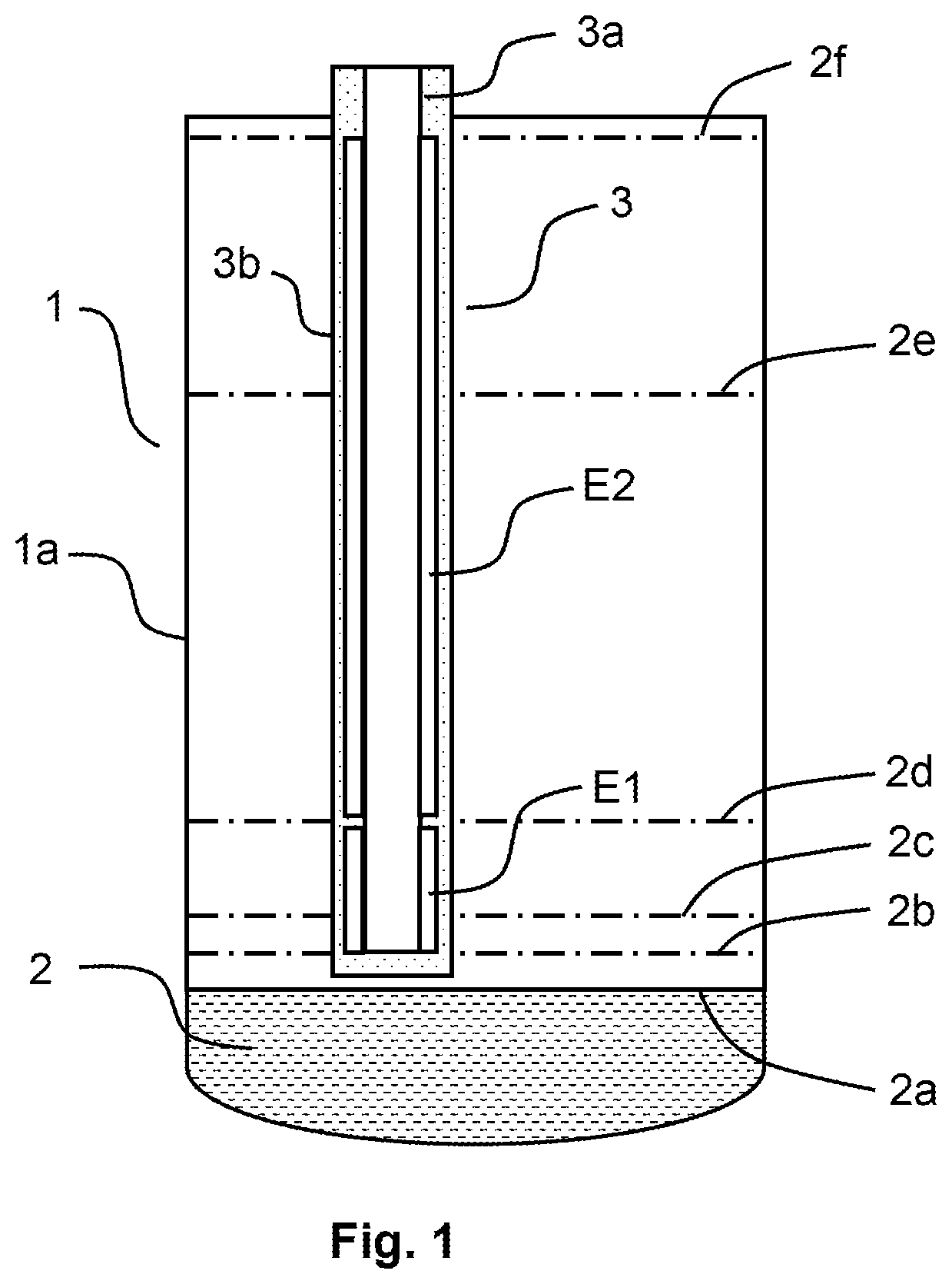
is a schematic sectional view of a filling level probe of a filling level measuring device according to the invention, introduced in a container, according to a first embodiment;
is a schematic sectional view of a filling level probe of a filling level measuring device according to the invention, introduced in a container, according to a second embodiment;
is a schematic diagram of a measurement arrangement of a filling level measuring device according to the invention with measuring electronics in the first measurement mode;
is a schematic diagram of a measurement arrangement of a filling level measuring device according to the invention with measuring electronics in the second measurement mode;
is a schematic diagram of a measurement arrangement of a filling level measuring device according to the invention with measuring electronics in the third measurement mode;
is a schematic flowchart of a method for capacitive filling level measurement according to the invention;
is a schematic diagram of the relative changes in capacitance as measured in the first, second, and third measurement modes as a function of the level of filling material in the container;
is a schematic diagram of a filling level calculated when the container is being filled as a function of the level of filling material in the container; and
is a schematic diagram of a filling level calculated when the container is being emptied as a function of the level of filling material in the container.
DETAILED DESCRIPTION
Preferred embodiments within the scope of the invention will now be described with reference to the drawings.
shows an exemplary schematic sectional view of a filling level probe 3 of a filling level measuring device according to the invention, placed in a container 1 for capacitive filling level measurement of filling material 2 in the form of liquids and/or bulk materials according to a first embodiment. is meant to illustrate an exemplary configuration and an exemplary installation position of the filling level probe 3 placed in container 1 , and to indicate exemplary filling levels 2 a , 2 b , 2 c , 2 d , 2 e , 2 f of a filling material 2 .
According to , the container 1 comprises a counter electrode, and in the illustrated example the wall 1 a of container 1 , i.e. container wall 1 a , is in the form of a counter electrode. However, in further embodiments, not shown, the counter electrode may also be attached to the container wall 1 a or arranged inside the container 1 .
In , the filling level probe 3 is mounted substantially vertically inside the container 1 . A first electrode E 1 and a second electrode E 2 are provided on filling level probe 3 . In , filling level probe 3 comprises a substrate 3 a , in particular made of and/or preferably surrounded by at least one electrically insulating material 3 b , on which the first and the second electrodes E 1 , E 2 are attached in alignment along their longitudinal extensions. In the illustrated example, this substrate 3 a is in the form of a rod, but may be in the form of a plate, for example, in an alternative embodiment.
In their installed state as shown in , the first electrode E 1 and the second electrode E 2 extend into the container 1 one after the other in alignment along their longitudinal extension and spaced apart from each other and substantially parallel and therefore also equidistant to the counter electrode, such that, when the container 1 is being filled, the first electrode E 1 will first be covered by filling material 2 before the second electrode E 2 is at least partially covered by filling material. Thus, in its installed state in the container 1 , the first electrode E 1 can be referred to as the lower electrode, and the second electrode E 2 can be referred to as the upper electrode. A measurement section is defined by the entire range between a first end of the first electrode E 1 remote from the second electrode E 2 and a second end of the second electrode E 2 remote from the first electrode E 1 . The first end of the first electrode E 1 remote from the second electrode E 2 corresponds to a lower end point of the measurement section, and the second end of the second electrode E 2 remote from the first electrode E 1 corresponds to an upper end point of the measurement section. Thus, the measurement section also includes the range where the first electrode E 1 and the second electrode E 2 are spaced apart from one another. This is ensured by choosing the extent of the spacing between the first and second electrodes E 1 , E 2 in the direction of the filling level to be as small as possible, so that, despite the electrical separation between the first and second electrodes E 1 , E 2 , the measurement section will exhibit nearly no interruption, at least almost no metrologically recognizable one, when the first and second electrodes E 1 , E 2 are connected together as measurement electrodes, resulting in a quasi-continuous measuring range for continuous determination of a filling level along the measurement section without any dead zones. In practical implementation, this is the case in particular when the resulting electric field of the first and second electrodes E 1 , E 2 to the counter electrode is the most continuous possible, i.e. the electric fields between the first electrode E 1 and the counter electrode and between the second electrode E 2 and the counter electrode overlap or at least adjoin each other. With regard to the choice of the spacing between the first and second electrodes E 1 , E 2 , the need for electrical separation between the first and second electrodes E 1 , E 2 implies a lower limit value, while the requirement for a measurement path that is as uninterrupted as possible implies an upper limit value. An acceptable spacing between the first and second electrodes E 1 , E 2 is therefore suitably derived substantially on the basis of the geometry of the filling level probe and is preferably less than half the width or the diameter of the first and/or second electrode E 1 , E 2 . In , the spacing between the first electrode E 1 and the second electrode E 2 is approximately 1 mm. However, embodiments in which the spacing is larger or even smaller are conceivable as well.
The first electrode E 1 has a first length L 1 and the second electrode has a second length L 2 , and in the example of the second length L 2 of the second electrode E 2 is approximately 5 times greater than the first length L 1 of the first electrode E 1 . In an alternative embodiment, the second length L 2 can in particular be of the same dimension as the first length L 1 or can be greater than the first length L 1 by a factor different from the factor mentioned above. If the second length L 2 is greater than the first length L 1 , so that the second length L 2 takes a larger proportion of the entire measurement section than the first length L 1 , this has the advantage, in particular when measuring the filling level while the container 1 is being filled, that relative changes in capacitance can be detected more accurately over a larger measuring range of the second electrode E 2 , and consequently a more accurate, less erroneous calculation of the respective filling level can be achieved. The measuring range of the second electrode E 2 describes the measuring range in a capacitor arrangement consisting of the counter electrode and the second electrode E 2 as the measurement electrode, while the measuring range of the first electrode E 1 describes the measuring range in a capacitor arrangement consisting of the counter electrode and the first electrode E 1 as the measurement electrode. If a filling level measurement is performed in the measuring range of the second electrode E 2 when the container 1 is being filled, there will also be available relative changes in capacitance as measured within the measuring range of the first electrode E 1 as measurement results for calculating the current filling level, in addition to the resulting relative changes in capacitance measured. Since the first and second lengths L 1 , L 2 of the first and second electrodes E 1 , E 2 extend in the height direction of the filling material, these lengths can be associated with corresponding filling material levels in the container 1 .
As an alternative to the embodiment shown in , the first and/or second electrodes can also be configured as individual rings or plates with an insulator.
Furthermore, shows various possible filling levels 2 a , 2 b , 2 c , 2 d , 2 e , 2 f of a filling material 2 in the container 1 . Filling level 2 a which is below the first electrode E 1 indicates a filling level which is clearly outside the measuring range of filling level probe 3 , the measuring range of filling level probe 3 being substantially defined by a capacitor arrangement between the counter electrode and the measurement section. Accordingly, the filling level 2 a usually cannot be captured by the filling level probe 3 shown in .
At a filling level 2 b , a capacitor arrangement consisting of a counter electrode and a first electrode E 1 as the measurement electrode will already be capable of measuring a relative change in capacitance compared to a completely empty container 1 . The magnitude of the relative change in capacitance is a function of the permittivity of the filling material 2 in each case.
Filling level 2 c corresponds to a filling level which is within the measuring range of the first electrode E 1 , so that a relative change in capacitance compared to a completely empty container 1 can be measured in the capacitor arrangement consisting of the counter electrode and the first electrode E 1 as the measurement electrode. If the first electrode E 1 is not operated as a measurement electrode, but only the second electrode E 2 , it will be impossible to measure any relative change in capacitance compared to a completely empty container 1 at a filling level 2 c.
Filling level 2 d corresponds to a filling level that is within a range in which the first electrode E 1 and the second electrode E 2 are electrically isolated and spaced apart from one another. Thus, the first electrode E 1 will be completely covered by filling material 2 at the filling level 2 d . The relative change in capacitance measured in the capacitor arrangement consisting of the counter electrode and the first electrode E 1 as the measurement electrode will assume a maximum value that depends on the permittivity of the filling material 2 , and will no longer change significantly as a result of continuing filling of the container 1 with the same filling material 2 , since such a change in the filling level is outside the measuring range of the first electrode E 1 . If the permittivity of the filling material 2 is sufficiently high, a relative change in capacitance may already be measurable in a capacitor arrangement consisting of the counter electrode and the second electrode E 2 as the measurement electrode.
Filling level 2 e corresponds to a filling level which is within the measuring range of the second electrode E 2 . In a capacitor arrangement consisting of the counter electrode and the second electrode E 2 as the measurement electrode, a relative change in capacitance compared to a completely empty container 1 will therefore be measurable, which increases while the container 1 is filled and decreases while the container 1 is emptied. If, on the other hand, only the first electrode E 1 is operated as a measurement electrode, the relative change in capacitance measured at filling level 2 e will substantially corresponds to the relative change in capacitance measured at filling level 2 d , since a change to filling level 2 e is outside the measuring range of the first electrode E 1 .
Filling level 2 f is a maximum filling level in the container 1 . In the present example of , the maximum filling level can be equated with a filling level up to the upper end of the second electrode E 2 or up to the upper end of the measurement section of filling level probe 3 , so that the first and second electrodes E 1 , E 2 are completely covered by filling material 2 . Irrespective of whether only the first electrode E 1 or only the second electrode E 2 is operated as a measurement electrode, or whether both the first and second electrodes E 1 , E 2 are operated as interconnected measurement electrodes, the relative change in capacitance measured at the filling level 2 f will always substantially be a maximum value.
shows an exemplary schematic sectional view of a filling level probe 3 placed in a container 1 of a filling level measuring device according to the invention for capacitive filling level measurement of filling material 2 in the form of liquids and/or bulk materials according to a second embodiment. The embodiment shown in differs from the embodiment shown in only by the fact that the filling level probe 3 is mounted substantially vertically inside the container wall 1 a and has a shielding electrode S. Shielding electrode S is disposed between the first end of the first electrode E 1 , i.e. the lower end of the first electrode E 1 , and a bottom of the container 1 . Shielding electrode S allows to shield the electric field of the first electrode E 1 towards the bottom of the container 1 . The feature of a shielding electrode S integrated in the filling level probe 3 should be considered independently of how the filling level probe 3 is mounted in the container 1 . In an alternative embodiment, the filling level probe can also be mounted substantially vertically on the container wall.
Each of the filling level probes shown in can be connected to measuring electronics included in the filling level measuring device according to the invention. , 4 , and 5 each show a schematic diagram of a measurement arrangement of a filling level measuring device according to the invention with measuring electronics 4 . In the present example, measuring electronics 4 is a three-electrode measuring electronics comprising a capacitive measurement circuit 5 which is configured to provide a measurement potential 5 a , a shielding potential 5 b , and a counter electrode potential 5 c . The measurement electronics 4 furthermore comprise a switching unit 6 which includes a first switch 6 a that can be electrically connected to the first electrode E 1 , and a second switch 6 b that can be electrically connected to the second electrode E 2 . First switch 6 a is adapted to switch over between measurement potential 5 a or shielding potential 5 b that can be applied to the first electrode E 1 , and second switch 6 b is adapted to switch over between measurement potential 5 a or shielding potential 5 b that can be applied to the second electrode E 2 . Counter electrode potential 5 c is always applied to the counter electrode, and in the container wall 1 a is in the form of a counter electrode, by way of example. With the aid of switching unit 6 , the filling level measuring device according to the invention can be operated in first, second, and third measurement modes, and in each of the three measurement modes, the measurement potential 5 a is applied to at least one of the first and second electrodes E 1 , E 2 .
, 4 , and 5 differ from one another in terms of the measurement mode set by the switching unit 6 . In , the measuring electronics 4 are set up to operate the filling level measuring device in the first measurement mode, in which the first switch 6 a and the second switch 6 b are set such that the measurement potential 5 a is applied to the first electrode E 1 and the shielding potential 5 b is applied to the second electrode E 2 . Thus, a capacitance can be measured in a capacitor arrangement consisting of the counter electrode and the first electrode E 1 as the measurement electrode, which is determined in the measuring electronics 4 as a relative change in capacitance C 1 compared to a completely empty container 1 .
In contrast to , the measuring electronics 4 in are set so as to operate the filling level measuring device in the second measurement mode. In the second measurement mode, first switch 6 a is set such that the shielding potential 5 b is applied to the first electrode E 1 , while second switch 6 b is set such that the measurement potential 5 a is applied to the second electrode E 2 . Thus, a capacitance can be measured in a capacitor arrangement consisting of the counter electrode and the second electrode E 2 as the measurement electrode, which again is determined in the measuring electronics 4 as a relative change in capacitance C 2 compared to a completely empty container 1 .
, on the other hand, shows measuring electronics 4 set up to operate the filling level measuring device in the third measurement mode. In the third measurement mode, the first and second switches 6 a , 6 b of switching unit 6 are set such that the measurement potential 5 a is applied to both the first electrode E 1 and the second electrode E 2 . The first and second electrodes E 1 , E 2 thus function together as a measurement electrode and, together with the counter electrode, define a capacitor arrangement which can be used to measure a capacitance, which is determined by the measuring electronics 4 as a relative change in capacitance C 3 compared to a completely empty container 1 . It should be noted that the capacitance measured when the first and second electrodes E 1 , E 2 are connected together as measurement electrodes does not correspond to the sum of the capacitances which are measured in a capacitor arrangement consisting of the counter electrode and the first electrode E 1 as a measurement electrode and of the counter electrode and the second electrode E 2 as the measurement electrode, due to non-linearities caused by parasitic capacitances in the signal path.
The measuring electronics 4 shown in , 4 , and 5 furthermore always include an evaluation unit 7 that is electrically connected to the switching unit 6 and measurement circuit 5 . Evaluation unit 7 is adapted to control the switching unit 6 and to calculate the current filling level on the basis of the relative changes in capacitance as measured in measurement electronics 4 compared to a completely empty container 1 in each of the three measurement modes.
shows a schematic flowchart of an exemplary method according to the invention for capacitive filling level measurement of filling material in a container that includes a counter electrode, and gives a basic overview of a possible processing sequence in which the container is first filled with filling material (solid line) and then can be emptied (dashed line). Thus, what is not shown in is that the method will only be carried out after a filling level probe comprising a first electrode E 1 and a second electrode E 2 for measuring the filling level has been introduced into the container. As can be seen in , for example, in the installed state of the filling level probe, the first and second electrodes E 1 , E 2 are arranged such that when the container is being filled, the first electrode E 1 will first be covered by filling material before the second electrode E 2 is at least partially covered by filling material, and with the first and second electrodes extending into the container in longitudinal alignment one after the other and spaced apart from each other and substantially parallel to the counter electrode. As already described with reference to , a measurement section is defined by the entire range between the first end of first electrode E 1 remote from the second electrode E 2 and the second end of second electrode E 2 remote from the first electrode. Once a measurement potential, a shielding potential, and a counter electrode potential have been provided, the first and second electrode and the counter electrode have been connected to the measurement electronics, as shown in , 4 , 5 by way of example, and the counter electrode potential has been applied to the counter electrode, the method for capacitive filling level measurement can be carried out using a calibrated filling level probe.
A method step not illustrated in for the sake of clarity is the operation of the first and second electrodes E 1 , E 2 in a first, second, or third measurement mode by switching over between a measurement potential or shielding potential to be applied to the first and second electrode E 1 , E 2 , respectively, of the filling level probe. In the first measurement mode, the measurement potential is applied to the first electrode E 1 and the shielding potential to the second electrode E 2 , as shown in , while in the second measurement mode the shielding potential is applied to the first electrode E 1 and the measurement potential to the second electrode E 2 , as shown in . In the third measurement mode, the measurement potential is applied to the first and second electrodes E 1 , E 2 , as shown in . This is followed by the step of performing at least one filling level measurement, by measuring relative changes in capacitance with respect to a completely empty container in each of the three measurement modes while the container is being filled and/or while the container is being emptied, and using them for calculating the filling level. A filling level measurement is preferably performed continuously, as is the case in the example of . More particularly, the first, second, and third measurement modes are each executed cyclically while the filling level measurement is being carried out, specifically independently of the respective current filling level. This enables a quick comparison of the relative changes in capacitance measured in each of the three measurement modes, so that the current filling level can be calculated more reliably and more precisely than would be the case without cyclical execution.
Preferably, two different algorithms A 1 , A 2 are executed while the filling level measurement is being carried out, and for calculating a current filling level on the basis of the relative changes in capacitance measured for this purpose, the respective algorithm A 1 , A 2 to be executed is selected. Explanations of the two algorithms A 1 , A 2 mentioned in follow below.
As illustrated in , before performing a filling level measurement, it may optionally first be checked whether a calibration measurement for calibrating the filling level probe has been performed. Thereafter, optionally, it may be checked whether an empty calibration was done as well. Empty calibration means a capacitance measurement with a completely empty container, i.e. with a container without any product in it.
Prior to starting a filling level measurement, it is always necessary for the filling level probe to be calibrated as mentioned above. This can be done, for example, by the method according to the invention for calibrating the filling level probe, as illustrated in as an alternative to the checking whether a calibration measurement and/or an empty calibration has been done. The method for calibrating the filling level probe is performed in a container that includes a counter electrode integrated therein. A filling level probe with a first electrode E 1 and a second electrode E 2 is introduced into the container for calibration, so that when the container is being filled, the first electrode E 1 will first be covered by filling material before the second electrode E 2 is at least partially covered by filling material, and the first and second electrodes E 1 , E 2 extend into the container in longitudinal alignment one after the other and spaced apart from each other and substantially parallel to the counter electrode, as illustrated in or 2 , for example. Thus, a measurement section is defined by the entire range between a first end of the first electrode E 1 remote from the second electrode E 2 and a second end of the second electrode E 2 remote from the first electrode E 1 . After the filling level probe has been introduced into the container, a measurement potential, a shielding potential, and a counter electrode potential are provided, and subsequently the first and second electrodes E 1 , E 2 and the counter electrode are connected to measuring electronics. The counter electrode potential is applied to the counter electrode. The first and second electrodes E 1 , E 2 are operated in the first, second, or third measurement mode which have already been defined in conjunction with the method for capacitive filling level measurement, by switching between a measurement potential or shielding potential that can be applied to the first and second electrodes E 1 , E 2 (see , 4 , 5 ). Finally, a calibration measurement is performed to calibrate the filling level probe, by determining relative changes in capacitance between a completely empty container and a maximum filling level in at least the first and third measurement modes. In this case, at least the first and the third measurement modes are preferably each executed cyclically. The relative changes in capacitance may also be determined in each of the three measurement modes in order to provide for a more precise calibration of the filling level probe using additional measurement data.
The calibration method is in particular carried out under the assumption that the underlying measurement arrangement substantially corresponds to a cylindrical capacitor. A first capacitance measurement is performed in empty calibration and a second capacitance measurement is performed at a predetermined maximum filling level of the container, i.e. in full calibration, by identifying relative changes in capacitance compared to the capacitances determined during empty calibration. A predetermined maximum filling level is in particular given when a filling material held in the container reaches a filling height up to the second end of the second electrode remote from the first electrode, and thus up to the upper end of the measurement section of the filling level probe, so that the first electrode and the second electrode are completely covered by this filling material.
The method for calibrating the filling level probe can also be performed without filling the container with filling material, for example using a calibration device mimicking a filling level measurement. The filling of the container with filling material may be simulated, for example, by having the counter electrode designed to be movable so that it can assume two different positions corresponding to a completely empty container and to a predetermined maximum filling level of the container. In this case, the predetermined maximum filling level corresponds to a simulated filling level up to the second end of the second electrode remote from the first electrode.
Furthermore, a calibration value can be calculated on the basis of the determined relative changes in capacitance as part of the method for calibrating the filling level probe. The calibration value is preferably substantially proportional to a ratio of the first length of the first electrode E 1 to the second length of the second electrode E 2 , which may also be a ratio between the first or second length and the total of the first and second lengths, and a ratio inverse thereto. The purpose of calibrating the filling level probe is therefore primarily to obtain information about the lengths ratio between the first electrode and the second electrode. In contrast to prior art documents, it is not necessary to determine a relative permittivity of the filling material as part of the calibration of the filling level probe.
As can be seen in , the optional steps for checking about a calibration measurement and an empty calibration are not necessary if the filling level probe was calibrated before performing a first level measurement according to the method described above, since an empty calibration is performed in at least the first and third measurement modes as part of the calibration measurement. However, in the case of a calibrated filling level probe that has not been calibrated as part of the calibration procedure described above, this check can be helpful in order to avoid measurement errors and, if necessary, to perform a respective empty calibration.
According to the processing sequence outlined in , a first threshold S 1 of the filling level is preferably detected based on relative changes in capacitance measured in the first measurement mode. This first threshold S 1 substantially corresponds to a level up to the first end of the first electrode E 1 remote from the second electrode E 2 , i.e. up to the lower end of the first electrode E 1 and thus the lower end of the measurement section of the filling level probe. The first threshold S 1 does not necessarily mean a specific value, but rather a limited range of values around the lower end of the measurement section, and is therefore also referred to as the first filling material threshold. The method according to the invention allows to determine filling levels at least when the first threshold S 1 is exceeded while the container is being filled, and at least until it falls below the first threshold S 1 while the container is emptied. According to , it is therefore intended to check whether the first threshold or the first filling material threshold S 1 has been exceeded. This can be determined on the basis of relative changes in capacitance compared to the empty calibration, as measured at least in the first but also in the third measurement mode, and these values do not only depend on the filling level but also on the permittivity of the filling material. For example, in the case of a filling material which has a permittivity that differs only slightly from the permittivity of air, ε r =1.00059, the detection of relative changes in capacitance will be less precise and therefore more prone to errors than in the case of a filling material which has a permittivity that is significantly different from the permittivity of air.
As can be seen from , a first algorithm A 1 is preferably executed to calculate the filling level when the filling level increases, usually when the container is being filled, specifically at least as soon as the first threshold S 1 is exceeded. The first algorithm A 1 evaluates a ratio of the relative change in capacitance measured in the first measurement mode and the relative change in capacitance measured in the second measurement mode, taking into account the lengths ratio between the first and second electrodes E 1 , E 2 as resulting from the calibration of the filling level probe. According to , the first algorithm A 1 is an adaptive algorithm, since it gradually adapts the calculation of the filling level and, if necessary, improves it. Depending on whether the container is being filled or emptied, (filling) and (emptying) illustrate, at which heights of filling material in the container the adaptive algorithm can in principle be executed for calculating the filling level. According to , the adaptive algorithm embodied as the first algorithm A 1 can even be executed below the first threshold S 1 . In this case, during filling, the adaptive algorithm will output a non-zero calculated filling level only shortly before the first threshold S 1 is reached, while during emptying it will continuously output a calculated filling level that gradually approaches zero.
Furthermore, the method for capacitive filling level measurement according to the exemplary flowchart of comprises the step of detecting a second threshold S 2 of the filling level and in particular the step of checking whether the second threshold S 2 has been exceeded, on the basis of relative changes in capacitance as measured in at least the first and second measurement modes. The second threshold S 2 substantially corresponds to a filling level corresponding to filling level 2 d in and is in a range in which the first and the second electrodes E 1 , E 2 are spaced apart, so that the first electrode E 1 is completely covered by filling material and the second electrode E 2 is not covered by filling material. Second threshold S 2 , also referred to as the second filling material threshold S 2 , does not necessarily have to be limited to a specific value, but may accordingly include a limited range of values, namely the range in which the first and second electrodes E 1 , E 2 are spaced apart from one another. However, since the spacing between the first and second electrodes E 1 , E 2 is as small as possible, preferably less than half the respective width of the electrode or the respective diameter of the electrode, the second threshold S 2 can be detected relatively precisely. When the container is being filled, the second threshold S 2 can for instance be detected by the fact that, once it is exceeded, the relative change in capacitance measured in the first measurement mode does no longer change significantly, since a filling level change within the measuring range of the second electrode E 2 is outside the measuring range covered by the first measurement mode of the first electrode E 1 , and on the other hand since the relative change in capacitance measured in the second measurement mode changes noticeably, i.e. increases as a function of the permittivity of the filling material (see ). While the container is emptied, the second threshold S 2 can be determined based on the fact that once it is undershot, the relative change in capacitance measured in the first measurement mode will change noticeably on the one hand, in particular it will decrease from a previously assumed maximum value as a function of the permittivity of the filling material, and on the other hand the relative change in capacitance measured in the second measurement mode will no longer change significantly, so that substantially no change in capacitance can be measured anymore compared to a capacitance value detected during empty calibration (see ), since a filling level that has fallen below the second threshold S 2 is outside the measuring range covered by the second measurement mode. Similarly, it can be checked whether the second threshold S 2 has been exceeded, or not undershot.
If the check establishes that the second threshold S 2 has not been exceeded, a new check is carried out according to to determine whether the first threshold S 1 has been exceeded by the respective current filling level. If the answer is yes, which should always be the case when the container is being filled, then the previously described adaptive algorithm for calculating the current filling level will be executed as outlined in by way of example.
If, however, the check establishes that the current filling level has exceeded the second threshold S 2 , the expected maximum filling level in the container is preferably calculated according to , which substantially corresponds to filling level 2 f as indicated in . In order to calculate the expected maximum filling level, a filling level between the second threshold S 2 and the maximum filling level is first calculated, in particular a maximum relative change in capacitance assuming a maximum filling level, i.e. a maximum relative change in capacitance which corresponds to the relative change in capacitance at the maximum filling level. The maximum relative change in capacitance is preferably calculated continuously, and the calculation is based on the respective relative changes in capacitance as measured in the first measurement mode and on a calibration value of the filling level probe, in particular a calibration value calculated as part of the method for calibrating the filling level probe. As already explained above and as can be seen in , the change in capacitance measured in the first measurement mode assumes a maximum value depending on the permittivity of the filling material once the second threshold has been exceeded, since a filling level in this range is outside the measuring range of the first electrode E 1 and the first electrode E 1 is then completely covered by filling material. On the basis of the maximum value detected in the first measurement mode, a maximum relative change in capacitance likely to be given at the maximum filling level can be calculated, in particular by multiplication with the lengths ratio of the first and second electrodes E 1 , E 2 as obtained from the calibration value. The permittivity of the filling material per se is not required for calculating the maximum relative change in capacitance, since it is already implicitly taken into account by the respective maximum value detected in the first measurement mode. Consequently, a separate determination of a relative permittivity of the filling material using an additional reference electrode can be dispensed with. The maximum relative change in capacitance to be expected is calculated linearly under the assumption that the counter electrode extends substantially parallel and equidistantly to the first and second electrodes E 1 , E 2 over the entire measurement section. If the current filling level falls below the second threshold S 2 , the previously calculated maximum relative change in capacity is recorded. If the second threshold S 2 is exceeded again, the continuous calculation of the maximum relative change in capacitance is continued.
Furthermore, the respective filling level can be calculated based on relative changes in capacitance measured in the third measurement mode at a filling level between the second threshold S 2 and the maximum filling level, which corresponds to a calculated maximum relative change in capacitance or a maximum relative change in capacitance determined as a result of performing the calibration measurement. In particular a ratio between the relative change in capacitance as measured in the third measurement mode and the maximum relative change in capacitance as calculated or detected as part of the calibration measurement is used to calculate the respective current filling level. If the measurement arrangement and the filling material are identical when performing the filling level measurement compared to the measurement arrangement and the filling material in the context of the calibration measurement, the relative change in capacitance as detected in the context of the calibration measurement at the maximum filling level in the third measurement mode can be used as the maximum relative change in capacitance. However, if the measurement arrangement used for the filling level measurement and/or the permittivity of the filling material differ from those of the calibration measurement, the maximum relative change in capacitance has to be calculated and used for the filling level calculation. Measurement arrangement refers to the container geometry, for example, to the installation position of the filling level probe in relation to the container and counter electrode, and/or to the installation position of the counter electrode in the container.
An example of such a filling level calculation is given in . According to the processing sequence outlined in , a linear algorithm is executed as the second algorithm A 2 for calculating the current filling level, specifically while the filling level is increasing, as indicated by the arrow shown in , when the second threshold S 2 has been exceeded (see ), and in the case of a decreasing filling level, as indicated by the arrow shown in , until the first threshold S 1 is undershot (see ). Thus, when the filling level increases, enabling 11 of the linear algorithm, i.e. the second algorithm A 2 , occurs as soon as the second threshold S 2 is exceeded, as indicated in , and when the filling level decreases, disabling 12 of the linear algorithm, i.e. the second algorithm A 2 , occurs as soon as the first threshold S 1 is undershot, as indicated in . The linear algorithm evaluates a ratio between the respective relative change in capacitance as measured at least in the third measurement mode and a maximum relative change in capacitance under the assumption of the maximum filling level. The maximum relative change in capacitance is either calculated or was previously determined as a result of performing the calibration measurement. Based on the evaluated ratio, the linear algorithm determines the current filling level independently of the permittivity of the filling material. The reason for the designation “linear algorithm” is that for the calculation of the current filling level, the linear algorithm assumes a linearity between the current filling level to be calculated and the relative change in capacitance as measured at least in the third measurement mode. Since the linear algorithm has more measurement data available than the adaptive algorithm, for example the maximum value of the capacitance change measured in the first measurement mode, the linear algorithm is able to calculate the current filling level more precisely than the adaptive algorithm.
If it is detected during the execution of the linear algorithm, in particular while the container is being emptied, that the current filling level has fallen below the second threshold S 2 , it will first be checked, according to , whether the current filling level has already fallen below the first threshold S 1 . If the answer is no, the linear algorithm according to continues to be executed. However, if the answer is yes, the execution of the linear algorithm is terminated or the linear algorithm is disabled, according to , reference numeral 12 . It is then possible, for example, to execute the adaptive algorithm for calculating a filling level until the container is completely empty, as indicated in . In addition, a new check is carried out at regular time intervals to determine whether the current filling level has exceeded the first threshold S 1 .
It may also be contemplated, as part of the method according to the invention for capacitive filling level measurement, to detect further thresholds in addition to the first and second thresholds S 1 , S 2 , which may be below or above the first and/or second thresholds S 1 , S 2 and preferably are based on continuously calculated relationships consisting of the relative changes in capacitance as measured in the first and second measurement modes. Such further threshold values allow to take into account any hystereses that may occur when detecting the relative changes in capacitance, whereby the accuracy of the filling level calculation can be improved.
shows a schematic diagram of the measured relative changes in capacitance in the first, second, and third measurement modes as a function of the height of the filling material, or the filling level, in the container. When the filling level probe is operated in the first measurement mode, relative changes in capacitance C 1 as measured between the counter electrode and the first electrode E 1 as the measurement electrode can already be detected shortly before the lower end of the first electrode E 1 is reached, depending on the permittivity of the filling material. Under the assumption that the permittivity of the filling material does not change significantly, the value of the relative changes in capacitance C 1 measured in the first measurement mode will increase substantially linearly while the height of the filling material in the container increases. This linear increase ends approximately at a filling level corresponding to filling level 2 d in , that is in the vicinity of the second threshold value, where the value of the relative changes in capacitance C 1 measured in the first measurement mode reaches a maximum. When the filling level in the container continues to rise, a plateau will be formed at this maximum, which extends all the way to the maximum filling level.
When the filling level probe is operated in the second measurement mode, relative changes in capacitance C 2 measured between the counter electrode and the second electrode E 2 as the measurement electrode can already be detected before the lower end of the second electrode E 2 is reached, depending on the permittivity of the filling material. As illustrated in , the relative changes in capacitance C 2 may already be measurable at a filling level that falls into the measuring range of the first electrode E 1 , depending on the permittivity of the filling material. The relative changes in capacitance C 2 measured in the second measurement mode increase substantially linearly as a function of the level of the filling material in the container and the permittivity of the filling material, until the filling level of the filling material reaches the maximum filling level.
When the filling level probe is operated in the third measurement mode, relative changes in capacitance C 3 measured between the counter electrode and the interconnected first and second electrodes E 1 , E 2 as the measurement electrodes can be detected shortly before the lower end of the first electrode E 1 is reached, depending on the permittivity of the filling material, as is the case in the first measurement mode. Since, in the third measurement mode, the measuring range extends along the entire measurement section of the filling level probe, the relative changes in capacitance C 3 will increase substantially linearly over the entire measurement section, as a function of the filling level in the container and the permittivity of the filling material, until the level of the filling material in the container reaches the maximum level.
It should be noted here that all features that will be apparent to a person skilled in the art from the present description and the figures, can be combined both individually and in any combination with others features or groups of features disclosed in the present invention, even if these features were only described in conjunction with certain other features, unless this has been explicitly excluded or technical circumstances make such combinations impossible or pointless. For the sake of brevity and readability of the description, a comprehensive explicit description of all possible combinations of features has been avoided. The scope of protection of the present invention as defined by the claims is not limited by the specific embodiments of the invention as illustrated in the description and the drawings, which are given merely by way of example. Modifications to the disclosed embodiments will be obvious to those skilled in the art from the drawings, the specification, and the appended claims. The word “comprising” as recited in the claims does not exclude other elements or steps. The indefinite article “a” or “an” does not exclude a plural. A combination of features that are claimed in different patent claims is not excluded.
LIST OF REFERENCE NUMERALS
•
• 1 Container • 1 a Container wall • 2 Filling material • 2 a Filling level below first threshold • 2 b Filling level corresponding to first threshold S 1 • 2 c Filling level between first and second thresholds • 2 d Filling level corresponding to second threshold S 2 • 2 e Filling level between second threshold and maximum filling level • 2 f Maximum filling level • 3 Filling level probe • 3 a Substrate • 3 b Electrically insulating material • 4 Measuring electronics • 5 Measurement circuit • 5 a Measurement potential • 5 b Shielding potential • 5 c Counter electrode potential • 6 Switching unit • 6 a First switch • 6 b Second switch • 7 Evaluation unit • 11 Enabling of A 2 • 12 Disabling of A 2 • E 1 First electrode • E 2 Second electrode • S Shielding electrode • C 1 Relative change in capacitance measured in first measurement mode • C 2 Relative change in capacitance measured in second measurement mode • C 3 Relative change in capacitance measured in third measurement mode • S 1 First threshold • S 2 Second threshold • A 1 First algorithm • A 2 Second algorithm
Figures (9)
Citations
This patent cites (21)
- US3119266
- US4624139
- US6178818
- US7161361
- US8931340
- US9429461
- US10288467
- US2011/0314907
- US2020/0141789
- US2021/0262846
- US2819731
- US19528384
- US19749884
- US19916979
- US10251842
- US2735851
- US3457095
- USJA20164395
- US0026619
- US2004057281
- US2020113283