Beverage Capsule Cup with Enhanced Material Distribution
Abstract
A beverage brewing cup with a floor having a puncture area is disclosed.
Claims (19)
1. A beverage brewing cup, comprising: a side wall and a floor at least partially defining a product storage region; the floor having a center area, an inner gusset area, a puncture area, and an outer gusset area; the center area disposed axially above the puncture area, the inner gusset area extending between and interconnecting the center area and the puncture area; the side wall disposed axially above the puncture area and the outer gusset area, the outer gusset area extending between and interconnecting the puncture area and the side wall; the inner gusset area including a plurality of inner gussets; the outer gusset area including a plurality of triangular outer gussets; the puncture area in the floor disposed between and interconnecting the inner gusset area and the outer gusset area; and wherein the outer gusset area has a top edge coupled to a lower edge of the side wall, a bottom edge coupled to an outer edge of the puncture area, a plurality of outer gusset first tips, and a plurality of outer gusset second tips, wherein the outer gusset first tips and outer gusset second tips are arranged in an alternating circumferential pattern, wherein the outer gusset second tips are disposed radially outwardly of the outer gusset first tips, and wherein each outer gusset first tip has a first vertex each with a same shape among the plurality of outer gusset first tips and each outer gusset second tip has a second vertex each with a same shape among the plurality of outer gusset second tips; wherein each outer gusset first tip of the plurality of outer gusset first tips and each outer gusset second tip of the plurality of outer gusset second tips is disposed: (i) entirely below the lower edge of the side wall and (ii) above the bottom edge of the outer gusset area and the outer edge of the puncture area; and wherein the floor is formed of a thermoformable material.
13. A beverage brewing cup, comprising: a side wall and a floor at least partially defining a product storage region; a brim disposed axially opposite the floor, the brim surrounding an opening into the product storage region; the floor having a center area, an inner gusset area, a puncture area, and an outer gusset area; the center area disposed axially above the puncture area and the inner gusset area extending between and interconnecting the center area and the puncture area; the side wall disposed axially above the puncture area and the outer gusset area, the outer gusset area extending between and interconnecting the puncture area and the side wall; the puncture area in the floor disposed between and interconnecting the inner gusset area and the outer gusset area; the puncture area having a thickness that is less than a thickness of the center area; wherein the inner gusset area has a plurality of inner gussets and a plurality of inner gusset first tips; wherein the outer gusset area has a plurality of outer gussets and a plurality of outer gusset first tips; and wherein the outer gusset first tips have a radius of curvature that is less than a radius of curvature of the inner gusset first tips; wherein the floor is formed of a thermoformable material, wherein the puncture area includes an inner edge connected to the inner gusset area and an outer edge connected to the outer gusset area, and wherein the side wall includes a lower edge coupled to an upper edge of the outer gusset area, wherein the lower edge is entirely above the outer gusset area, and wherein the outer edge of the puncture area is entirely below the outer gusset area and the inner gusset area.
17. A beverage brewing cup, comprising: a side wall and a floor at least partially defining a product storage region; the floor having a center area, an inner gusset area, a puncture area, and an outer gusset area; the center area disposed axially above the puncture area and the inner gusset area extending between and interconnecting the center area and the puncture area; the side wall disposed entirely axially above the puncture area and the outer gusset area, the outer gusset area extending between and interconnecting the puncture area and the side wall; the inner gusset area including a plurality of inner gussets; the outer gusset area including a plurality of outer gussets; the puncture area in the floor disposed between and interconnecting the inner gusset area and the outer gusset area; wherein the inner gusset area has a plurality of inner gussets that includes a plurality of inner gusset first tips and the outer gusset area has a plurality of outer gussets including a plurality of outer gusset first tips; wherein the outer gusset first tips have a radius of curvature that is less than a radius of curvature of the inner gusset first tips; and wherein the outer gussets have a triangular shape with rounded first tips and wherein each inner gusset first tip of the plurality of inner gusset first tips has a rounded shape with more pronounced rounded tips than the outer gusset first tips; wherein the floor is formed of a thermoformable material, and wherein the plurality of inner gussets have an inner gusset height and the plurality of outer gussets have an outer gusset height, and wherein the outer gusset height is greater than the inner gusset height such that the sidewall is entirely above the outer gusset area and the inner gusset area.
Show 16 dependent claims
2. The beverage brewing cup of claim 1 , wherein the puncture area is thinner than the center area.
3. The beverage brewing cup of claim 2 , wherein the puncture area has a thickness in the range of about 0.007″ to about 0.016″.
4. The beverage brewing cup of claim 2 , wherein the center area has a thickness in the range of about 0.015″ to about 0.030″.
5. The beverage brewing cup of claim 2 , wherein the center area has a thickness in the range of about 0.015″ to about 0.022″.
6. The beverage brewing cup of claim 1 , wherein the inner gusset area has a plurality of inner gusset first tips.
7. The beverage brewing cup of claim 6 , wherein the outer gusset first tips have a radius of curvature that is less than a radius of curvature of the inner gusset first tips.
8. The beverage brewing cup of claim 7 , wherein the outer gussets have rounded outer gusset first tips and wherein the inner gussets have a rounded shape with more pronounced rounded inner gusset first tips than the outer gusset first tips.
9. The beverage brewing cup of claim 1 , wherein the outer gusset first tips are disposed lower than the outer gusset second tips when the floor is lower than the side wall.
10. The beverage brewing cup of claim 8 , wherein the inner gussets have inner gusset second tips, and wherein the outer gusset first tips have a radius of curvature that is less than a radius of curvature of the inner gusset second tips.
11. The beverage brewing cup of claim 10 , wherein the inner gusset first tips and inner gusset second tips are arranged in an alternating circumferential pattern, and wherein the inner gusset second tips are disposed radially inwardly of the inner gusset first tips.
12. The beverage brewing cup of claim 11 , wherein the inner gusset first tips are disposed lower than the inner gusset second tips when the floor is lower than the side wall.
14. The beverage brewing cup of claim 13 , wherein the outer gussets have a triangular shape with rounded tips and wherein each inner gusset first tip of the inner gusset first tips has a rounded shape with more pronounced rounded tips than the outer gusset tips.
15. The beverage brewing cup of claim 13 , wherein the inner gussets have inner gusset second tips, and wherein the outer gusset first tips have a radius of curvature that is less than a radius of curvature of the inner gusset second tips.
16. The beverage brewing cup of claim 15 , wherein the inner gusset first tips and inner gusset second tips are arranged in an alternating circumferential pattern, and wherein the inner gusset second tips are disposed radially inwardly of the inner gusset first tips.
18. The beverage brewing cup of claim 17 , wherein the floor further comprises an outer edge interposed between the puncture area and the outer gusset area, wherein the outer edge is stepped downwardly relative to the puncture area, and wherein the outer gusset area is disposed entirely below the side wall.
19. The beverage brewing cup of claim 17 , wherein the plurality of inner gussets have a plurality of inner front edges extending downwardly at a first angle α relative to the center area and the plurality of outer gussets have a plurality of outer front edges extending downwardly at a second angle β relative to the center area, wherein first angle α is greater than second angle β.
Full Description
Show full text →
PRIORITY CLAIM
This application claims priority under 35 U.S.C. § 119(e) to U.S. Provisional Application Ser. No. 63/104,127 filed Oct. 22, 2020, which is expressly incorporated by reference herein.
TECHNICAL FIELD
The present disclosure relates generally to beverage capsule cup, and more specifically to a beverage capsule cup with enhanced material distribution, for example, in the bottom wall or floor of the cup, which may allow for a cup floor that is more easily punctured by a beverage brewing apparatus.
BACKGROUND
It is often desirable to make a beverage capsule for holding beverage brewing contents, such as coffee grounds and/or beverage flavoring, and the capsule may include a cup that may hold the contents and/or be punctured. For example, the cup may include a bottom wall or floor that may be punctured by a needle of a beverage brewing apparatus so that the contents may be used to brew or provide a beverage.
SUMMARY
Certain embodiments according to the present disclosure provide a beverage capsule cup with enhanced material distribution.
In one aspect, for instance, some embodiments may provide a beverage brewing cup, having a side wall and a floor at least partially defining a product storage region. The floor has a center area, an inner gusset area, a puncture area, and an outer gusset area. The center area is disposed axially above the puncture area, and the inner gusset area extends between the center area and the puncture area. The side wall is disposed axially above the puncture area and the outer gusset area extends between the puncture area and the side wall. The inner gusset area includes a plurality of inner gussets. The outer gusset area includes a plurality of outer gussets. The puncture area in the floor is disposed between the inner gusset area and the outer gusset area.
In another aspect, for instance, some embodiments may provide a beverage brewing cup having a side wall and a floor at least partially defining a product storage region. A brim is disposed axially opposite the floor, the brim surrounding an opening into the product storage region. The floor has a center area, an inner gusset area, a puncture area, and an outer gusset area. The center area is disposed axially above the puncture area and the inner gusset area extending between the center area and the puncture area. The side wall is disposed axially above the puncture area and the outer gusset area extending between the puncture area and the side wall. The puncture area in the floor disposed between the inner gusset area and the outer gusset area. The puncture area having a thickness that is less than a thickness of the center area.
In yet another aspect, for instance, some embodiments may provide a beverage brewing cup having a side wall and a floor at least partially defining a product storage region. The floor has a center area, an inner gusset area, a puncture area, and an outer gusset area. The center area is disposed axially above the puncture area and the inner gusset area extending between the center area and the puncture area. The side wall is disposed axially above the puncture area and the outer gusset area extend between the puncture area and the side wall. The inner gusset area includes a plurality of inner gussets. The outer gusset area includes a plurality of outer gussets. The puncture area in the floor is disposed between the inner gusset area and the outer gusset area. The beverage brewing cup is thermoformed such that the puncture area is thinner than the center area.
BRIEF DESCRIPTION OF THE DRAWINGS
The detailed description particularly refers to the accompanying figures, in which:
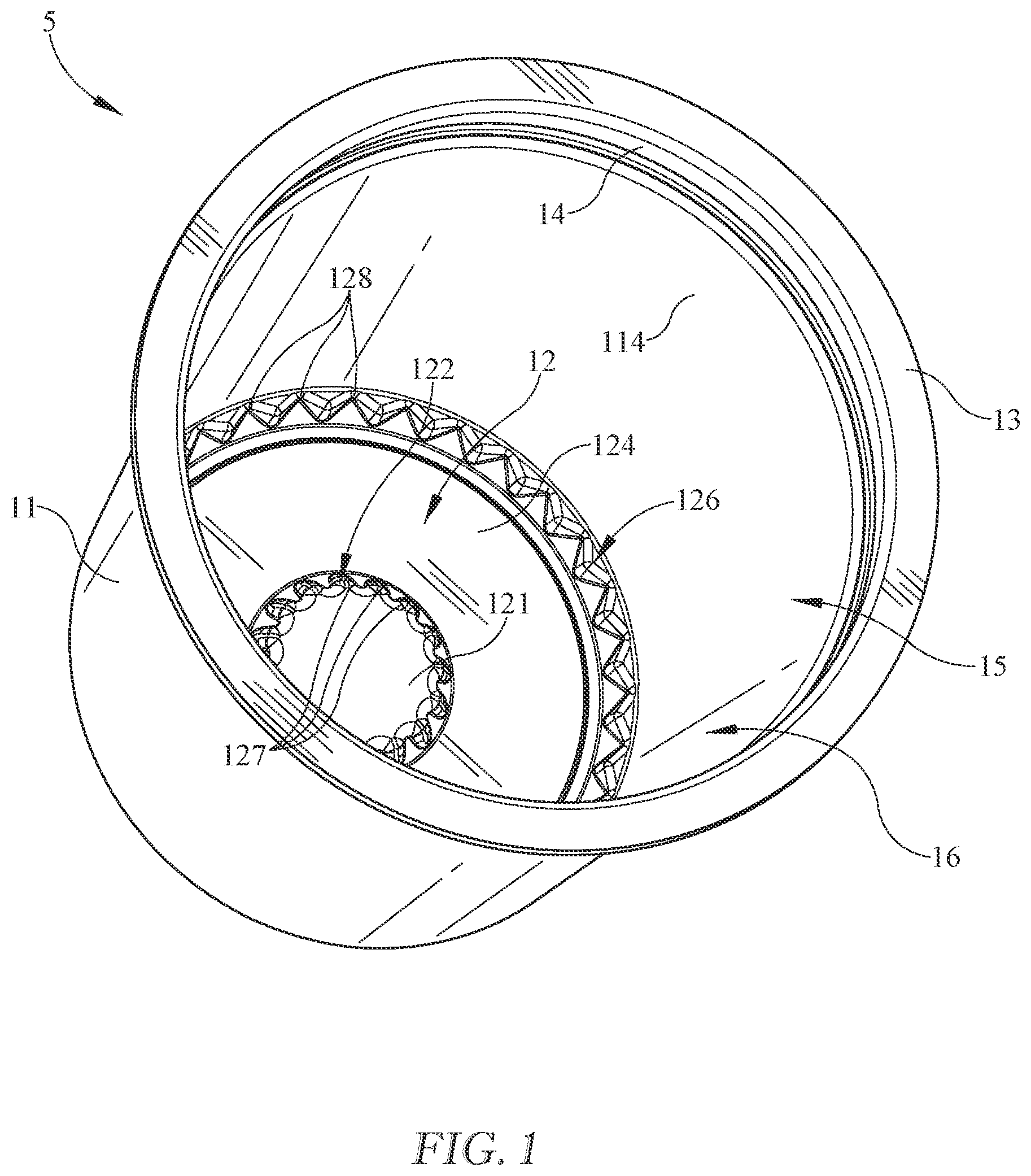
illustrates a perspective view of an exemplary embodiment of beverage capsule cup;
illustrates another perspective view of the beverage capsule cup of ;
illustrates a bottom perspective view of a portion of the beverage capsule cup of showing the floor in more detail;
illustrates a cross-section side view of the beverage capsule cup of ;
illustrates a cross-section perspective view of a portion of the beverage capsule cup of showing the floor in more detail;
illustrates a bottom view of the beverage capsule cup of ;
a illustrates a portion of a bottom of the beverage capsule of to show inner gussets in more detail; and
b illustrates another portion of the bottom of the beverage capsule of to show outer gussets in more detail.
DETAILED DESCRIPTION
Embodiments now will be described more fully hereinafter with reference to the accompanying drawings, in which some, but not all embodiments are shown. As used in the specification, and in the appended claims, the singular forms “a”, “an”, “the”, include plural referents unless the context clearly dictates otherwise.
The terms “substantial” or “substantially” may encompass the whole as specified, according to certain embodiments, or largely but not the whole specified according to other embodiments.
Some embodiments of a beverage capsule cup or container 5 and components thereof are shown, for example, in . Cup 5 may include a product storage region 16 at least partially defined by a side wall 11 and/or a bottom or floor 12 . Cup 5 may include a flange or brim 13 adjacent an opening 15 into product storage region 16 and/or adjacent an upper area 114 of side wall 11 . Cup 5 may include features such as brim 13 and/or a shoulder 14 for any of a variety of reasons, including, but not limited to, to provide structural support and/or strengthen cup 5 , to provide a lidding surface to contain and/or seal contents in product storage region 16 , and/or to facilitate stacking of one or more cups 5 , for example. Other features such as structural features or surface features like flutes, ribs, bumps, recesses, etc. may be included, for example in side wall 11 . It is understood that such features, if included, may be included in virtually any number or variety, they may be arranged in virtually any manner, for example symmetrical or asymmetrical, any or all of them may extend for virtually any amount of the height, width, and/or thickness of cup 5 or side wall 11 anywhere from floor 12 to brim 13 or anywhere in between.
Cup 5 may include a lid (not shown) for any of a variety of reasons, including but not limited to providing a sealed package for storing contents and/or for extending the life or shelf life of the contents. For example, container 5 may include contents for preparing a beverage, such as coffee grounds, tea leaves, or the like. In this example or in other embodiments, a lid may be puncturable or piercable for use in a beverage brewing apparatus, for instance. To help provide an extended shelf life, or for any other reason, cup 5 or any portion thereof may include a barrier or barrier properties, for example, to prevent, inhibit, and/or slow the transmission of oxygen or other gases that may through and/or into cup 5 .
Side wall 11 may have an upper area 114 and/or a lower area 113 . Upper area 114 may be proximate shoulder 14 and lower area 113 may be proximate floor 12 . Side wall 11 and/or upper area 114 or lower area 113 may have a side wall thickness measured from an outside surface to an inside surface of side wall 11 . Side wall 11 , together with bottom 12 , may at least partially define product storage region 16 .
Floor 12 may have a center area 121 and/or a puncture area 124 , as shown for example, in . Puncture area 124 may be configured to be pierced or punctured, for example, by an outlet needle or the like of a beverage brewing apparatus. Puncture area 124 may have an inner edge 123 and/or an outer edge 125 , either or both of which may at least partially define a boundary of puncture area 124 . Puncture area 124 may be stepped up or down relative to center area 121 and/or side wall 11 and/or lower area 113 of side wall 11 . For example, when set upright with floor 12 downward and brim 13 upward, puncture area 124 may be stepped down relative to center area 121 by an inner gusset area 122 , and/or puncture area 124 may be stepped down relative to lower area 113 of side wall 11 by an outer gusset area 126 . Inner edge 123 and/or outer edge 125 may be curved and/or stepped relative to puncture area 124 , for example with a relatively slight step down relative to puncture area 124 as shown in . A step or curve or the like at inner edge 123 and/or outer edge 125 may provide additional structural rigidity to floor 12 .
Inner gusset area 122 and/or outer gusset area 126 may include structural elements such as inner gussets 127 and/or outer gussets 128 , for example, to provide additional structural rigidity. Any or all gussets 128 in outer gusset area 126 may be substantially triangular in shape as shown in , or any other shape. Any or all gussets 127 in inner gusset area 122 may be triangular in shape and/or have somewhat blended, curved, or smoothed edges or corners as shown for example in . It is understood the shapes shown are examples and any of a variety of shapes, sizes, and/or configurations of gussets 127 , 128 or other structures may be used instead of or in addition to the gussets 127 , 128 shown in the figures. For example, as shown in , cup 5 may include about 32 outer gussets 128 and/or about 16 inner gussets 127 . It is understood that more or less than the number of inner gussets 127 and outer gussets 128 may be used, and the figures show one example. For example, inner gusset area 122 may include between about 8 and about 32 inner gussets 127 and/or outer gusset area 126 may include between about 12 and about 100 outer gussets 128 .
Moreover, while the figures show each outer gusset 128 as substantially similar in shape, and each inner gusset 127 as substantially similar in shape, it is understood that the sizes, shapes, and/or configurations of inner gussets 127 and/or outer gussets 128 may vary from gusset to gusset. It is also understood that, while inner gusset area 122 is shown as including inner gussets 127 throughout its perimeter, and while outer gusset area 126 is shown as including outer gussets 128 throughout its perimeter, there could be areas of inner gusset area 122 and/or outer gusset area 126 that do not include gussets 127 , 128 . For example, in alternative embodiments, the perimeter of inner gusset area 122 may intermittently include inner gussets 127 , with other portions of the perimeter substantially free of inner gussets 127 . In in alternative embodiments, the perimeter of outer gusset area 126 may intermittently include outer gussets 128 , with other portions of the perimeter substantially free of outer gussets 128 .
In some embodiments, such as that shown in , any or all of inner gussets 127 may include a first tip 127 a , a second tip 127 b , a first side 127 c , and/or a second side 127 d . First tip 127 a and/or second tip 127 b may be rounded, blended, and/or curved for any of a variety of reasons, including but not limited to reducing stress concentrations and allowing easier part removal when cup 5 and/or floor 12 is formed. For example, if cup 5 is thermoformed, having rounded tips 127 a and/or 127 b with relatively large radii of curvature may facilitate part removal from the thermoformer. First tip 128 a and/or second tip 128 b of any or all outer gussets 128 may be rounded in similar fashion or otherwise and, as shown in ., may have a smaller radii of curvature relative to inner tips 127 a and/or 127 b . Relatively larger radii of curvature of inner gusset tips 127 a and/or 127 b may give inner gussets 127 a shape that is triangular with rounded tips that are more pronounced than the rounded tips 128 a and/or 128 b of outer gussets 128 . Relatively smaller radii of curvature may provide additional structural rigidity as compared to larger radii of curvature. Inner gussets 127 and outer gussets 128 are shown in more detail, for example, in a and 7 b.
First tips 127 a of inner gusset 127 may be radially outward and/or lower than second tips 127 b of inner gusset 127 . First tips 128 a of outer gusset 128 may be radially inward and/or lower than second tip 128 b of outer gusset 128 . As used here to discuss tips 127 a , 127 b , 128 a , 128 b , lower may mean nearer floor 12 or puncture area 124 in a direction measured from top (e.g., brim 13 ) to bottom (e.g., floor 12 ).
First side 127 c and/or second side 127 d of inner gusset 127 may extend from first tip 127 a to an adjacent second tip 127 b , or vice versa. First side 127 c and/or second side 127 d may extend in a radial direction and/or an axial direction transverse to the radial direction. First side 128 c and/or second side 128 d of outer gusset 128 may extend from first tip 128 a to an adjacent second tip 127 b , or vice versa. First side 128 c and/or second side 128 d may extend in a radial direction and/or an axial direction transverse to the radial direction. As used herein, directional terms such as “inner” or “outer” may be used to describe relative locations of features in the radial direction. Directional terms such as “higher”, “lower”, “upper”, “above”, “below”, and the like may be used to describe relative locations of features in the axial or longitudinal direction.
As shown in , center area 121 may be raised relative to puncture area 124 . Center area 121 may have a thickness T 121 that is greater than a thickness T 124 of puncture area 124 . For example, cup 5 may be thermoformed from a sheet of material having a substantially constant thickness, but through the thermoforming process the puncture area may be stretch and thinned more than center area to provide a lesser thickness T 124 than thickness T 121 . Center area 121 may be raised relative to puncture area 124 , which may correspond to the height H 127 of inner gusset area 122 or inner gussets 127 , and/or inner gusset area 122 may be raised at an angle α relative to the horizontal, center area 121 , and/or puncture area 124 . For example, in some embodiments, height H 127 of inner gusset 127 may be about 0.073″. It is understood that height H 127 could vary. For example, in some embodiments, H 127 may be between about 0.010″ and about 0.300″. Inner gusset 127 may have a front edge 127 e extending at angle α relative to a substantially horizontal center area 121 . In illustrative embodiments, front edge 127 e may have a length of about 0.100″ and angle α may be about 124 degrees. Front edge 127 e may have a length in the range of about 0.010″ to about 0.500″ and/or angle α may be in the range of about 90 degrees to about 180 degrees, in the range of about 100 degrees to about 160 degrees, in the range of about 110 degrees to about 140 degrees, and/or in the range of about 120 degrees to about 130 degrees.
Outer gusset area 126 may include a step from floor 12 and/or outer edge 125 to a top of outer gusset 128 having a height Him. Outer gusset 128 may have a front edge 128 e extending at an angle β relative to the horizontal. For example, in some embodiments, height H 128 of outer gusset 128 may be about 0.082″. It is understood that height H 128 could vary. For example, in some embodiments, H 128 may be between about 0.010″ and about 0.300″. In illustrative embodiments, front edge 128 e may have a length of about 0.085″ and angle β may be about 100 degrees. Front edge 128 e may have a length in the range of about 0.010″ to about 0.500″ and/or angle β may be in the range of about 90 degrees to about 180 degrees, in the range of about 95 degrees to about 160 degrees, in the range of about 95 degrees to about 120 degrees, and/or in the range of about 95 degrees to about 110 degrees.
Cup 5 or any portion thereof may have a thickness or variety of thicknesses. For example, material thickness and/or material distribution may be optimized for easy puncturability of floor 12 and/or puncture area 124 by a beverage brewing machine needle, for structural rigidity, and/or to provide a light weight cup 5 that includes less material than other pods or cups. In some embodiments, for example, cup 5 may be thermoformed of a thermoplastic material such as polypropylene or to include polypropylene. One or more parts of the mold may include a vented plug to allow optimized, enhanced, and/or thinned material distribution, for example, in floor 12 and/or puncture area 124 .
Some exemplary cups 5 may be formed to include polyolefins such as polypropylene and/or to have material thickness of about or within the range of:
•
• at brim 13 of about 0.025″ to about 0.045″ • at upper area 114 of about 0.009″ to about 0.013″ • at lower area 113 of about 0.009″ to about 0.020″ • at outer gusset area 126 of about 0.011″ to about 0.018″ • at puncture area 124 of about 0.007″ to about 0.016″ (T 124 ) • at center area 0.015″ to about 0.030″ and/or of about 0.015″ to about 0.022″ (T 121 ) These or other embodiments of cup 5 may be formed, for example if thermoformed, from a sheet, disc, or piece of material that has a thickness in the range of about 0.020″ to about 0.200″, in the range of about 0.040″ to about 0.100″, in the range of about 0.050″ to about 0.060″, and/or about 0.058″.
As shown in , inner gusset area 122 and outer gusset area 126 may be substantially concentric circles of varying diameter, each including a series of inner gussets 127 and outer gussets 128 , respectively. A portion of inner gusset area 122 is shown in more detail in a and a portion of outer gusset area 126 is shown in more detail in b . Any or all inner gussets 127 may have a depth D 127 measured in a radial direction from first tip 127 a to second tip 127 b . Any or all outer gussets 128 may have a depth D 128 measured in a radial direction from first tip 128 a to second tip 128 b . In some embodiments, outer gussets 128 may have a depth D 128 that is deeper or greater than a depth D 127 of inner gussets 127 .
Inner gusset 127 may have a radius of curvature R 127a at first tip 127 a and/or a radius of curvature R 127b at second tip 127 b , as shown for example in a and 7 b . Outer gusset 128 may have a radius of curvature R 128a at first tip 128 a and/or a radius of curvature R 128b at second tip 128 b . In some embodiments, radii of curvature R 127a and/or R 127b of inner gussets 127 may be greater than radii of curvature R 128a and/or R 128b of outer gussets 128 . As discussed above, a smaller radius of curvature at either tip of outer gusset 128 may enhance structural rigidity and a larger radius of curvature at either tip of inner gusset 127 may facilitate part removal following thermoforming or molding.
It is understood that cup 5 and/or any component thereof may be made of any of a variety of materials, including, but not limited to, any of a variety of suitable plastics material, any other material, or any combination thereof. Suitable plastics material may include, but is not limited to, polyethylene terephthalate (PET), polyethylene (PE), polypropylene (PP), polystyrene (PS), high-density polyethylene (HDPE), low-density polyethylene (LDPE), linear low-density polyethylene (LLDPE), crystallized polyethylene terephthalate (CPET), mixtures and combinations thereof, or any other plastics material or any mixtures and combinations thereof. It is understood that multiple layers of material may be used for any of a variety of reasons, including to improve barrier properties, or to provide known functions related to multiple layer structures. The multiple layers, if included, may be of various materials, including but not limited to those recited herein.
It is further understood that cup 5 or any component thereof may be substantially rigid, substantially flexible, a hybrid of rigid and flexible, or any combination of rigid, flexible, and/or hybrid, such as having some areas be flexible and some rigid. It is understood that these examples are merely illustrative, are not limiting, and are provided to illustrate the versatility of options available in various embodiments of cup 5 .
It is further understood that any of a variety of processes or combination thereof may be used to form cup 5 , any component thereof, or any layer or substrate used therein. For example, any component, layer, or substrate, or combination thereof, may be thermoformed, injection molded, injection stretch blow molded, blow molded, extrusion blow molded, coextruded, subjected to any other suitable process, or subjected to any combination thereof. In some embodiments, cup 5 and/or any component thereof may be formed substantially of thermoformed polypropylene. Various materials and/or processes may be used to form cup 5 and/or any component thereof as will be understood by one of ordinary skill in the art. In some embodiments, cup 5 may be substantially a one-piece design and/or substantially formed as an integral or unitary structure.
These and other modifications and variations may be practiced by those of ordinary skill in the art without departing from the spirit and scope, which is more particularly set forth in the appended claims. In addition, it should be understood that aspects of the various embodiments may be interchanged in whole or in part. Furthermore, those of ordinary skill in the art will appreciate that the foregoing description is by way of example only, and it is not intended to limit the scope of that which is described in the claims. Therefore, the spirit and scope of the appended claims should not be limited to the exemplary description of the versions contained herein.
Figures (4)
Citations
This patent cites (179)
- US3077284
- US3530917
- US3721367
- US3795182
- US4847148
- US4935089
- US5012928
- US5325765
- US5840189
- US5849401
- US5856406
- US5927179
- USD438794
- USD452433
- USD452434
- US6440256
- USD468202
- USD474110
- USD474111
- US6589577
- US6607762
- US6645537
- US6655260
- US6810788
- USD502362
- US6884450
- USD511965
- USD513152
- USD515970
- USD519831
- US7105106
- USD546672
- USD551909
- US7328651
- USD568156
- USD570650
- USD574703
- USD577288
- USD577994
- US7464638
- US7476710
- US7531198
- US7585917
- USD606363
- USD607315
- USD607329
- US7662885
- US7685931
- USD637484
- USD638290
- USD647398
- USD647399
- USD649037
- USD649054
- US8053051
- US8067501
- USD652292
- US8173747
- USD663999
- US8252351
- USD668538
- US8291812
- US8361527
- USD675519
- US8409676
- USD681448
- USD686916
- US8474368
- USD687297
- US8522669
- USD697797
- US8621981
- USD698649
- USD700839
- US8685479
- US8720320
- USD708057
- USD710686
- US8794125
- US8808778
- US8828895
- USD715649
- USD716648
- USD730174
- US9085410
- USD736615
- USD747187
- US9260596
- US9326635
- US9415913
- US9732167
- US11000148
- US2002/0020659
- US2003/0222089
- US2004/0045443
- US2005/0051478
- US2005/0287251
- US2007/0098933
- US2007/0144356
- US2010/0064899
- US2010/0288131
- US2010/0303964
- US2011/0041702
- US2011/0064852
- US2011/0151075
- US2011/0274802
- US2012/0097602
- US2012/0118166
- US2012/0207895
- US2012/0207896
- US2012/0241352
- US2012/0276264
- US2012/0308688
- US2013/0059039
- US2013/0061764
- US2013/0064936
- US2013/0068108
- US2013/0101716
- US2013/0122167
- US2013/0129872
- US2013/0323129
- US2013/0323370
- US2013/0340626
- US2013/0344205
- US2014/0106036
- US2014/0120217
- US2014/0120218
- US2014/0120288
- US2014/0141128
- US2014/0161937
- US2014/0178538
- US2014/0196608
- US2014/0212546
- US2014/0220191
- US2014/0272018
- US2014/0290493
- US2014/0308405
- US2014/0308406
- US2014/0311098
- US2014/0318380
- US2014/0363655
- US2015/0191607
- US2015/0298897
- US2015/0314954
- US2015/0336736
- US2016/0016389
- US2016/0039601
- US2016/0227957
- US2016/0332805
- US2016/0355306
- US2017/0036854
- US2017/0042362
- US2017/0055761
- US2017/0121050
- US2017/0266933
- US2017/0367521
- US2018/0001604
- US2018/0042258
- US2018/0079564
- US2018/0118450
- US2018/0228314
- US2018/0334319
- US2019/0084759
- US2019/0119036
- US2019/0329969
- US2021/0070537
- US2021/0228017
- US2586792
- US2618863
- US2840141
- US2650797
- US2932176
- US1073281
- US2012076135
- US2013132436
- US2014128315
- US2015191565
- US2016174671
- US2019238898