Integrated Circuit and Signal Transmission Method
Abstract
An integrated circuit is disclosed. The integrated circuit is coupled to a circuit board. The circuit board includes several signal pair channels. The integrated circuit includes several output terminals and a control circuit. The control circuit is configured to configure several output signals output to several signal pair channels by several output terminals, so that a first signal pair channel and a second signal pair channel of several signal pair channels receive and output several output signals, so that a third signal pair channel of several signal pair channels shields an interference between the first signal pair channel and the second signal pair channel. The third signal pair channel is adjacent to the first signal pair channel and the second signal pair channel, and the third signal pair channel is located between the first signal pair channel and the second signal pair channel.
Claims (20)
1. An integrated circuit, coupled to a circuit board, the circuit board comprises a plurality of signal pair channels, wherein the integrated circuit comprises: a plurality of output terminals; and a control circuit, coupled to the plurality of output terminals, configured to configure a plurality of output signals output to the plurality of signal pair channels by the plurality of output terminals, so that a first signal pair channel and a second signal pair channel of the plurality of signal pair channels receive and output the plurality of output signals, so that a third signal pair channel of the plurality of signal pair channels shields an interference between the first signal pair channel and the second signal pair channel, wherein the third signal pair channel is adjacent to the first signal pair channel and the second signal pair channel, and the third signal pair channel is located between the first signal pair channel and the second signal pair channel.
11. A signal transmission method, suitable for an integrated circuit, wherein the integrated circuit is coupled to a circuit board, the circuit board comprises a plurality of signal pair channels, wherein the signal transmission method comprises: configuring a plurality of output signals output to the plurality of signal pair channels of the integrated circuit by a plurality of output terminals by a control circuit of the integrated circuit; and outputting the plurality of output signals by a plurality of output terminals of the integrated circuit, so that a first signal pair channel and a second signal pair channel of the plurality of signal pair channels receive and output the plurality of output signals, so that a third signal pair channel of the plurality of signal pair channels shields an interference between the first signal pair channel and the second signal pair channel; wherein the third signal pair channel is adjacent to the first signal pair channel and the second signal pair channel, and the third signal pair channel is located between the first signal pair channel and the second signal pair channel.
Show 18 dependent claims
2. The integrated circuit of claim 1 , wherein the control circuit is further configured to configure a first part of the plurality of output terminals to output the plurality of output signals to a first part of the plurality of signal pair channels, and to configure a second part of the plurality of output terminals to output a plurality of shield signals to a second part of the plurality of signal pair channels, so that the second part of the plurality of signal pair channels shields an interference between the first part of the plurality of signal pair channels.
3. The integrated circuit of claim 2 , wherein the plurality of shield signals comprise a plurality of high impedance obstructive state signals.
4. The integrated circuit of claim 2 , wherein the plurality of shield signals comprises a plurality of direct current voltages.
5. The integrated circuit of claim 2 , wherein the second part of the plurality of signal pair channels intersects between the first part of the plurality of signal pair channels.
6. The integrated circuit of claim 2 , wherein the control circuit is further configured to select the first part of the plurality of output terminals according to a plurality of wire lengths of the plurality of signal pair channels to output the plurality of output signals to the first part of the plurality of signal pair channels.
7. The integrated circuit of claim 2 , wherein the control circuit further comprises: a multiplexer, configured to output the plurality of output signals to the first part of the plurality of signal pair channels.
8. The integrated circuit of claim 1 , further comprising: a ground wire, wherein the ground wire is extended from the integrated circuit to the circuit board, and is located between a fourth signal pair channel and a fifth signal pair channel of the plurality of signal pair channels, and the ground wire is adjacent to the fourth signal pair channel and the fifth signal pair channel, so as to shield an interference between the fourth signal pair channel and the fifth signal pair channel; wherein the fourth signal pair channel and the fifth signal pair channel receive and output the plurality of output signals.
9. The integrated circuit of claim 1 , wherein the plurality of output terminals transmit the plurality of output signals to the plurality of signal pair channels through a connector.
10. The integrated circuit of claim 1 , wherein the third signal pair channel is pulled to ground through a pad.
12. The signal transmission method of claim 11 , further comprising: configuring a first part of the plurality of output terminals to output the plurality of output signals to a first part of the plurality of signal pair channels; and configuring a second part of the plurality of output terminals to output a plurality of shield signals to a second part of the plurality of signal pair channels, so that the second part of the plurality of signal pair channels shields an interference between the first part of the plurality of signal pair channels.
13. The signal transmission method of claim 12 , wherein the plurality of shield signals comprise a plurality of high impedance obstructive state signals.
14. The signal transmission method of claim 12 , wherein the plurality of shield signals comprise a plurality of direct current voltages.
15. The signal transmission method of claim 12 , wherein the second part of the plurality of signal pair channels intersects between the first part of the plurality of signal pair channels.
16. The signal transmission method of claim 12 , wherein the control circuit is further configured to select the first part of the plurality of output terminals according to a plurality of wire lengths of the plurality of signal pair channels to output the plurality of output signals to the first part of the plurality of signal pair channels.
17. The signal transmission method of claim 12 , further comprising: outputting the plurality of output signals to the first part of the plurality of signal pair channels by a multiplexer of the control circuit.
18. The signal transmission method of claim 11 , further comprising: shielding an interference between a fourth signal pair channel and a fifth signal pair channel of the plurality of signal pair channels by a ground wire of the integrated circuit; wherein the ground wire is located between the fourth signal pair channel and a fifth signal pair channel, and the ground wire is adjacent to the fourth signal pair channel and the fifth signal pair channel; wherein the fourth signal pair channel and the fifth signal pair channel receive and output the plurality of output signals.
19. The signal transmission method of claim 11 , further comprising: transmitting the plurality of output signals to the plurality of signal pair channels by the plurality of output terminals through a connector.
20. The signal transmission method of claim 11 , wherein the third signal pair channel is pulled to ground through a pad.
Full Description
Show full text →
CROSS-REFERENCE TO RELATED APPLICATION
This application claims the priority benefit of TAIWAN Application serial no. 111143907, filed Nov. 17, 2022, the full disclosure of which is incorporated herein by reference.
FIELD OF INVENTION
The present application relates to an integrated circuit and a signal transmission method. More particularly, the present application relates to an integrated circuit and a signal transmission method of high speed signal transmission.
BACKGROUND
Traditionally, for the signal interference (crosstalk) problem between the signal pair channels at the interface where the integrated circuit is connected to the circuit board, the signal interference problem is reduced by increasing the distance between the signal pair channels, inserting the ground wires in between the signal pair channels, increasing the number of layers of the circuit board to add grounding layers, etc.
However, the method mentioned above must be realized by reserving a large space at the interface where the integrated circuit is connected to the circuit board, so that a dummy pin can be set, and the number of layers of the circuit board can be increased, etc., which will cause the overall area or volume of the integrated circuit and the circuit board is larger, which in turn makes the manufacturing cost higher.
SUMMARY
The disclosure provides an integrated circuit. The integrated circuit is coupled to a circuit board, the circuit board includes several signal pair channels. The integrated circuit includes several output terminals and a control circuit. The control circuit is coupled to several output terminals, and the control circuit is configured to configure several output signals output to several signal pair channels by several output terminals, so that a first signal pair channel and a second signal pair channel of several signal pair channels receive and output several output signals, so that a third signal pair channel of several signal pair channels shields an interference between the first signal pair channel and the second signal pair channel. The third signal pair channel is adjacent to the first signal pair channel and the second signal pair channel, and the third signal pair channel is located between the first signal pair channel and the second signal pair channel.
The disclosure provides a signal transmission method. The signal transmission method is suitable for an integrated circuit. The integrated circuit is coupled to a circuit board, the circuit board includes several signal pair channels. The signal transmission method includes the following operations: configuring several output signals output to several signal pair channels of the integrated circuit by several output terminals by a control circuit of the integrated circuit; and outputting several output signals by several output terminals of the integrated circuit, so that a first signal pair channel and a second signal pair channel of several signal pair channels receive and output several output signals, so that a third signal pair channel of several signal pair channels shields an interference between the first signal pair channel and the second signal pair channel. The third signal pair channel is adjacent to the first signal pair channel and the second signal pair channel, and the third signal pair channel is located between the first signal pair channel and the second signal pair channel.
It is to be understood that both the foregoing general description and the following detailed description are by examples and are intended to provide further explanation of the invention as claimed.
BRIEF DESCRIPTION OF THE DRAWINGS
Aspects of the present disclosure are best understood from the following detailed description when read with the accompanying figures. It is noted that, according to the standard practice in the industry, various features are not drawn to scale. In fact, the dimensions of the various features may be arbitrarily increased or reduced for clarity of discussion.
is a schematic diagram illustrating an integrated circuit according to some embodiments of the present disclosure.
is a structural diagram illustrating an integrated circuit according to some embodiments of the present disclosure.
is a flow chart diagram illustrating a signal transmission method according to some embodiments of the present disclosure.
is a schematic diagram illustrating a signal transmission according to some embodiments of the present disclosure.
is a schematic diagram illustrating a signal transmission between the integrated circuit and the circuit board according to some embodiments of the present disclosure.
is a schematic diagram illustrating a multiplexer as illustrated in according to some embodiments of the present disclosure.
DETAILED DESCRIPTION
Reference will now be made in detail to the present embodiments of the disclosure, examples of which are illustrated in the accompanying drawings. Wherever possible, the same reference numbers are used in the drawings and the description to refer to the same or like parts.
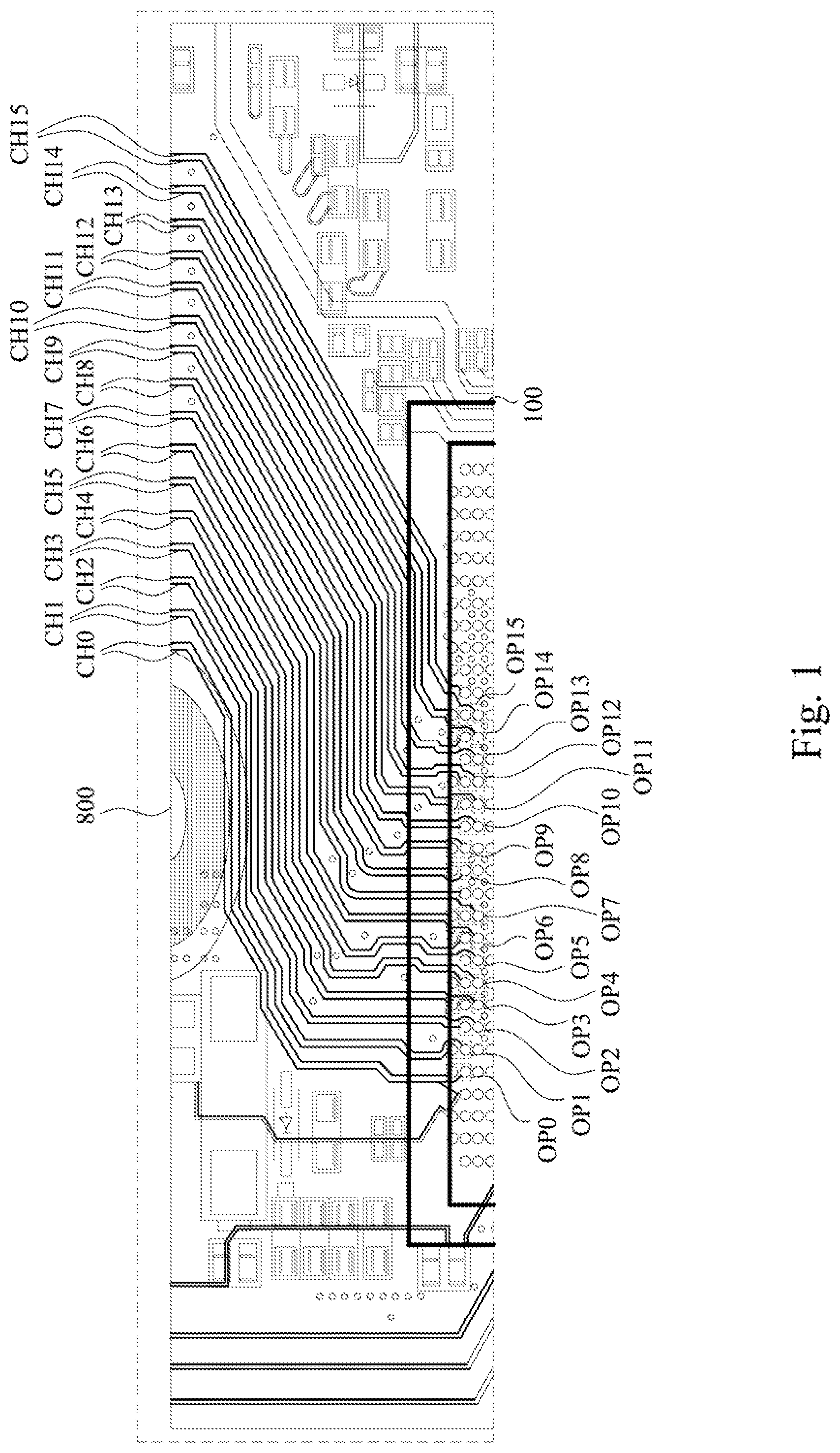
Reference is made to . is a schematic diagram illustrating an integrated circuit 100 according to some embodiments of the present disclosure. Take as an example, the integrated circuit 100 and the circuit board 800 couple to each other. In detail, the integrated circuit 100 includes several output terminals OP 0 to OP 15 , and the circuit board 800 includes several signal pair channels CH 0 to CH 15 . In some embodiments, the several output terminals OP 0 to OP 15 of the integrated circuit 100 are pins or balls. The several output terminals OP 0 to OP 15 of the integrated circuit 100 couple to several signal pair channels CH 0 to CH 15 of the circuit board 800 . The numbers of the output terminal and the signal pair channel as mentioned above is for illustrative purposes only, and the embodiments of the present disclosure are not limited thereto.
As illustrated in , several output terminals OP 0 to OP 15 and several signal pair channels CH 0 to CH 15 are connected one-to-one, and several output terminals OP 0 to OP 15 are connected via wires between each other. In detail, the output terminal OP 0 and the signal pair channel CH 0 are connected to each other, the output terminal OP 1 and the signal pair channel CH 1 are connected to each other, and so on. Furthermore, the output terminal OP 0 is configured to output signals to the signal pair channel CH 0 , the output terminal OP 1 is configured to output signals to the signal pair channel CH 1 , and so on.
As shown in , since there are many lines between several output terminals OP 0 to OP 15 and several signal pair channels CH 0 to CH 15 , at the junction between the integrated circuit 100 and the circuit board 800 , several signal pair channels CH 0 to CH 15 are prone to generate signal interference problems. The integrated circuit and the signal transmission method proposed in the embodiments of the present disclosure effectively solve the above problems.
Reference is made to . is a structural diagram illustrating an integrated circuit 100 according to some embodiments of the present disclosure. As illustrated in , the integrated circuit 100 includes a control circuit 110 and several output terminals OP 0 to OP 15 . The control circuit 110 is coupled to the several output terminals OP 0 to OP 15 . The integrated circuit 100 is coupled to the circuit board 800 through the connector 810 . In some embodiments, the control circuit 110 includes a multiplexer 112 .
The configuration of the integrated circuit 100 as mentioned above is for illustrative purposes only, several configuration of the integrated circuit 100 are within the scope of the present disclosure. The detailed operation method of the integrated circuit 100 will be explained with reference to below.
is a flow chart diagram illustrating a signal transmission method 300 according to some embodiments of the present disclosure. The signal transmission method 300 can be applied to the integrated circuit 100 as shown in and . Reference is made to to . In some embodiments, the signal transmission method 300 is operated by the control circuit 110 as illustrated in .
In operation S 310 , several output signals output to several signal pair channels by several output terminals of the integrated circuit is configured by the control circuit of the integrated circuit. For example, the output signals output to the signal pair channels CH 0 to CH 15 by the several output terminals OP 0 to OP 15 of the integrated circuit 100 is configured by the control circuit 110 of the integrated circuit 100 in .
In operation S 330 , several output signals are output by the several output terminals of the integrated circuit, so that the first signal pair channel and the second signal pair channel of the several signal pair channels receive and output several output signals, and the third signal pair channel of the several signal pair channels shields the interference between the first signal pair channel and the second signal pair channel.
In operation S 330 as mentioned above, the third signal pair channel is adjacent to the first signal pair channel and the second signal pair channel, and the third signal pair channel is located between the first signal pair channel and the second signal pair channel.
For example, the control circuit 110 of the integrated circuit 100 in configures the several output terminals OP 0 to OP 15 of the integrated circuit 100 to output the output signals. In some embodiments, reference is made to together. The output terminals OP 0 to OP 15 transmits the output signals to the signal pair channels CH 0 to CH 15 through the connector 810 .
For example, reference is made to together. is a schematic diagram illustrating a signal transmission according to some embodiments of the present disclosure. As illustrated in , the signal pair channel CH 4 is located between the signal pair channel CH 3 and the signal pair channel CH 5 , and the signal pair channel CH 4 is adjacent to the signal pair channel CH 3 and the signal pair channel CH 5 . In operation S 310 and operation S 330 , the control circuit 110 in configures the output terminal OP 3 to output the output signals to the signal pair channel CH 3 , and the control circuit 110 configures the output terminal OP 5 to output the output signals to the signal pair channel CH 5 . At the same time, the control circuit 110 configures the signal pair channel CH 4 to be a signal pair channel with a shield effect to shield the interference between the signal pair channel CH 3 and the signal pair channel CH 5 .
In some embodiments, the control circuit 110 in controls the output terminal OP 4 to output the shield signal to the output channel CH 4 , so that the output channel CH 4 has the shield effect.
In some embodiments, the shield signals include the high impedance obstructive state signals. In some embodiments, the shield signals include the direct current voltages.
In some embodiments, the control circuit 110 in configures the first part of the output terminals OP 0 to OP 15 to output the output signals to the first part of the signal pair channels CH 0 to CH 15 , and the control circuit 110 configures the second part of the output terminals OP 0 to OP 15 to not to output the output signals to the signal pair channel or to output the shield signals to the second part of the signal pair channels CH 0 to CH 15 , so that the second part of the signal pair channels CH 0 to CH 15 shields the interference between the first part of the signal pair channels CH 0 to CH 15 . The second part of the signal pair channels CH 0 to CH 15 , which is used as a shield, is intersected between the first part of the signal pair channels CH 0 to CH 15 .
In some embodiments, the first part of the signal pair channels CH 0 to CH 15 as mentioned above is used as a signal pair channel for general transmission, and the second part of the signal pair channels CH 0 to CH 15 is used as a signal pair channel for shield.
For example, reference is made to again. In , the signal pair channels CH 4 , CH 6 , CH 9 and CH 11 are used as signal pair channels for shield, while the signal pair channels CH 1 to CH 3 , CH 5 , CH 7 , CH 8 , CH 10 and CH 12 to CH 15 are used as signal pair channels for general output. The signal pair channels CH 1 to CH 3 , CH 5 , CH 7 , CH 8 , CH 10 , and CH 12 to CH 15 receive and transmit the output signals transmitted by the integrated circuit 100 . the signal pair channel CH 4 shields the interference between the signal pair channel CH 3 and the signal pair channel CH 5 , the signal pair channel CH 6 shields the interference between the signal pair channel CH 5 and the signal pair channel CH 7 , the signal pair channel CH 9 shields the interference between the signal pair channel CH 8 and the signal pair channel CH 10 , and the signal pair channel CH 11 shields the interference between the signal pair channel CH 10 and the signal pair channel CH 12 .
In some embodiments, as illustrated in , The integrated circuit 100 in further includes the ground wire G. The ground wire G extends from the integrated circuit 100 to the signal pair channels CH 7 and CH 8 and is adjacent to the signal pair channels CH 7 and CH 8 . The ground wire G is configured to shield the signal pair channels CH 7 and CH 8 .
In some embodiments, the control circuit 110 of the integrated circuit 100 in is further configured to select the first part of the output terminals according to the wire lengths of the signal pair channels to output the output signals to the first part of the signal pair channels, and to select the second part of the output terminals according to the wire lengths of the signal pair channels to output the output signals to the second part of the signal pair channels.
In some embodiments, the control circuit 110 determines that the signal pair channels with longer wire lengths need to be shielded to reduce interference, and the control circuit 110 configures the output signals so that the signal pair channels with longer wire lengths is adjacent to the signal pair channels used for shield. Furthermore, for the signal pair channel with the longest wire length or the signal pair channel closest to the center, the best shield effect can be achieved by setting the ground wire G.
For example, in the case of , it is assumed that the wire length of the signal pair channel closer to center C is longer. In this case, a ground wire G is configured between the signal pair channels CH 7 and CH 8 , which are closest to the center C. The signal pair channel CH 5 second closest to the center C is shielded through the signal pair channels CH 4 and CH 6 , and the signal pair channel CH 10 second closest to the center C is shielded through the signal pair channels CH 9 and CH 11 .
Reference is made to . is a schematic diagram illustrating a signal transmission between the integrated circuit and the circuit board according to some embodiments of the present disclosure. As illustrated in , the integrated circuit 100 ′ and the circuit board 800 ′ are connected to each other.
As illustrated in , the integrated circuit 100 ′ includes several pads P 0 to P 15 , the pads P 0 to P 15 are configured to serve as output signals to the output terminals OP 0 ′ to OP 15 ′ of the circuit board 800 ′. The circuit board 800 ′ includes the signal transmission interfaces 830 A and 830 B. The signal transmission interface 830 A includes 16 signal pair channel CHa 0 to CHa 15 . The signal transmission interface 830 B includes 12 signal pair channels CHb 0 to CHb 3 , CHb 5 , CHb 7 , CHb 8 , CHb 10 , and CHb 12 to CHb 15 .
In the connection relationship, the pad P 0 works as output terminal OP 0 ′ to output signals to the signal pair channel CHa 0 , and the pad P 1 works as output terminal OP 1 ′ to output signals to signal pair channel CHa 1 , and so on.
Since the number of the signal pair channels of the signal transmission interface 830 A is 16, compared with the number of signal pair channels of the signal transmission interface 830 B ( 12 ), the number of the signal pair channels of the signal transmission interface 830 A is larger, the control circuit 110 determines that there are 4 signal pair channels of the signal transmission interface 830 A that are not used or need not be used, so there are 4 signal pair channels that can be used as signal pair channels for the shield.
In some embodiments, the signal transmission interface 830 A is a VBY1 (V-by-One) interface, and the signal transmission interface 830 B is a CEDS (Clock Embedded Differential Signal) interface. The above interface is for illustrative purposes only, and the embodiments of the present disclosure are not limited thereto.
In , assume that the wire length of the signal pair channel closer to center C′ is longer. In this case, a ground wire G′ is configured to locate between the signal pair channels CHa 7 and CHa 8 , which are closest to the center C′, and the ground wire G′ is also configured to locate between the signal pair channels CHb 7 and CHb 8 , which are closest to the center C′. For the rest of the signal pair channels, the control circuit of the integrated circuit 100 ′ takes the signal pair channels CHa 4 , CHa 6 , CHa 9 and CHa 11 as signal pair channels with shield effect.
As illustrated in , the signal pair channel used as a shield and the signal pair channel used as a general transmission are intersected with each other, so as to shield the signal pair channel used for general transmission through the signal pair channel with a shield effect.
Take as an example. The signal pair channels CHa 0 to CHa 3 , CHa 5 , CHa 7 , CHa 8 , CHa 10 , CHa 12 to CHa 15 are signal pair channels for general transmission, and the signal pair channels CHa 4 , CHa 6 , CHa 9 , and CHa 11 are signal pair channels used as shields.
In the example of , limited by the number of signal pair channels, it is impossible to make all the signal pair channels used for general transmission to be intersected (or crossed) with the signal pair channels used as shield. The control circuit of the integrated circuit 100 ′ makes the signal pair channels CHa 3 , CHa 5 , and CHa 7 , which are closer to center C′ and are used as general transmission, intersect with the signal pair channels CHa 4 , CHa 6 , which are used as shields. Similarly, the control circuit of the integrated circuit 100 ′ makes the signal pair channels CHa 8 , CHa 10 , and CHa 12 , which are closer to the center C′ and are used as general transmission, intersect with the signal pair channels CHa 9 , CHa 11 , which are used as shields.
In signal transmission, the signal pair channel CHa 0 transmits the output signal to the signal pair channel CHb 0 , the signal pair channel CHa 1 transmits the output signal to the signal pair channel CHb 1 , and so on.
In some embodiments, the integrated circuit 100 makes the signal pair channel a signal pair channel for shielding by inputting high impedance obstructive state signal or direct current voltage to the signal pair channel.
In some embodiments, the signal pair channel CH 4 with shield effect is pulled to the ground through the pad of the integrated circuit 100 ′ and the multiplexer which is connected with the pad to increase the shield effect.
According to the above content, in some embodiments, based on the position of the signal pair channels CHa 0 to CHa 15 , CHb 0 to CHb 3 , CHb 5 , CHb 7 , CHb 8 , CHb 10 , CHb 12 to CHb 15 and the number of the signal pair channels CHa 0 to CHa 15 , CHb 0 to CHb 3 , CHb 5 , CHb 7 , CHb 8 , CHb 10 , CHb 12 to CHb 15 , the integrated circuit 100 ′ configures the output signals and outputs the output signals to the signal pair channels CHa 0 to CHa 15 , CHb 0 to CHb 3 , CHb 5 , CHb 7 , CHb 8 , CHb 10 , CHb 12 to CHb 15 .
Reference is made to . is a schematic diagram illustrating the multiplexer 112 as illustrated in according to some embodiments of the present disclosure. The multiplexer 112 shown in can transfer the output signals of each signal pair channel to any other signal pair channel. In detail, the output signal IS 0 originally outputs to the signal pair channel CH 0 can be transferred to be any one of the output signals OSO to OS 15 output to the signal pair channels CH 0 to CH 15 , and the output signal IS 1 can be transferred to be any one of the output signals OSO to OS 15 output to the signal pair channels CH 0 to CH 15 , and so on for the rest.
Through the setting of the multiplexer 112 , the control circuit 110 can output the output signals to the signal pair channels configured for general transmission according to the configuration of the integrated circuit 100 . In some embodiments, the multiplexer 112 outputs the output signals to the signal pair channels configured for general transmission among the signal pair channels.
Reference is made to and again. As illustrated in and , each of the signal pair channels CH 0 to CH 15 includes two sub signal pair channels. As shown in , each of the output terminals OP 0 to OP 15 includes two sub output terminals, and between the sub output terminals of the output terminals OP 0 to OP 15 and the sub signal pair channels of the signal pair channels CH 0 to CH 15 , the relationship is a one-to-one connection.
Reference is made to . In some embodiments, if that the width of the sub signal pair channel is W, the distance between the sub signal pair channels is 0.5 W, the distance between the two general transmission signal pair channels sandwiching the ground wire is 3 W, the distance between two signal pair channels for general transmission sandwiching the signal pair channel for shield is 4 W to 5 W, and the distance between two signal pair channels for general transmission with no ground wire and no signal pair channel for shield sandwiching between them is 1 W.
As illustrated in , there is no ground wire or shield between the signal pair channels CH 14 and CH 15 for general transmission, and the distance between the signal pair channels CH 14 and CH 15 is 1 W. The signal pair channels CH 8 and CH 10 for general transmission is sandwiching the signal pair channel CH 9 for shield, and the distance between the signal pair channels CH 8 and CH 10 is 4 W to 5 W. A ground wire is sandwiched between the signal pair channels CH 7 and CH 8 for general transmission, and the distance between the signal pair channels CH 7 and CH 8 is 3 W.
Furthermore, the distance between two sub signal pair channels of a signal pair channel is 0.5 W. For example, the distance between two sub signal pair channels of the signal pair channel CH 8 is 0.5 W.
It should be noted that, the distance between the signal pair channels is not limited to the above.
In some embodiments, the signal pair channel is a differential signal pair channel.
To sum up, the embodiments of the present disclosure provide an integrated circuit and a signal transmission method, by using the unused signal pair channel as the signal pair channel for the shield, the effect of reducing the interference between the signal pair channels can be achieved without increasing the line or ground wire. In addition, according to the number, positions and wire lengths of the signal pair channels, the signal pair channels for general transmission and the signal pair channels for shield can be used to reduce the interference between the signal pair channels more effectively.
In addition, it should be noted that in the operations of the above mentioned signal transmission method, no particular sequence is required unless otherwise specified. Moreover, the operations may also be performed simultaneously or the execution times thereof may at least partially overlap.
Although the present invention has been described in considerable detail with reference to certain embodiments thereof, other embodiments are possible. Therefore, the spirit and scope of the appended claims should not be limited to the description of the embodiments contained herein.
It will be apparent to those skilled in the art that various modifications and variations can be made to the structure of the present invention without departing from the scope or spirit of the invention. In view of the foregoing, it is intended that the present invention cover modifications and variations of this invention provided they fall within the scope of the following claims.
Figures (6)
Citations
This patent cites (6)
- US7609125
- US2004/0196112
- US2015/0282300
- US2019/0164891
- US202105140
- US202221490