Power Conversion Apparatus, Vehicle Auxiliary Power Supply, and Method for Stopping Power Conversion Apparatus
Abstract
A power conversion apparatus includes: a three-phase inverter that supplies alternating-current power obtained by conversion to a load via a filter circuit including a three-phase reactor circuit and a three-phase capacitor circuit; a voltage detector that detects three-phase voltages that are voltages at respective connection points between the three-phase reactor circuit and the three-phase capacitor circuit; and a control device that controls operation of the three-phase inverter on the basis of the three-phase voltages detected by the voltage detector. The control device includes a calculation unit that calculates a zero-phase voltage obtained by adding together the three-phase voltages, a separation unit that separates an instantaneous value of the zero-phase voltage into an alternating-current signal and a direct-current signal, and a first determination unit that determines whether a ground fault occurs on the basis of an effective value of the alternating-current signal.
Claims (14)
1. A power conversion apparatus comprising: a three-phase inverter to convert input power to alternating-current power and supply the alternating-current power obtained by conversion to a load via a filter circuit comprising a three-phase reactor circuit and a three-phase capacitor circuit; a voltage detector to detect three-phase voltages that are voltages at respective connection points between the three-phase reactor circuit and the three-phase capacitor circuit; and a control device to control operation of the three-phase inverter on a basis of the three-phase voltages detected by the voltage detector, wherein the control device comprises calculation circuitry to calculate a zero-phase voltage obtained by adding together the three-phase voltages, separation circuitry to separate an instantaneous value of the zero-phase voltage into an alternating-current signal and a direct-current signal, and first determination circuitry to determine whether a ground fault occurs on a basis of an effective value of the alternating-current signal.
13. A method for stopping a power conversion apparatus comprising a three-phase inverter to convert input power to alternating-current power and supply the alternating-current power obtained by conversion to a load via a filter circuit comprising a three-phase reactor circuit and a three-phase capacitor circuit, and a voltage detector to detect three-phase voltages that are voltages at respective connection points between the three-phase reactor circuit and the three-phase capacitor circuit, the method comprising: a calculation of calculating a zero-phase voltage obtained by adding together the three-phase voltages; a separation of separating an instantaneous value of the zero-phase voltage into an alternating-current signal and a direct-current signal; a first determination of determining whether a ground fault occurs on a basis of an effective value of the alternating-current signal; a zero-point detection of detecting a zero point of the zero-phase voltage on a basis of an instantaneous value of the zero-phase voltage; and stopping, when it is determined in the first determination that a ground fault occurs, operation of the three-phase inverter at a timing when the zero point is detected in the zero-point detection.
Show 12 dependent claims
2. The power conversion apparatus according to claim 1 , comprising second determination circuitry to determine whether a ground fault occurs on a basis of the direct-current signal.
3. The power conversion apparatus according to claim 2 , wherein the load is an alternating-current load to operate upon receiving supply of alternating-current power and a direct-current load to operate upon receiving supply of direct-current power, the first determination circuitry determines whether an alternating-current ground fault that possibly occurs on a power supply path to the alternating-current load occurs, and the second determination circuitry determines whether a direct-current ground fault that possibly occurs on a power supply path to the direct-current load occurs.
4. The power conversion apparatus according to claim 3 , wherein the control device includes zero-point detection circuitry to detect a zero point of the zero-phase voltage on a basis of the instantaneous value of the zero-phase voltage, and when the first determination circuitry determines that the ground fault occurs, the control device stops operation of the three-phase inverter at a timing when the zero point is detected by the zero-point detection circuitry.
5. A vehicle auxiliary power supply comprising: the power conversion apparatus according to claim 4 ; and the filter circuit, wherein the vehicle auxiliary power supply is mounted on a railroad vehicle, and uses direct-current power or alternating-current power supplied from an overhead line to supply the alternating-current power to an auxiliary load that is the load other than a main motor.
6. A vehicle auxiliary power supply comprising: the power conversion apparatus according to claim 3 ; and the filter circuit, wherein the vehicle auxiliary power supply is mounted on a railroad vehicle, and uses direct-current power or alternating-current power supplied from an overhead line to supply the alternating-current power to an auxiliary load that is the load other than a main motor.
7. The power conversion apparatus according to claim 2 , wherein the control device includes zero-point detection circuitry to detect a zero point of the zero-phase voltage on a basis of the instantaneous value of the zero-phase voltage, and when the first determination circuitry determines that the ground fault occurs, the control device stops operation of the three-phase inverter at a timing when the zero point is detected by the zero-point detection circuitry.
8. A vehicle auxiliary power supply comprising: the power conversion apparatus according to claim 7 ; and the filter circuit, wherein the vehicle auxiliary power supply is mounted on a railroad vehicle, and uses direct-current power or alternating-current power supplied from an overhead line to supply the alternating-current power to an auxiliary load that is the load other than a main motor.
9. A vehicle auxiliary power supply comprising: the power conversion apparatus according to claim 2 ; and the filter circuit, wherein the vehicle auxiliary power supply is mounted on a railroad vehicle, and uses direct-current power or alternating-current power supplied from an overhead line to supply the alternating-current power to an auxiliary load that is the load other than a main motor.
10. The power conversion apparatus according to claim 1 , wherein the control device includes zero-point detection circuitry to detect a zero point of the zero-phase voltage on a basis of the instantaneous value of the zero-phase voltage, and when the first determination circuitry determines that the ground fault occurs, the control device stops operation of the three-phase inverter at a timing when the zero point is detected by the zero-point detection circuitry.
11. A vehicle auxiliary power supply comprising: the power conversion apparatus according to claim 10 ; and the filter circuit, wherein the vehicle auxiliary power supply is mounted on a railroad vehicle, and uses direct-current power or alternating-current power supplied from an overhead line to supply the alternating-current power to an auxiliary load that is the load other than a main motor.
12. A vehicle auxiliary power supply comprising: the power conversion apparatus according to claim 1 ; and the filter circuit, wherein the vehicle auxiliary power supply is mounted on a railroad vehicle, and uses direct-current power or alternating-current power supplied from an overhead line to supply the alternating-current power to an auxiliary load that is the load other than a main motor.
14. The method for stopping the power conversion apparatus according to claim 13 , further comprising a second determination of determining whether a ground fault occurs on a basis of an absolute value of the direct-current signal, wherein when it is determined in the second determination that a ground fault occurs, the stopping includes performing a process of stopping operation of the three-phase inverter regardless of whether the zero point is detected in the zero-point detection.
Full Description
Show full text →
FIELD
The present invention relates to a power conversion apparatus that converts input power into alternating-current power and supplies the alternating-current power to a load, to a vehicle auxiliary power supply including the power conversion apparatus, and to a method for stopping the power conversion apparatus.
BACKGROUND
Patent Literature 1 described below discloses a vehicle auxiliary power supply configured to convert high-voltage direct-current power input from a pantograph into alternating-current power by a three-phase inverter, supply the alternating-current power output from the three-phase inverter to a transformer via an alternating-current reactor, and convert the alternating-current power into desired low-voltage alternating-current power by the transformer.
The vehicle auxiliary power supply supplies power to an auxiliary load. The auxiliary load refers to a load other than a main motor among the loads mounted on a railroad vehicle. Examples of the auxiliary load include a vehicle interior lighting device, a door opening and closing device, an air conditioner, a safety device, a compressor, a battery, and a control power supply. The compressor is a device that generates air source for a vehicle brake.
A typical vehicle auxiliary power supply includes an overcurrent detector. The overcurrent detector detects overcurrent flowing in an auxiliary load circuit. The auxiliary load circuit is an electrical circuit for supplying power to an auxiliary load from a three-phase inverter. When the overcurrent detector detects overcurrent, the vehicle auxiliary power supply performs a protection operation of stopping operation of the three-phase inverter.
CITATION LIST
Patent Literature
Patent Literature 1: Japanese Patent Application Laid-open No. 2011-211777
SUMMARY
Technical Problem
Because the auxiliary load is mounted on a railroad vehicle, insulation deterioration of the auxiliary load develops earlier than that of home appliances or the like. If the insulation deterioration develops, the current flowing in the auxiliary load circuit becomes larger than that in the case when the insulation deterioration has not occurred. Here, the current flowing in the auxiliary load circuit when the insulation deterioration occurs is referred to as “ground fault current”. The ground fault current is smaller than the overcurrent described above. Thus, the ground fault current rarely reaches a determination value for overcurrent protection; therefore, the insulation deterioration of the auxiliary load circuit is difficult to detect with high accuracy. Although it is possible to lower the determination value for overcurrent protection, the number of false positives in overcurrent protection increases, which is a practical problem.
The present invention has been achieved in view of the above and an object of the present invention is to provide a power conversion apparatus capable of detecting insulation deterioration of an auxiliary load circuit early with high accuracy.
Solution to Problem
In order to solve the above problems and achieve the object, a power conversion apparatus according to the present invention includes a three-phase inverter to convert input power to alternating-current power and supply the alternating-current power obtained by conversion to a load via a filter circuit comprising a three-phase reactor circuit and a three-phase capacitor circuit. The power conversion apparatus further includes a voltage detector to detect three-phase voltages that are voltages at respective connection points between the three-phase reactor circuit and the three-phase capacitor circuit, and a control device to control operation of the three-phase inverter on a basis of the three-phase voltages detected by the voltage detector. The control device includes a calculation unit to calculate a zero-phase voltage obtained by adding together the three-phase voltages, a separation unit to separate an instantaneous value of the zero-phase voltage into an alternating-current signal and a direct-current signal, and a first determination unit to determine whether a ground fault occurs on a basis of an effective value of the alternating-current signal.
Advantageous Effects of Invention
According to the present invention, an effect is obtained where insulation deterioration of an auxiliary load circuit can be detected early with high accuracy.
BRIEF DESCRIPTION OF DRAWINGS
is a diagram illustrating an exemplary configuration of a vehicle auxiliary power supply according to an embodiment.
is a diagram illustrating a first exemplary configuration of a power supply that generates input power for the three-phase inverter illustrated in .
is a diagram illustrating a second exemplary configuration of the power supply that generates input power for the three-phase inverter illustrated in .
is a first diagram used for explaining the principle of ground fault detection according to the present embodiment.
is a second diagram used for explaining the principle of ground fault detection according to the present embodiment.
is a third diagram used for explaining the principle of ground fault detection according to the present embodiment.
is a diagram illustrating an exemplary configuration of a control device according to the present embodiment.
is a diagram illustrating an exemplary configuration of a zero-phase voltage calculation unit illustrated in .
is a diagram illustrating an exemplary configuration of a ground fault detection unit illustrated in .
is a flowchart illustrating a flow of a process by the control device in the present embodiment.
is a block diagram illustrating an example of a hardware configuration when the function of the control device according to the present embodiment is implemented by software.
is a block diagram illustrating another example of a hardware configuration when the function of the control device according to the present embodiment is implemented by software.
DESCRIPTION OF EMBODIMENTS
A power conversion apparatus, a vehicle auxiliary power supply, and a method for stopping the power conversion apparatus according to embodiments of the present invention will be described below in detail with reference to the accompanying drawings. Note that the embodiments described below are not intended to limit the present invention. Moreover, the embodiments below will be described in terms of a power conversion apparatus mounted on a railroad vehicle as an example; however, this is not intended to exclude applications to other uses. Moreover, in the following descriptions, electrical connection and physical connection are not distinguished from each other and are simply referred to as “connection”.
Embodiment
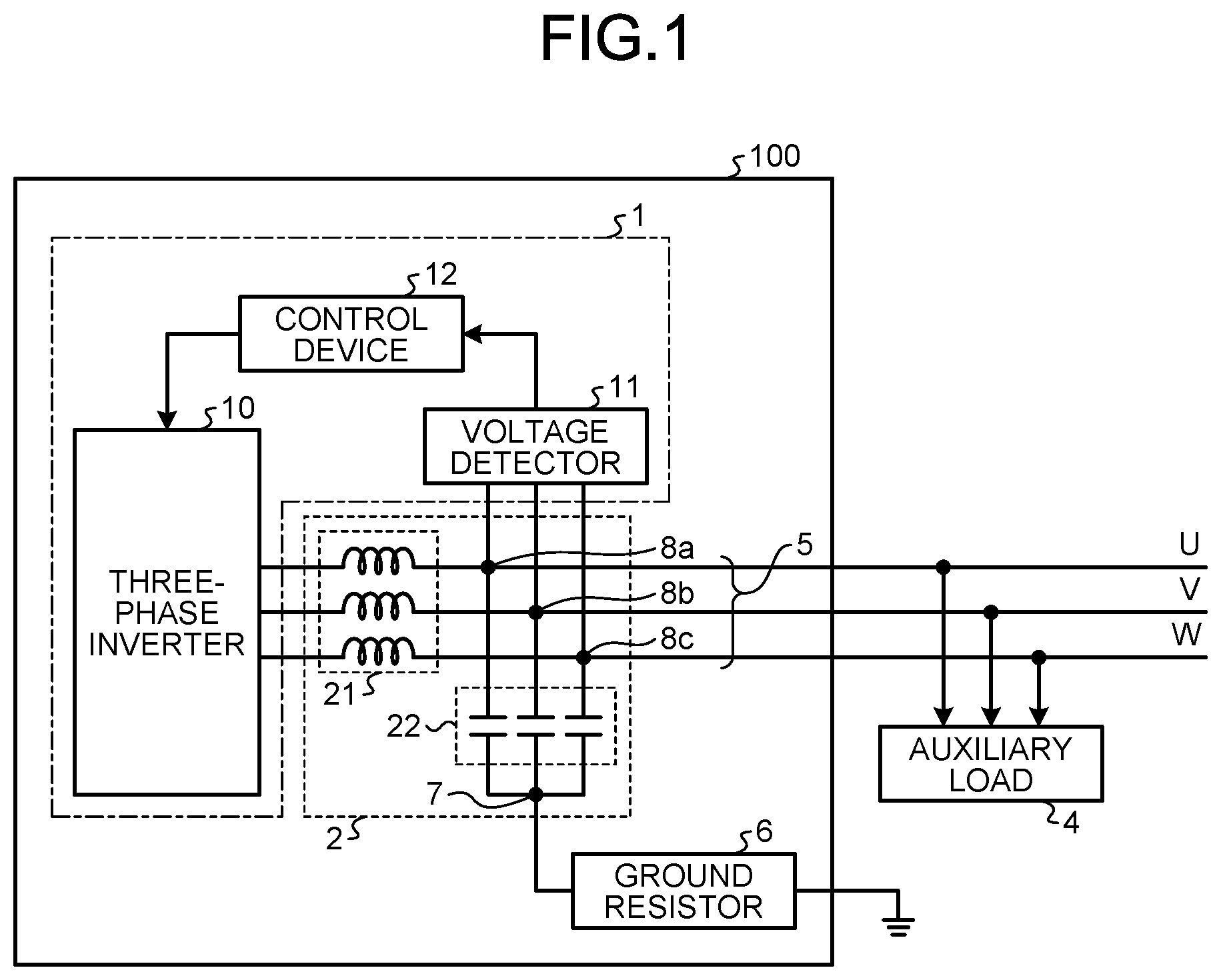
is a diagram illustrating an exemplary configuration of a vehicle auxiliary power supply 100 according to an embodiment. As illustrated in , the vehicle auxiliary power supply 100 according to the present embodiment includes a power conversion apparatus 1 and a filter circuit 2 . The power conversion apparatus 1 includes a three-phase inverter 10 , a voltage detector 11 , and a control device 12 . The three-phase inverter 10 and an auxiliary load 4 are connected with each other by three electrical wires 5 with the filter circuit 2 therebetween. The three electrical wires 5 are U-phase, V-phase, and W-phase electrical wires.
The filter circuit 2 includes a three-phase reactor circuit 21 and a three-phase capacitor circuit 22 . The three-phase reactor circuit 21 includes three reactor elements. The three-phase capacitor circuit 22 includes three capacitor elements. Each of the three reactor elements of the three-phase reactor circuit 21 is inserted into the corresponding U-phase, V-phase, or W-phase electrical wire 5 . One end of each of the three reactor elements is connected to the three-phase inverter 10 . The other end of each of the three reactor elements is connected to one end of a corresponding one of the capacitor elements of the three-phase capacitor circuit 22 at a connection point 8 a , 8 b , or 8 c on the electrical wire 5 . The other ends of the three capacitor elements are connected with each other at one point. This connection is referred to as Y-connection. A connection point 7 that is a connection point in the Y-connection configuration is grounded via a ground resistor 6 . The three-phase reactor circuit 21 and the three-phase capacitor circuit 22 constitute an LC filter circuit.
As described above, examples of the auxiliary load 4 include a vehicle interior lighting device, a door opening and closing device, an air conditioner, a safety device, a compressor, a battery, and a control power supply. Of the examples of the auxiliary load 4 , a vehicle interior lighting device, a door opening and closing device, an air conditioner, a safety device, and a compressor are alternating-current (AC) loads that operate upon receiving supply of AC power. A battery and a control power supply are direct-current (DC) loads that operate upon receiving supply of DC power.
As illustrated in , the voltage detector 11 detects three-phase voltages appearing at the connection points 8 a , 8 b , and 8 c . In other words, the three-phase voltages are voltages at respective connection points between the three-phase reactor circuit 21 and the three-phase capacitor circuit 22 . The result of detection by the voltage detector 11 is input to the control device 12 . The control device 12 controls operation of the three-phase inverter 10 on the basis of the three-phase voltages detected by the voltage detector 11 .
In , the voltage detector 11 detects the voltages at the connection points 8 a , 8 b , and 8 c between the three-phase reactor circuit 21 and the three-phase capacitor circuit 22 ; however, the present embodiment is not limited thereto. Voltage may be detected at points displaced toward the three-phase reactor circuit 21 or toward the auxiliary load 4 from the connection points 8 a , 8 b , and 8 c in . In other words, the voltage detector 11 may detect voltage at any position that is regarded as having the same potential as the potential at each connection point.
The three-phase inverter 10 converts input power into AC power and supplies the AC power obtained by the conversion to the auxiliary load 4 via the filter circuit 2 under the control of the control device 12 . The filter circuit 2 reduces harmonics contained in the output voltage of the three-phase inverter 10 . Thus, AC voltage having a more sinusoidal shape than that when there is no filter circuit 2 is applied to the auxiliary load 4 .
is a diagram illustrating a first exemplary configuration of a power supply that generates input power for the three-phase inverter 10 illustrated in . In the first exemplary configuration illustrated in , DC power supplied from a DC overhead line 30 is received via a current collector 31 . The DC power received is converted into AC power by a single-phase inverter 50 . The AC power obtained by the conversion is stepped down by a transformer 52 and is then supplied to a single-phase converter 61 . The AC power stepped down is converted into DC power by the single-phase converter 61 and is then supplied to the three-phase inverter 10 .
is a diagram illustrating a second exemplary configuration of the power supply that generates input power for the three-phase inverter 10 illustrated in . In the second exemplary configuration illustrated in , the DC overhead line 30 is replaced by an AC overhead line 30 A and the current collector 31 for DC overhead line is replaced by a current collector 31 A for AC overhead line. Moreover, comparing the configuration illustrated in with the configuration illustrated in , a transformer 41 and a single-phase converter 42 are arranged in this order between the current collector 31 A and the single-phase inverter 50 in . The AC power supplied from the AC overhead line 30 A is received by the transformer 41 via the current collector 31 A. The AC power received is stepped down by the transformer 41 and is then supplied to the single-phase converter 42 . The AC power stepped down is converted into DC power by the single-phase converter 42 and is then supplied to the single-phase inverter 50 . The subsequent operations are the same as those in . Although the single-phase inverter 50 , the transformer 52 , and the single-phase converter 61 that are common components are each denoted by the same reference numeral in and , it is needless to say that the capacity or a system of each component is different depending on the difference in overhead line voltage.
is a first diagram used for explaining the principle of ground fault detection according to the present embodiment. is a second diagram used for explaining the principle of ground fault detection according to the present embodiment. is an example of a case where the auxiliary load 4 connected to the vehicle auxiliary power supply 100 in is an AC load 4 A. In , an example is illustrated where insulation of a W-phase electrical wire deteriorates and a W-phase ground fault has occurred. In , the phase relation between three-phase voltages Vu, Vv, and Vw output from the three-phase inverter 10 is represented by vectors. In this specification, a ground fault that occurs when the auxiliary load 4 is the AC load 4 A is referred to as “AC ground fault”.
When there is no ground fault, as illustrated in , the three-phase voltages Vu, Vv, and Vw have such a phase relation that they are 120° out of phase with each other. When the three-phase voltages have such a phase relation that they are 120° out of phase with each other, the sum of the three-phase voltages Vu, Vv, and Vw indicating a zero-phase voltage, or zero-sequence voltage, is zero. That is, there is a relation Vu+Vv+Vw=0.
The connection point 7 is a point of interconnection and thus has a common potential. Thus, the three-phase voltages Vu, Vv, and Vw are applied to the respective capacitors of the three-phase capacitor circuit 22 . This means that when there is no ground fault, a zero-phase voltage does not appear at the connection point 7 . In contrast, when an AC ground fault has occurred, the value of the zero-phase voltage Vu+Vv+Vw does not become zero and the zero-phase voltage that changes with a period of three-phase voltage as illustrated in a broken-line frame in appears at the connection point 7 .
is a third diagram used for explaining the principle of ground fault detection according to the present embodiment. is an example of a case where the auxiliary load 4 connected to the vehicle auxiliary power supply 100 in is a DC load 4 B. The DC load 4 B is connected to the electrical wires 5 via a rectifier 9 . In , an example is illustrated where insulation of the electrical wires provided between the rectifier 9 and the DC load 4 B deteriorates and a ground fault has occurred in one of the electrical wires. In this specification, a ground fault that occurs when the auxiliary load 4 is the DC load 4 B is referred to as “DC ground fault”. In the case of the DC ground fault as well, voltage appears at the connection point 7 in a similar manner to the case of the AC ground fault. Note that, voltage that appears in the case of the DC ground fault is DC voltage.
Next, a description will be given of configuration and operation of the control device 12 according to the present embodiment. is a diagram illustrating an exemplary configuration of the control device 12 according to the present embodiment. As illustrated in , the control device 12 in the present embodiment includes a zero-phase voltage calculation unit 121 and a ground fault detection unit 122 . is a diagram illustrating an exemplary configuration of the zero-phase voltage calculation unit 121 illustrated in . As illustrated in , the zero-phase voltage calculation unit 121 includes an adder 121 a . In the following descriptions, the zero-phase voltage calculation unit 121 is in some cases simply referred to as “calculation unit”.
The three-phase voltages Vu, Vv, and Vw detected by the voltage detector 11 are input to the zero-phase voltage calculation unit 121 . The adder 121 a adds together the three-phase voltages Vu, Vv, and Vw to calculate a zero-phase voltage V 0 . The zero-phase voltage V 0 calculated is output to the ground fault detection unit 122 .
is a diagram illustrating an exemplary configuration of the ground fault detection unit 122 illustrated in . As illustrated in , the ground fault detection unit 122 includes an AC/DC separation unit 122 a , an effective value calculation unit 122 b , an absolute value calculation unit 122 c , comparators 122 d , 122 e , and 122 g , an AND operation unit 122 f , and an OR operation unit 122 h . In the following descriptions, the AC/DC separation unit 122 a is in some cases simply referred to as “separation unit”.
The zero-phase voltage V 0 calculated by the zero-phase voltage calculation unit 121 is input to the AC/DC separation unit 122 a . The AC/DC separation unit 122 a separates the instantaneous value of the zero-phase voltage V 0 into an AC component and a DC component. The AC component of the signal separated by the AC/DC separation unit 122 a is referred to as AC signal and is denoted by “a 1 ”. The DC component of the signal separated by the AC/DC separation unit 122 a is referred to as DC signal and is denoted by “d 1 ”. The AC signal a 1 can be generated by a high-pass filtering process, a band-pass filtering process, or the like. The DC signal d 1 can be generated by a low-pass pass filtering process or the like. The AC signal a 1 is input to the effective value calculation unit 122 b and the comparator 122 e . The DC signal d 1 is input to the absolute value calculation unit 122 c.
The effective value calculation unit 122 b calculates an effective value a 2 of the AC signal a 1 . The effective value a 2 calculated is input to the comparator 122 d . The comparator 122 d compares the effective value a 2 with a determination value 1 , and outputs a comparison result a 3 thereof. The comparison result a 3 is a logical value. When the effective value a 2 is larger than the determination value 1 , logic “1” is output. When the effective value a 2 is smaller than or equal to the determination value 1 , logic “0” is output.
In the present embodiment, the effective value calculation unit 122 b and the comparator 122 d constitute a first determination unit. With the function described above, the first determination unit can determine whether an AC ground fault that may occur on the power supply path to the AC load 4 A has occurred.
The absolute value calculation unit 122 c calculates an absolute value d 2 of the DC signal d 1 . The absolute value d 2 is input to the comparator 122 g . The comparator 122 g compares the absolute value d 2 with a determination value 2 , and outputs a comparison result d 3 thereof. The comparison result d 3 is a logical value. When the absolute value d 2 is larger than the determination value 2 , logic “1” is output. When the absolute value d 2 is smaller than or equal to the determination value 2 , logic “0” is output.
In the present embodiment, the absolute value calculation unit 122 c and the comparator 122 g constitute a second determination unit. With the function described above, the second determination unit can determine whether a DC ground fault that may occur on the power supply path to the DC load 4 B has occurred.
The comparator 122 e compares the AC signal a 1 with a determination value 3 , and outputs a comparison result a 4 thereof. The comparison result a 4 is a logical value. When the AC signal a 1 is larger than the determination value 3 , logic “1” is output. When the AC signal a 1 is smaller than or equal to the determination value 3 , logic “0” is output. The determination value 3 is a determination value for detecting an instantaneous-value zero point illustrated in .
The comparison result a 3 from the comparator 122 d and the comparison result a 4 from the comparator 122 e are input to the AND operation unit 122 f . The AND operation unit 122 f performs an AND operation on the comparison results a 3 and a 4 . When both the comparison results a 3 and a 4 are logic “1”, logic “1” is output. In contrast, when at least one of the comparison results a 3 and a 4 is logic “0”, logic “0” is output.
A calculation result a 5 from the AND operation unit 122 f and the comparison result d 3 from the comparator 122 g are input to the OR operation unit 122 h . The OR operation unit 122 h performs an OR operation S 1 on the calculation result a 5 and the comparison result d 3 . When at least one of the calculation result a 5 and the comparison result d 3 is logic “1”, logic “1” is output. In contrast, when both the calculation result a 5 and the comparison result d 3 are logic “0”, logic “0” is output.
In the present embodiment, the comparator 122 e and the AND operation unit 122 f constitute a zero-point detection unit. The zero-point detection unit can detect a zero point of the zero-phase voltage in the AC ground fault on the basis of the instantaneous value of the zero-phase voltage. With the function of the zero-point detection unit and the function of the first determination unit, when the first determination unit determines that a ground fault has occurred, the control device 12 can stop the operation of the three-phase inverter 10 at the timing when a zero point is detected by the zero-point detection unit.
Next, a description will be given of a mode of control by the control device 12 according to the first embodiment. First, the control device 12 monitors the zero-phase voltage calculated by using three-phase voltages that are voltages at the respective connection points between the three-phase reactor circuit 21 and the three-phase capacitor circuit 22 . In the auxiliary load circuit, when an AC ground fault occurs, the zero-phase voltage is generated. With the use of this principle, the control device 12 performs a threshold-based determination on the effective value of the AC component of the zero-phase voltage, and determines that an AC ground fault has occurred when the effective value is larger than the threshold value.
The auxiliary load 4 connected to the vehicle auxiliary power supply 100 is generally an AC load but may be a DC load. As a method for determining the occurrence of a DC ground fault, it is possible to use a control circuit for determining the occurrence of an AC ground fault. This method however has trouble with accuracy of the determination. Thus, a control circuit for determining the occurrence of a DC ground fault is separately provided. In the auxiliary load circuit including a DC load, when a DC ground fault has occurred, the zero-phase voltage is generated in a similar manner to the case of an AC ground fault. The control device 12 performs a threshold-based determination on the absolute value of the DC component of the zero-phase voltage, and determines that a DC ground fault has occurred when the absolute value is larger than the threshold value.
When an AC ground fault or a DC ground fault has occurred, the control device 12 stops the operation of the vehicle auxiliary power supply 100 and stops supplying power to the auxiliary load 4 . In this case, the voltage in the case of three-phase imbalance may remain in the three-phase capacitor circuit 22 as a residual voltage depending on the timing of stopping the operation of the vehicle auxiliary power supply 100 . The residual voltage may adversely affect the operation of the auxiliary load 4 when the vehicle auxiliary power supply 100 is restarted. Thus, the timing of stopping the operation of the vehicle auxiliary power supply 100 is controlled such that the residual voltage is as close to zero as possible. Specifically, as described above, the control device 12 stops the operation of the three-phase inverter 10 at the timing when a zero point of the zero-phase voltage is detected. With this control, the residual voltage of the three-phase capacitor circuit 22 is in the same state as that in the case of three-phase equilibrium; therefore, the residual voltage can be controlled such that it has a value close to zero.
and are examples of a case when the functions of the zero-phase voltage calculation unit 121 and the ground fault detection unit 122 illustrated in are implemented by a control circuit; however, the present embodiment is not limited to these examples. The function of the control device 12 according to the present embodiment can be represented in the form of a flowchart. is a flowchart illustrating a flow of a process by the control device 12 in the present embodiment.
The control device 12 calculates a zero-phase voltage (step S 101 ). The control device 12 separates the zero-phase voltage into an AC signal that is a signal train of the AC component and a DC signal that is a signal train of the DC component by using calculation data of the zero-phase voltage for at least one or more periods (step S 102 ). The AC signal is used in the process in step S 103 and the subsequent steps and the DC signal is used in the process in step 105 and the subsequent steps. These processes are performed concurrently under the control of the control device 12 .
Process for AC Signal
The control device 12 calculates the effective value of the AC signal (step S 103 ). The control device 12 compares the effective value calculated in step S 103 with the determination value 1 (step S 104 ). When the effective value is smaller than the determination value 1 (No in step S 104 ), the process returns to step S 101 . Thereafter, the process from step S 101 is repeated. When the effective value is larger than or equal to the determination value 1 (Yes in step S 104 ), the control device 12 detects a zero point of the zero-phase voltage (step S 107 ). Then, the control device 12 stops the operation of the vehicle auxiliary power supply 100 at the timing when the zero point of the zero-phase voltage is detected (step S 108 ) and ends the process flow in .
In the process in step S 104 described above, “Yes” is determined when the effective value is equal to the determination value 1 , but “No” may be determined in such a case. That is, either “Yes” or “No” may be determined when the effective value is equal to the determination value 1 .
Process for DC Signal
The control device 12 calculates the absolute value of the DC signal (step S 105 ). The control device 12 compares the absolute value calculated in step S 105 with the determination value 3 (step S 106 ). When the absolute value is smaller than the determination value 3 (No in step S 106 ), the process returns to step S 101 . Thereafter, the process from step S 101 is repeated. When the absolute value is larger than or equal to the determination value 3 (Yes in step S 106 ), the control device 12 immediately stops the operation of the vehicle auxiliary power supply 100 (step S 108 ) and ends the process flow in . In the case of the DC signal, a voltage zero point is not generated. Thus, the operation of the vehicle auxiliary power supply 100 is immediately stopped unlike the process in the case of the AC signal.
In the process in step S 106 described above, “Yes” is determined when the absolute value is equal to the determination value 3 , but “No” may be determined in such a case. That is, either “Yes” or “No” may be determined when the absolute value is equal to the determination value 3 .
In the following descriptions, in some cases, the process in step S 101 is referred to as “calculation step” and the process in step S 102 is referred to as “separation step”. Moreover, in some cases, the process in step S 104 is referred to as “first determination step” and the process in step S 106 is referred to as “second determination step”. Moreover, in some cases, the process in step S 107 is referred to as “zero point detection step” and the process in step S 108 is referred to as “stopping step”.
Next, a description will be given of a hardware configuration for implementing the function of the control device 12 according to the present embodiment by software with reference to and . is a block diagram illustrating an example of a hardware configuration when the function of the control device 12 according to the present embodiment is implemented by software. is a block diagram illustrating another example of a hardware configuration when the function of the control device 12 according to the present embodiment is implemented by software.
In the case where the functions of the zero-phase voltage calculation unit 121 and the ground fault detection unit 122 in the control device 12 described above are implemented by software, as illustrated in , the configuration may be such that a processor 300 that performs an arithmetic operation, a memory 302 that saves programs to be read by the processor 300 , and an interface 304 that inputs and outputs signals are included.
The processor 300 may be arithmetic means such as an arithmetic unit, a microprocessor, a microcomputer, a central processing unit (CPU), or a digital signal processor (DSP). The memory 302 can be exemplified by a non-volatile or volatile semiconductor memory such as a random access memory (RAM), a read only memory (ROM), a flash memory, an erasable programmable ROM (EPROM), or an electrically EPROM (EEPROM (registered trademark)), a magnetic disk, a flexible disk, an optical disk, a compact disc, a mini disc, and a digital versatile disc (DVD).
The memory 302 stores a program for implementing the functions of the zero-phase voltage calculation unit 121 and the ground fault detection unit 122 . The processor 300 exchanges necessary information via the interface 304 and executes the program stored in the memory 302 , thereby enabling the functions of the zero-phase voltage calculation unit 121 and the ground fault detection unit 122 described above to be executed.
The processor 300 and the memory 302 illustrated in may be replaced by processing circuitry 303 as illustrated in . The processing circuitry 303 corresponds to a single circuit, a composite circuit, an application specific integrated circuit (ASIC), a field-programmable gate array (FPGA), or a combination thereof.
As described above, according to the present embodiment, the control device calculates a zero-phase voltage obtained by adding together three-phase voltages that are voltages at respective connection points between the three-phase reactor circuit and the three-phase capacitor circuit. The control device then separates the instantaneous value of the zero-phase voltage calculated into an AC signal and a DC signal and determines whether a ground fault has occurred on the basis of the effective value of the AC signal separated. The ground fault current flowing in the auxiliary load circuit when insulation deterioration has occurred is small. Thus, with the method of directly detecting the ground fault current, it is difficult to detect whether a ground fault has occurred with high accuracy. In contrast, the present embodiment applies a method in which three-phase voltages are used that are voltages at respective connection points between the three-phase reactor circuit and the three-phase capacitor circuit. With this method, the accuracy of detecting a ground fault can be improved compared with the method of directly detecting the ground fault current. Therefore, insulation deterioration of the auxiliary load circuit can be detected with high accuracy.
Moreover, according to the present embodiment, the control device determines whether a ground fault has occurred by using a determination logic different from overcurrent protection. Thus, it is possible to use a determination value different from overcurrent protection and specialized for the determination of whether a ground fault has occurred. Therefore, insulation deterioration of the auxiliary load circuit can be detected early.
Moreover, according to the present embodiment, the control device detects a zero point of the zero-phase voltage on the basis of the instantaneous value of the zero-phase voltage. When an AC ground fault is detected, the control device performs control of stopping the operation of the three-phase inverter at the timing when the zero point of the zero-phase voltage is detected. With this control, the residual voltage of the three-phase capacitor circuit can be controlled such that it becomes a value close to zero. Therefore, the adverse effect on the operation of the auxiliary load when the vehicle auxiliary power supply is restarted can be reduced.
The configurations described in the above-mentioned embodiments are merely examples of the content of the present invention. These configurations can be combined with another known technology, and moreover, a part of such configurations can be omitted and/or modified without departing from the scope of the present invention.
For example, illustrates the exemplary configuration in which the connection point 7 of the three-phase capacitor circuit 22 is grounded via the ground resistor 6 ; however, the present embodiment is not limited to this configuration. If the resistance value of the electrical wires for grounding the connection point 7 satisfies the electrical equipment technical standards, the connection point 7 may be grounded without passing through the ground resistor 6 .
Moreover, although illustrates the example configuration in which the three capacitor elements of the three-phase capacitor circuit 22 are star-connected, the present embodiment is not limited to this configuration. The three capacitor elements may be delta-connected. When the three capacitor elements are delta-connected, the typical configuration is such that the three-phase inverter 10 and the three-phase capacitor circuit 22 are connected via a Δ-Y transformer. In the case of this configuration, the midpoint of the secondary-side coil of a transformer (not illustrated) is grounded. Therefore, the voltage of the midpoint of the secondary-side coil can be detected and the method according to the present embodiment described above can be applied.
Reference Signs List
1 power conversion apparatus; 2 filter circuit; 4 auxiliary load; 4 A AC load; 4 B DC load; 5 electrical wire; 6 ground resistor; 7 , 8 a , 8 b , 8 c connection point; 9 rectifier; 10 three-phase inverter; 11 voltage detector; 12 control device; 21 three-phase reactor circuit; 22 three-phase capacitor circuit; 30 DC overhead line; 30 A AC overhead line; 31 , 31 A current collector; 41 , 52 transformer; 42 , 61 single-phase converter; 50 single-phase inverter; 100 vehicle auxiliary power supply; 121 zero-phase voltage calculation unit; 121 a adder; 122 ground fault detection unit; 122 a AC/DC separation unit; 122 b effective value calculation unit; 122 c absolute value calculation unit; 122 d , 122 e , 122 g comparator; 122 f AND operation unit; 122 h OR operation unit; 300 processor; 302 memory; 303 processing circuitry; 304 interface.
Figures (8)
Citations
This patent cites (7)
- US2013/0314013
- US2016/0094180
- US2018/0045767
- US2019/0312425
- US2011211777
- US2013-247754
- US2017-103902