Device, Method, and Graphical User Interface for Annotating Content
Abstract
A method includes displaying, on a display, first content and a representation of second content associated with the first content. The method includes detecting, via one or more input devices, a user input at a location of the representation of the second content. The method includes, in response to detecting the user input at the location of the representation of the second content, in accordance with a determination that the user input includes a stylus contact, displaying, on the display, a drawing user interface including the second content and a toolbar region with a plurality of drawing tool selection affordances. The method includes, in response to detecting the user input at the location of the representation of the second content, in accordance with a determination that the user input does not include a stylus contact, forgoing display of the drawing user interface.
Claims (21)
1. A method comprising: at an electronic device with one or more processors, non-transitory memory, a display, and one or more input devices: displaying, on the display, first content and a representation of second content associated with the first content; while displaying the first content and the representation of the second content, detecting, via the one or more input devices, a first user input at a location of the representation of the second content; in response to detecting the first user input at the location of the representation of the second content, displaying, on the display, a first user interface including the second content; while displaying the first user interface including the second content, detecting, via the one or more input devices, a second user input at a location of the second content; in response to detecting the second user input at the location of the second content: in accordance with a determination that the second user input includes a stylus contact, displaying, on the display, a drawing user interface including the second content and a toolbar region with a plurality of drawing tool selection affordances; and in accordance with a determination that the second user input does not include a stylus contact, forgoing display of the drawing user interface, wherein forgoing display of the drawing user interface includes displaying a third user interface including the second content without the plurality of drawing tool selection affordances.
7. An electronic device comprising: a display; one or more input devices; and one or more processors configured to: display, on the display, first content and a representation of second content associated with the first content; while displaying the first content and the representation of the second content, detect, via the one or more input devices, a first user input at a location of the representation of the second content; in response to detecting the first user input at the location of the representation of the second content, display, on the display, a first user interface including the second content; while displaying the first user interface including the second content, detect, via the one or more input devices, a second user input at a location of the second content; in response to detecting the second user input at the location of the second content: in accordance with a determination that the second user input includes a stylus contact, display, on the display, a drawing user interface including the second content and a toolbar region with a plurality of drawing tool selection affordances; and in accordance with a determination that the second user input does not include a stylus contact, forgo display of the drawing user interface, wherein forgoing display of the drawing user interface includes displaying a third user interface including the second content without the plurality of drawing tool selection affordances.
13. A non-transitory computer-readable storage medium storing one or more programs, the one or more programs comprising instructions, which, when executed by an electronic device with a display and one or more input devices, cause the electronic device to: display, on the display, first content and a representation of second content associated with the first content; while displaying the first content and the representation of the second content, detect, via the one or more input devices, a first user input at a location of the representation of the second content; in response to detecting the first user input at the location of the representation of the second content, display, on the display, a first user interface including the second content; while displaying the first user interface including the second content, detect, via the one or more input devices, a second user input at a location of the second content; in response to detecting the second user input at the location of the second content: in accordance with a determination that the second user input includes a stylus contact, display, on the display, a drawing user interface including the second content and a toolbar region with a plurality of drawing tool selection affordances; and in accordance with a determination that the second user input does not include a stylus contact, forgo display of the drawing user interface, wherein forgoing display of the drawing user interface includes displaying a third user interface including the second content without the plurality of drawing tool selection affordances.
Show 18 dependent claims
2. The method of claim 1 , wherein the second content includes an image, wherein the second user input defines a path from a first location within the image to a second location within the image, and wherein displaying the drawing user interface including the second content further includes displaying a drawing object corresponding to the path.
3. The method of claim 2 , wherein the second content includes an increased-scale version of the image, wherein the drawing object corresponding to the path includes an increased-scale version of the path.
4. The method of claim 2 , wherein the second content includes an increased-scale version of the image, wherein the drawing object corresponding to the path includes a version of the path that is the same size as the path defined by the second user input.
5. The method of claim 1 , further comprising: detecting, via the one or more input devices, a third user input selecting a drawing affordance of the third user interface; and in response to detecting the third user input selecting the drawing affordance, displaying the drawing user interface including the second content and the toolbar region with the plurality of drawing tool selection affordances.
6. The method of claim 1 , wherein forgoing display of the drawing user interface includes moving display of the second content in accordance with movement of the second user input at the location of the second content.
8. The electronic device of claim 7 , wherein the second content includes an image, wherein the second user input defines a path from a first location within the image to a second location within the image, and wherein the one or more processors are further configured to display the drawing user interface including the second content by displaying a drawing object corresponding to the path.
9. The electronic device of claim 8 , wherein the second content includes an increased-scale version of the image, wherein the drawing object corresponding to the path includes an increased-scale version of the path.
10. The electronic device of claim 8 , wherein the second content includes an increased-scale version of the image, wherein the drawing object corresponding to the path includes a version of the path that is the same size as the path defined by the second user input.
11. The electronic device of claim 7 , wherein the one or more processors are further configured to: detect, via the one or more input devices, a third user input selecting a drawing affordance of the third user interface; and in response to detecting the third user input selecting the drawing affordance, display the drawing user interface including the second content and the toolbar region with the plurality of drawing tool selection affordances.
12. The electronic device of claim 7 , wherein the one or more processors are configured to forgo display of the drawing user interface by moving display of the second content in accordance with movement of the second user input at the location of the second content.
14. The non-transitory computer-readable storage medium of claim 13 , wherein the second content includes an image, wherein the second user input defines a path from a first location within the image to a second location within the image, and wherein display of the drawing user interface including the second content further includes display of a drawing object corresponding to the path.
15. The method of claim 1 , wherein displaying the first user interface includes ceasing displaying the first content.
16. The non-transitory computer-readable storage medium of claim 14 , wherein the second content includes an increased-scale version of the image, wherein the drawing object corresponding to the path includes an increased-scale version of the path.
17. The non-transitory computer-readable storage medium of claim 14 , wherein the second content includes an increased-scale version of the image, wherein the drawing object corresponding to the path includes a version of the path that is the same size as the path defined by the second user input.
18. The non-transitory computer-readable storage medium of claim 13 , wherein the instructions further cause the electronic device to: detect, via the one or more input devices, a third user input selecting a drawing affordance of the third user interface; and in response to detecting the third user input selecting the drawing affordance, display the drawing user interface including the second content and the toolbar region with the plurality of drawing tool selection affordances.
19. The non-transitory computer-readable storage medium of claim 13 , wherein forgoing display of the drawing user interface includes moving display of the second content in accordance with movement of the second user input at the location of the second content.
20. The electronic device of claim 7 , wherein displaying the first user interface includes ceasing displaying the first content.
21. The non-transitory computer-readable storage medium of claim 13 , wherein displaying the first user interface includes ceasing displaying the first content.
Full Description
Show full text →
RELATED APPLICATIONS
This application is a continuation of U.S. Nonprovisional patent application Ser. No. 15/978,125, filed on May 12, 2018, which claims priority to U.S. Provisional Patent Application No. 62/514,206, filed on Jun. 2, 2017, both of which are herein incorporated by reference.
TECHNICAL FIELD
The present disclosure relates generally to electronic devices with touch-sensitive surfaces, including but not limited to electronic devices with touch-sensitive surfaces that allow a user to annotate content.
BACKGROUND
The use of touch-sensitive surfaces as input devices for computers and other electronic computing devices has increased significantly in recent years. Example touch-sensitive surfaces include touchpads and touch-screen displays. Such surfaces are widely used to manipulate user interface objects on a display. Such manipulations include adjusting the position and/or size of one or more user interface objects or activating buttons or opening files/applications represented by user interface objects, as well as associating metadata with one or more user interface objects or otherwise manipulating user interfaces. Example user interface objects include digital images, video, text, icons, control elements such as buttons and other graphics. A user will, in some circumstances, need to perform such manipulations on user interface objects in a file management program (e.g., Finder from Apple Inc. of Cupertino, California), an image management application (e.g., Aperture, iPhoto, Photos from Apple Inc. of Cupertino, California), a digital content (e.g., videos and music) management application (e.g., iTunes from Apple Inc. of Cupertino, California), a drawing application, a presentation application (e.g., Keynote from Apple Inc. of Cupertino, California), a word processing application (e.g., Pages from Apple Inc. of Cupertino, California), a website creation application (e.g., iWeb from Apple Inc. of Cupertino, California), a disk authoring application (e.g., iDVD from Apple Inc. of Cupertino, California), or a spreadsheet application (e.g., Numbers from Apple Inc. of Cupertino, California).
Some user interfaces display content and allow a user to annotate the content, e.g., to add drawings or hand-written text to portions of the content. However, methods for adding annotations to the content are cumbersome and inefficient. For example, using a sequence of mouse based inputs to select one or more user interface objects and perform one or more actions on the selected user interface objects is tedious and creates a significant cognitive burden on a user. In addition, these methods take longer than necessary, thereby wasting energy. This latter consideration is particularly important in battery-operated devices.
SUMMARY
Accordingly, there is a need for electronic devices with faster, more efficient methods and interfaces for annotating content. Such methods and interfaces optionally complement or replace conventional methods for annotating content. Such methods and interfaces reduce the cognitive burden on a user and produce a more efficient human-machine interface. For battery-operated devices, such methods and interfaces conserve power and increase the time between battery charges.
The above deficiencies and other problems associated with user interfaces for electronic devices with touch-sensitive surfaces are reduced or eliminated by the disclosed devices. In some embodiments, the device is a desktop computer. In some embodiments, the device is portable (e.g., a notebook computer, tablet computer, or handheld device). In some embodiments, the device has a touchpad. In some embodiments, the device has a touch-sensitive display (also known as a “touch screen” or “touch-screen display”). In some embodiments, the device has a graphical user interface (GUI), one or more processors, memory and one or more modules, programs or sets of instructions stored in the memory for performing multiple functions. In some embodiments, the user interacts with the GUI primarily through stylus and/or finger contacts and gestures on the touch-sensitive surface. In some embodiments, the functions optionally include image editing, drawing, presenting, word processing, website creating, disk authoring, spreadsheet making, game playing, telephoning, video conferencing, e-mailing, instant messaging, workout support, digital photographing, digital videoing, web browsing, digital music playing, and/or digital video playing. Executable instructions for performing these functions are, optionally, included in a non-transitory computer readable storage medium or other computer program product configured for execution by one or more processors.
In accordance with some embodiments, a method is performed at a device with one or more processors, non-transitory memory, a display, and an input device. The method includes displaying, on the display, a drawing user interface including a plurality of drawing objects. While a drawing tool that is associated with a predefined operation is selected, the method includes detecting, via the one or more input devices, a user input moving to define a path within the drawing user interface. In response to detecting the user input moving to define the path within the drawing user interface, the method includes performing the predefined operation with respect to two or more of the plurality of drawing objects that intersect the path.
In accordance with some embodiments, a method is performed at a device with one or more processors, non-transitory memory, a display, and an input device. The method includes displaying, on the display, first content and a representation of second content associated with the first content. The method includes detecting, via the one or more input devices, a user input at a location of the representation of the second content. In response to detecting the user input at the location of the representation of the second content and in accordance with a determination that the user input includes a stylus contact, the method includes displaying, on the display, a drawing user interface including the second content and a toolbar region with a plurality of drawing tool selection affordances. In response to detecting the user input at the location of the representation of the second content and in accordance with a determination that the user input does not include a stylus contact, the method includes forgoing display of the drawing user interface.
In accordance with some embodiments, a method is performed at a device with one or more processors, non-transitory memory, and a touch-sensitive display. The method includes displaying, on the touch-sensitive display, a content creation region that includes typed text and one or more blank areas that do not include content. The method includes detecting a user input on the touch-sensitive display that includes movement of a contact in the content creation region. In response to detecting the user input and in accordance with a determination that the user input includes movement of a stylus contact in a respective blank area, the method includes drawing a mark based on movement of the stylus contact during the user input. In response to detecting the user input and in accordance with a determination that the user input includes movement of a finger contact in the respective blank area, the method includes scrolling the content creation region based on movement of the finger contact during the user input.
In accordance with some embodiments, a method is performed at a device with one or more processors, non-transitory memory, and a touch-sensitive display. The method includes displaying, on the touch-sensitive display, a content creation region. While displaying the content creation region, the method includes detecting one or more typed inputs. In response to detecting the one or more typed inputs, the method includes editing content in the content creation region to create a blank area that does not include visible content and is a text insertion region. While displaying the content creation region with the text insertion region, the method includes detecting a contact on the touch-sensitive display in the text insertion region. In response to detecting the contact on the touch-sensitive display in the text insertion region and in accordance with a determination that the contact is a stylus contact, the method includes converting at least a portion of the text insertion region into a drawing insertion region including a mark based the stylus contact. In response to detecting the contact on the touch-sensitive display in the text insertion region and in accordance with a determination that the contact is a finger contact, the method includes converting at least a portion of the text insertion region into a blank drawing insertion region.
In accordance with some embodiments, an electronic device includes a display one or more input devices, and one or more processors. The one or more processors are configured to display, on the display, a drawing user interface including a plurality of drawing objects. While a drawing tool that is associated with a predefined operation is selected, the one or more processors are configured to detect, via the one or more input devices, a user input moving to define a path within the drawing user interface. In response to detecting the user input moving to define the path within the drawing user interface, the one or more processors are configured to perform the predefined operation with respect to two or more of the plurality of drawing objects that intersect the path.
In accordance with some embodiments, an electronic device includes a display, one or more input devices, and one or more processors. The one or more processors are configured to display, on the display, first content and a representation of second content associated with the first content. The one or more processors are configured to detect, via the one or more input devices, a user input at a location of the representation of the second content. In response to detecting the user input at the location of the representation of the second content and in accordance with a determination that the user input includes a stylus contact, the one or more processors are configured to display, on the display, a drawing user interface including the second content and a toolbar region with a plurality of drawing tool selection affordances. In response to detecting the user input at the location of the representation of the second content and in accordance with a determination that the user input does not include a stylus contact, the one or more processors are configured to forgo display of the drawing user interface.
In accordance with some embodiments, an electronic device includes a touch-sensitive display and one or more processors. The one or more processors are configured to display, on the touch-sensitive display, a content creation region that includes typed text and one or more blank areas that do not include content. The one or more processors are configured to detect a user input on the touch-sensitive display that includes movement of a contact in the content creation region. In response to detecting the user input and in accordance with a determination that the user input includes movement of a stylus contact in a respective blank area, the one or more processors are configured to draw a mark based on movement of the stylus contact during the user input. In response to detecting the user input and in accordance with a determination that the user input includes movement of a finger contact in the respective blank area, the one or more processors are configured to scroll the content creation region based on movement of the finger contact during the user input.
In accordance with some embodiments, an electronic device includes a touch-sensitive display and one or more processors. The one or more processors are configured to display, on the touch-sensitive display, a content creation region. While displaying the content creation region, the one or more processors are configured to detect one or more typed inputs. In response to detecting the one or more typed inputs, the one or more processors are configured to edit content in the content creation region to create a blank area that does not include visible content and is a text insertion region. While displaying the content creation region with the text insertion region, the one or more processors are configured to detect a contact on the touch-sensitive display in the text insertion region. In response to detecting the contact on the touch-sensitive display in the text insertion region and in accordance with a determination that the contact is a stylus contact, the one or more processors are configured to convert at least a portion of the text insertion region into a drawing insertion region including a mark based the stylus contact. In response to detecting the contact on the touch-sensitive display in the text insertion region and in accordance with a determination that the contact is a finger contact, the one or more processors are configured to convert at least a portion of the text insertion region into a blank drawing insertion region.
In accordance with some embodiments, an electronic device includes a display, one or more input devices, one or more processors, non-transitory memory, and one or more programs; the one or more programs are stored in the non-transitory memory and configured to be executed by the one or more processors and the one or more programs include instructions for performing or causing performance of the operations of any of the methods described herein. In accordance with some embodiments, a non-transitory computer readable storage medium has stored therein instructions which when executed by one or more processors of an electronic device with a display and an input device, cause the device to perform or cause performance of the operations of any of the methods described herein. In accordance with some embodiments, a graphical user interface on an electronic device with a display, an input device, a memory, and one or more processors to execute one or more programs stored in the non-transitory memory includes one or more of the elements displayed in any of the methods described above, which are updated in response to inputs, as described in any of the methods described herein. In accordance with some embodiments, an electronic device includes: a display, an input device; and means for performing or causing performance of the operations of any of the methods described herein. In accordance with some embodiments, an information processing apparatus, for use in an electronic device with a display and an input device, includes means for performing or causing performance of the operations of any of the methods described herein.
Thus, electronic devices with displays, touch-sensitive surfaces and optionally one or more sensors to detect intensity of contacts with the touch-sensitive surface are provided with faster, more efficient methods and interfaces for annotating content, thereby increasing the effectiveness, efficiency, and user satisfaction with such devices. Such methods and interfaces may complement or replace conventional methods for annotating content.
BRIEF DESCRIPTION OF THE DRAWINGS
For a better understanding of the various described embodiments, reference should be made to the Description of Embodiments below, in conjunction with the following drawings in which like reference numerals refer to corresponding parts throughout the figures.
A is a block diagram illustrating a portable multifunction device with a touch-sensitive display in accordance with some embodiments.
B is a block diagram illustrating example components for event handling in accordance with some embodiments.
illustrates a portable multifunction device having a touch screen in accordance with some embodiments.
is a block diagram of an example multifunction device with a display and a touch-sensitive surface in accordance with some embodiments.
A illustrates an example user interface for a menu of applications on a portable multifunction device in accordance with some embodiments.
B illustrates an example user interface for a multifunction device with a touch-sensitive surface that is separate from the display in accordance with some embodiments.
A- 5 DR illustrate example user interfaces for annotating content in accordance with some embodiments.
A- 6 C are flow diagrams illustrating a method of manipulating drawing objects in accordance with some embodiments.
A- 7 B are flow diagrams illustrating a method of marking up content in accordance with some embodiments.
A- 8 C are flow diagrams illustrating a method of manipulating a content creation region in accordance with some embodiments.
A- 9 C are flow diagrams illustrating a method of inserting a drawing insertion region in accordance with some embodiments.
DESCRIPTION OF EMBODIMENTS
Many electronic devices have graphical user interfaces that display content, such as an image or text. Some applications allow a user to add or otherwise manipulate annotations associated with content. In embodiments described below, an application allows a user to manipulate hand-drawn annotations associated with content. For example, in some embodiments, when a tool is selected, a predefined operation associated with that tool is performed on annotations intersecting a drawn path. As another example, when a user input upon displayed content is provided with a stylus (as opposed to a finger), a drawing user interface is provided for annotating the content (as opposed to a viewing user interface for viewing the content). As another example, when a user input within a blank space of content is provided with a stylus (as opposed to a finger), an annotation is added to the content (as opposed to scrolling the content). As another example, when a user input within a blank text insertion region of content is provided with a stylus (as opposed to a finger), an annotation is added to the content (as opposed to providing a drawing insertion region for the addition of an annotation by subsequent user input).
Below, a description of example devices illustrates in A- 1 B, 2 , and 3 is provided. A- 4 B and 5 A- 5 DR illustrate example user interfaces for annotating content. A- 6 C illustrate a flow diagram of a method of manipulating drawing objects. A- 7 B illustrate a flow diagram of a method of marking up content. A- 8 C illustrate a flow diagram of a method of manipulating a content creation region. A- 9 C illustrate a flow diagram of a method of inserting a drawing insertion region. The user interfaces in A- 5 DR are used to illustrate the processes in A- 6 C, 7 A- 7 B, 8 A- 8 C, and 9 A- 9 C .
Example Devices
Reference will now be made in detail to embodiments, examples of which are illustrated in the accompanying drawings. In the following detailed description, numerous specific details are set forth in order to provide a thorough understanding of the various described embodiments. However, it will be apparent to one of ordinary skill in the art that the various described embodiments may be practiced without these specific details. In other instances, well-known methods, procedures, components, circuits, and networks have not been described in detail so as not to unnecessarily obscure aspects of the embodiments.
It will also be understood that, although the terms first, second, etc. are, in some instances, used herein to describe various elements, these elements should not be limited by these terms. These terms are only used to distinguish one element from another. For example, a first contact could be termed a second contact, and, similarly, a second contact could be termed a first contact, without departing from the scope of the various described embodiments. The first contact and the second contact are both contacts, but they are not the same contact, unless the context clearly indicates otherwise.
The terminology used in the description of the various described embodiments herein is for the purpose of describing particular embodiments only and is not intended to be limiting. As used in the description of the various described embodiments and the appended claims, the singular forms “a,” “an,” and “the” are intended to include the plural forms as well, unless the context clearly indicates otherwise. It will also be understood that the term “and/or” as used herein refers to and encompasses any and all possible combinations of one or more of the associated listed items. It will be further understood that the terms “includes,” “including,” “comprises,” and/or “comprising,” when used in this specification, specify the presence of stated features, integers, steps, operations, elements, and/or components, but do not preclude the presence or addition of one or more other features, integers, steps, operations, elements, components, and/or groups thereof.
As used herein, the term “if” is, optionally, construed to mean “when” or “upon” or “in response to determining” or “in response to detecting,” depending on the context. Similarly, the phrase “if it is determined” or “if [a stated condition or event] is detected” is, optionally, construed to mean “upon determining” or “in response to determining” or “upon detecting [the stated condition or event]” or “in response to detecting [the stated condition or event],” depending on the context.
Embodiments of electronic devices, user interfaces for such devices, and associated processes for using such devices are described. In some embodiments, the device is a portable communications device, such as a mobile telephone, that also contains other functions, such as PDA and/or music player functions. Example embodiments of portable multifunction devices include, without limitation, the iPhone®, iPod Touch®, and iPad® devices from Apple Inc. of Cupertino, California. Other portable electronic devices, such as laptops or tablet computers with touch-sensitive surfaces (e.g., touch-screen displays and/or touchpads), are, optionally, used. It should also be understood that, in some embodiments, the device is not a portable communications device, but is a desktop computer with a touch-sensitive surface (e.g., a touch-screen display and/or a touchpad).
In the discussion that follows, an electronic device that includes a display and a touch-sensitive surface is described. It should be understood, however, that the electronic device optionally includes one or more other physical user-interface devices, such as a physical keyboard, a mouse and/or a joystick.
The device typically supports a variety of applications, such as one or more of the following: a drawing application, a presentation application, a word processing application, a website creation application, a disk authoring application, a spreadsheet application, a gaming application, a telephone application, a video conferencing application, an e-mail application, an instant messaging application, a workout support application, a photo management application, a digital camera application, a digital video camera application, a web browsing application, a digital music player application, and/or a digital video player application.
The various applications that are executed on the device optionally use at least one common physical user-interface device, such as the touch-sensitive surface. One or more functions of the touch-sensitive surface as well as corresponding information displayed on the device are, optionally, adjusted and/or varied from one application to the next and/or within a respective application. In this way, a common physical architecture (such as the touch-sensitive surface) of the device optionally supports the variety of applications with user interfaces that are intuitive and transparent to the user.
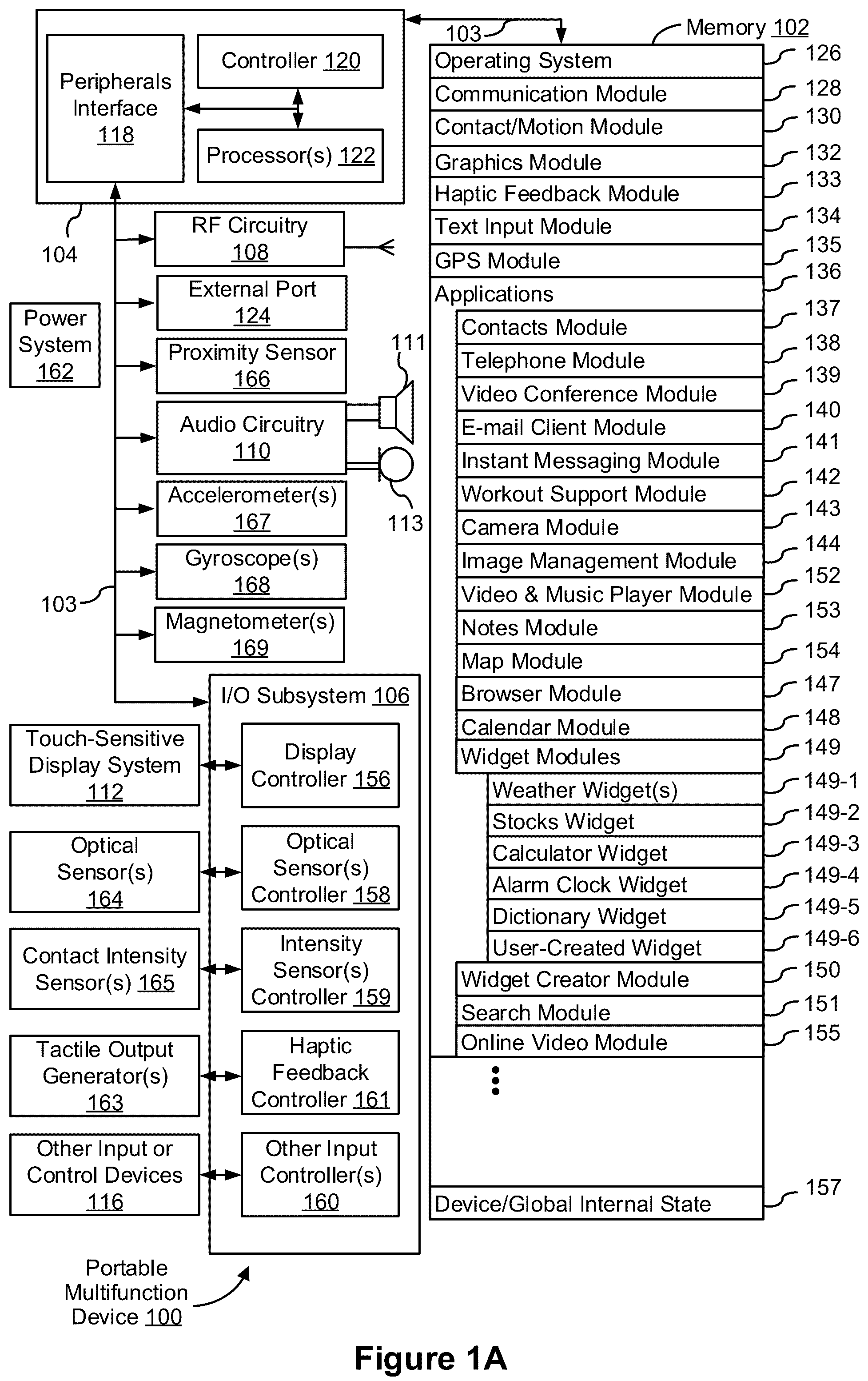
Attention is now directed toward embodiments of portable devices with touch-sensitive displays. A is a block diagram illustrating portable multifunction device 100 with touch-sensitive display system 112 in accordance with some embodiments. Touch-sensitive display system 112 is sometimes called a “touch screen” for convenience, and is sometimes simply called a touch-sensitive display. Device 100 includes memory 102 (which optionally includes one or more computer readable storage mediums), memory controller 120 , one or more processing units (CPUs) 122 , peripherals interface 118 , RF circuitry 108 , audio circuitry 110 , speaker 111 , microphone 113 , input/output (I/O) subsystem 106 , other input or control devices 116 , and external port 124 . Device 100 optionally includes one or more optical sensors 164 . Device 100 optionally includes one or more contact intensity sensors 165 for detecting intensity of contacts on device 100 (e.g., a touch-sensitive surface such as touch-sensitive display system 112 of device 100 ). Device 100 optionally includes one or more tactile output generators 163 for generating tactile outputs on device 100 (e.g., generating tactile outputs on a touch-sensitive surface such as touch-sensitive display system 112 of device 100 or touchpad 355 of device 300 ). These components optionally communicate over one or more communication buses or signal lines 103 .
As used in the specification and claims, the term “tactile output” refers to physical displacement of a device relative to a previous position of the device, physical displacement of a component (e.g., a touch-sensitive surface) of a device relative to another component (e.g., housing) of the device, or displacement of the component relative to a center of mass of the device that will be detected by a user with the user's sense of touch. For example, in situations where the device or the component of the device is in contact with a surface of a user that is sensitive to touch (e.g., a finger, palm, or other part of a user's hand), the tactile output generated by the physical displacement will be interpreted by the user as a tactile sensation corresponding to a perceived change in physical characteristics of the device or the component of the device. For example, movement of a touch-sensitive surface (e.g., a touch-sensitive display or trackpad) is, optionally, interpreted by the user as a “down click” or “up click” of a physical actuator button. In some cases, a user will feel a tactile sensation such as a “down click” or an “up click” even when there is no movement of a physical actuator button associated with the touch-sensitive surface that is physically pressed (e.g., displaced) by the user's movements. As another example, movement of the touch-sensitive surface is, optionally, interpreted or sensed by the user as “roughness” of the touch-sensitive surface, even when there is no change in smoothness of the touch-sensitive surface. While such interpretations of touch by a user will be subject to the individualized sensory perceptions of the user, there are many sensory perceptions of touch that are common to a large majority of users. Thus, when a tactile output is described as corresponding to a particular sensory perception of a user (e.g., an “up click,” a “down click,” “roughness”), unless otherwise stated, the generated tactile output corresponds to physical displacement of the device or a component thereof that will generate the described sensory perception for a typical (or average) user.
It should be appreciated that device 100 is only one example of a portable multifunction device, and that device 100 optionally has more or fewer components than shown, optionally combines two or more components, or optionally has a different configuration or arrangement of the components. The various components shown in A are implemented in hardware, software, firmware, or a combination thereof, including one or more signal processing and/or application specific integrated circuits.
Memory 102 optionally includes high-speed random access memory and optionally also includes non-volatile memory, such as one or more magnetic disk storage devices, flash memory devices, or other non-volatile solid-state memory devices. Access to memory 102 by other components of device 100 , such as CPU(s) 122 and the peripherals interface 118 , is, optionally, controlled by memory controller 120 .
Peripherals interface 118 can be used to couple input and output peripherals of the device to CPU(s) 122 and memory 102 . The one or more processors 122 run or execute various software programs and/or sets of instructions stored in memory 102 to perform various functions for device 100 and to process data.
In some embodiments, peripherals interface 118 , CPU(s) 122 , and memory controller 120 are, optionally, implemented on a single chip, such as chip 104 . In some other embodiments, they are, optionally, implemented on separate chips.
RF (radio frequency) circuitry 108 receives and sends RF signals, also called electromagnetic signals. RF circuitry 108 converts electrical signals to/from electromagnetic signals and communicates with communications networks and other communications devices via the electromagnetic signals. RF circuitry 108 optionally includes well-known circuitry for performing these functions, including but not limited to an antenna system, an RF transceiver, one or more amplifiers, a tuner, one or more oscillators, a digital signal processor, a CODEC chipset, a subscriber identity module (SIM) card, memory, and so forth. RF circuitry 108 optionally communicates with networks, such as the Internet, also referred to as the World Wide Web (WWW), an intranet and/or a wireless network, such as a cellular telephone network, a wireless local area network (LAN) and/or a metropolitan area network (MAN), and other devices by wireless communication. The wireless communication optionally uses any of a plurality of communications standards, protocols and technologies, including but not limited to Global System for Mobile Communications (GSM), Enhanced Data GSM Environment (EDGE), high-speed downlink packet access (HSDPA), high-speed uplink packet access (HSDPA), Evolution, Data-Only (EV-DO), HSPA, HSPA+, Dual-Cell HSPA (DC-HSPDA), long term evolution (LTE), near field communication (NFC), wideband code division multiple access (W-CDMA), code division multiple access (CDMA), time division multiple access (TDMA), Bluetooth, Wireless Fidelity (Wi-Fi) (e.g., IEEE 802.11a, IEEE 802.11ac, IEEE 802.11ax, IEEE 802.11b, IEEE 802.11g and/or IEEE 802.11n), voice over Internet Protocol (VoIP), Wi-MAX, a protocol for e-mail (e.g., Internet message access protocol (IMAP) and/or post office protocol (POP)), instant messaging (e.g., extensible messaging and presence protocol (XMPP), Session Initiation Protocol for Instant Messaging and Presence Leveraging Extensions (SIMPLE), Instant Messaging and Presence Service (IMPS)), and/or Short Message Service (SMS), or any other suitable communication protocol, including communication protocols not yet developed as of the filing date of this document.
Audio circuitry 110 , speaker 111 , and microphone 113 provide an audio interface between a user and device 100 . Audio circuitry 110 receives audio data from peripherals interface 118 , converts the audio data to an electrical signal, and transmits the electrical signal to speaker 111 . Speaker 111 converts the electrical signal to human-audible sound waves. Audio circuitry 110 also receives electrical signals converted by microphone 113 from sound waves. Audio circuitry 110 converts the electrical signal to audio data and transmits the audio data to peripherals interface 118 for processing. Audio data is, optionally, retrieved from and/or transmitted to memory 102 and/or RF circuitry 108 by peripherals interface 118 . In some embodiments, audio circuitry 110 also includes a headset jack (e.g., 212 , ). The headset jack provides an interface between audio circuitry 110 and removable audio input/output peripherals, such as output-only headphones or a headset with both output (e.g., a headphone for one or both ears) and input (e.g., a microphone).
I/O subsystem 106 couples input/output peripherals on device 100 , such as touch-sensitive display system 112 and other input or control devices 116 , with peripherals interface 118 . I/O subsystem 106 optionally includes display controller 156 , optical sensor controller 158 , intensity sensor controller 159 , haptic feedback controller 161 , and one or more input controllers 160 for other input or control devices. The one or more input controllers 160 receive/send electrical signals from/to other input or control devices 116 . The other input or control devices 116 optionally include physical buttons (e.g., push buttons, rocker buttons, etc.), dials, slider switches, joysticks, click wheels, and so forth. In some alternate embodiments, input controller(s) 160 are, optionally, coupled with any (or none) of the following: a keyboard, infrared port, USB port, stylus, and/or a pointer device such as a mouse. The one or more buttons (e.g., 208 , ) optionally include an up/down button for volume control of speaker 111 and/or microphone 113 . The one or more buttons optionally include a push button (e.g., 206 , ).
Touch-sensitive display system 112 provides an input interface and an output interface between the device and a user. Display controller 156 receives and/or sends electrical signals from/to touch-sensitive display system 112 . Touch-sensitive display system 112 displays visual output to the user. The visual output optionally includes graphics, text, icons, video, and any combination thereof (collectively termed “graphics”). In some embodiments, some or all of the visual output corresponds to user-interface objects.
Touch-sensitive display system 112 has a touch-sensitive surface, sensor or set of sensors that accepts input from the user based on haptic/tactile contact. Touch-sensitive display system 112 and display controller 156 (along with any associated modules and/or sets of instructions in memory 102 ) detect contact (and any movement or breaking of the contact) on touch-sensitive display system 112 and converts the detected contact into interaction with user-interface objects (e.g., one or more soft keys, icons, web pages or images) that are displayed on touch-sensitive display system 112 . In an example embodiment, a point of contact between touch-sensitive display system 112 and the user corresponds to a finger of the user or a stylus.
Touch-sensitive display system 112 optionally uses LCD (liquid crystal display) technology, LPD (light emitting polymer display) technology, or LED (light emitting diode) technology, although other display technologies are used in other embodiments. Touch-sensitive display system 112 and display controller 156 optionally detect contact and any movement or breaking thereof using any of a plurality of touch sensing technologies now known or later developed, including but not limited to capacitive, resistive, infrared, and surface acoustic wave technologies, as well as other proximity sensor arrays or other elements for determining one or more points of contact with touch-sensitive display system 112 . In an example embodiment, projected mutual capacitance sensing technology is used, such as that found in the iPhone®, iPod Touch®, and iPad® from Apple Inc. of Cupertino, California.
Touch-sensitive display system 112 optionally has a video resolution in excess of 100 dpi. In some embodiments, the touch screen video resolution is in excess of 400 dpi (e.g., 500 dpi, 800 dpi, or greater). The user optionally makes contact with touch-sensitive display system 112 using any suitable object or appendage, such as a stylus, a finger, and so forth. In some embodiments, the user interface is designed to work with finger-based contacts and gestures, which can be less precise than stylus-based input due to the larger area of contact of a finger on the touch screen. In some embodiments, the device translates the rough finger-based input into a precise pointer/cursor position or command for performing the actions desired by the user.
In some embodiments, in addition to the touch screen, device 100 optionally includes a touchpad (not shown) for activating or deactivating particular functions. In some embodiments, the touchpad is a touch-sensitive area of the device that, unlike the touch screen, does not display visual output. The touchpad is, optionally, a touch-sensitive surface that is separate from touch-sensitive display system 112 or an extension of the touch-sensitive surface formed by the touch screen.
Device 100 also includes power system 162 for powering the various components. Power system 162 optionally includes a power management system, one or more power sources (e.g., battery, alternating current (AC)), a recharging system, a power failure detection circuit, a power converter or inverter, a power status indicator (e.g., a light-emitting diode (LED)) and any other components associated with the generation, management and distribution of power in portable devices.
Device 100 optionally also includes one or more optical sensors 164 . A shows an optical sensor coupled with optical sensor controller 158 in I/O subsystem 106 . Optical sensor(s) 164 optionally include charge-coupled device (CCD) or complementary metal-oxide semiconductor (CMOS) phototransistors. Optical sensor(s) 164 receive light from the environment, projected through one or more lens, and converts the light to data representing an image. In conjunction with camera module 143 (also called an imaging module), optical sensor(s) 164 optionally capture still images and/or video. In some embodiments, an optical sensor is located on the back of device 100 , opposite touch-sensitive display system 112 on the front of the device, so that the touch screen is enabled for use as a viewfinder for still and/or video image acquisition. In some embodiments, another optical sensor is located on the front of the device so that the user's image is obtained (e.g., for selfies, for videoconferencing while the user views the other video conference participants on the touch screen, etc.).
Device 100 optionally also includes one or more contact intensity sensors 165 . A shows a contact intensity sensor coupled with intensity sensor controller 159 in I/O subsystem 106 . Contact intensity sensor(s) 165 optionally include one or more piezoresistive strain gauges, capacitive force sensors, electric force sensors, piezoelectric force sensors, optical force sensors, capacitive touch-sensitive surfaces, or other intensity sensors (e.g., sensors used to measure the force (or pressure) of a contact on a touch-sensitive surface). Contact intensity sensor(s) 165 receive contact intensity information (e.g., pressure information or a proxy for pressure information) from the environment. In some embodiments, at least one contact intensity sensor is collocated with, or proximate to, a touch-sensitive surface (e.g., touch-sensitive display system 112 ). In some embodiments, at least one contact intensity sensor is located on the back of device 100 , opposite touch-screen display system 112 which is located on the front of device 100 .
Device 100 optionally also includes one or more proximity sensors 166 . A shows proximity sensor 166 coupled with peripherals interface 118 . Alternately, proximity sensor 166 is coupled with input controller 160 in I/O subsystem 106 . In some embodiments, the proximity sensor turns off and disables touch-sensitive display system 112 when the multifunction device is placed near the user's ear (e.g., when the user is making a phone call).
Device 100 optionally also includes one or more tactile output generators 163 . A shows a tactile output generator coupled with haptic feedback controller 161 in I/O subsystem 106 . Tactile output generator(s) 163 optionally include one or more electroacoustic devices such as speakers or other audio components and/or electromechanical devices that convert energy into linear motion such as a motor, solenoid, electroactive polymer, piezoelectric actuator, electrostatic actuator, or other tactile output generating component (e.g., a component that converts electrical signals into tactile outputs on the device). Tactile output generator(s) 163 receive tactile feedback generation instructions from haptic feedback module 133 and generates tactile outputs on device 100 that are capable of being sensed by a user of device 100 . In some embodiments, at least one tactile output generator is collocated with, or proximate to, a touch-sensitive surface (e.g., touch-sensitive display system 112 ) and, optionally, generates a tactile output by moving the touch-sensitive surface vertically (e.g., in/out of a surface of device 100 ) or laterally (e.g., back and forth in the same plane as a surface of device 100 ). In some embodiments, at least one tactile output generator sensor is located on the back of device 100 , opposite touch-sensitive display system 112 , which is located on the front of device 100 .
Device 100 optionally also includes one or more accelerometers 167 , gyroscopes 168 , and/or magnetometers 169 (e.g., as part of an inertial measurement unit (IMU)) for obtaining information concerning the position (e.g., attitude) of the device. A shows sensors 167 , 168 , and 169 coupled with peripherals interface 118 . Alternately, sensors 167 , 168 , and 169 are, optionally, coupled with an input controller 160 in I/O subsystem 106 . In some embodiments, information is displayed on the touch-screen display in a portrait view or a landscape view based on an analysis of data received from the one or more accelerometers. Device 100 optionally includes a GPS (or GLONASS or other global navigation system) receiver (not shown) for obtaining information concerning the location of device 100 .
In some embodiments, the software components stored in memory 102 include operating system 126 , communication module (or set of instructions) 128 , contact/motion module (or set of instructions) 130 , graphics module (or set of instructions) 132 , haptic feedback module (or set of instructions) 133 , text input module (or set of instructions) 134 , Global Positioning System (GPS) module (or set of instructions) 135 , and applications (or sets of instructions) 136 . Furthermore, in some embodiments, memory 102 stores device/global internal state 157 , as shown in A and 3 . Device/global internal state 157 includes one or more of: active application state, indicating which applications, if any, are currently active; display state, indicating what applications, views or other information occupy various regions of touch-sensitive display system 112 ; sensor state, including information obtained from the device's various sensors and other input or control devices 116 ; and location and/or positional information concerning the device's location and/or attitude.
Operating system 126 (e.g., iOS, Darwin, RTXC, LINUX, UNIX, OS X, WINDOWS, or an embedded operating system such as VxWorks) includes various software components and/or drivers for controlling and managing general system tasks (e.g., memory management, storage device control, power management, etc.) and facilitates communication between various hardware and software components.
Communication module 128 facilitates communication with other devices over one or more external ports 124 and also includes various software components for handling data received by RF circuitry 108 and/or external port 124 . External port 124 (e.g., Universal Serial Bus (USB), FIREWIRE, etc.) is adapted for coupling directly to other devices or indirectly over a network (e.g., the Internet, wireless LAN, etc.). In some embodiments, the external port is a multi-pin (e.g., 30-pin) connector that is the same as, or similar to and/or compatible with the 30-pin connector used in some iPhone®, iPod Touch®, and iPad® devices from Apple Inc. of Cupertino, California. In some embodiments, the external port is a Lightning connector that is the same as, or similar to and/or compatible with the Lightning connector used in some iPhone®, iPod Touch®, and iPad® devices from Apple Inc. of Cupertino, California.
Contact/motion module 130 optionally detects contact with touch-sensitive display system 112 (in conjunction with display controller 156 ) and other touch-sensitive devices (e.g., a touchpad or physical click wheel). Contact/motion module 130 includes software components for performing various operations related to detection of contact (e.g., by a finger or by a stylus), such as determining if contact has occurred (e.g., detecting a finger-down event), determining an intensity of the contact (e.g., the force or pressure of the contact or a substitute for the force or pressure of the contact), determining if there is movement of the contact and tracking the movement across the touch-sensitive surface (e.g., detecting one or more finger-dragging events), and determining if the contact has ceased (e.g., detecting a finger-up event or a break in contact). Contact/motion module 130 receives contact data from the touch-sensitive surface. Determining movement of the point of contact, which is represented by a series of contact data, optionally includes determining speed (magnitude), velocity (magnitude and direction), and/or an acceleration (a change in magnitude and/or direction) of the point of contact. These operations are, optionally, applied to single contacts (e.g., one finger contacts or stylus contacts) or to multiple simultaneous contacts (e.g., “multitouch”/multiple finger contacts and/or stylus contacts). In some embodiments, contact/motion module 130 and display controller 156 detect contact on a touchpad.
Contact/motion module 130 optionally detects a gesture input by a user. Different gestures on the touch-sensitive surface have different contact patterns (e.g., different motions, timings, and/or intensities of detected contacts). Thus, a gesture is, optionally, detected by detecting a particular contact pattern. For example, detecting a finger tap gesture includes detecting a finger-down event followed by detecting a finger-up (lift off) event at the same position (or substantially the same position) as the finger-down event (e.g., at the position of an icon). As another example, detecting a finger swipe gesture on the touch-sensitive surface includes detecting a finger-down event followed by detecting one or more finger-dragging events, and subsequently followed by detecting a finger-up (lift off) event. Similarly, tap, swipe, drag, and other gestures are optionally detected for a stylus by detecting a particular contact pattern for the stylus.
Graphics module 132 includes various known software components for rendering and displaying graphics on touch-sensitive display system 112 or other display, including components for changing the visual impact (e.g., brightness, transparency, saturation, contrast or other visual property) of graphics that are displayed. As used herein, the term “graphics” includes any object that can be displayed to a user, including without limitation text, web pages, icons (such as user-interface objects including soft keys), digital images, videos, animations and the like.
In some embodiments, graphics module 132 stores data representing graphics to be used. Each graphic is, optionally, assigned a corresponding code. Graphics module 132 receives, from applications etc., one or more codes specifying graphics to be displayed along with, if necessary, coordinate data and other graphic property data, and then generates screen image data to output to display controller 156 .
Haptic feedback module 133 includes various software components for generating instructions used by tactile output generator(s) 163 to produce tactile outputs at one or more locations on device 100 in response to user interactions with device 100 .
Text input module 134 , which is, optionally, a component of graphics module 132 , provides soft keyboards for entering text in various applications (e.g., contacts 137 , e-mail client 140 , IM 141 , browser 147 , and any other application that needs text input).
GPS module 135 determines the location of the device and provides this information for use in various applications (e.g., to telephone module 138 for use in location-based dialing, to camera module 143 as picture/video metadata, and to applications that provide location-based services such as weather widgets, local yellow page widgets, and map/navigation widgets).
Applications 136 optionally include the following modules (or sets of instructions), or a subset or superset thereof:
•
• contacts module 137 (sometimes called an address book or contact list); • telephone module 138 ; • video conference module 139 ; • e-mail client module 140 ; • instant messaging (IM) module 141 ; • workout support module 142 ; • camera module 143 for still and/or video images; • image management module 144 ; • browser module 147 ; • calendar module 148 ; • widget modules 149 , which optionally include one or more of: weather widget 149 - 1 , stocks widget 149 - 2 , calculator widget 149 - 3 , alarm clock widget 149 - 4 , dictionary widget 149 - 5 , and other widgets obtained by the user, as well as user-created widgets 149 - 6 ; • widget creator module 150 for making user-created widgets 149 - 6 ; • search module 151 ; • video and music player module 152 , which is, optionally, made up of a video player module and a music player module; • notes module 153 ; • map module 154 ; and/or • online video module 155 .
Examples of other applications 136 that are, optionally, stored in memory 102 include other word processing applications, other image editing applications, drawing applications, presentation applications, JAVA-enabled applications, encryption, digital rights management, voice recognition, and voice replication.
In conjunction with touch-sensitive display system 112 , display controller 156 , contact module 130 , graphics module 132 , and text input module 134 , contacts module 137 includes executable instructions to manage an address book or contact list (e.g., stored in application internal state 192 of contacts module 137 in memory 102 or memory 370 ), including: adding name(s) to the address book; deleting name(s) from the address book; associating telephone number(s), e-mail address(es), physical address(es) or other information with a name; associating an image with a name; categorizing and sorting names; providing telephone numbers and/or e-mail addresses to initiate and/or facilitate communications by telephone module 138 , video conference 139 , e-mail client 140 , or IM 141 ; and so forth.
In conjunction with RF circuitry 108 , audio circuitry 110 , speaker 111 , microphone 113 , touch-sensitive display system 112 , display controller 156 , contact module 130 , graphics module 132 , and text input module 134 , telephone module 138 includes executable instructions to enter a sequence of characters corresponding to a telephone number, access one or more telephone numbers in address book 137 , modify a telephone number that has been entered, dial a respective telephone number, conduct a conversation and disconnect or hang up when the conversation is completed. As noted above, the wireless communication optionally uses any of a plurality of communications standards, protocols and technologies.
In conjunction with RF circuitry 108 , audio circuitry 110 , speaker 111 , microphone 113 , touch-sensitive display system 112 , display controller 156 , optical sensor(s) 164 , optical sensor controller 158 , contact module 130 , graphics module 132 , text input module 134 , contact list 137 , and telephone module 138 , video conference module 139 includes executable instructions to initiate, conduct, and terminate a video conference between a user and one or more other participants in accordance with user instructions.
In conjunction with RF circuitry 108 , touch-sensitive display system 112 , display controller 156 , contact module 130 , graphics module 132 , and text input module 134 , e-mail client module 140 includes executable instructions to create, send, receive, and manage e-mail in response to user instructions. In conjunction with image management module 144 , e-mail client module 140 makes it very easy to create and send e-mails with still or video images taken with camera module 143 .
In conjunction with RF circuitry 108 , touch-sensitive display system 112 , display controller 156 , contact module 130 , graphics module 132 , and text input module 134 , the instant messaging module 141 includes executable instructions to enter a sequence of characters corresponding to an instant message, to modify previously entered characters, to transmit a respective instant message (for example, using a Short Message Service (SMS) or Multimedia Message Service (MMS) protocol for telephony-based instant messages or using XMPP, SIMPLE, Apple Push Notification Service (APNs) or IMPS for Internet-based instant messages), to receive instant messages and to view received instant messages. In some embodiments, transmitted and/or received instant messages optionally include graphics, photos, audio files, video files and/or other attachments as are supported in a MMS and/or an Enhanced Messaging Service (EMS). As used herein, “instant messaging” refers to both telephony-based messages (e.g., messages sent using SMS or MMS) and Internet-based messages (e.g., messages sent using XMPP, SIMPLE, APNs, or IMPS).
In conjunction with RF circuitry 108 , touch-sensitive display system 112 , display controller 156 , contact module 130 , graphics module 132 , text input module 134 , GPS module 135 , map module 154 , and video and music player module 152 , workout support module 142 includes executable instructions to create workouts (e.g., with time, distance, and/or calorie burning goals); communicate with workout sensors (in sports devices and smart watches); receive workout sensor data; calibrate sensors used to monitor a workout; select and play music for a workout; and display, store and transmit workout data.
In conjunction with touch-sensitive display system 112 , display controller 156 , optical sensor(s) 164 , optical sensor controller 158 , contact module 130 , graphics module 132 , and image management module 144 , camera module 143 includes executable instructions to capture still images or video (including a video stream) and store them into memory 102 , modify characteristics of a still image or video, and/or delete a still image or video from memory 102 .
In conjunction with touch-sensitive display system 112 , display controller 156 , contact module 130 , graphics module 132 , text input module 134 , and camera module 143 , image management module 144 includes executable instructions to arrange, modify (e.g., edit), or otherwise manipulate, label, delete, present (e.g., in a digital slide show or album), and store still and/or video images.
In conjunction with RF circuitry 108 , touch-sensitive display system 112 , display system controller 156 , contact module 130 , graphics module 132 , and text input module 134 , browser module 147 includes executable instructions to browse the Internet in accordance with user instructions, including searching, linking to, receiving, and displaying web pages or portions thereof, as well as attachments and other files linked to web pages.
In conjunction with RF circuitry 108 , touch-sensitive display system 112 , display system controller 156 , contact module 130 , graphics module 132 , text input module 134 , e-mail client module 140 , and browser module 147 , calendar module 148 includes executable instructions to create, display, modify, and store calendars and data associated with calendars (e.g., calendar entries, to do lists, etc.) in accordance with user instructions.
In conjunction with RF circuitry 108 , touch-sensitive display system 112 , display system controller 156 , contact module 130 , graphics module 132 , text input module 134 , and browser module 147 , widget modules 149 are mini-applications that are, optionally, downloaded and used by a user (e.g., weather widget 149 - 1 , stocks widget 149 - 2 , calculator widget 149 - 3 , alarm clock widget 149 - 4 , and dictionary widget 149 - 5 ) or created by the user (e.g., user-created widget 149 - 6 ). In some embodiments, a widget includes an HTML (Hypertext Markup Language) file, a CSS (Cascading Style Sheets) file, and a JavaScript file. In some embodiments, a widget includes an XML (Extensible Markup Language) file and a JavaScript file (e.g., Yahoo! Widgets).
In conjunction with RF circuitry 108 , touch-sensitive display system 112 , display system controller 156 , contact module 130 , graphics module 132 , text input module 134 , and browser module 147 , the widget creator module 150 includes executable instructions to create widgets (e.g., turning a user-specified portion of a web page into a widget).
In conjunction with touch-sensitive display system 112 , display system controller 156 , contact module 130 , graphics module 132 , and text input module 134 , search module 151 includes executable instructions to search for text, music, sound, image, video, and/or other files in memory 102 that match one or more search criteria (e.g., one or more user-specified search terms) in accordance with user instructions.
In conjunction with touch-sensitive display system 112 , display system controller 156 , contact module 130 , graphics module 132 , audio circuitry 110 , speaker 111 , RF circuitry 108 , and browser module 147 , video and music player module 152 includes executable instructions that allow the user to download and play back recorded music and other sound files stored in one or more file formats, such as MP3 or AAC files, and executable instructions to display, present or otherwise play back videos (e.g., on touch-sensitive display system 112 , or on an external display connected wirelessly or via external port 124 ). In some embodiments, device 100 optionally includes the functionality of an MP3 player, such as an iPod (trademark of Apple Inc.).
In conjunction with touch-sensitive display system 112 , display controller 156 , contact module 130 , graphics module 132 , and text input module 134 , notes module 153 includes executable instructions to create and manage notes, to do lists, and the like in accordance with user instructions.
In conjunction with RF circuitry 108 , touch-sensitive display system 112 , display system controller 156 , contact module 130 , graphics module 132 , text input module 134 , GPS module 135 , and browser module 147 , map module 154 includes executable instructions to receive, display, modify, and store maps and data associated with maps (e.g., driving directions; data on stores and other points of interest at or near a particular location; and other location-based data) in accordance with user instructions.
In conjunction with touch-sensitive display system 112 , display system controller 156 , contact module 130 , graphics module 132 , audio circuitry 110 , speaker 111 , RF circuitry 108 , text input module 134 , e-mail client module 140 , and browser module 147 , online video module 155 includes executable instructions that allow the user to access, browse, receive (e.g., by streaming and/or download), play back (e.g., on the touch screen 112 , or on an external display connected wirelessly or via external port 124 ), send an e-mail with a link to a particular online video, and otherwise manage online videos in one or more file formats, such as H.264. In some embodiments, instant messaging module 141 , rather than e-mail client module 140 , is used to send a link to a particular online video.
Each of the above identified modules and applications correspond to a set of executable instructions for performing one or more functions described above and the methods described in this application (e.g., the computer-implemented methods and other information processing methods described herein). These modules (i.e., sets of instructions) need not be implemented as separate software programs, procedures or modules, and thus various subsets of these modules are, optionally, combined or otherwise re-arranged in various embodiments. In some embodiments, memory 102 optionally stores a subset of the modules and data structures identified above. Furthermore, memory 102 optionally stores additional modules and data structures not described above.
In some embodiments, device 100 is a device where operation of a predefined set of functions on the device is performed exclusively through a touch screen and/or a touchpad. By using a touch screen and/or a touchpad as the primary input control device for operation of device 100 , the number of physical input control devices (such as push buttons, dials, and the like) on device 100 is, optionally, reduced.
The predefined set of functions that are performed exclusively through a touch screen and/or a touchpad optionally include navigation between user interfaces. In some embodiments, the touchpad, when touched by the user, navigates device 100 to a main, home, or root menu from any user interface that is displayed on device 100 . In such embodiments, a “menu button” is implemented using a touchpad. In some other embodiments, the menu button is a physical push button or other physical input control device instead of a touchpad.
B is a block diagram illustrating example components for event handling in accordance with some embodiments. In some embodiments, memory 102 (in A ) or 370 ( ) includes event sorter 170 (e.g., in operating system 126 ) and a respective application 136 - 1 (e.g., any of the aforementioned applications 136 , 137 - 155 , 380 - 390 ).
Event sorter 170 receives event information and determines the application 136 - 1 and application view 191 of application 136 - 1 to which to deliver the event information. Event sorter 170 includes event monitor 171 and event dispatcher module 174 . In some embodiments, application 136 - 1 includes application internal state 192 , which indicates the current application view(s) displayed on touch-sensitive display system 112 when the application is active or executing. In some embodiments, device/global internal state 157 is used by event sorter 170 to determine which application(s) is (are) currently active, and application internal state 192 is used by event sorter 170 to determine application views 191 to which to deliver event information.
In some embodiments, application internal state 192 includes additional information, such as one or more of: resume information to be used when application 136 - 1 resumes execution, user interface state information that indicates information being displayed or that is ready for display by application 136 - 1 , a state queue for enabling the user to go back to a prior state or view of application 136 - 1 , and a redo/undo queue of previous actions taken by the user.
Event monitor 171 receives event information from peripherals interface 118 . Event information includes information about a sub-event (e.g., a user touch on touch-sensitive display system 112 , as part of a multi-touch gesture). Peripherals interface 118 transmits information it receives from I/O subsystem 106 or a sensor, such as proximity sensor 166 , accelerometer(s) 167 , gyroscope(s) 168 , magnetometer(s) 169 , and/or microphone 113 (through audio circuitry 110 ). Information that peripherals interface 118 receives from I/O subsystem 106 includes information from touch-sensitive display system 112 or a touch-sensitive surface.
In some embodiments, event monitor 171 sends requests to the peripherals interface 118 at predetermined intervals. In response, peripherals interface 118 transmits event information. In other embodiments, peripheral interface 118 transmits event information only when there is a significant event (e.g., receiving an input above a predetermined noise threshold and/or for more than a predetermined duration).
In some embodiments, event sorter 170 also includes a hit view determination module 172 and/or an active event recognizer determination module 173 .
Hit view determination module 172 provides software procedures for determining where a sub-event has taken place within one or more views, when touch-sensitive display system 112 displays more than one view. Views are made up of controls and other elements that a user can see on the display.
Another aspect of the user interface associated with an application is a set of views, sometimes herein called application views or user interface windows, in which information is displayed and touch-based gestures occur. The application views (of a respective application) in which a touch is detected optionally correspond to programmatic levels within a programmatic or view hierarchy of the application. For example, the lowest level view in which a touch is detected is, optionally, called the hit view, and the set of events that are recognized as proper inputs are, optionally, determined based, at least in part, on the hit view of the initial touch that begins a touch-based gesture.
Hit view determination module 172 receives information related to sub-events of a touch-based gesture. When an application has multiple views organized in a hierarchy, hit view determination module 172 identifies a hit view as the lowest view in the hierarchy which should handle the sub-event. In most circumstances, the hit view is the lowest level view in which an initiating sub-event occurs (i.e., the first sub-event in the sequence of sub-events that form an event or potential event). Once the hit view is identified by the hit view determination module, the hit view typically receives all sub-events related to the same touch or input source for which it was identified as the hit view.
Active event recognizer determination module 173 determines which view or views within a view hierarchy should receive a particular sequence of sub-events. In some embodiments, active event recognizer determination module 173 determines that only the hit view should receive a particular sequence of sub-events. In other embodiments, active event recognizer determination module 173 determines that all views that include the physical location of a sub-event are actively involved views, and therefore determines that all actively involved views should receive a particular sequence of sub-events. In other embodiments, even if touch sub-events were entirely confined to the area associated with one particular view, views higher in the hierarchy would still remain as actively involved views.
Event dispatcher module 174 dispatches the event information to an event recognizer (e.g., event recognizer 180 ). In embodiments including active event recognizer determination module 173 , event dispatcher module 174 delivers the event information to an event recognizer determined by active event recognizer determination module 173 . In some embodiments, event dispatcher module 174 stores in an event queue the event information, which is retrieved by a respective event receiver module 182 .
In some embodiments, operating system 126 includes event sorter 170 . Alternatively, application 136 - 1 includes event sorter 170 . In yet other embodiments, event sorter 170 is a stand-alone module, or a part of another module stored in memory 102 , such as contact/motion module 130 .
In some embodiments, application 136 - 1 includes a plurality of event handlers 190 and one or more application views 191 , each of which includes instructions for handling touch events that occur within a respective view of the application's user interface. Each application view 191 of the application 136 - 1 includes one or more event recognizers 180 . Typically, a respective application view 191 includes a plurality of event recognizers 180 . In other embodiments, one or more of event recognizers 180 are part of a separate module, such as a user interface kit (not shown) or a higher level object from which application 136 - 1 inherits methods and other properties. In some embodiments, a respective event handler 190 includes one or more of: data updater 176 , object updater 177 , GUI updater 178 , and/or event data 179 received from event sorter 170 . Event handler 190 optionally utilizes or calls data updater 176 , object updater 177 or GUI updater 178 to update the application internal state 192 . Alternatively, one or more of the application views 191 includes one or more respective event handlers 190 . Also, in some embodiments, one or more of data updater 176 , object updater 177 , and GUI updater 178 are included in a respective application view 191 .
A respective event recognizer 180 receives event information (e.g., event data 179 ) from event sorter 170 , and identifies an event from the event information. Event recognizer 180 includes event receiver 182 and event comparator 184 . In some embodiments, event recognizer 180 also includes at least a subset of: metadata 183 , and event delivery instructions 188 (which optionally include sub-event delivery instructions).
Event receiver 182 receives event information from event sorter 170 . The event information includes information about a sub-event, for example, a touch or a touch movement. Depending on the sub-event, the event information also includes additional information, such as location of the sub-event. When the sub-event concerns motion of a touch, the event information optionally also includes speed and direction of the sub-event. In some embodiments, events include rotation of the device from one orientation to another (e.g., from a portrait orientation to a landscape orientation, or vice versa), and the event information includes corresponding information about the current orientation (also called device attitude) of the device.
Event comparator 184 compares the event information to predefined event or sub-event definitions and, based on the comparison, determines an event or sub-event, or determines or updates the state of an event or sub-event. In some embodiments, event comparator 184 includes event definitions 186 . Event definitions 186 contain definitions of events (e.g., predefined sequences of sub-events), for example, event 1 ( 187 - 1 ), event 2 ( 187 - 2 ), and others. In some embodiments, sub-events in a respective event, such as event 1 ( 187 - 1 ) or event 2 ( 187 - 2 ), include, for example, touch begin, touch end, touch movement, touch cancellation, and multiple touching. In one example, the definition for event 1 ( 187 - 1 ) is a double tap on a displayed object. The double tap, for example, comprises a first touch (touch begin) on the displayed object for a predetermined phase, a first lift-off (touch end) for a predetermined phase, a second touch (touch begin) on the displayed object for a predetermined phase, and a second lift-off (touch end) for a predetermined phase. In another example, the definition for event 2 ( 187 - 2 ) is a dragging on a displayed object. The dragging, for example, comprises a touch (or contact) on the displayed object for a predetermined phase, a movement of the touch across touch-sensitive display system 112 , and lift-off of the touch (touch end). In some embodiments, the event also includes information for one or more associated event handlers 190 .
In some embodiments, the event definition for a respective event, such as event 1 ( 187 - 1 ) or event 2 ( 187 - 2 ), includes a definition of an event for a respective user-interface object. In some embodiments, event comparator 184 performs a hit test to determine which user-interface object is associated with a sub-event. For example, in an application view in which three user-interface objects are displayed on touch-sensitive display system 112 , when a touch is detected on touch-sensitive display system 112 , event comparator 184 performs a hit test to determine which of the three user-interface objects is associated with the touch (sub-event). If each displayed object is associated with a respective event handler 190 , the event comparator uses the result of the hit test to determine which event handler 190 should be activated. For example, event comparator 184 selects an event handler associated with the sub-event and the object triggering the hit test.
In some embodiments, the definition for a respective event, such as event 1 ( 187 - 1 ) or event 2 ( 187 - 2 ), also includes delayed actions that delay delivery of the event information until after it has been determined whether the sequence of sub-events does or does not correspond to the event recognizer's event type.
When a respective event recognizer 180 determines that the series of sub-events do not match any of the events in event definitions 186 , the respective event recognizer 180 enters an event impossible, event failed, or event ended state, after which it disregards subsequent sub-events of the touch-based gesture. In this situation, other event recognizers, if any, that remain active for the hit view continue to track and process sub-events of an ongoing touch-based gesture.
In some embodiments, a respective event recognizer 180 includes metadata 183 with configurable properties, flags, and/or lists that indicate how the event delivery system should perform sub-event delivery to actively involved event recognizers. In some embodiments, metadata 183 includes configurable properties, flags, and/or lists that indicate how event recognizers interact, or are enabled to interact, with one another. In some embodiments, metadata 183 includes configurable properties, flags, and/or lists that indicate whether sub-events are delivered to varying levels in the view or programmatic hierarchy.
In some embodiments, a respective event recognizer 180 activates event handler 190 associated with an event when one or more particular sub-events of an event are recognized. In some embodiments, a respective event recognizer 180 delivers event information associated with the event to event handler 190 . Activating an event handler 190 is distinct from sending (and deferred sending) sub-events to a respective hit view. In some embodiments, event recognizer 180 throws a flag associated with the recognized event, and event handler 190 associated with the flag catches the flag and performs a predefined process.
In some embodiments, event delivery instructions 188 include sub-event delivery instructions that deliver event information about a sub-event without activating an event handler. Instead, the sub-event delivery instructions deliver event information to event handlers associated with the series of sub-events or to actively involved views. Event handlers associated with the series of sub-events or with actively involved views receive the event information and perform a predetermined process.
In some embodiments, data updater 176 creates and updates data used in application 136 - 1 . For example, data updater 176 updates the telephone number used in contacts module 137 , or stores a video file used in video player module 145 . In some embodiments, object updater 177 creates and updates objects used in application 136 - 1 . For example, object updater 177 creates a new user-interface object or updates the position of a user-interface object. GUI updater 178 updates the GUI. For example, GUI updater 178 prepares display information and sends it to graphics module 132 for display on a touch-sensitive display.
In some embodiments, event handler(s) 190 includes or has access to data updater 176 , object updater 177 , and GUI updater 178 . In some embodiments, data updater 176 , object updater 177 , and GUI updater 178 are included in a single module of a respective application 136 - 1 or application view 191 . In other embodiments, they are included in two or more software modules.
It shall be understood that the foregoing discussion regarding event handling of user touches on touch-sensitive displays also applies to other forms of user inputs to operate multifunction devices 100 with input-devices, not all of which are initiated on touch screens. For example, mouse movement and mouse button presses, optionally coordinated with single or multiple keyboard presses or holds; contact movements such as taps, drags, scrolls, etc., on touch-pads; pen stylus inputs; movement of the device; oral instructions; detected eye movements; biometric inputs; and/or any combination thereof are optionally utilized as inputs corresponding to sub-events which define an event to be recognized.
illustrates a portable multifunction device 100 having a touch screen (e.g., touch-sensitive display system 112 , A ) in accordance with some embodiments. The touch screen optionally displays one or more graphics within user interface (UI) 200 . In this embodiment, as well as others described below, a user is enabled to select one or more of the graphics by making a gesture on the graphics, for example, with one or more fingers 202 (not drawn to scale in the figure) or one or more styluses 203 (not drawn to scale in the figure). In some embodiments, selection of one or more graphics occurs when the user breaks contact with the one or more graphics. In some embodiments, the gesture optionally includes one or more taps, one or more swipes (from left to right, right to left, upward and/or downward) and/or a rolling of a finger (from right to left, left to right, upward and/or downward) that has made contact with device 100 . In some implementations or circumstances, inadvertent contact with a graphic does not select the graphic. For example, a swipe gesture that sweeps over an application icon optionally does not select the corresponding application when the gesture corresponding to selection is a tap.
Device 100 optionally also includes one or more physical buttons, such as “home” or menu button 204 . As described previously, menu button 204 is, optionally, used to navigate to any application 136 in a set of applications that are, optionally executed on device 100 . Alternatively, in some embodiments, the menu button is implemented as a soft key in a GUI displayed on the touch-screen display.
In some embodiments, device 100 includes the touch-screen display, menu button 204 , push button 206 for powering the device on/off and locking the device, volume adjustment button(s) 208 , Subscriber Identity Module (SIM) card slot 210 , head set jack 212 , and docking/charging external port 124 . Push button 206 is, optionally, used to turn the power on/off on the device by depressing the button and holding the button in the depressed state for a predefined time interval; to lock the device by depressing the button and releasing the button before the predefined time interval has elapsed; and/or to unlock the device or initiate an unlock process. In some embodiments, device 100 also accepts verbal input for activation or deactivation of some functions through microphone 113 . Device 100 also, optionally, includes one or more contact intensity sensors 165 for detecting intensity of contacts on touch-sensitive display system 112 and/or one or more tactile output generators 163 for generating tactile outputs for a user of device 100 .
is a block diagram of an example multifunction device with a display and a touch-sensitive surface in accordance with some embodiments. Device 300 need not be portable. In some embodiments, device 300 is a laptop computer, a desktop computer, a tablet computer, a multimedia player device, a navigation device, an educational device (such as a child's learning toy), a gaming system, or a control device (e.g., a home or industrial controller). Device 300 typically includes one or more processing units (CPU's) 310 , one or more network or other communications interfaces 360 , memory 370 , and one or more communication buses 320 for interconnecting these components. Communication buses 320 optionally include circuitry (sometimes called a chipset) that interconnects and controls communications between system components. Device 300 includes input/output (I/O) interface 330 comprising display 340 , which is typically a touch-screen display. I/O interface 330 also optionally includes a keyboard and/or mouse (or other pointing device) 350 and touchpad 355 , tactile output generator 357 for generating tactile outputs on device 300 (e.g., similar to tactile output generator(s) 163 described above with reference to A ), sensors 359 (e.g., touch-sensitive, optical, contact intensity, proximity, acceleration, attitude, and/or magnetic sensors similar to sensors 112 , 164 , 165 , 166 , 167 , 168 , and 169 described above with reference to A ). Memory 370 includes high-speed random access memory, such as DRAM, SRAM, DDR RAM or other random access solid state memory devices; and optionally includes non-volatile memory, such as one or more magnetic disk storage devices, optical disk storage devices, flash memory devices, or other non-volatile solid state storage devices. Memory 370 optionally includes one or more storage devices remotely located from CPU(s) 310 . In some embodiments, memory 370 stores programs, modules, and data structures analogous to the programs, modules, and data structures stored in memory 102 of portable multifunction device 100 ( A ), or a subset thereof. Furthermore, memory 370 optionally stores additional programs, modules, and data structures not present in memory 102 of portable multifunction device 100 . For example, memory 370 of device 300 optionally stores drawing module 380 , presentation module 382 , word processing module 384 , website creation module 386 , disk authoring module 388 , and/or spreadsheet module 390 , while memory 102 of portable multifunction device 100 ( A ) optionally does not store these modules.
Each of the above identified elements in are, optionally, stored in one or more of the previously mentioned memory devices. Each of the above identified modules corresponds to a set of instructions for performing a function described above. The above identified modules or programs (i.e., sets of instructions) need not be implemented as separate software programs, procedures or modules, and thus various subsets of these modules are, optionally, combined or otherwise re-arranged in various embodiments. In some embodiments, memory 370 optionally stores a subset of the modules and data structures identified above. Furthermore, memory 370 optionally stores additional modules and data structures not described above.
Attention is now directed towards embodiments of user interfaces (“UI”) that are, optionally, implemented on portable multifunction device 100 .
A illustrates an example user interface for a menu of applications on portable multifunction device 100 in accordance with some embodiments. Similar user interfaces are, optionally, implemented on device 300 . In some embodiments, user interface 400 includes the following elements, or a subset or superset thereof:
•
• Signal strength indicator(s) 402 for wireless communication(s), such as cellular and Wi-Fi signals; • Time 404 ; • Bluetooth indicator 405 ; • Battery status indicator 406 ; • Tray 408 with icons for frequently used applications, such as:
• Icon 416 for telephone module 138 , labeled “Phone,” which optionally includes an indicator 414 of the number of missed calls or voicemail messages; • Icon 418 for e-mail client module 140 , labeled “Mail,” which optionally includes an indicator 410 of the number of unread e-mails; • Icon 420 for browser module 147 , labeled “Browser”; and • Icon 422 for video and music player module 152 , also referred to as iPod (trademark of Apple Inc.) module 152 , labeled “iPod”; and • Icons for other applications, such as:
• Icon 424 for IM module 141 , labeled “Text”; • Icon 426 for calendar module 148 , labeled “Calendar”; • Icon 428 for image management module 144 , labeled “Photos”; • Icon 430 for camera module 143 , labeled “Camera”; • Icon 432 for online video module 155 , labeled “Online Video”; • Icon 434 for stocks widget 149 - 2 , labeled “Stocks”; • Icon 436 for map module 154 , labeled “Map”; • Icon 438 for weather widget 149 - 1 , labeled “Weather”; • Icon 440 for alarm clock widget 169 - 6 , labeled “Clock”; • Icon 442 for workout support module 142 , labeled “Workout Support”; • Icon 444 for notes module 153 , labeled “Notes”; and • Icon 446 for a settings application or module, which provides access to settings for device 100 and its various applications 136 .
It should be noted that the icon labels illustrated in A are merely examples. For example, in some embodiments, icon 422 for video and music player module 152 is labeled “Music” or “Music Player.” Other labels are, optionally, used for various application icons. In some embodiments, a label for a respective application icon includes a name of an application corresponding to the respective application icon. In some embodiments, a label for a particular application icon is distinct from a name of an application corresponding to the particular application icon.
B illustrates an example user interface on a device (e.g., device 300 , ) with a touch-sensitive surface 451 (e.g., a tablet or touchpad 355 , ) that is separate from the display 450 . Device 300 also, optionally, includes one or more contact intensity sensors (e.g., one or more of sensors 359 ) for detecting intensity of contacts on touch-sensitive surface 451 and/or one or more tactile output generators 359 for generating tactile outputs for a user of device 300 .
B illustrates an example user interface on a device (e.g., device 300 , ) with a touch-sensitive surface 451 (e.g., a tablet or touchpad 355 , ) that is separate from the display 450 . Although many of the examples that follow will be given with reference to inputs on touch screen display 112 (where the touch sensitive surface and the display are combined), in some embodiments, the device detects inputs on a touch-sensitive surface that is separate from the display, as shown in B . In some embodiments, the touch-sensitive surface (e.g., 451 in B ) has a primary axis (e.g., 452 in B ) that corresponds to a primary axis (e.g., 453 in B ) on the display (e.g., 450 ). In accordance with these embodiments, the device detects contacts (e.g., 460 and 462 in B ) with the touch-sensitive surface 451 at locations that correspond to respective locations on the display (e.g., in B, 460 corresponds to 468 and 462 corresponds to 470 ). In this way, user inputs (e.g., contacts 460 and 462 , and movements thereof) detected by the device on the touch-sensitive surface (e.g., 451 in B ) are used by the device to manipulate the user interface on the display (e.g., 450 in B ) of the multifunction device when the touch-sensitive surface is separate from the display. It should be understood that similar methods are, optionally, used for other user interfaces described herein.
User Interfaces and Associated Processes
Attention is now directed towards embodiments of user interfaces (“UP”) and associated processes that may be implemented on an electronic device, such as portable multifunction device (PMD) 100 or device 300 , with a display, a touch-sensitive surface, and one or more sensors to detect intensity of contacts with the touch-sensitive surface.
A- 5 DR illustrate example user interfaces for annotating content in accordance with some embodiments. The user interfaces in these figures are used to illustrate the processes described below, including the processes in A- 6 C, 7 A- 7 B, 8 A- 8 C, and 9 A- 9 C . Although some of the examples which follow will be given with reference to inputs on a touch-screen display (where the touch-sensitive surface and the display are combined), in some embodiments, the device detects inputs on a touch-sensitive surface 451 that is separate from the display 450 , as shown in B .
A illustrates a drawing user interface 501 as part of a user interface 500 displayed by a portable multifunctional device 100 (hereinafter “device 100 ”). In A , the drawing user interface 501 spans the entire user interface 500 . The drawing user interface 501 includes an options bar 511 , a content region 512 , and a toolbar region 513 . The options bar 511 includes an exit affordance 515 for replacing, within the user interface 500 , the drawing user interface 501 with, e.g., a user interface of another application. The options bar 511 includes a markup affordance 516 for toggling between an editing mode (illustrated in A ) in which content in the content region 512 can be edited (e.g., marked up) and a viewing mode in which content in the content region 512 can be viewed, but not edited. The options bar 511 includes a share affordance 517 for sharing the content in the content region 512 with other users, e.g., emailing a copy of the content or sending a text message including a copy of the content.
The content region 512 includes content that can be edited via the drawing user interface 501 . For example, in A , the content region includes a photo of a fruit bowl. In various implementations, the content region is blank, includes drawing objects (as described further below), includes an image, or includes a PDF (Portable Document Format) file.
The toolbar region 513 includes a plurality of drawing tool selection affordances respectively associated with a plurality of drawing tools. In A , the toolbar region 513 includes a pen tool selection affordance 532 A associated with a pen tool that can be used to create opaque (or substantially opaque) strokes in the content region 512 , a highlighter tool selection affordance 532 B associated with a highlighter tool that can be used to create semi-transparent strokes in the content region 512 , a deletion tool selection affordance 532 C associated with a deletion tool that can be used to delete drawing objects in the content region 512 , and a selection tool selection affordance 532 D associated with a selection tool that can be used to select drawing objects in the content region 512 .
The toolbar region 513 includes an undo affordance 531 A that can be used to reverse the last action taken by the user (e.g., undo insertion of a drawing object) and a redo affordance 531 B that can be used to retake an undone action (e.g., redo insertion of the drawing object). In various circumstances, the undo affordance 531 A and/or the redo affordance 531 B are not displayed or a grayed out if there is no action to undo or redo.
The toolbar region 513 includes color selection affordances 533 for selecting a color of drawing objects inserted via the drawing user interface 501 . The toolbar region 513 includes a toolbar menu affordance 534 for displaying a toolbar menu.
A illustrates a finger contact 550 A detected at a location of the toolbar menu affordance 534 . B illustrates the user interface 500 of A in response to detecting the finger contact 550 A at the location of the toolbar menu affordance 534 . In response to detecting the finger contact 550 A, the drawing user interface 501 includes a toolbar menu 535 Z with a number of drawing object insertion affordances 535 A- 535 D for inserting drawing objects into the content region 512 . In various implementations, upon selection of one of the drawing object insertion affordances 535 A- 535 D, a drawing object is inserted into the content area 512 with default characteristics. Through further interaction, a user can modify the inserted drawing object to have a desired size, location, text characters, or other characteristic. In B , the drawing object affordances 535 A- 535 D include a text insertion affordance 535 A for inserting a text drawing object into the content area 512 , a signature insertion affordance 535 B for inserting a user-defined shape drawing object (e.g., a hand-drawn signature), a magnifier insertion affordance 535 C for inserting a magnifier drawing object that displays a magnified version of the content behind the magnifier drawing object, and one or more shape insertion affordances 535 D for inserting application-defined shape drawing objects, such as a square, circle, straight line, or speech bubble.
C illustrates the user interface 500 of B with a plurality of drawing objects in the content region 512 of the drawing user interface 501 . The content region 512 includes, in addition to the underlying photograph of the bowl of fruit, a square drawing object 521 A (approximately surrounding a grape of the bowl of fruit), a magnifier drawing object 521 B (magnifying part of a leaf of an apple of the bowl of fruit), a text drawing object 521 C (stating “LEMON” over a lemon of the bowl of fruit), a set of three stroke drawing objects 521 D (which together form a smiley face on the apple), and a set of six stroke drawing objects 521 E (which together form a flower on the bowl). In various implementations, a stroke drawing object is defined by a continuous user input within the drawing user interface 501 while a drawing tool that is associated with a stroke operation is selected, such as the pen tool associated with the pen tool selection affordance 532 A, the highlighter tool associated with the highlighter tool selection affordance 532 B, or other tools like a pencil tool (e.g., a pencil tool associated with the pencil tool selection affordance 532 H of BG ) or a brush tool.
C illustrates a finger contact 550 B detected at the location of the deletion tool selection affordance 532 C. D illustrates the user interface 500 of C in response to detecting the finger contact 550 B at the location of the deletion tool selection affordance 532 C. In D , the deletion tool section affordance 532 C is changed (e.g., raised) to indicate that a deletion tool has been selected. D illustrates movement of a finger contact 550 C drawing a path within the content region 512 of the drawing user interface 501 . Although the illustrated path is a straight line in D , in various implementations, the path is not straight. The path extends from a first location to a second location and intersects the top three stroke drawing objects of the set of six stroke drawing objects 521 E.
E illustrates the user interface 500 of D in response to detecting movement of the finger contact 550 C drawing a path intersecting the top three stroke drawing objects of the set of six stroke drawing objects 521 E, according to some implementations. In E , the top three stroke drawing objects cease to be displayed. In various implementations, when the deletion tool is selected, a user input drawing a path deletes drawing objects intersecting the path.
F illustrates the user interface 500 of D in response to detecting movement of the finger contact 550 C drawing a path intersecting the top three stroke drawing objects of the set of six stroke drawing objects 521 E, according to some implementations. In F , all six of the set of six stroke drawing objects 521 E cease to be displayed in response to movement of the finger contact 550 C drawing a path. In various implementations, when the deletion tool is selected, a user input drawing a path deletes drawing objects intersecting the path and also deletes drawing objects intersecting those being deleted.
G illustrates the user interface 500 displaying a drawing user interface 501 B that includes a toolbar region 513 B with an eraser tool selection affordance 532 E as opposed to the deletion tool selection affordance 532 C of the drawing user interface 501 of A . G illustrates movement of a finger contact 550 D drawing a path within the content region 512 of the drawing user interface 501 . Although the illustrated path is a straight line in D , in various implementations, the path is not straight. The path extends from a first location to a second location and intersects the top three stroke drawing objects of the set of six stroke drawing objects 521 E.
H illustrates the user interface 500 of G in response to detecting movement of the finger contact 550 D drawing a path intersecting the top three stroke drawing objects of the set of six stroke drawing objects 521 E, according to some implementations. In H , portions of the top three stroke drawing objects that intersect the path cease to be displayed without ceasing to display portions that do not intersect the path. In contrast to the deletion tool that deletes drawing objects intersecting a path, the eraser tool deletes portions of the drawings objects that intersect the path without deleting portions that do not intersect the path.
I illustrates the user interface 500 of F with movement of a finger contact 550 E having been detected drawing a path within the content region 512 of the drawing user interface 501 . Although the illustrated path is a straight line in I , in various implementations, the path is not straight. The path extends from a first location to a second location and intersects the square drawing object 521 A. However, the square drawing object 521 A continues to be displayed (e.g., because the path does not meet object deletion criteria).
In various implementations, in accordance with a determination that a speed of a contact drawing the path within the drawing user interface 501 exceeds a speed threshold, the device 100 ceases to display drawing objects that intersect the path and, in accordance with a determination that the speed of the contact does not exceed the speed threshold, the device 100 continues to display the drawing objects that intersect the path. Accordingly, a quick swipe through a drawing object (even with the deletion tool selected) does not delete the object. In some embodiments, the speed of the contact is determined separately for each drawing object intersecting the path. Thus, if the speed of the contact while moving over a first object is above the speed threshold (e.g., the path meets object deletion criteria), the first object is deleted and if the speed of the contact while moving over a second object is below the speed threshold (e.g., the path does not meet the object deletion criteria), then the second object is not deleted.
J illustrates the user interface 500 of I with a finger contact 550 F detected at the location of the selection tool selection affordance 532 D. K illustrates the user interface 500 of J in response to detecting the finger contact 550 F at the location of the selection tool selection affordance 532 D. In K , the selection tool selection affordance 523 D is changed (e.g., raised) to indicate that a selection tool has been selected. K illustrates movement of a finger contact 550 G drawing a path within the content region 512 of the drawing user interface 501 . The path extends from a first location to a second location and intersects two of the stroke drawing objects of the set of three stroke drawing objects 521 D.
L illustrates the user interface 500 of K in response to detecting movement of the finger contact 550 G drawing a portion of the path. While the finger contact 550 G moves along the path, a selection path preview graphic 522 A is displayed at locations at which the finger contact 550 G is detected. In various implementations, the selection path preview graphic has similar visual characteristics to the selection path graphic 522 B described below.
M illustrates the user interface 500 of L in response to detecting movement of the finger contact 550 G completing the path intersecting two of the stroke drawing objects of the set of three stroke drawing objects 521 D. In response to detecting movement of the finger contact 550 G, a selection path is defined based on the path. In various implementations, the selection path is the same as the drawn path. In various implementations, the selection path is an extension of the drawn path, e.g. to close a loop. Thus, in various implementations, the selection path is a closed shape based on the shape of the drawn path. In K , the content region 512 of the drawing user interface 501 includes a selection path graphic 522 B corresponding to the selection path. In various implementations, the selection path graphic 522 B includes partially transparent (e.g., 50% opacity) alternating shaded (e.g., black) and white dashes. In such a way, the selection path graphic 522 B can be seen over any color in underlying content. In various implementations, the selection path graphic is animated, e.g., such that the alternating shaded and white dashes appear to rotate about the selection path.
The selection path graphic 522 B provides a visual indication to a user as to which drawing objects are selected by the selection tool. In various implementations, drawing objects intersecting the selection path are selected. In various implementations, drawing objects intersecting those intersecting the selection path are also selected. In various implementations, drawing objects encompassed by the selection path are also selected. Thus, in M , all three stroke drawing objects 521 D are selected, two by virtue of intersecting the selection path and the third by virtue of being encompassed by the selection path.
N illustrates the user interface of M with a finger contact 550 H detected at a location of the selection path graphic 522 B and moving to another location. O illustrates the user interface 500 of N in response to detecting movement of the finger contact 550 H. In O , the selection path graphic 522 B ceases to be displayed and the selected drawing objects (e.g., the stroke drawing objects 521 D) are moved in accordance with the movement of the contact 550 H. Although the selection path graphic 522 B ceases to be displayed, in various implementations, the selected drawing objects are displayed with a drop-shadow, or other visual indicator that was not displayed before the selected drawing objects were selected, to provide a visual indication of which drawing objects are selected. In various implementations, the selection path graphic 522 B is replaced with an alternative visual indicator of selection.
P illustrates the user interface 500 in response to detecting liftoff of the finger contact 550 H. In P , the selection path graphic 522 B is again displayed (and the drop-shadow or other visual indicator ceases to be displayed to indicate that the drawing objects are no longer selected).
Q illustrates the user interface 500 displaying a drawing user interface 501 C that includes a toolbar region 513 C with a coloring tool selection affordance 532 F as opposed to the selection tool selection affordance 532 D of the drawing user interface 501 of A . In Q , the color selection affordances 533 indicate that a gray color is selected (as opposed to the black color selected in A ).
Q illustrates movement of a finger contact 550 I drawing a path within the content region 512 of the drawing user interface 501 . Although the illustrated path is a straight line in Q , in various implementations, the path is not straight. The path extends from a first location to a second location and intersects the top two stroke drawing objects of the set of three stroke drawing objects 521 D and the text drawing object 521 C.
R illustrates the user interface 500 in response to detecting movement of the finger contact 550 I drawing a path intersecting the top two stroke drawing objects of the set of three stroke drawing objects 521 D and the text drawing object 521 C. In R , the top two stroke drawing objects of the set of three stroke drawing objects 521 D and the text drawing object 521 C have changed color (e.g., from black to gray).
S illustrates the user interface 500 displaying a drawing user interface 501 D that includes a toolbar region 513 D with a thinning tool selection affordance 532 G as opposed to the selection tool selection affordance 532 D of the drawing user interface 501 of A . S illustrates movement of a finger contact 550 J drawing a path within the content region 512 of the drawing user interface 501 . Although the illustrated path is a straight line in S , in various implementations, the path is not straight. The path extends from a first location to a second location and intersects the left two stroke drawing objects of the set of three stroke drawing objects 521 D and the square drawing object 521 A.
T illustrates the user interface 500 in response to detecting movement of the finger contact 550 J drawing a path intersecting the left two stroke drawing objects of the set of three stroke drawing objects 521 D and the square drawing object 521 A. In T , the left two stroke drawing objects of the set of three stroke drawing objects 521 D and the square drawing object 521 A have changed line width (e.g., the line width is reduced). In various implementations, a drawing tool is provided that changes a size of drawing objects intersecting a path. In various implementations, a sizing drawing tool changes one or more dimensions of the drawing objects (e.g., shrink or enlarge the drawing objects), changes a font size of the drawing objects, or change a line width of the drawing objects.
U illustrates the user interface 500 of P with movement of finger contact 550 K drawing a path intersecting the text drawing object 521 C. V illustrates the user interface 500 of U in response to detecting movement of the finger contact 550 K drawing a path intersecting the text drawing object 521 C. In V , the text drawing object 521 C is selected (e.g., by the selection tool) as indicated by a selection perimeter 522 C. Since a text drawing object is selected, the toolbar region 513 includes a text options affordance 536 A. The text options affordance 536 A is displayed between the plurality of drawing tool selection affordances 521 A- 531 D and the toolbar menu affordance 534 . The text options affordance 536 A is displayed next to the toolbar menu affordance 534 . V illustrates a finger contact 550 L detected at a location of the text options affordance 536 A.
W illustrates the user interface 500 of V in response to detecting the finger contact 550 L at the location of the text options affordance 536 A. In V , a text options menu 537 A is displayed including affordances for changing characteristics of the text drawing object 521 C. In various implementations, the text options menu 537 A includes affordances for changing a font of the text drawing object 521 C, a font size of the text drawing object 521 C, and a justification of the text drawing object 521 C.
X illustrates the user interface 500 of W with movement of finger contact 550 M drawing a path intersecting the square drawing object 521 A. Y illustrates the user interface 500 of X in response to detecting movement of the finger contact 550 M drawing a path intersecting the square drawing object 521 A. In Y , the square drawing object 521 C is selected (e.g., by the selection tool) as indicated by a selection indicia 522 D. Since a shape drawing object is selected, the toolbar region 513 includes a shape options affordance 536 B. The shape options affordance 536 B is displayed between the plurality of drawing tool selection affordances 521 A- 531 D and the toolbar menu affordance 534 . The shape options affordance 536 B is displayed next to the toolbar menu affordance 534 . Y illustrates a finger contact 550 N detected at a location of shape text options affordance 536 A.
Z illustrates the user interface 500 of Y in response to detecting the finger contact 550 N at the location of the shape options affordance 536 B. In Z , a shape options menu 537 B is displayed including affordances for changing characteristics of the square drawing object 521 A. In various implementations, the shape options menu 537 B includes affordances for changing a fill characteristic (e.g. to filled on unfilled) of the square drawing object 521 A, a line continuity characteristic (e.g., from dashed to solid) of the shape drawing object 521 A, and a line width of the shape drawing object 521 A.
Z illustrates movement of a finger contact 550 O drawing a path intersecting the magnifier drawing object 521 B. AA illustrates the user interface 500 of Z in response to detecting movement of the finger contact 550 O drawing a path intersecting the magnifier drawing object. In AA , the magnifier drawing object 521 B is selected (e.g., by the selection tool). Since a magnifier drawing object is selected, the toolbar region 513 does not include the text options affordance 536 A or the shape options affordance 536 B. Rather, in their place, a blank space is provided 536 C. The blank space 536 C is displayed between the plurality of drawing tool selection affordances 521 A- 531 D and the toolbar menu affordance 534 . The blank space 536 C is displayed next to the toolbar menu affordance 534 .
AB illustrates the user interface 500 including an email user interface 502 below a device bar 503 . The device bar 503 at the top of the display includes an identifier of the device 100 (e.g., “iPad”), a wireless connection indicator, a current time, and a battery indicator indicating a charge level of the device 100 . The user interface 500 includes, below the device bar 501 , and spanning the rest of the display, an email user interface 502 . The e-mail user interface 502 includes message affordances 541 A- 541 D respectively associated with a plurality of email messages. AB illustrates a finger contact 551 A detected at a location of the first message affordance 541 A associated with a first email message.
AC illustrates the user interface 500 of AB in response to detecting the finger contact 551 A at the location of the first message affordance 541 A. In response to detecting the finger contact 551 A at the location of the first message affordance 541 A, the email user interface 502 displays the first email message. In AC , the email user interface 502 includes an info region 542 A that includes information regarding the first email message (e.g., the sender, recipient, subject, and time sent) and a content region 542 B that includes the content of the first email message. The content region 542 B includes first content 543 A in the form of text and a representation of second content 543 B in the form of an image. In various implementations, the second content is an attached image and the representation of the second content is a reduced-scale (or thumbnail) image of the attached image. In various implementations, the second content is an attached PDF file and the representation of the second content is an icon (as described further below).
AD illustrates the user interface 500 of AC with a finger contact 551 B detected at the location of the representation of the second content 543 B.
AE illustrates the user interface 500 of AD in response to detecting the finger contact 551 B at the location of the representation of the second content 543 B. In response to detecting the finger contact 551 B at the location of the representation of the second contact, the user interface 500 includes a photo viewer user interface 504 A including the second content 544 . The photo viewer user interface 504 A, displayed below the device bar 503 , includes an options bar 545 A and a content region 545 B. The options bar 545 A includes a photo processing affordance 518 for processing the photograph (e.g., rotating the photo, resizing the photo, cropping the photo, or adjusting brightness or contrast). The options bar 545 A includes a markup affordance 516 for toggling between an editing mode in which content in the content region 545 B can be edited (e.g., marked up) and a viewing mode in which content in the content region 545 B can be viewed, but not edited. In AE , the markup affordance 516 is displayed in a manner (e.g., mostly black) to indicate that the viewing mode (not the editing mode) is active. The options bar 545 A includes a share affordance 517 for sharing the content in the content region 545 B with other users, e.g., emailing a copy of the content or sending a text message including a copy of the content.
AE illustrates a finger contact 551 C detected at the location of the markup affordance 516 . AF illustrates the user interface 500 of AE in response to detecting the finger contact 551 C at the location of the markup affordance 516 , which is displayed in a manner (e.g., mostly white) to indicate that the editing mode (not the viewing mode) is active. In AF , the photo viewer user interface 504 A is replaced with the drawing user interface 501 . The drawing user interface 501 includes the second content 544 in the content region 512 and includes the toolbar region 513 with a plurality of drawing tool selection affordances 532 A- 532 D.
AG illustrates the user interface 500 of AD with a stylus contact 561 A detected rather than the finger contact 551 C detected in AD . Thus, the user interface 500 includes the photo viewer user interface 504 A including the second content 544 . AG illustrates a stylus contact 561 A detected at the location of the second content 544 . AH illustrates the user interface 500 of AG in response to detecting the stylus contact 561 A at the location of the second content 544 . In AH , the photo viewer user interface 504 A is replaced with the drawing user interface 501 . The drawing user interface 501 includes the second content 544 in the content region 512 and includes the toolbar region 513 with a plurality of drawing tool selection affordances 532 A- 532 D.
AI illustrates the user interface 500 of AD with movement of a stylus contact 561 B detected rather than the finger contact 551 C in AD . Thus, the user interface 500 includes the photo viewer user interface 504 A including the second content 544 . AI illustrates movement of a stylus contact 561 B detected at the location of the second content 544 . AJ illustrates the user interface 500 of AI in response to detecting movement of the stylus contact 561 B at the location of the second content 544 . In AJ , the photo viewer user interface 504 A is replaced with the drawing user interface 501 . The drawing user interface 501 includes the second content 544 in the content region 512 and includes the toolbar region 513 with a plurality of drawing tool selection affordances 532 A- 532 D. Whereas the movement of the stylus contact 561 B defines a path from a first location within the second content 544 to a second location within the second content 544 , the drawing user interface 501 further includes a stroke drawing object 521 F corresponding to the path.
AJ illustrates a contact 551 Z detected at a location of the share affordance 517 . AK illustrates the user interface 500 of AJ in response to detecting the contact 551 Z at the location of the share affordance 517 . The user interface 500 includes a share menu 519 A. The share menu 519 A includes a share-via-text-message affordance 519 B for sharing the content in the content region 512 , including the second content 544 marked up by the stroke drawing object 521 F, with another user via a text message. The share menu 519 A includes a share-via-reply affordance 519 C for replying to the first email message with the content in the content region 512 attached to the reply (being sent to the sender of the first email message). The share menu 519 A includes a share-via-new-email affordance 519 D for attaching the content in the content region 512 to a new email message to be sent to a receipt of the user's choice. The share menu 519 A includes a save-as-new-photo affordance 519 E for saving, on the device 100 , the content in the content region 512 as a new photo.
AL illustrates the user interface 500 of AE with a finger contact 551 D detected at the location of the second content 544 rather than the finger contact 551 C detected at the location of the markup affordance 516 in AE . Thus, the user interface 500 includes the photo viewer user interface 504 A including the second content 544 . AL illustrates a finger contact 551 D detected at the location of the second content 544 .
AM illustrates the user interface 500 of AL in response to detecting the finger contact 551 D at the location of the second content 544 . AM illustrates the photo viewer user interface 504 A in a full-screen mode in which second content is displayed 544 and the device bar 503 and options bar 545 A are not displayed. In various implementations, in the full-screen mode, the user interface 500 includes only the second content 544 .
AN illustrates the user interface 500 of AE with movement of a finger contact 551 E detected at the location of the second content 544 rather than the finger contact 551 C detected at the location of the markup affordance 516 in AE . Thus, the user interface 500 includes the photo viewer user interface 504 A including the second content 544 . AN illustrates movement of a finger contact 551 E detected at the location of the second content 544 .
AO illustrates the user interface 500 of AN in response to detecting movement of the finger contact 551 E at the location of the second content 544 . The user interface 500 includes the photo viewer user interface 504 A with the second content 544 moved in accordance with movement of the finger contact 551 E. Thus, in response to detecting movement of a finger contact within the second content 544 , the content region 545 B is scrolled, moving the second content 544 .
AP illustrates the user interface 500 of AC with a stylus contact 561 C detected at the location of the representation of the second content 543 B. AQ illustrates the user interface 500 of AP in response to detecting the stylus contact 561 C at the location of the representation of the second content 543 B. In AQ , the email user interface 502 is replaced with the drawing user interface 501 . The drawing user interface 501 includes the second content 544 in the content region 512 and includes the toolbar region 513 with a plurality of drawing tool selection affordances 532 A- 532 D.
AR illustrates the user interface 500 of AC with movement of a stylus contact 561 D detected at the location of the representation of the second content 543 B. AS illustrates the user interface 500 of AR in response to detecting movement of the stylus contact 561 D at the location of the representation of the second content 543 B, in accordance with one embodiment. In AS , the email user interface 502 is replaced with the drawing user interface 501 . The drawing user interface 501 includes the second content 544 in the content region 512 and includes the toolbar region 513 with a plurality of drawing tool selection affordances 532 A- 532 D. Whereas the movement of the stylus contact 561 D defines a path from a first location within the representation of the second content 543 B to a second location within the representation of the second content 543 B, the drawing user interface 501 further includes a stroke drawing object 521 G corresponding to the path. In various implementations, when the representation of the second content 543 B is an image and the second content 544 is an increased-scale version of the image of the second content, the stroke drawing object 521 G corresponding to the path is an increased-scale version of the path.
AT illustrates the user interface 500 of AR in response to detecting movement of the stylus contact 561 D at the location of the representation of the second content 543 B, in accordance with another embodiment. In AT , the email user interface 502 is replaced with the drawing user interface 501 . The drawing user interface 501 includes the second content 544 in the content region 512 and includes the toolbar region 513 with a plurality of drawing tool selection affordances 532 A- 532 D. Whereas the movement of the stylus contact 561 D defines a path from a first location within the representation of the second content 543 B to a second location within the representation of the second content 543 B, the drawing user interface 501 further includes a stroke drawing object 521 H corresponding to the path. In various implementations, when the representation of the second content 543 B is an image and the second content 544 is an increased-scale version of the image of the second content, the stroke drawing object 521 H corresponding to the path is not an increased-scale version of the path, but rather, is a version of the path that is the same size as the path defined by the movement of the stylus contact 561 D.
AU illustrates the user interface 500 of AC with movement of a finger contact 551 F detected at the location of the representation of the second content 543 B. AV illustrates the user interface 500 of AU in response to detecting movement of the finger contact 551 F at the location of the representation of the second content 543 B. The user interface 500 includes the email user interface 502 with the representation of the second content 543 B (and the first content 543 B) moved in accordance with movement of the finger contact 551 F. Thus, in response to detecting movement of a finger contact at the location of the representation of the second content 543 B, the content region 542 B of the email user interface 502 is scrolled, moving the first content 543 A and the representation of the second content 543 B.
AW illustrates the user interface 500 of AV with movement of a finger contact 551 G detected at a location in the content region 542 B, but not at a location of the representation of the second content 543 B. AX illustrates the user interface 500 of AW in response to detecting movement of the finger contact 551 G at the location in the content region 542 B. The user interface 500 includes the email user interface 502 with the representation of the second content 543 B (and the first content 543 A) moved in accordance with movement of the finger contact 551 G. Thus, in response to detecting movement of a finger contact within the content region 542 B (either at the location the representation of the second content 543 B or not at the location the representation of the second content 543 B), the content region 542 B of the email user interface 502 is scrolled, moving the first content 543 A and the representation of the second content 543 B.
AY illustrates the user interface 500 of AB with a finger contact 551 H detected at a location of the second message affordance 541 B associated with a second email message, rather than the finger contact 551 A detected at the location of the first message affordance 541 A in AB . AZ illustrates the user interface 500 of AY in response to detecting the finger contact 551 H at the location of the second message affordance 541 B. In response to detecting the finger contact 551 H at the location of the second message affordance 541 B, the email user interface 502 displays the second email message. In AZ , the email user interface 502 includes an info region 542 A that includes information regarding the second email message (e.g., the sender, recipient, subject, and time sent) and a content region 542 B that includes the content of the second email message. The content region 542 B includes first content 546 A in the form of text and a representation of second content 546 B in the form of an icon.
BA illustrates the user interface 500 of AZ with a finger contact 551 I detected at a location of the representation of second content 546 B. BB illustrates the user interface 500 of BA in response to detecting the finger contact 551 I at the location of the representation of second content 546 B. In response to detecting the finger contact 551 I at the location of the representation of the second contact 546 B, the user interface 500 includes a PDF viewer user interface 504 B including the second content 547 . The PDF viewer user interface 504 A, displayed below the device bar 503 , includes an options bar 545 A and a content region 545 B. The options bar 545 A includes a markup affordance 516 for toggling between an editing mode in which content in the content region 545 B can be edited (e.g., marked up) and a viewing mode in which content in the content region 545 B can be viewed, but not edited.
BC illustrates the user interface 500 of AZ with a stylus contact 561 E detected at a location of the representation of second content 546 B. BD illustrates the user interface 500 of BC in response to detecting the stylus contact 561 E at the location of the representation of second contact 546 B. In response to detecting the stylus contact 561 E at the location of the representation of the second contact 546 B, the user interface 500 includes the drawing user interface 501 . The drawing user interface 501 includes the second content 547 in the content region 512 and includes the toolbar region 513 with a plurality of drawing tool selection affordances 532 A- 532 D.
BE illustrates the user interface 500 including a notes user interface 505 below the device bar 503 . The device bar 503 at the top of the display includes an identifier of the device 100 (e.g., “iPad”), a wireless connection indicator, a current time, and a battery indicator indicating a charge level of the device 100 . The user interface 500 includes, below the device bar 501 , and spanning the rest of the display, a notes user interface 505 .
The notes user interface 505 includes an options bar 555 A, a content creation region 555 B, and a toolbar region 555 C. The options bar 555 A includes a share affordance 556 A for sharing the content in the content creation region 555 B with other users, e.g., emailing a copy of the content or sending a text message including a copy of the content. The options bar 555 A includes a delete affordance 556 B for deleting the content in the content creation region 555 B. The options bar 555 A includes a new-note affordance 556 C for saving (and clearing) the content in the content creation region 555 B.
The content creation region 555 B includes first content in the form of typed text 557 A. The content creation region 555 B includes a blank area 557 B beneath the typed text 557 A. The toolbar region 555 C includes an undo affordance 531 A that can be used to reverse the last action taken by the user (e.g., undo insertion of content into the content creation region 555 B) and a redo affordance 531 B that can be used to retake an undone action (e.g., redo insertion of the drawing object). In various circumstances, the undo affordance 531 A and/or the redo affordance 531 B are not displayed or a grayed out if there is no action to undo or redo.
The toolbar region 555 C includes a plurality of content insertion affordances 558 A- 558 C for inserting content into the content creation region 555 B. The plurality of content insertion affordances include a checkbox insertion affordance 558 A for inserting a checkbox into the content creation region 555 B. The plurality of insertion affordances include an image insertion affordance 558 B for inserting an image into the content creation region 555 B. In various implementations, upon detecting selection of the image insertion affordance 558 B, the device 100 displays an image selection user interface for assisting a user in selecting an image for insertion into the content creation region 555 B. The plurality of content insertion affordances include a drawing insertion affordance 558 C for inserting a drawing into the content creation region 555 B. In various implementations, upon detecting selection of the drawing insertion affordance 558 C, the notes user interface 505 is replaced with a drawing user interface for assisting a user in creating a drawing. When the drawing is complete, the drawing user interface is replaced with the notes user interface 505 including the drawing in the content creation region 555 B. The toolbar region 555 C includes a show drawing tools affordance 558 D for displaying drawing tool selection affordances in the toolbar region and allowing insertion of an in-line drawing into the content creation region 555 B as described further below.
BF illustrates the user interface 500 of BE with a finger contact 552 A detected at the location of the show drawing tools affordance 558 D. BG illustrates the user interface 500 of BF in response to detecting the finger contact 558 A at the location of the show drawing tools affordance 558 D. In BG , at least a portion of the blank area 557 B is converted into a drawing insertion region 557 C. Further, a visual separator 557 D is displayed between the typed text 557 A and the drawing insertion region 557 C. In BG , the toolbar region 555 C is changed from a generic content insertion mode into an in-line drawing mode and includes a plurality of drawing tool selection affordances 532 A, 532 B, 532 E, 532 H, 532 I. The toolbar region 555 C further includes color selection affordances 533 for selecting a color of drawing objects inserted into the drawing insertion region 557 C. The toolbar region 555 C includes a hide drawing tools affordance 558 E that changes the toolbar region 555 C from the in-line drawing mode back to the generic content insertion mode.
BG illustrates movement of a finger contact 552 B detected at a location within the drawing insertion region 557 C. BH illustrates the user interface 500 of BG in response to detecting movement of the finger contact 552 B in the drawing insertion region 557 C. BH illustrates a stroke drawing object 559 A in the drawing insertion region 557 C. The stroke drawing object 559 A is a mark based on movement of the finger contact 552 B. In particular, displaying the stroke drawing object 559 A includes displaying a mark at locations at which the finger contact 552 B was detected.
BH illustrates a finger contact 552 C detected at the location of the hide drawing tools affordance 558 E. BI illustrates the user interface 500 of BH in response to detecting the finger contact 552 C at the location of the hide drawing tools affordance 558 E. In BI , the drawing insertion region 557 C is replaced with a drawing region 557 E including the stroke drawing object 559 A. In BI , the visual separator 557 D ceases to be displayed and the toolbar region 555 C is changed to a generic content insertion mode.
BJ illustrates the user interface 500 of BE with a stylus contact 562 A detected at a location in the blank area 557 B. BK illustrates the user interface 500 of BJ in response to detecting the stylus contact 562 A at the location in the blank area 557 B. The blank area 557 B is at least partially replaced with the drawing insertion region 557 C and the visual separator is displayed between the typed text 557 A and the drawing insertion region 557 C. The toolbar region 555 C is changed to include the drawing tool selection affordances 532 A, 532 B, 532 E, 532 H, and 532 I.
BK illustrates movement of a stylus contact 562 B detected at a location within the drawing insertion region 557 C. BL illustrates the user interface 500 of BK in response to detecting movement of the stylus contact 562 B in the drawing insertion region 557 C. BL illustrates a stroke drawing object 559 A in the drawing insertion region 557 C. The stroke drawing object 559 A is a mark based on movement of the stylus contact 562 B. In particular, displaying the stroke drawing object 559 A includes displaying a mark at locations at which the stylus contact 562 B was detected.
BL illustrates a stylus contact 562 C detected at the location of the hide drawing tools affordance 558 E. BM illustrates the user interface 500 of BL in response to detecting the stylus contact 562 C at the location of the hide drawing tools affordance 558 E. In BM , the drawing insertion region 557 C is replaced with a drawing region 557 E including the stroke drawing object 559 A. In BM , the visual separator 557 D ceases to be displayed and the toolbar region 555 C is changed to a generic content insertion mode.
BN illustrates the user interface 500 of BE with movement of a stylus contact 562 D detected at a location in the blank area 557 B. BO illustrates the user interface 500 of BN in response to detecting movement of the stylus contact 562 D in the blank area 557 B. In BO , at least a portion of the blank area 557 B is converted into a drawing insertion region 557 C and a visual separator 557 D is displayed between the typed text 557 A and the drawing insertion region 557 C. Further, the toolbar region 555 C is changed to an in-line drawing mode and includes a plurality of drawing tool selection affordances 532 A, 532 B, 532 E, 532 H, and 532 I. In response to detecting movement of the stylus contact 562 D, the drawing insertion region 557 C includes a stroke drawing object 559 A. The stroke drawing object 559 A is a mark based on movement of the stylus contact 562 D. In particular, displaying the stroke drawing object 559 A includes displaying a mark at locations at which the stylus contact 562 D was detected.
BO illustrates a stylus contact 562 E detected at the location of the hide drawing tools affordance 558 E. BP illustrates the user interface 500 of BO in response to detecting the stylus contact 562 E at the location of the hide drawing tools affordance 558 E. In BP , the drawing insertion region 557 C is replaced with a drawing region 557 E including the stroke drawing object 559 A. In BN , the first visual separator 557 D ceases to be displayed and the toolbar region 555 C is changed to a generic content insertion mode.
Thus, BE- 5 BP illustrate three ways of inserting a drawing object into the content creation region 555 B of BE . BF- 5 BI illustrate a method of inserting a drawing object using finger contacts, including a finger contact at a show drawing tools affordance 558 D followed by movement of a finger contact. BJ- 5 BM illustrate a method of inserting a drawing object using stylus contacts, including a stylus contact at a location within the blank area 557 B followed by movement of a stylus contact. BN- 5 BP illustrate a method of inserting a drawing object using stylus contacts beginning with movement of a stylus contact in the blank area 557 B.
BQ- 5 BW illustrate two additional ways of inserting a drawing object into the content creation region 555 B when a drawing object is already present. BQ- 5 BT illustrate a method of inserting a drawing object using finger contacts. BU- 5 BW illustrate a method of inserting a drawing object using stylus contacts.
BQ illustrates the user interface 500 of BP with a finger contact 552 D detected at a location within the drawing region 557 E. BR illustrates the user interface 500 of BQ in response to detecting the finger contact 552 D at the location within the drawing region 557 E. The drawing region 557 E replaced with the drawing insertion region 557 C (still including the stroke drawing object 559 A) and the visual separator 557 D is displayed between the typed text 557 A and the drawing insertion region 557 C. The toolbar region 555 C is changed to include the drawing tool selection affordances 532 A, 532 B, 532 E, 532 H, and 532 I.
BR illustrates movement of a finger contact 552 E detected at a location within the drawing insertion region 557 C. BS illustrates the user interface 500 of BR in response to detecting movement of the finger contact 552 E in the drawing insertion region 557 C. BS illustrates a second stroke drawing object 559 B in the drawing insertion region 557 C (in addition to the stroke drawing object 559 A).
BS illustrates a finger contact 552 F detected at the location of the hide drawing tools affordance 558 E. BT illustrates the user interface 500 of BS in response to detecting the finger contact 552 F at the location of the hide drawing tools affordance 558 E. In BT , the drawing insertion region 557 C is replaced with a drawing region 557 E including the stroke drawing object 559 A and the second stroke drawing object 559 B. In BT , the visual separator 557 D ceases to be displayed and the toolbar region 555 C is changed to a generic content insertion mode.
BU illustrates the user interface 500 of BP with movement of a stylus contact 562 F detected at a location within the drawing region 557 E. BV illustrates the user interface 500 of BU in response to detecting movement of the stylus contact 562 F at the location within the drawing region 557 E. The drawing region 557 E replaced with the drawing insertion region 557 C (still including the stroke drawing object 559 A) and the visual separator 557 D is displayed between the typed text 557 A and the drawing insertion region 557 C. The toolbar region 555 C is changed to include the drawing tool selection affordances 532 A, 532 B, 532 E, 532 H, and 532 I. In response to detecting movement of the stylus contact 562 F, the drawing insertion region 557 C includes a second stroke drawing object 559 B.
BV illustrates a stylus contact 562 G detected at the location of the hide drawing tools affordance 558 E. BW illustrates the user interface 500 of BV in response to detecting the stylus contact 562 G at the location of the hide drawing tools affordance 558 E. In BW , the drawing insertion region 557 C is replaced with a drawing region 557 E including the stroke drawing object 559 A and the second stroke drawing object 559 B. In BW , the first visual separator 557 D ceases to be displayed and the toolbar region 555 C is changed to a generic content insertion mode.
BU- 5 BW illustrate that movement of a stylus contact within a drawing region results in a displayed mark in the drawing region. BX- 5 BY illustrate that movement of a finger contact within a drawing region results in scrolling of the content creation region.
BX illustrates the user interface 500 of BW with movement of a finger contact 552 G detected within the drawing region 557 E. BY illustrates the user interface 500 of BX in response to detecting movement of the finger contact 552 G within the drawing region 557 E. In BY , the content creation region 555 B is scrolled upwards (in accordance with the movement of the finger contact 552 G). In particular, display of the typed text 557 A (and display of the drawing region 557 E) is moved upwards (based on movement of the finger contact 552 G).
BN- 5 BP illustrate that movement of a stylus contact within a blank area results in a displayed mark in the blank area. BZ- 5 CA illustrate that movement of a finger contact within a blank area results in scrolling of the content creation region.
BZ illustrates the user interface 500 of BY with movement of a finger contact 552 H detected within a blank area 557 F of the content creation region 555 B below the drawing region 557 E. CA illustrates the user interface 500 of BZ in response to detecting movement of the finger contact 552 H within the blank area 557 F. In CA , the content creation region 555 B is scrolled downwards (in accordance with the movement of the finger contact 552 H). In particular, display of the typed text 557 A (and display of the drawing region 557 E) is moved downwards (based on movement of the finger contact 552 H).
CB illustrates the user interface 500 of CA with a finger contact 552 I detected at a location within the typed text 557 A. CC illustrates the user interface 500 of CB in response to detecting the finger contact 552 I at the location within the typed text 557 A. In response to detecting the finger contact 552 I at the location within the typed text 557 A, the device 100 displays a cursor 557 G at the location within the typed text 557 A and the toolbar region 555 C is changed into a keyboard mode. In the keyboard mode, the toolbar region 555 C an undo affordance 531 A that can be used to reverse the last action taken by the user (e.g., undo insertion of text) and a redo affordance 531 B that can be used to retake an undone action (e.g., redo insertion of the text). In various circumstances, the undo affordance 531 A and/or the redo affordance 531 B are not displayed or a grayed out if there is no action to undo or redo. The toolbar region 555 C includes the checkbox insertion affordance 558 A for inserting a checkbox into the content creation region 555 B, the image insertion affordance 558 B for inserting an image into the content creation region 555 B, and the drawing insertion affordance 558 C for inserting a drawing into the content creation region 555 B. The toolbar region 555 C includes the show drawing tools affordance 558 D for displaying drawing tool selection affordances in the toolbar region 555 C. The toolbar region 555 C includes a keyboard with a plurality of character affordances 558 G for inserting text into the content creation region 555 B. The toolbar region 555 C includes a font options affordance 558 F for changing a size or font of the text inserted into the content creation region 555 B. The toolbar region 555 C includes a hide keyboard affordance 558 H for changing the toolbar region 555 C into the generic content insertion mode.
CD illustrates the user interface 500 of CC with a finger contact 552 J detected at a location in the typed text 557 A for at least a predefined threshold amount of time. CE illustrates the user interface 500 of CD in response to detecting the contact 552 J at the location in the typed text 557 A for at least the predefined threshold amount of time. CE illustrates, at the location in the typed text, a menu including a select affordance 557 H for selecting a portion of the typed text 557 A, a text manipulation affordance 557 I for changing a characteristic (e.g., bolding, italicizing, or underlining) of at least a portion of the typed text 557 A, and an in-line drawing affordance 557 J for inserting a drawing insertion region at the location of the typed text 557 A. CE illustrates a contact 552 K detected at the location of the in-line drawing affordance 557 J.
CF illustrates the user interface 500 of CE in response to detecting the contact 552 K at the location of the in-line drawing affordance 557 J. In response to selection of the in-line drawing affordance 557 J, a drawing insertion region 557 M is inserted into the content creation region 555 B at the location of the contact 552 K, splitting the typed text 557 A into a first portion of typed text 557 K and a second portion of typed text 557 L. A first visual separator 557 N is displayed between the drawing insertion region 557 M and the first portion of the typed text 557 K and a second visual separator 557 O is displayed between the drawing insertion region 557 M and the second portion of the typed text 557 M. The toolbar region 555 C is changed to include the drawing tool selection affordances 532 A, 532 B, 532 E, 532 H, and 532 I.
CF illustrates movement of a finger contact 552 L detected at a location within the drawing insertion region 557 M. CG illustrates the user interface 500 of CF in response to detecting movement of the finger contact 552 L within the drawing insertion region 557 M. CG illustrates a stroke drawing object 559 C in the drawing insertion region 557 M. The stroke drawing object 559 C is a mark based on movement of the finger contact 552 L. In particular, displaying the stroke drawing object 559 M includes displaying a mark at locations at which the finger contact 552 L was detected.
CG illustrates movement of a contact 552 Z detected at a location of the second visual separator 557 O. CH illustrates the user interface 500 of CG in response to detecting movement of the contact 552 Z at the location of the second visual separator 557 O. In CH , the second visual separator 557 O is moved downward to increase the size of the drawing insertion region 557 M. Whereas the second visual separator 557 O is moved downward (along with the second portion of the typed text 557 L and the drawing region 557 E), the stroke drawing object 559 C is unmoved.
CH illustrates a finger contact 552 M detected at a location of the hide drawing tools affordance 558 E. CI illustrates the user interface 500 of CH in response to detecting the finger contact 552 M at the location of the hide drawing tools affordance 558 E. In CI , the drawing insertion region 557 M is replaced with a drawing region 557 P including the stroke drawing object 559 C. In CI , the first visual separator 557 N and the second visual separator 557 O cease to be displayed and the toolbar region 555 C is changed to a generic content insertion mode.
CJ illustrates the user interface 500 of CI with movement of a finger contact 552 N detected at a location of the first portion of the typed text 557 K. CK illustrates the user interface 500 of CJ in response to detecting movement of the finger contact 552 N within the first portion of the typed text 557 K. In CK , typed text covered by the movement of the finger contact 552 N is covered with a selection indicia 557 Q (e.g., the text is highlighted) indicating that the typed text covered by the movement of the finger contact 552 N is selected.
CL illustrates the user interface 500 including the notes user interface 505 below the device bar 503 . The notes user interface 505 includes the options bar 555 A, the content creation region 555 B, and the toolbar region 555 C. The content creation region 555 B includes the typed text 557 A with carriage returns shown in gray. In various implementations, carriage returns are not shown to a user, but for ease of illustration and discussion, carriage returns are shown in various figures below as paragraphs symbols (¶). The content creation region 555 B further includes the cursor 557 G at the end of the typed text 557 A.
The toolbar region 555 C is displayed in the keyboard mode. In the keyboard mode, the toolbar region 555 C include the undo affordance 531 A that can be used to reverse the last action taken by the user (e.g., undo insertion of text) and the redo affordance 531 B that can be used to retake an undone action (e.g., redo insertion of the text). In various circumstances, the undo affordance 531 A and/or the redo affordance 531 B are not displayed or a grayed out if there is no action to undo or redo. The toolbar region 555 C includes the checkbox insertion affordance 558 A for inserting a checkbox into the content creation region 555 B, the image insertion affordance 558 B for inserting an image into the content creation region 555 B, and the drawing insertion affordance 558 C for inserting a drawing into the content creation region 555 B. The toolbar region 555 C includes the show drawing tools affordance 558 D for displaying drawing tool selection affordances in the toolbar region 555 C. The toolbar region 555 C includes a keyboard with a plurality of character affordances 558 G for inserting text into the content creation region 555 B. The toolbar region 555 C includes the font options affordance 558 F for changing a size or font of the text inserted into the content creation region 555 B. The toolbar region 555 C includes the hide keyboard affordance 558 H for changing the toolbar region 555 C into the generic content insertion mode.
Among the character affordances 558 G for inserting text into the content creation region 555 B is an enter affordance 558 I for inserting a carriage return into the content creation region 555 B. CL illustrates a finger contact 553 A at a location of the enter affordance 558 I. CM illustrates the user interface 500 of CL in response to detecting the finger contact 553 A at the location of the enter affordance 558 I (and a plurality of subsequent contacts at the location of the enter affordance 558 I). In CL , the content creation region 555 B includes the typed text 557 A and a number of carriage returns below the typed text 557 A creating a blank area that does not include visible content (as the carriage returns are, optionally, not displayed to a user) and is a blank text insertion region 567 A. The content creation region 555 B includes the cursor 557 C below the blank text insertion region 567 A and the toolbar region 555 C is in the keyboard mode including the plurality of character affordances 558 G.
CN illustrates the user interface 500 of CM in response to detecting a number of contacts at locations of the character affordances 558 G. The content creation region 555 B includes the typed text 557 A, the blank text insertion region 567 A, additional typed text 567 B, and the cursor 557 G at the end of the additional typed text 567 B. CN illustrates a finger contact 553 B at the location of the hide keyboard affordance 558 H. CO illustrates the user interface 500 of CN in response to detecting the finger contact 553 B at the location of the hide keyboard affordance 558 H. In CO , the toolbar region 555 C is in the generic content insertion mode. Thus, the toolbar region 555 C includes the undo affordance 531 A that can be used to reverse the last action taken by the user (e.g., undo insertion of content into the content creation region 555 B) and the redo affordance 531 B that can be used to retake an undone action (e.g., redo insertion of the drawing object). In various circumstances, the undo affordance 531 A and/or the redo affordance 531 B are not displayed or a grayed out if there is no action to undo or redo. The toolbar region 555 C includes the checkbox insertion affordance 558 A, the image insertion affordance 558 B, the drawing insertion affordance 558 C, and the show drawing tools affordance 558 D.
CP illustrates the user interface 500 of CO with movement of a finger contact 553 C detected at a location within the blank text insertion region 567 A. CQ illustrates the user interface 500 of CP in response to detecting movement of the finger contact 553 C at the location within the blank text insertion region 567 A. In CQ , the content creation region 555 B is scrolled upwards (e.g., in accordance with movement of the finger contact 553 C). In particular, display of the typed text 557 A, the blank text insertion region 567 A, and the additional typed text 567 B are moved. CQ illustrates movement of a stylus contact 563 A detected at a location of the blank text insertion region 567 A.
CR illustrates the user interface 500 of CQ in response to detecting movement of the stylus contact 563 A at the location within the blank text insertion region 567 A. In CR , the content creation region 555 B is scrolled downwards (e.g., in accordance with movement of the stylus contact 563 A). In particular, display of the typed text 557 A, the blank text insertion region 567 A, and the additional typed text 567 B are moved. CR illustrates a finger contact 553 D at a location in the blank text insertion region 567 A.
CS illustrates the user interface 500 of CR in response to detecting the finger contact 553 D at the location of the blank text insertion region 567 A. In CS , the cursor 557 G is displayed at the location of the finger contact 553 D and the toolbar region 555 C is displayed in the keyboard mode. CS illustrates a finger contact 553 E at a location of the show drawing tools affordance 558 D.
CT illustrates the user interface 500 of CS in response to detecting the finger contact 553 E at the location of the show drawing tools affordance 558 D. In CT , the toolbar region 555 C is changed to the in-line drawing mode and includes the plurality of drawing tool selection affordances 532 A, 532 B, 532 E, 532 H, and 532 I.
CU illustrates the user interface 500 of CT with a finger contact 553 F detected at a location within a blank text insertion region 567 A (while the plurality of drawing tool selection affordances 532 A, 532 B, 532 E, 532 H, and 532 I are displayed). CV illustrates the user interface 500 of CU in response to detecting the finger contact 553 F at the location within the blank text insertion region 567 A. In CV , a portion of the blank text insertion region 567 A is converted into a blank drawing insertion region 567 D, leaving a first blank text insertion region 567 C above the drawing insertion region 567 D (and below the typed text 557 A) and a second blank text insertion region 567 E below the drawing insertion region 567 D (and above the additional typed text 567 B). The first blank text insertion region 567 C and the drawing insertion region 567 D are separated by a first visual separator 567 F. The second blank text insertion region 567 E and the drawing insertion region 567 D are separated by a second visual separator 567 G.
CV illustrates movement of a finger contact 553 G detected within the drawing insertion region 567 D. CW illustrates the user interface 500 of CV in response to detecting movement of the finger contact 553 G within the drawing insertion region 567 D. CW illustrates a stroke drawing object 569 A in the drawing insertion region 567 D. The stroke drawing object 569 A is a mark based on movement of the finger contact 553 G. In particular, displaying the stroke drawing object 569 A includes displaying a mark at locations at which the finger contact 553 G was detected.
CX illustrates the user interface 500 of CT with movement of a finger contact 553 H detected at a location within a blank text insertion region 567 A (while the plurality of drawing tool selection affordances 532 A, 532 B, 532 E, 532 H, and 532 I are displayed). As shown above (e.g., in BZ- 5 CA ), in various implementations, movement of a finger contact when the drawing tools are not displayed results in scrolling the content creation region 555 B. CY illustrates the user interface 500 of CX in response to detecting movement the finger contact 553 H at the location within the blank text insertion region 567 A. In CY , a portion of the blank text insertion region 567 A is converted into a blank drawing insertion region 567 D, leaving a first blank text insertion region 567 C above the drawing insertion region 567 D (and below the typed text 557 A) and a second blank text insertion region 567 E below the drawing insertion region 567 D (and above the additional typed text 567 B). The first blank text insertion region 567 C and the drawing insertion region 567 D are separated by a first visual separator 567 F. The second blank text insertion region 567 E and the drawing insertion region 567 D are separated by a second visual separator 567 G. Thus, in various implementations, movement of a finger contact in a blank text insertion region (when the drawing tool selection affordances are displayed) results in the same user interface as a non-moving finger contact.
CZ illustrates the user interface 500 of CT with a finger contact 553 I detected at a location of a blank area 567 H of the content creation region 555 B below the additional typed text 567 B (while the plurality of drawing tool selection affordances 532 A, 532 B, 532 E, 532 H, and 532 I are displayed). DA illustrates the user interface 500 of CZ in response to detecting the finger contact 553 I at the location of the blank area 567 H. In DA (similar to the response illustrated in BG ), at least a portion of the blank area 567 H is converted into a drawing insertion region 567 I. Further, a visual separator 557 J is displayed between the additional typed text 567 B and the drawing insertion region 567 I.
DA illustrates movement of a finger contact 553 J detected at a location within the drawing insertion region 567 I. DB illustrates the user interface 500 of DA in response to detecting movement of the finger contact 553 J in the drawing insertion region 567 I. DB illustrates a stroke drawing object 559 B in the drawing insertion region 567 I. The stroke drawing object 569 B is a mark based on movement of the finger contact 553 J. In particular, displaying the stroke drawing object 569 B includes displaying a mark at locations at which the finger contact 553 J was detected.
DC illustrates the user interface 500 of CT with a finger contact 553 K detected at a location within the additional typed text 567 B (while the plurality of drawing tool selection affordances 532 A, 532 B, 532 E, 532 H, and 532 I are displayed). DD illustrates the user interface 500 of DC in response to detecting the contact 553 K at the location within the additional typed text 567 B. In response to detecting the finger contact 553 K at the location within the additional typed text 567 B, the device 100 displays the cursor 557 G at the location within the typed text 557 A and the toolbar region 555 C is changed into a keyboard mode including a plurality of character affordances 558 G for inserting additional text.
DE illustrates the user interface 500 of CR with a stylus contact 563 B detected at a location in the blank text insertion region 567 A (rather than the finger contact 553 D of CR ). DF illustrates the user interface 500 of CR in response to detecting the stylus contact 563 B at the location of the blank text insertion region 567 A. In DF , the cursor 557 G is displayed at the location of the stylus contact 563 B and the toolbar region 555 C is displayed in the keyboard mode. DF illustrates a stylus contact 563 C at a location of the show drawing tools affordance 558 D.
DG illustrates the user interface 500 of DF in response to detecting the stylus contact 563 C at the location of the show drawing tools affordance 558 D. In DG , the toolbar region 555 C is changed to the in-line drawing mode and includes the plurality of drawing tool selection affordances 532 A, 532 B, 532 E, 532 H, and 532 I. DG illustrates a stylus contact 563 D detected at a location within the blank text insertion region 567 A (e.g., while the plurality of drawing tool selection affordances 532 A, 532 B, 532 E, 532 H, and 532 I are displayed).
DH illustrates the user interface 500 of DG in response to detecting the stylus contact 563 D at the location within the blank text insertion region 567 A. In DH , a portion of the blank text insertion region 567 A is converted into a drawing insertion region 567 J including a mark 569 C at the location of the stylus contact 563 D. The conversion leaves a first blank text insertion region 567 C above the drawing insertion region 567 J (and below the typed text 557 A) and a second blank text insertion region 567 E below the drawing insertion region 567 J (and above the additional typed text 567 B). In DH , the first blank text insertion region 567 C and the drawing insertion region 567 J are separated by a first visual separator 567 F. The second blank text insertion region 567 E and the drawing insertion region 567 J are separated by a second visual separator 567 G. In various implementations, the mark 569 C is a dot or a stroke drawing object 569 C of zero or minimal length.
DI illustrates the user interface 500 of DG with movement of a stylus contact 563 E detected at a location within the blank text insertion region 567 A (rather than the non-moving stylus contact 563 D of DG ). DJ illustrates the user interface 500 of DI in response to detecting movement of the stylus contact 563 E at the location within the blank text insertion region 567 A (while the plurality of drawing tool selection affordances 532 A, 532 B, 532 E, 532 H, and 532 I are displayed). In DJ , a portion of the blank text insertion region 567 A is converted into a drawing insertion region 567 K including the stroke drawing object 569 A. The conversion leaves a first blank text insertion region 567 C above the drawing insertion region 567 K (and below the typed text 557 A) and a second blank text insertion region 567 E below the drawing insertion region 567 K (and above the additional typed text 567 B). The first blank text insertion region 567 C and the drawing insertion region 567 K are separated by a first visual separator 567 F. The second blank text insertion region 567 E and the drawing insertion region 567 K are separated by a second visual separator 567 G.
DK illustrates the user interface 500 of DJ with movement of a stylus contact 563 F originating in the drawing insertion region 567 K and crossing the second visual separator 567 G into the second blank text insertion region 567 E. DL illustrates the user interface 500 of DK in response to detecting movement of the stylus contact 563 F. In DL , the second visual separator 567 G is moved downward, indicating an increase in the size of the drawing insertion region 567 K. The drawing insertion region 567 K has increased in size as the second blank text insertion region 567 E has been partially converted into a portion of the drawing insertion region 567 K (leaving third blank text insertion region 567 L). Further, the drawing insertion region 567 K includes a second stroke drawing object 569 D (in addition to the stroke drawing object 569 A). The second stroke drawing object 569 D is a mark based on movement of the stylus contact 563 F. In particular, displaying the second stroke drawing object 569 D includes displaying a mark at locations at which the stylus contact 563 F was detected.
DM illustrates the user interface 500 of DL with movement of a stylus contact 563 G detected at a location of the second visual separator 567 G. DN illustrates the user interface 500 of DM in response to detecting movement of the stylus contact 563 G at the location of the second visual separator 567 G. In DN , the second visual separator 567 G is moved downward to increase the size of the drawing insertion region 567 K, converting the third blank text insertion region 567 L into a portion of the drawing insertion region 567 K. Whereas the second visual separator 567 G is moved downward (along with the additional typed text 567 B), the stroke drawing object 569 A and the second stroke drawing object 569 D are unmoved.
DO illustrates movement of a stylus contact 563 H detected at a location within the drawing insertion region 567 K. DP illustrates the user interface 500 of DO in response to detecting movement of the stylus contact 563 H within the drawing insertion region 567 K. The drawing insertion region 567 K includes the stroke drawing object 569 A and the second stroke drawing object 569 D. Further, the drawing insertion region 567 K includes a third stroke drawing object 569 E. The third stroke drawing object 569 E is a mark based on movement of the stylus contact 563 H. In particular, displaying the third stroke drawing object 569 E includes displaying a mark at locations at which the stylus contact 563 H was detected.
DQ illustrates the user interface 500 of DG with movement of a stylus contact 563 I detected at a location of the blank area 567 H beneath the additional typed text 567 B (rather than the stylus contact 563 D in the blank text insertion region 567 A in DG ). DR illustrates the user interface 500 of DQ in response to detecting movement of the stylus contact 563 I in the blank area 567 H (while the plurality of drawing tool selection affordances 532 A, 532 B, 532 E, 532 H, and 532 I are displayed). DR illustrates the stroke drawing object 559 B in the drawing insertion region 567 I. Thus, the blank area 567 H has been at least partially converted into a drawing insertion region 567 I. The stroke drawing object 569 B is a mark based on movement of the stylus contact 563 I. In particular, displaying the stroke drawing object 569 B includes displaying a mark at locations at which the stylus contact 563 I was detected.
A- 6 C illustrate a flow diagram of a method 600 of manipulating drawing objects in accordance with some embodiments. The method 600 is performed at an electronic device (e.g., the portable multifunction device 100 in A , or the device 300 in ) with a display and one or more input devices. In some embodiments, the display is a touch-screen display and the one or more input devices are on or integrated with the display. In some embodiments, the display is separate from the one or more input devices. Some operations in method 600 are, optionally, combined and/or the order of some operations is, optionally, changed.
As described below, the method 600 provides an intuitive way to manipulate drawing objects. The method reduces the cognitive burden on a user when manipulating drawing objects, thereby creating a more efficient human-machine interface. For battery-operated electronic devices, enabling a user to manipulate drawing objects faster and more efficiently conserves power and increases the time between battery charges.
The device displays ( 602 ), on the display, a drawing user interface including a plurality of drawing objects. For example, in C , the device 100 displays a drawing user interface 501 including a plurality of drawing objects, including a square drawing object 521 A (approximately surrounding a grape of the bowl of fruit), a magnifier drawing object 521 B (magnifying part of leaf of an apple of the bowl of fruit), a text drawing object 521 C (stating “LEMON” over a lemon of the bowl of fruit), a set of three stroke drawing objects 521 D (affecting a smiley face on the apple), and a set of six stroke drawing objects 521 E (affecting a flower on the bowl).
In some embodiments, the drawing user interface includes ( 604 ) a toolbar region including a plurality of drawing tool selection affordances respectively associated with a plurality of drawing tools. For example, in A , the drawing user interface 501 includes a toolbar region 503 that includes a plurality of drawing tool selection affordances, including a pen tool selection affordance 532 A associated with a pen tool that can be used to create opaque strokes, a highlighter tool selection affordance 532 B associated with a highlighter tool that can be used to create semi-transparent strokes, a deletion tool selection affordance 532 C associated with a deletion tool that can be used to delete drawing objects, and a selection tool selection affordance 532 D associated with a selection tool that can be used to select drawing objects. By displaying a plurality of drawing tool selection affordances, the user interface provides an efficient mechanism for a user to select a drawing tool, thus reducing the amount of user interaction to perform various different predefined operations upon drawing objects. The reduction in user interaction reduces wear-and-tear of the device. The reduction in user interaction also results in faster initiation of the performance of the predefined operations and, thus, reduces power drain to perform the predefined operations, increasing battery life of the device.
In some embodiments, the device detects ( 606 ), via the one or more input devices, a selection user input at a location of one of the plurality of drawing tool selection affordances associated with one of the plurality of drawing tools that is associated with a predefined operation. For example, in C , the device 100 detects a contact 550 B at the location of the deletion tool selection affordance 532 C associated with the deletion tool.
In some embodiments, the drawing user interface includes ( 608 ) content marked up the plurality of drawing objects. For example, in C , the drawing user interface 501 includes a photograph that is marked up by the plurality of drawing objects 521 A- 521 E.
In some embodiments, the plurality of drawing objects includes ( 610 ) a stroke drawing object defined by a continuous user input within the drawing user interface while a drawing tool that is associated with a stroke operation is selected. For example, in C , the plurality of drawing objects includes a set of three stroke drawing objects 521 D (affecting a smiley face on the apple) and a set of six stroke drawing objects 521 E (affecting a flower on the bowl). Further, in C , the drawing user interface 501 includes a pen tool selection affordance 532 A associated with a pen tool that can be used to create opaque stroke and a highlighter tool selection affordance 532 B associated with a highlighter tool that can be used to create semi-transparent strokes.
In some embodiments, the plurality of drawing objects includes ( 612 ) at least one of a shape drawing object, a stroke drawing object, a magnifier drawing object, or a text drawing object. For example, in C , the plurality of drawing objects includes a shape drawing object in the form of a square drawing object 521 A, a stroke drawing object in the form of any of the stroke drawing objects 521 D and 521 E, a magnifier drawing object 521 B, and text drawing object 521 C. Presenting a variety of different drawing objects, and the ability to insert such drawing objects provides an efficient mechanism for a user to annotate connect in a variety of different ways, thus reducing the amount of user interaction to annotate content. The reduction in user interaction reduces wear-and-tear of the device and reduces power drain to annotate content, increasing battery life of the device.
While a drawing tool that is associated with a predefined operation is selected, the device detects ( 614 ), via the one or more input devices, a user input moving to define a path within the drawing user interface. For example, in D , while the deletion tool is selected, the device 100 detects the contact 550 C moving to define a path within the drawing user interface 501 . As another example, in I , while the deletion tool is selected, the device 100 detects the contact 550 E moving to define a path within the drawing user interface. As another example, in K , while the selection tool is selected, the device 100 detects the contact 550 G moving to define a path (illustrated by the selection path graphic 522 B in M ) within the drawing user interface. Allowing a user to manipulate drawing objects using a moving user input provides an efficient mechanism for a user to manipulate multiple drawing objects with a single gesture, thus reducing the amount of user interaction to manipulate multiple drawing objects. The reduction in user interaction reduces wear-and-tear of the device. The reduction in user interaction also results in faster manipulation of the drawing objects and, thus, reduces power drain to perform the manipulation, increasing battery life of the device.
In response to detecting the user input moving to define the path within the drawing user interface, the device performs ( 616 ) the predefined operation with respect to two or more of the plurality of drawing objects that intersect the path. For example, in E , in response to detecting the contact 550 C moving to define the path, the device 100 ceases to display three of the set of six stroke drawing objects 521 E. As another example, in M , in response to detecting the contact 550 G moving to define the path, the device 100 selects the set of three stroke drawing objects 521 D.
In some embodiments, in performing the predefined operation, the device ceases ( 618 ) to display the two or more of the plurality of drawing objects that intersect the path. For example, in E , in response to detecting the contact 550 C, the device 100 ceases to display three of the set of six stroke drawing objects 521 E. In some embodiments, in ceasing to display the two or more of the plurality of drawing objects that intersect the path, the device ceases ( 620 ) to display an additional one of the plurality of objects that intersects one or more of the two of more of the plurality of drawing objects that intersect the path. For example, in F , in response to detecting the contact 550 C, the device 100 ceases to display all of the set of six stroke drawing objects 521 E. Allowing a user to delete multiple drawing objects with a single gesture reduces the amount of user interaction to perform such an operation. The reduction in user interaction reduces wear-and-tear of the device and results in faster initiation of the operation, thereby reducing power drain and increasing battery life of the device.
In some embodiments, in performing the predefined operation, the device, in accordance with a determination that a speed of the user input moving to define the path within the drawing user interface exceeds a speed threshold, ceases ( 622 ) to display the two or more of the plurality of drawing objects that intersect the path and, in accordance with a determination that the speed does not exceed the speed threshold, continues to display the two or more of the plurality of drawing objects that intersect the path. For example, in E , the device 100 ceases to display three of the set of six stroke drawing objects 521 E. However, in I , the device 100 continues to display the square drawing object 521 A. Selectively deleting drawing objects based on a speed of the user input prevents inadvertent deletion of drawing objects caused by an accidental quick swipe through the drawing objects, requiring further user input to undo the deletion, wasting time and battery charge of the device.
In some embodiments, in performing the predefined operation, the device selects ( 624 ) the two or more of the plurality of drawing objects that intersect the path. For example, in M , the device 100 selects at least the left two stroke drawing objects of the set of three stroke drawing objects 521 D. Allowing a user to select multiple drawing objects with a single gesture reduces the amount of user interaction to perform such an operation. The reduction in user interaction reduces wear-and-tear of the device and results in faster initiation of the operation, thereby reducing power drain and increasing battery life of the device.
In some embodiments, in selecting the two or more of the plurality of drawing objects that intersect the path, the device selects ( 626 ) an additional one of the plurality of objects that intersects one or more of the two of more of the plurality of drawing objects that intersect the path. In some embodiments, in selecting the two or more of the plurality of drawing objects that intersect the path, the device selects ( 628 ) an additional one of the plurality of objects that is encompassed by the path. For example, in M , the device selects all of the set of three stroke drawing objects 521 D. Selecting drawing object in addition to those intersecting the path provides an efficient mechanism for a user to select (and subsequently manipulate) multiple drawings objects with a single gesture. This reduction in user interaction reduces wear-and-tear of the device and results in faster initiation of manipulation of the drawing objects, thereby reducing power drain and increasing battery life of the device.
In some embodiments, after selecting the two or more of the plurality of drawing objects that intersect the path, the device detects ( 630 ) a relocation user input moving with the drawing user interface. For example, in N , the device 100 detects a contact 550 H moving within the drawing user interface 501 . In response to detecting the relocation user input, the device moves ( 632 ) the two or more of the plurality of drawing objects in accordance with the relocation user input. For example, in O , the device 100 moves the set of three stroke drawing objects 521 D downward in accordance with movement of the contact 550 H. Allowing a user to move multiple drawing objects with a single gesture reduces the amount of user interaction to perform such an operation. Further, moving the multiple drawing objects as a whole provides an efficient mechanism to move the drawing objects while maintaining the relative positions of the drawing objects. The reduction in user interaction reduces wear-and-tear of the device and results in faster initiation of the operation, thereby reducing power drain and increasing battery life of the device.
In some embodiments, in selecting the two or more of the plurality of drawing objects that intersect the path, the device displays ( 634 ) a selection path graphic corresponding to the path. For example, in M , the device 100 displays the selection path graphic 522 B corresponding to the path defined by movement of the contact 550 G. In some embodiments, the selection path graphic includes ( 636 ) partially transparent alternating shaded and white dashes. In some embodiments, displaying the selection path graphic includes animating ( 638 ) the selection path graphic. In some embodiments, while displaying the selection path graphic, the device detects a relocation user input moving with the drawing user interface. For example, in N , the device 100 detects ( 640 ) a contact 550 H moving within the drawing user interface 501 . In response to detecting the relocation user input, the device ceases ( 642 ) display of the selection path graphic and moves the two or more of the plurality of drawing objects in accordance with the relocation user input. For example, in O , the device 100 ceases to display the selection path graphic 522 B and moves the set of three stroke drawing objects 521 D downward in accordance with movement of the contact 550 H. Displaying the selection path graphic provides visual feedback to user indicating the drawing objects that are selected, preventing the unintended manipulation of drawing objects (resulting in further user interaction to undo the manipulation) and preventing manipulation of some, but not all, of the drawings objects the user desires to manipulation (resulting in further user interaction to manipulate the remaining drawing objects). Preventing unnecessary user interaction reduces wear-and-tear of the device and, for battery powered devices, increases battery life of the device.
In some embodiments, in performing the predefined operation with respect to two or more of the plurality of drawing objects that intersect the path, the device erases ( 644 ), from the two or more of the plurality of drawing objects that intersect the path, portions that intersect the path without erasing one or more portions that do not intersect the path. For example, in H , the device erases portions of the set of six stroke drawing objects 521 E that intersect the path without erasing portions that do not intersect the path.
In some embodiments, in performing the predefined operation with respect to two or more of the plurality of drawing objects that intersect the path, the device changes ( 646 ) a color of the two or more of the plurality of drawing objects that intersect the path, changes a size of the two or more of the plurality of drawing objects that intersect the path, or changes an opacity of the two or more of the plurality of drawing objects that intersect the path. For example, in R , the device 100 changes the color of two of the set of three stroke drawing objects 521 D and changes the color of the text drawing object 521 C. As another example, in T , the device 100 changes a size (e.g., a line width) of two of the set of three stroke drawing objects 521 D and changes a size (e.g., a line width) of the square drawing object 521 A.
It should be understood that the particular order in which the operations in A- 6 C have been described is merely example and is not intended to indicate that the described order is the only order in which the operations could be performed. One of ordinary skill in the art would recognize various ways to reorder the operations described herein. Additionally, it should be noted that details of other processes described herein with respect to other methods described herein (e.g., methods 700 , 800 , and 900 ) are also applicable in an analogous manner to method 600 described above with respect to A- 6 C . For example, the user interfaces, user inputs (including finger contacts and stylus contacts), drawing objects, drawing tool selection affordances described above with reference to method 600 optionally have one or more of the characteristics of the user interfaces, user inputs (including finger contacts and stylus contacts), drawing objects, drawing tool selection affordances described herein with reference to other methods described herein (e.g., methods 700 , 800 , and 900 ). For brevity, these details are not repeated here.
A- 7 B illustrate a flow diagram of a method 700 of marking up content in accordance with some embodiments. The method 700 is performed at an electronic device (e.g., the portable multifunction device 100 in A , or the device 300 in ) with a display and one or more input devices. In some embodiments, the display is a touch-screen display and the one or more input devices are on or integrated with the display. In some embodiments, the display is separate from the one or more input devices. Some operations in method 700 are, optionally, combined and/or the order of some operations is, optionally, changed.
As described below, the method 700 provides an intuitive way to markup content. The method reduces the cognitive burden on a user when marking up content, thereby creating a more efficient human-machine interface. For battery-operated electronic devices, enabling a user to markup content faster and more efficiently conserves power and increases the time between battery charges.
The device displays ( 702 ), on the display, first content and a representation of second content associated with the first content. For example, in AC , the device 100 displays an email user interface 502 including a content region 542 B with first content 543 A in the form of text of an email message and a representation of second content 543 B in the form of an image, representing an image attached to the email message. As another example, in AZ , the device 100 displays an email user interface 502 including a content region 542 B with first content 546 A in the form of text of an email message and a representation of second content 546 B in the form of an icon, representing a PDF file attached to the email message.
In some embodiments, the representation of the second content includes ( 704 ) an image. For example, in AC , the representation of second content 543 B includes an image. In some embodiments, the second content includes ( 706 ) an increased-scale version of the image. For example, in AE , the second content 544 includes an increased-scale version of the representation of the second content 543 B of AC .
In some embodiments, the representation of the second content includes an icon. For example, in BA , the representation of second content 546 B includes an icon. In some embodiments, the second content includes an attached file. For example, in BB , the second content 547 includes a PDF file.
The device detects ( 708 ), via the one or more input devices, a user input at a location of the representation of the second content. For example, in AD , the device 100 detects a finger contact 551 B at the location of the representation of the second content 543 B. As another example, in AP , the device detects a stylus contact 561 C at the location of the representation of the second content 543 B. As noted above, in some embodiments, the representation of the second content includes an image. Further, in some embodiments, the user input defines ( 710 ) a path from a first location within the image to a second location within the image. For example, in AR , the device 100 detects movement of a stylus contact 561 D from a first location within the representation of the second contact 543 B to a second location within the representation of the second content 543 B.
In response to detecting the user at the location of the representation of the second content and in accordance with a determination that the user input includes a stylus contact, the device displays ( 712 ), on the display, a drawing user interface including the second content and a toolbar region with a plurality of drawing tool selection affordances. For example, in AQ , in response to detecting the stylus contact 561 C at the location of the representation of the second content 543 B, the device 100 displays the drawing user interface 501 including the second content 544 and a toolbar region 513 with a plurality of drawing tool selection affordances 532 A- 532 D. Accelerating display of the drawing user interface in response to detecting a stylus contact that is more likely to be used to mark up the content reduces the amount of user interaction to mark up the content. The reduction in user interaction reduces wear-and-tear of the device. The reduction in user interaction also results in faster initiation of the performance of markup operations and, thus, reduces power drain to perform the markup operations, increasing battery life of the device.
In some embodiments, when the user input defines a path from a first location within an image to a second location within an image, the device displays ( 714 ), in the drawing user interface, a drawing object corresponding to the path. For example, in AS , the device 100 displays a stroke drawing object 521 G corresponding to the path of the stylus contact 561 D in AP . As another example, in AT , the device 100 displays a stroke drawing object 521 H corresponding to the path of the stylus contact 561 D in AR . In some embodiments, the drawing object corresponding to the path includes ( 716 ) an increased-scale version of the path. For example, in AS , the device 100 displays a stroke drawing object 521 G that is an increased-scale version of the path of the stylus contact 561 D in AR . In some embodiments, the drawing object corresponding to the path includes ( 718 ) a version of the path that is the same size as the path defined by the user input. For example, in AT , the device 100 displays a stroke drawing object 521 H that is the same size as the path of the stylus contact 561 D in AR . Allowing a user to directly markup content from the embedded representation provides an efficient mechanism for a user to markup the content, thus reducing the amount of user interaction with the device. The reduction in user interaction reduces wear-and-tear of the device. The reduction in user interaction also results in faster initiation of the performance of markup operations and, thus, reduces power drain to perform the markup operations, increasing battery life of the device.
In response to detecting the user at the location of the representation of the second content and in accordance with a determination that the user input does not include a stylus contact, the device forgoes ( 720 ) display of the drawing user interface. For example, in AE , in response to detecting the finger contact 551 B at the location of the representation of the second content 543 B, the device 100 displays the photo viewer user interface 504 B. As another example, in AV , in response to detecting movement of the finger contact 551 F at the location of the representation of the second content 543 B, the device 100 scrolls the content region 542 B of the email user interface 502 .
In some embodiments, in forgoing to display the drawing user interface, the device displays ( 722 ) a viewer user interface including the second content without the plurality of drawing tool selection affordances. For example, in AE , the photo viewer user interface 504 B includes the second content 544 without the plurality of drawing tool affordances. By displaying the viewer user interface in response to detecting, e.g., a finger contact that is more likely to be used to view the content (e.g., scroll and/or zoom) reduces the amount of user interaction to view the content. The reduction in user interaction reduces wear-and-tear of the device. The reduction in user interaction also results in faster initiation of the performance of viewing operations and, thus, reduces power drain to perform the viewing operations, increasing battery life of the device.
In some embodiments, while displaying the viewer user interface, the device detects ( 724 ), via the one or more input devices, a user input selecting a drawing affordance of the viewer user interface. For example, in AE , the device 100 detects a finger contact 551 C at the location of the drawing affordance 516 in the photo viewer user interface 504 A. In some embodiments, in response to detecting the user input selecting the drawing affordance, the device displays ( 726 ), on the display, the drawing user interface including the second content and the toolbar region with the plurality of drawing tool selection affordances. For example, in AF , the device 100 displays the drawing user interface 501 including the second content 544 and the toolbar region 513 with the plurality of drawing tool selection affordances 532 A- 532 D. Allowing a user to switch from a viewer user interface to a drawing user interface via the drawing affordance provides an efficient mechanism for a user to markup content. The reduction in user interaction reduces wear-and-tear of the device. The reduction in user interaction also results in faster initiation of the performance of markup operations and, thus, reduces power drain to perform the markup operations, increasing battery life of the device.
In some embodiments, while displaying the viewer user interface, the device detects ( 728 ), via the one or more inputs devices, a user input at a location of the second content. For example, in AG , the device 100 detects a stylus contact 561 A at the location of the second content 544 . As another example, in AL , the device 100 detects a finger contact 551 D at the location of the second content 544 .
In some embodiments, in accordance with a determination that the user input at the location of the second content includes a stylus contact, the device displays ( 730 ), on the display, the drawing user interface including the second content and the toolbar region with the plurality of drawing tool affordances. For example, in AH , in response to detecting the stylus contact 561 A, the device 100 displays the drawing user interface 501 including the second content 544 with the plurality of drawing tool selection affordances 532 A- 532 D. Accelerating display of the drawing user interface in response to detecting a stylus contact that is more likely to be used to mark up the content reduces the amount of user interaction to mark up the content. The reduction in user interaction reduces wear-and-tear of the device. The reduction in user interaction also results in faster initiation of the performance of markup operations and, thus, reduces power drain to perform the markup operations, increasing battery life of the device.
In some embodiments, in accordance with a determination that the user input at the location of the second content does not include a stylus contact, the device forgoes ( 732 ) display of the drawing user interface. For example, in AM , in response to detecting the finger contact 551 D, the device 100 displays the second content 544 in a full screen mode. In some embodiments, in forgoing display of the drawing user interface, the device moves ( 734 ) display of the second content in accordance with movement of the user input at the location of the second content. For example, in AO , the device 100 moves display of the second content 544 in accordance with movement of the finger contact 551 E at the location of the second content.
In some embodiments, while displaying the first content and the representation of the second content, in forgoing display of the drawing user interface, the device moves ( 736 ) display of the first content and the representation of the second content in accordance with movement of the user input at the location of the representation of the second content. For example, in AV , the device 100 moves display of the first content 543 A and the representation of the second content 543 B in accordance with movement of the finger contact 551 F at the location of the representation of the second content.
It should be understood that the particular order in which the operations in A- 7 B have been described is merely example and is not intended to indicate that the described order is the only order in which the operations could be performed. One of ordinary skill in the art would recognize various ways to reorder the operations described herein. Additionally, it should be noted that details of other processes described herein with respect to other methods described herein (e.g., methods 600 , 800 , and 900 ) are also applicable in an analogous manner to method 700 described above with respect to A- 7 B . For example, the user interfaces, user inputs (including finger contacts and stylus contacts), drawing objects, drawing tool selection affordances described above with reference to method 700 optionally have one or more of the characteristics of the user interfaces, user inputs (including finger contacts and stylus contacts), drawing objects, drawing tool selection affordances described herein with reference to other methods described herein (e.g., methods 600 , 800 , and 900 ). For brevity, these details are not repeated here.
A- 8 C illustrate a flow diagram of a method 800 of manipulating a content creation region in accordance with some embodiments. The method 800 is performed at an electronic device (e.g., the portable multifunction device 100 in A , or the device 300 in ) with a display and a touch-sensitive surface. In some embodiments, the display is a touch-sensitive display and the touch-sensitive surface is on or integrated with the display. In some embodiments, the display is separate from the touch-sensitive surface. Some operations in method 800 are, optionally, combined and/or the order of some operations is, optionally, changed.
As described below, the method 800 provides an intuitive way to manipulate a content creation region. The method reduces the cognitive burden on a user when manipulating a content creation region, thereby creating a more efficient human-machine interface. For battery-operated electronic devices, enabling a user to manipulate a content creation region faster and more efficiently conserves power and increases the time between battery charges.
The device displays ( 802 ), on the touch-sensitive display, a content creation region that includes typed text and one or more blank areas that do not include content. For example, in BE , the device 100 displays a notes user interface 505 including a content creation region 555 B with typed text 557 A and a blank area 557 B that does not include content. As another example, in BZ , the device 100 displays a content creation region 555 B with typed text 557 A and a blank area 557 F that does not include content.
The device detects ( 804 ) a user input on the touch-sensitive display that includes movement of a contact in the content creation region. For example, in BN , the device 100 detects movement of a stylus contact 562 D in the content creation region 555 B. As another example, in BZ , the device 100 detects movement of a finger contact 552 H in the content creation region 555 B.
In response to detecting the user input and in accordance with a determination that the user input includes movement of a stylus contact in a respective blank area, the device draws ( 806 ) a mark based on movement of the stylus contact during the user input. For example, in BO , the device 100 draws a mark (in the form of a stroke drawing object 559 A) based on movement of a stylus contact 562 D in a blank area 557 B during a user input (shown in BN ). In some embodiments, in drawing a mark, the device displays ( 808 ), on the touch-sensitive display, the mark at locations at which the stylus contact was detected during the user input. For example, in BO , the device displays the stroke drawing object 559 A at locations at which the stylus contact 562 D was detected (in BN ). Allowing a user to directly markup content using a stylus provides an efficient mechanism for a user to markup the content, thus reducing the amount of user interaction with the device. The reduction in user interaction reduces wear-and-tear of the device. The reduction in user interaction also results in faster initiation of the performance of markup operations and, thus, reduces power drain to perform the markup operations, increasing battery life of the device.
In some embodiments, in drawing the mark, the device displays ( 810 ), on the touch-sensitive display, a toolbar region including a plurality of drawing tool selection affordances for selecting respective drawing tools. For example, in BO , the device 100 displays the toolbar region 555 C including the plurality of drawing tool selection affordances 532 A, 532 B, 532 E, 532 H, and 532 I for selecting respective drawing tools. In some embodiments, in drawing the mark, the device displays ( 812 ), on the touch-sensitive display, an undo affordance for removing the mark. For example, in BO , the device 100 displays the undo affordance 531 A. The undo affordance provides an efficient mechanism for a user to undo operations, thus reducing the amount of user interaction to undo unintended or unsatisfactory operations. The reduction in user interaction reduces wear-and-tear of the device. The reduction in user interaction also results in faster undoing of operations and, thus, reduces power drain to perform the storage management operations, increasing battery life of the device.
In some embodiments, in drawing the mark, the device displays ( 814 ), on the touch-sensitive display between the respective blank area and the typed text, a visual separator. For example, in BO , the device 100 displays a visual separator 557 D between the black area 557 C and the typed text 557 A. Displaying the visual separator provides visual feedback to user indicating the position of a drawing insertion region, preventing unintended manipulation of text or other content outside the drawing insertion region (resulting in further user interaction to undo the manipulation). Preventing unnecessary user interaction reduces wear-and-tear of the device and, for battery powered devices, increases battery life of the device.
In accordance with a determination that the user input includes movement of a finger contact in a respective blank area, the device scrolls ( 816 ) the content creation region based on movement of the finger contact during the user input. For example, in CA , the content creation region 555 B is scrolled based on the movement of the finger contact 552 H in BZ . In some embodiments, in scrolling the content creation region, the device moves ( 818 ) display of the typed text. For example, as between BZ and CA , the typed text 557 A is moved in accordance with the movement of the finger contact 552 H. Performing two different operations in response to the same gesture (movement of a contact) based on whether the gesture was performed with a stylus or a finger provides an efficient mechanism to perform either of the operations, thus reducing the amount of user interaction with the device to perform at least one of the operations. Reducing the amount of user interaction with the device reduces wear-and-tear of the device and, for battery powered devices, increases battery life of the device.
In some embodiments, the device detects ( 820 ) a contact at a location in the typed text. For example, in CB , the device detects a finger contact 552 I at a location in the typed text 557 A. In some embodiments, in response to detecting the contact at the location in the typed text, the device displays ( 822 ), on the touch-sensitive display, a cursor at the location in the typed text and a keyboard for insertion of additional typed text. For example, in CC , the device 100 displays a cursor 557 G at the location of the finger contact 552 I and a keyboard 558 G for insertion of addition typed text.
In some embodiments, the device detects ( 824 ) movement of a contact at a location within the typed text. For example, in CJ , the device 100 detects movement of a contact 552 N within the first portion of the typed text 557 K. In some embodiments, in response to detecting movement of the contact within the typed text, the device selects ( 826 ) typed text covered by the movement. For example, in CK , typed text covered by the movement of the finger contact 552 N is covered with a selection indicia 557 Q (e.g., the text is highlighted) indicating that the typed text covered by the movement of the finger contact 552 N is selected. Selecting text in response to movement of a contact over the text provides an efficient mechanism for a user to select text, thus reducing the amount of user interaction to select the text (and perform operations on the selected text). Reducing the amount of user interaction with the device reduces wear-and-tear of the device and, for battery powered devices, increases battery life of the device.
In some embodiments, the device detects ( 828 ) a contact at a location in the typed text for at least a predefined threshold amount of time. For example, in CD , the device 100 detects the contact 552 J at a location in the typed text 557 A for at least a predefined threshold amount of time. In some embodiments, in response to detecting a contact at the location in the typed text for at least a predefined threshold amount of time, the device displays ( 830 ), on the touch-sensitive display, a menu at the location in the typed text, the menu including an affordance for inserting a drawing insertion region at the location in the typed text. For example, in CE , the device 100 displays a menu at the location in the typed text 557 A. The menu includes an in-line drawing affordance 557 J for inserting a drawing insertion region at the location in the typed text. The in-line drawing affordance provides an efficient mechanism for a user to insert a drawing insertion region (and markup content), thus reducing the amount of user interaction to perform markup operations. Reducing the amount of user interaction with the device reduces wear-and-tear of the device and, for battery powered devices, increases battery life of the device.
In some embodiments, the device detects ( 832 ) at contact at a location of the affordance for inserting a drawing insertion region. For example, in CE , the device detects the contact 552 K at the location on the in-line drawing affordance 557 J. In some embodiments, in response to detecting a contact at a location of the affordance for inserting a drawing insertion region, the device moves ( 834 ) at least one of a first portion of the typed text or a second portion of the typed text to introduce a blank drawing insertion region between the first portion and the second portion. For example, in CF , the device 100 moves the second portion of the typed text 557 M to introduce a blank drawing insertion region 557 M between the first portion of the typed text 557 K and the second portion of the typed text 557 L. In some embodiments, in response to detecting a contact at a location of the affordance for inserting a drawing insertion region, the device displays ( 836 ), on the touch-sensitive display, a first visual separator between the drawing insertion region and the first portion and a second visual separator between the drawing insertion region and the second portion. For example, in CF , the device 100 displays a first visual separator 557 N between the drawing insertion region 557 M and the first portion of the typed text 55 K and a second visual separator 557 O between the drawing insertion region 557 O and the second portion of the typed text 557 L. In some embodiments, in response to detecting a contact at a location of the affordance for inserting a drawing insertion region, the device displays ( 838 ), on the touch-sensitive display, a toolbar region including a plurality of drawing tool selection affordances for selecting respective drawing tools. For example, in CF , the device 100 displays the toolbar region 555 C including a plurality of drawing tool selection affordances 532 A, 532 B, 532 E, 532 H, and 532 I.
In some embodiments, the device detects ( 840 ) movement of a contact in the drawing insertion region. For example, in CF , the device 100 detects movement of the contact 552 L in the drawing insertion region 557 M. In some embodiments, in response to detecting movement of a contact in the drawing insertion region, the device draws ( 842 ) a mark in the drawing insertion region based on the movement. For example, in CG , the device displays a stroke drawing object 559 C in the drawing insertion region 557 M based on movement of the contact 552 L in CF .
In some embodiments, the device detects ( 844 ) movement of a contact from a location of the second visual separator. For example, in CG , the device 100 detects movement of the contact 552 Z from a location of the second visual separator 557 O. In some embodiments, in response to detecting movement of a contact from a location of the second visual separator, the device moves ( 846 ) the second visual separator to change a size of the drawing insertion region. For example, in CH , the device 100 moves the second visual separator 557 O to change a size of the drawing insertion region 557 M. Thus, the visual separator provides an efficient mechanism for a user to resize the drawing insertion region, reducing the amount of user interaction to resize the drawing insertion region. Reducing the amount of user interaction with the device reduces wear-and-tear of the device and, for battery powered devices, increases battery life of the device.
It should be understood that the particular order in which the operations in A- 8 C have been described is merely example and is not intended to indicate that the described order is the only order in which the operations could be performed. One of ordinary skill in the art would recognize various ways to reorder the operations described herein. Additionally, it should be noted that details of other processes described herein with respect to other methods described herein (e.g., methods 600 , 700 , and 900 ) are also applicable in an analogous manner to method 800 described above with respect to A- 8 C . For example, the user interfaces, user inputs (including finger contacts and stylus contacts), marks, content creation regions, drawing insertion regions, and drawing tool selection affordances described above with reference to method 800 optionally have one or more of the characteristics of the user interfaces, user inputs (including finger contacts and stylus contacts), marks, content creation regions, drawing insertion regions, and drawing tool selection affordances described herein with reference to other methods described herein (e.g., methods 600 , 700 , and 900 ). For brevity, these details are not repeated here.
A- 9 C illustrate a flow diagram of a method 900 of inserting a drawing insertion region in accordance with some embodiments. The method 900 is performed at an electronic device (e.g., the portable multifunction device 100 in A , or the device 300 in ) with a display and a touch-sensitive surface. In some embodiments, the display is a touch-sensitive display and the touch-sensitive surface is on or integrated with the display. In some embodiments, the display is separate from the touch-sensitive surface. Some operations in method 900 are, optionally, combined and/or the order of some operations is, optionally, changed.
As described below, the method 900 provides an intuitive way to insert a drawing insertion region. The method reduces the cognitive burden on a user when inserting a drawing insertion region, thereby creating a more efficient human-machine interface. For battery-operated electronic devices, enabling a user to insert a drawing insertion region faster and more efficiently conserves power and increases the time between battery charges.
The device displays ( 902 ), on the touch-sensitive display, a content creation region. For example, in Figure CL, the device 100 displays a content creation region 555 B as part of a notes user interface 505 .
The device detects ( 904 ) on or more typed inputs. For example, in CL , the device 100 detects one or more typed inputs in the form of contacts at the location of the enter affordance 558 I. As another example, between CM and 5 CN , the device 100 detects one or more typed inputs in the form of contacts at locations of character affordances 558 G.
In response to detecting the one or more typed inputs, the device edits ( 906 ) content in the content creation region to create a blank area that does not include visible content and is a text insertion region. For example, in CN , the content in the content creation region 555 B includes the blank text insertion region 567 A.
In some embodiments, the device detects ( 908 ) a contact at a location of the text insertion region. For example, in CR , the device 100 detects the finger contact 553 D at a location of the blank text insertion region 567 A. As another example, in DE , the device 100 detects the stylus contact 563 B at a location of the blank text insertion region 567 A.
In some embodiments, in response to detecting the contact at the location of the text insertion region, the device displays ( 910 ), on the touch-sensitive display, a keyboard including a plurality of character affordances for inserting text into the text insertion region and including a show drawing tools affordance. For example, in CS , the device 100 displays the toolbar region 555 C in a keyboard mode including the character affordances 558 G and the show drawing tools affordance 558 D. As another example, in DF , the device 100 displays the toolbar region 555 C in a keyboard mode including the character affordances 558 G and the show drawing tools affordance 558 D.
In some embodiments, the device detects ( 912 ) a user input requesting insertion of a drawing insertion region. In some embodiments, the device detects ( 914 ) a contact at a location of the show drawing tools affordance. For example, in CS , the device 100 detects the finger contact 553 E at a location of the show drawing tools affordance 558 D. As another example, in DF , the device 100 detects a stylus contact 563 C at a location of the show drawing tools affordance 558 D. The show drawing tools affordance provides an efficient mechanism for a user to enter an in-line drawing mode, thus reducing the amount of user interaction to markup content. The reduction in user interaction reduces wear-and-tear of the device. The reduction in user interaction also results in faster initiation of the performance of the markup operations and, thus, reduces power drain to perform the markup operations, increasing battery life of the device.
In some embodiments, in response to detecting the contact at the location of the show drawing tools affordance, the device displays ( 916 ) a toolbar region including a plurality of drawing tool selection affordances for selecting respective drawing tools. For example, in CT , the device 100 displays the toolbar region 555 C in an in-line drawing mode including a plurality of drawing tool selection affordances 532 A, 532 B, 532 E, 532 H, and 532 I. As another example, in DG , the device 100 displays the toolbar region 555 C in an in-line drawing mode including a plurality of drawing tool selection affordances 532 A, 532 B, 532 E, 532 H, and 532 I.
While displaying the content creation region with the text insertion region, the device detects ( 918 ) a contact on the touch-sensitive display in the text insertion region. For example, in CU , the device 100 detects a finger contact 553 F in the blank text insertion region 567 A. As another example, in DG , the device 100 detects a stylus contact 563 D in the blank text insertion region 567 A.
In response to detecting the contact in the text insertion region and in accordance with a determination that the contact is a stylus contact, the device converts ( 920 ) at least a portion of the text insertion region into a drawing insertion region including a mark based on the stylus contact. For example, in DH , the device 100 converts a portion of the blank text insertion region 567 A into the drawing insertion region 567 J including the mark 569 C based on the stylus contact 563 D of DG . In some embodiments, the device converts ( 922 ) at least a portion of the text insertion region into a drawing insertion region including a mark based on movement of the stylus contact. For example, in DJ , the device 100 converts a portion of the blank text insertion region 567 A into the drawing insertion region 567 K including the stroke drawing object 569 A based on movement of the stylus contact 563 E in DI . Accelerating display of the mark in response to detecting a stylus contact that is more likely to be used to mark up the content reduces the amount of user interaction to mark up the content. The reduction in user interaction reduces wear-and-tear of the device. The reduction in user interaction also results in faster initiation of the performance of markup operations and, thus, reduces power drain to perform the markup operations, increasing battery life of the device.
In response to detecting the contact in the text insertion region and in accordance with a determination that the contact is a finger contact, the device converts ( 924 ) at least a portion of the text insertion region into a blank drawing insertion region. For example, in CV , the device 100 converts a portion of the blank text insertion region 567 A into a blank drawing insertion region 567 D. In some embodiments, the device converts ( 926 ) at least a portion of the text insertion region into a blank drawing insertion region ignoring movement of the finger contact. For example, in CY , the device 100 converts at portion of the blank text insertion region 567 A into a blank drawing insertion region 567 D ignoring movement of the finger contact 553 H of CX . Providing a blank drawing region in response to detecting a finger contact allows a user to provide a more accurate indication of the location at which a mark is desired, preventing unnecessary user interaction to replace the mark where desired if placed in error. Preventing unnecessary user interaction with the device reduces wear-and-tear of the device and, for battery powered devices, increases battery life of the device.
In some embodiments, the device detects ( 928 ) movement of a contact on the touch-sensitive display in the content creation region. For example, in CJ , the device 100 detects movement of the finger contact 552 N in the content creation region 555 B. As another example, in CP , the device 100 detects movement of the finger contact 553 C in the content creation region 553 C. As another example, in CQ , the device 100 detects movement of the stylus contact 563 A in the content creation region 553 C.
In some embodiments, in response to detecting movement of the contact on the touch-sensitive display in the content creation region and in accordance with a determination that the movement of the contact is in typed text, the device selects ( 930 ) text covered by the movement. For example, in CK , typed text covered by the movement of the finger contact 552 N is covered with a selection indicia 557 Q (e.g., the text is highlighted) indicating that the typed text covered by the movement of the finger contact 552 N is selected. In some embodiments, in response to detecting movement of the contact on the touch-sensitive display in the content creation region and in accordance with a determination that the movement of the contact is in a blank area that is a text insertion region, the device scrolls ( 932 ) the content creation region. For example, in CQ , the device 100 scrolls the content creation region 555 B in response to movement of the finger contact 553 C in the blank text insertion region 567 A in CP . As another example, in CR , the device 100 scrolls the content creation region 555 B in response to movement of the stylus contact 563 A in the blank text insertion region 567 A in CQ . Performing two different operations in response to the same gesture (movement of a contact) based on whether the gesture was performed within typed text or a blank text insertion region provides an efficient mechanism to perform either of the operations, thus reducing the amount of user interaction with the device to perform at least one of the operations. Reducing the amount of user interaction with the device reduces wear-and-tear of the device and, for battery powered devices, increases battery life of the device.
In some embodiments, the device displays ( 934 ), on the touch-sensitive display, a first visual separator between the drawing insertion region and typed text in the content creation region. For example, in DJ , the device 100 displays the first visual separator 567 F between the drawing insertion region 567 K and the typed text 557 A. Displaying the visual separator provides visual feedback to user indicating the position of a drawing insertion region, preventing unintended manipulation of text or other content outside the drawing insertion region (resulting in further user interaction to undo the manipulation). Preventing unnecessary user interaction reduces wear-and-tear of the device and, for battery powered devices, increases battery life of the device.
In some embodiments, in accordance with a determination that the drawing insertion region is between first typed text in the content creation region and second typed text in the content creation region, the device displays ( 936 ) the first visual separator between the drawing insertion region and the first typed text and displays a second visual separator between the drawing insertion region and the second typed text. For example, in DJ , the device 100 displays the first visual separator 567 F between the drawing insertion region 567 K and the typed text 557 A and displays the second visual separator 567 G between the drawing insertion region 567 K and the additional typed text 567 B. In some embodiments, in accordance with a determination that the drawing insertion region is below all typed text in the content creation region, the device displays ( 938 ) the first visual separator between the drawing insertion region and the typed text and forgoes display of a second visual separator. For example, in DR , the device 100 displays the first visual separator 567 J between the drawing insertion region 567 I and all typed text in the content creation region 555 B, the typed text 557 A and the additional typed text 567 B. Displaying only a single visual separator uses the space on the screen more efficiently, resulting in a more efficient human-machine interface. For battery-operated electronic devices, a more efficient human-machine user interface conserves power and increases the time between battery charges. Further, a more efficient human-machine user interface reduces the amount of user interaction with the device and reduces wear-and-tear of the device. By using less space on the screen, a smaller (and less expensive) screen can provide the same usability.
In some embodiments, the device detects ( 940 ) movement of a contact from a location of the first visual separator. For example, in DM , the device 100 detect movement of the stylus contact 563 G from a location of the second visual separator 567 G.
In some embodiments, in response to detecting movement of a contact from a location of the first visual separator, the device converts ( 942 ) at least an additional portion of the text insertion region into an additional portion of the drawing insertion region. For example, in DN , the device 100 converts the third blank text insertion region 567 L into a portion of the drawing insertion region 567 K. Thus, the visual separator provides an efficient mechanism for a user to resize the drawing insertion region, reducing the amount of user interaction to resize the drawing insertion region. Reducing the amount of user interaction with the device reduces wear-and-tear of the device and, for battery powered devices, increases battery life of the device.
In some embodiments, the device detects ( 944 ) movement of a contact from a first location within the drawing insertion region to a second location within an additional portion of the text insertion region. For example, in DK , the device 100 detects movement of the stylus contact 563 F from a first location within the drawing insertion region 567 K to a second location within the second blank text insertion region 567 E.
In some embodiments, in response to detecting movement of the contact from the first location within the drawing insertion region to the second location within an additional portion of the text insertion region, the device converts ( 946 ) at least an additional portion of the text insertion region into an additional portion of the drawing insertion region. For example, in DL , the device 100 converts a portion of the second blank text insertion region 567 E into an additional portion of the drawing insertion region 567 K. Thus, in some circumstances, the drawing insertion region is automatically resized to accommodate a desired mark, reducing user interaction with the device to manually resize the drawing insertion region (e.g., using a visual separator). Reducing the amount of user interaction with the device reduces wear-and-tear of the device and, for battery powered devices, increases battery life of the device.
In some embodiments, in response to detecting movement of the contact from the first location within the drawing insertion region to the second location within an additional portion of the text insertion region, the device draws ( 948 ) a mark in the additional portion of the drawing insertion region based on the movement of the contact from the first location to the second location. For example, in DL , the device 100 displays the second stroke drawing object 569 D in the drawing insertion region 567 K.
It should be understood that the particular order in which the operations in A- 9 C have been described is merely example and is not intended to indicate that the described order is the only order in which the operations could be performed. One of ordinary skill in the art would recognize various ways to reorder the operations described herein. Additionally, it should be noted that details of other processes described herein with respect to other methods described herein (e.g., methods 600 , 700 , and 800 ) are also applicable in an analogous manner to method 900 described above with respect to A- 9 C . For example, the user interfaces, user inputs (including finger contacts and stylus contacts), marks, content creation regions, drawing insertion regions, and drawing tool selection affordances described above with reference to method 900 optionally have one or more of the characteristics of the user interfaces, user inputs (including finger contacts and stylus contacts), marks, content creation regions, drawing insertion regions, and drawing tool selection affordances described herein with reference to other methods described herein (e.g., methods 600 , 700 , and 800 ). For brevity, these details are not repeated here.
The foregoing description, for purpose of explanation, has been described with reference to specific embodiments. However, the illustrative discussions above are not intended to be exhaustive or to limit the invention to the precise forms disclosed. Many modifications and variations are possible in view of the above teachings. The embodiments were chosen and described in order to best explain the principles of the invention and its practical applications, to thereby enable others skilled in the art to best use the invention and various described embodiments with various modifications as are suited to the particular use contemplated.
Figures (20)
Citations
This patent cites (343)
- US5155813
- US5367353
- US5367453
- US5483261
- US5488204
- US5591945
- US5825352
- US5835079
- US5880411
- US5956020
- US6188391
- US6310610
- US6323846
- US6327011
- US6570557
- US6611258
- US6677932
- US6690387
- US6856259
- US7015894
- US7028253
- US7079118
- US7184064
- US7218040
- US7259752
- US7489306
- US7614008
- US7633076
- US7653883
- US7657849
- US7663607
- US7844914
- US7957762
- US8006002
- US8131026
- US8159501
- US8239784
- US8279180
- US8379047
- US8381135
- US8479122
- US8493340
- US8587526
- US8638320
- US8638385
- US8736575
- US8743091
- US8847983
- US8910253
- US8928635
- US8963890
- US8994698
- US9058595
- US9063563
- US9075464
- US9223464
- US9268997
- US9348458
- US9354728
- US9430141
- US9557833
- US9753556
- US9933937
- US9959037
- US10079786
- US10120561
- US10126877
- US10168899
- US10209821
- US10241627
- US10338783
- US10338793
- US10445703
- US10664070
- US10860788
- US10969873
- US11042230
- US11287917
- US11422669
- US11429274
- US11775168
- US2001/0003452
- US2002/0015024
- US2002/0048404
- US2002/0059350
- US2002/0107885
- US2003/0071850
- US2003/0214539
- US2004/0070573
- US2004/0085301
- US2004/0252888
- US2005/0156915
- US2005/0183005
- US2005/0190059
- US2005/0262164
- US2006/0010396
- US2006/0017692
- US2006/0033724
- US2006/0071910
- US2006/0092138
- US2006/0197753
- US2006/0200759
- US2006/0267967
- US2007/0011651
- US2007/0097421
- US2007/0157076
- US2007/0214407
- US2008/0042978
- US2008/0094369
- US2008/0100998
- US2008/0114251
- US2008/0201438
- US2008/0225007
- US2008/0228007
- US2008/0259090
- US2009/0073144
- US2009/0161958
- US2009/0167728
- US2009/0187860
- US2010/0020036
- US2010/0095205
- US2010/0107099
- US2010/0181121
- US2010/0293460
- US2010/0306705
- US2011/0012856
- US2011/0050601
- US2011/0096036
- US2011/0140847
- US2011/0164376
- US2011/0239146
- US2011/0254806
- US2012/0032925
- US2012/0036927
- US2012/0068941
- US2012/0169646
- US2012/0182271
- US2012/0206330
- US2012/0216150
- US2012/0229471
- US2012/0233270
- US2012/0242603
- US2012/0262407
- US2012/0263381
- US2012/0306778
- US2012/0306927
- US2012/0311422
- US2012/0311499
- US2013/0019208
- US2013/0046544
- US2013/0088465
- US2013/0106731
- US2013/0106766
- US2013/0127757
- US2013/0136377
- US2013/0167086
- US2013/0229390
- US2013/0229391
- US2013/0242708
- US2013/0257777
- US2013/0263027
- US2013/0300719
- US2013/0314337
- US2013/0326582
- US2013/0328810
- US2013/0342729
- US2014/0019855
- US2014/0022193
- US2014/0028634
- US2014/0035845
- US2014/0055427
- US2014/0059487
- US2014/0067965
- US2014/0068493
- US2014/0068504
- US2014/0081610
- US2014/0108004
- US2014/0108976
- US2014/0108979
- US2014/0108989
- US2014/0152589
- US2014/0187318
- US2014/0194162
- US2014/0210097
- US2014/0210730
- US2014/0210744
- US2014/0210797
- US2014/0210979
- US2014/0219564
- US2014/0245139
- US2014/0253462
- US2014/0253465
- US2014/0253521
- US2014/0253522
- US2014/0267064
- US2014/0267078
- US2014/0267184
- US2014/0280603
- US2014/0331187
- US2014/0334732
- US2014/0337705
- US2014/0340318
- US2014/0354553
- US2014/0354555
- US2014/0359410
- US2015/0007061
- US2015/0009155
- US2015/0029162
- US2015/0058718
- US2015/0058789
- US2015/0067469
- US2015/0067483
- US2015/0069204
- US2015/0082217
- US2015/0089389
- US2015/0106714
- US2015/0109257
- US2015/0127403
- US2015/0138127
- US2015/0169069
- US2015/0186348
- US2015/0205398
- US2015/0212692
- US2015/0221106
- US2015/0248235
- US2015/0293687
- US2015/0338949
- US2015/0347987
- US2015/0363035
- US2015/0365306
- US2015/0370350
- US2016/0070686
- US2016/0070688
- US2016/0098186
- US2016/0162048
- US2016/0170505
- US2016/0179222
- US2016/0188017
- US2016/0259766
- US2016/0299585
- US2016/0349897
- US2016/0364025
- US2016/0364026
- US2016/0364027
- US2016/0364091
- US2017/0024178
- US2017/0091153
- US2017/0097746
- US2017/0109032
- US2018/0050592
- US2018/0081536
- US2018/0121074
- US2018/0129391
- US2018/0239444
- US2018/0284946
- US2018/0329589
- US2018/0335932
- US2018/0349020
- US2019/0212809
- US2019/0220109
- US2019/0220507
- US2019/0324562
- US2019/0339795
- US2019/0354205
- US2019/0369754
- US2019/0369755
- US2020/0293125
- US2020/0356254
- US2020/0371629
- US2020/0401796
- US2021/0049321
- US2021/0132787
- US2021/0271338
- US2021/0349606
- US2021/0349627
- US2022/0197493
- US2024/0004532
- US2024/0103654
- US2024/0329757
- US2024/0393941
- US101667100
- US103135915
- US103164158
- US103853491
- US103870028
- US104142782
- US104298551
- US104423820
- US104487928
- US104487929
- US104679379
- US108845757
- US109791465
- US2071436
- US2325804
- US2385446
- US2530561
- US2704408
- US2778864
- US2818998
- US2843917
- US2912540
- USH09-171378
- USH09-305306
- USH11-110119
- US2000-163031
- US2002-342033
- US2003-296029
- US2007-520005
- US2008-027082
- US2008-70994
- US2010-183447
- US2012-18644
- US2012-238295
- US2013-232033
- US2014-153865
- US2015-049901
- US2015-056154
- US2015-64882
- US2015-88006
- US2016177589
- US10-2009-0100248
- US10-2010-0059343
- US10-2011-0088594
- US10-2012-0092036
- US10-2014-0053554
- US10-2014-0073225
- US10-2014-0124788
- US10-2015-0022527
- US10-2015-0026022
- US10-2015-0026615
- US10-2017-0139141
- US201112040
- US2005/103872
- US2005/103872
- US2010/119603
- US2013/169300
- US2013/169849
- US2014/034049
- US2014/105276
- US2014/147724
- US2016/200586
- US2020/227445