Abstract
A damper assembly includes a rod elongated along an axis. The damper assembly includes a body supported by the rod, the body having a first surface and a second surface opposite the first surface. The body and the rod define a passage between the body and the rod, the passage extending from the first surface of the body to the second surface of the body.
Claims (19)
1. A damper assembly, comprising: a rod elongated along an axis; a piston supported by the rod, the piston having a compression surface and a rebound surface opposite the compression surface; a first passage extending between the piston and the rod from the compression surface to the rebound surface of the piston; a check disc supported by the rod, the check disc movable from an unflexed position to a flexed position to increase resistance to fluid flow through the first passage; a housing supported by the rod, the housing defining a chamber in fluid communication with the first passage, the check disc being in the chamber; and an orifice disc in the chamber.
18. A damper assembly, comprising: a rod elongated along an axis; a piston supported by the rod, the piston having a compression surface and a rebound surface opposite the compression surface; a first passage between the piston and the rod, the first passage extending from the compression surface of the piston to the rebound surface of the piston; a second passage extending from the compression surface to the rebound surface; a blow off disc supported by the rod and selectively permitting fluid flow out of the second passage of the piston, the first passage extending between the rod and the blow off disc; a spring disc supported by the rod and urging the blow off disc toward the piston, the first passage extending between the rod and the spring disc; and the piston, the blow off disc, and the spring disc each including a notch, the first passage extending between the rod and the spring disc.
19. A damper assembly, comprising: a rod elongated along an axis; and a piston supported by the rod, the piston having a compression surface and a rebound surface opposite the compression surface; a passage between the piston and the rod, the passage extending from the compression surface of the piston to the rebound surface of the piston; a check disc supported by the rod, the check disc selectively restricting fluid flow through the passage; a housing supported by the rod, the housing defining a chamber in fluid communication with the passage, the check disc being positioned within the housing and in the chamber, the housing including a rib extending toward the check disk.
Show 16 dependent claims
2. The damper assembly of claim 1 , wherein the piston defines a second passage extending from the compression surface to the rebound surface, and further comprising a blow off disc supported by the rod and selectively permitting fluid flow out of the second passage of the piston, the first passage extending between the rod and the blow off disc.
3. The damper assembly of claim 2 , further comprising a spring disc supported by the rod and urging the blow off disc toward the piston, the first passage extending between the rod and the spring disc.
4. The damper assembly of claim 3 , wherein the piston, the blow off disc, and the spring disc each include a notch, the first passage extending through the notches.
5. The damper assembly of claim 4 , wherein the piston, the blow off disc, and the spring disc each include a second notch, and the rod includes a rib disposed in the second notches.
6. The damper assembly of claim 1 , wherein the rod includes an axially elongated flat defining the first passage.
7. The damper assembly of claim 1 , further comprising a flow disc supported by the rod, the flow disc defining a radial passage in fluid communication with the first passage.
8. The damper assembly of claim 1 , wherein the check disc is movable from the unflexed position to a second flexed position, the check disc restricting fluid flow through the first passage in a first direction in the flexed position and restricting fluid flow through the first passage in a second direction opposite the first direction in the second flexed position.
9. The damper assembly of claim 1 , further comprising a second check disc supported by the rod, the check disc restricting fluid flow through the first passage in a first direction in the flexed position, and the second check disc selectively restricting fluid flow through the first passage in a second direction opposite the first direction.
10. The damper assembly of claim 1 , wherein the check disc is movable from the unflexed position toward the housing to the flexed position.
11. The damper assembly of claim 1 , wherein the housing includes a rib extending toward the check disk.
12. The damper assembly of claim 11 , wherein the rib includes a channel.
13. The damper assembly of claim 1 , further comprising a second orifice disc in the chamber, the check disc between the orifice disc and the second orifice disc.
14. The damper assembly of claim 1 , further comprising a top disc further defining the chamber, the top disc having an opening in fluid communication with the chamber.
15. The damper assembly of claim 14 , wherein the top disc includes a rib that extends toward the housing.
16. The damper assembly of claim 15 , wherein the rib defines a channel.
17. The damper assembly of claim 1 , further comprising a second check disc in the chamber, the check disc restricting fluid flow through the first passage in a first direction in the flexed position, and the second check disc selectively restricting fluid flow through the first passage in a second direction opposite the first direction.
Full Description
Show full text →
CROSS-REFERENCE TO RELATED APPLICATIONS
The subject patent application is a continuation of, and claims priority to, International Application PCT/US2021/024469 filed on Mar. 26, 2021, Provisional Patent Application U.S. 63/001,013 filed on Mar. 27, 2020, Provisional Patent Application U.S. 63/090,475 filed on Oct. 12, 2020, and Provisional Patent Application U.S. 63/090,510 filed on Oct. 12, 2020, all four of which are herein incorporated by reference in their entirety.
BACKGROUND
Dampers are typically used in conjunction with automotive suspension systems or other suspension systems to control movement of wheels of a vehicle relative to a body of the vehicle. In order to control movement, dampers are generally connected between the sprung (body) and the unsprung (suspension/drivetrain) masses of the vehicle.
The dampers control movement of the wheels by limiting fluid flow past a piston of the damper. The fluid flows past the piston, e.g., via passages of the piston when the damper is moved toward a compressed or extended position. The passages may have a fixed opening size. Resistance to movement is provided by the passages limiting an amount of fluid that flows therethrough. The resistance to movement may increase exponentially as movement speed is increased.
Discs may be used to control flow of fluid though the passages, e.g., by flexing or translating to increase or decrease a size of an opening at one end of the passage. Changing the opening size may change force response characteristics of the damper assembly. For example, increasing the opening size may decrease resistance to movement and decreasing the opening size may increase resistance to movement.
It is desired to have further tunability to control the force response of the damper, and to have reduced manufacturing costs and packaging size.
SUMMARY
A damper assembly that defines a passage between a body and a rod provides decreased packaging size and increased assembly and tuning flexibility.
A damper assembly includes a rod elongated along an axis. The damper assembly includes a body supported by the rod, the body having a first surface and a second surface opposite the first surface. The body and the rod define a passage between the body and the rod, the passage extending from the first surface of the body to the second surface of the body.
The body may define a second passage extending from the first surface to the second surface, and the damper assembly may include a blow off disc supported by the rod and selectively permitting fluid flow out of the second passage of the body, the rod and the blow off disc defining the passage.
The damper assembly may include a spring disc supported by the rod and urging the blow off disc toward the body, the rod and the spring disc defining the passage.
The body, the blow off disc, and the spring disc may each include a notch, the notches defining the passage.
The body, the blow off disc, and the spring disc may each include a second notch, and the rod may include a rib disposed in the second notches.
The rod may include an axially elongated flat defining the passage.
The damper assembly may include a flow disc supported by the rod, the flow disc defining a radial passage in fluid communication with the passage.
The damper assembly may include a check disc supported by the rod, the check disc selectively restricting fluid flow through the passage in a first direction.
The check disc may selectively restrict fluid flow through the passage in a second direction opposite the first direction.
The damper assembly may include a second check disc supported by the rod, the second check disc selectively restricting fluid flow through the passage in a second direction opposite the first direction.
The damper assembly may include a housing supported by the rod, the housing defining a chamber in fluid communication with the passage, the check disc in the chamber.
The check disc may be movable from an unflexed position toward the housing to a flexed position.
The housing may include a rib extending toward the check disk.
The rib may include a channel.
The damper assembly may include an orifice disc in the chamber.
The damper assembly may include a second orifice disc in the chamber, the check disc between the orifice disc and the second orifice disc.
The damper assembly may include a top disc further defining the chamber, the top disc having an opening in fluid communication with the chamber.
The top disc may include a rib that extends toward the housing.
The rib may define a channel.
The damper assembly may include a second check disk in the chamber and selectively restricting fluid flow through the passage in a second direction opposite the first direction.
BRIEF DESCRIPTION OF THE DRAWINGS
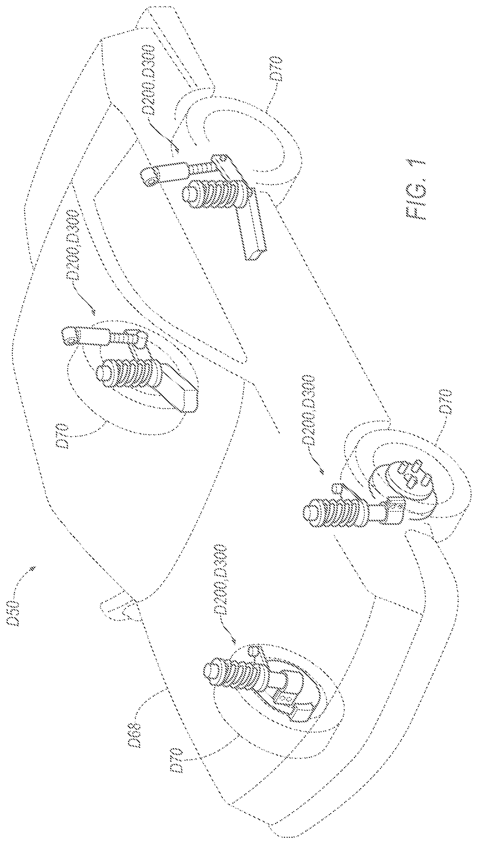
is a perspective view of a vehicle having a plurality of damper assemblies.
is a perspective view of one of the damper assemblies.
is an exploded view of components of the damper assembly.
is a continuation of the exploded view of .
is a continuation of the exploded view of .
is a continuation of the exploded view of .
is a cross-section of a portion of the damper assembly.
is an exploded view of components of another damper assembly.
is a continuation of the exploded view of .
is a continuation of the exploded view of .
is a cross-section of a portion of the damper assembly of .
is an end view of components of the damper assembly of .
is an end view of components of the damper assembly of .
is an exploded view of a portion of the damper assembly with alternate components.
is a cross section of the portion the damper assembly with alternate components of .
is an exploded view of a portion of the damper assembly with alternate components.
is a cross section of the portion the damper assembly with alternate components of .
is an exploded view of a portion of the damper assembly with alternate components.
is a cross section of the portion the damper assembly with alternate components of .
is the cross section of and illustrating a first fluid flow path when the damper assembly is moved toward a compressed position.
is the cross section of and illustrating a first fluid flow path when the damper assembly is moved toward the compressed position.
is the cross section of and illustrating a first fluid flow path when the damper assembly is moved toward the compressed position.
is the cross section of and illustrating a first fluid flow path when the damper assembly is moved toward the compressed position.
is the cross section of and illustrating a first fluid flow path when the damper assembly is moved toward the compressed position.
is an illustration of a force response curve D of the damper assembly moving toward the compressed position, the illustration identifying a first portion of the curve.
is the cross section of and illustrating the first fluid flow path when the damper assembly is moved toward the compressed position with the fluid flow rate and/or pressure differential above a first threshold.
is the cross section of and illustrating the first fluid flow path when the damper assembly is moved toward the compressed position with the fluid flow rate and/or pressure differential above the first threshold.
is the cross section of and illustrating the first fluid flow path when the damper assembly is moved toward the compressed position with the fluid flow rate and/or pressure differential above the first threshold.
is the cross section of and illustrating the first fluid flow path when the damper assembly is moved toward the compressed position with the fluid flow rate and/or pressure differential above the first threshold.
is the cross section of and illustrating the first fluid flow path when the damper assembly is moved toward the compressed position with the fluid flow rate and/or pressure differential above the first threshold.
is an illustration of the force response curve D of the damper assembly moving toward the compressed position with the fluid flow rate and/or pressure differential above the first threshold, the illustration identifying a second portion of the curve.
is the cross section of and illustrating the first fluid flow path and a second fluid flow path when the damper assembly is moved toward the compressed position with the fluid flow rate and/or pressure differential above a second threshold.
is the cross section of and illustrating the first fluid flow path and a second fluid flow path when the damper assembly is moved toward the compressed position with the fluid flow rate and/or pressure differential above the second threshold.
is an illustration of a force response curve D of the damper assembly moving toward the compressed position, the illustration identifying a third portion of the curve.
is the cross section of and illustrating a third fluid flow path and a fourth fluid flow path when the damper assembly is moved toward an extended position with the fluid flow rate and/or pressure differential above the second threshold.
is the cross section of and illustrating a third fluid flow path and a fourth fluid flow path when the damper assembly is moved toward the extended position with the fluid flow rate and/or pressure differential above the second threshold.
is the cross section of and illustrating the third fluid flow path when the damper assembly is moved toward the extended position with the fluid flow rate and/or pressure differential above the first threshold.
is the cross section of and illustrating the third fluid flow path when the damper assembly is moved toward the extended position with the fluid flow rate and/or pressure differential above the first threshold.
is the cross section of and illustrating the third fluid flow path when the damper assembly is moved toward the extended position with the fluid flow rate and/or pressure differential above the first threshold.
is an illustration of the force response curve D of the damper assembly moving toward the compressed position and a force response curve D of the damper assembly moving toward the compressed position.
DETAILED DESCRIPTION
With reference to , wherein like numerals indicate like parts throughout the several views, a damper assembly D 200 , D 300 for a vehicle D 50 includes a rod D 52 , D 54 elongated along an axis A 1 . The damper assembly D 200 , D 300 includes a piston D 56 , D 58 supported by the rod D 52 , D 54 , the piston D 56 , D 58 having a first surface D 60 and a second surface D 62 opposite the first surface D 60 . The piston D 56 , D 58 and the rod D 52 , D 54 define a passage D 64 , D 66 (illustrated in , and 11 - 13 ) between the piston D 56 , D 58 and the rod D 52 , D 54 , the passage D 64 , D 66 extending from the first surface D 60 of the piston D 56 , D 58 to the second surface D 62 of the piston D 56 , D 58 .
The vehicle D 50 may be any type of passenger or commercial vehicle such as a car, a truck, a sport utility vehicle, a crossover vehicle, a van, a minivan, a taxi, a bus, etc. The vehicle D 50 includes a body D 68 and a frame. The body D 68 and frame may be of a unibody construction. In the unibody construction, the body D 68 , e.g., rockers, serves as the vehicle frame, and the body D 68 (including the rockers, pillars, roof rails, etc.) is unitary, i.e., a continuous one-piece unit. As another example, the body D 68 and frame may have a body-on-frame construction (also referred to as a cab-on-frame construction). In other words, the body D 68 and frame are separate components, i.e., are modular, and the body D 68 is supported on and affixed to the frame. Alternatively, the body D 68 and frame may have any suitable construction. The body D 68 and/or the frame may be formed of any suitable material, for example, steel, aluminum, etc.
The damper assembly D 200 , D 300 controls motion of wheels D 70 of the vehicle D 50 relative to the body D 68 of the vehicle D 50 . The damper assembly D 200 , D 300 provides variable force to resist motion of the wheels D 70 relative to the body D 68 based on a speed of such motion. The damper assembly D 200 , D 300 defines an axis A 1 extending between ends D 71 of the damper assembly D 200 , D 300 . The damper assembly D 200 , D 300 may be elongated along the axis A 1 . The terms “axially,” “radially,” and “circumferentially” used herein are relative to the axis A 1 defined by the damper assembly D 200 , D 300 .
The damper assembly D 200 , D 300 is movable from a compressed position to an extended position, and vice versa. A distance between the ends D 71 of the damper assembly D 200 , D 300 is less in the compressed position than in the extended position. Springs or the like may urge the damper assembly D 200 , D 300 toward the extended position. Force applied to wheels D 70 of the vehicle D 50 , e.g., from bumps, potholes, etc., may urge to damper assembly D 200 , D 300 toward the compressed position.
The damper assembly D 200 , D 300 provides resistance to motion, i.e., resistance to moving toward the compressed position or the extended position, that is variable as a function of a speed of such motion. For example, and with reference to , 31 , 34 , 40 , a curve DC 1 and a curve DC 2 illustrate a functional relationship between a speed of movement of the damper assembly D 200 , D 300 and a resistance to such movement.
With reference to , the damper assembly D 200 , D 300 includes a cylinder D 72 that defines a chamber D 74 . The cylinder D 72 may be elongated along the axis A 1 of the damper assembly D 200 , D 300 , i.e., the cylinder D 72 may be hollow and tubular. The cylinder D 72 may be metal, or any suitable material. The chamber D 74 is filled with a fluid, e.g., an incompressible hydraulic fluid.
The rod D 52 , D 54 extends away from, and is movable relative to, the cylinder D 72 . The rod D 52 , D 54 is elongated along the axis A 1 of the damper assembly D 200 , D 300 . The rod D 52 , D 54 is moved relative to the cylinder D 72 when the damper assembly D 200 , D 300 is moved toward the compressed position or the extended position.
The rod D 52 , D 54 extends out of the chamber D 74 of the cylinder D 72 . For example, the cylinder D 72 may define an opening D 76 at an end of the cylinder D 72 , and the rod D 52 , D 54 may extend from within the chamber D 74 to outside the chamber D 74 through the opening D 76 at the end.
With reference to , the rod D 52 may include a rib D 78 . The rib D 78 may extend radially outward from the axis A 1 . The rib D 78 may be elongated along the axis A 1 . The rib D 78 may enable alignment of notches D 96 , D 120 , D 132 , D 142 , D 158 of the piston D 56 and discs D 108 , D 110 , D 124 a -D 124 e , D 126 a -D 126 e , D 140 , D 148 of the damper assembly D 200 , e.g., to provide the passages D 64 (further described below).
With reference to , the rod D 52 , D 54 may include one or more flats D 80 . The flats D 80 may be elongated along the axis A 1 . The flats D 80 reduce a size of an outer profile of the rod D 54 , e.g., to provide the passages D 66 between the flats D 80 and center openings D 84 , D 114 , D 130 , D 146 , D 154 of the piston D 58 and discs D 108 , D 110 , D 140 , D 124 a -D 124 e , D 126 a -D 126 e , D 140 , D 150 (further described below).
The passages D 64 , D 66 may be interchangeable. In other words, damper assembly D 200 may have a rod with flats (as described for rod D 54 ), and center openings of the various components of the damper assembly D 200 may be described for the center openings D 84 , D 114 , D 130 , D 146 , D 154 . Similarly, the damper assembly D 300 may include a rod with a rib, as described for the rod D 52 , and center openings of the various components of the damper assembly D 300 may include notches, e.g., as described for the notches D 96 , D 120 , D 132 , D 142 , D 158 .
The piston D 56 , D 58 is slidable within the chamber D 74 along the axis A 1 . The piston D 56 , D 58 is supported by the rod D 52 , D 54 , i.e., such that the piston D 56 , D 58 and rod D 52 , D 54 move relative to the cylinder D 72 generally in unison. For example, the piston D 56 , D 58 may include a center opening D 82 , D 84 . The rod D 52 , D 54 may be in the center opening D 82 , D 84 . The piston D 56 , D 58 may be fixed to the rod D 52 , D 54 , e.g., via a fastener D 86 , weld, friction fit, etc. The piston D 56 , D 58 may be metal, plastic, or any suitable material.
The piston D 56 , D 58 divides the chamber D 74 into a compression sub-chamber D 88 on one side of the piston D 56 , D 58 and a rebound sub-chamber D 90 on an opposite side of the piston D 56 , D 58 . Movement of the piston D 56 , D 58 within the chamber D 74 varies volumes of the compression sub-chamber D 88 and the rebound sub-chamber D 90 . For example, movement of the piston D 56 , D 58 when the damper assembly D 200 , D 300 is moved toward the compressed position decreases a volume of the compression sub-chamber D 88 and increases a volume of the rebound sub-chamber D 90 . As another example, movement of the piston D 56 , D 58 when the damper assembly D 200 , D 300 is moved toward the extended position increases the volume of the compression sub-chamber D 88 and decreases the volume of the rebound sub-chamber D 90 . Varying the volumes of the compression sub-chamber D 88 and the rebound sub-chamber D 90 generates a pressure differential therebetween and may cause fluid within the chamber D 74 to flow from one side of the piston D 56 , D 58 to the opposite side of the piston D 56 , D 58 , i.e., from the compression sub-chamber D 88 to the rebound sub-chamber D 90 , or vice versa. The fluid may flow from one side of the piston D 56 , D 58 to the opposite side of the piston D 56 , D 58 via one or more of passages D 92 , D 94 defined by the piston D 56 , D 58 and/or via the passages D 64 , D 66 defined by the piston D 56 , D 58 and the rod D 52 , D 54 .
Moving the damper assembly D 200 , D 300 toward the extended position decreases fluid pressure at the first surface D 60 and increases fluid pressure at the second surface D 62 . Moving the damper assembly D 200 , D 300 toward the compressed position increases fluid pressure at the first surface D 60 and decreases fluid pressure at the second surface D 62 . The first surface D 60 is between the second surface D 62 and the compression sub-chamber D 88 of the chamber D 74 . The second surface D 62 is between the first surface D 60 and the rebound sub-chamber D 90 of the chamber D 74 . As an example, the first surface D 60 may face the compression sub-chamber D 88 of the chamber D 74 and the second surface D 62 may face the rebound sub-chamber D 90 of the chamber D 74 .
The piston D 56 , D 58 defines one or more blow off passages D 92 , D 94 , e.g., one or more first blow off passages D 92 and one or more second blow off passages D 94 . The blow off passages D 92 , D 94 extend from the first surface D 60 of the piston D 56 , D 58 to the second surface D 62 of the piston D 56 , D 58 . The blow off passages D 92 , D 94 provide fluid communication between the compression sub-chamber D 88 and the rebound sub-chamber D 90 of the cylinder D 72 , i.e., such that fluid may flow from the compression sub-chamber D 88 to the rebound sub-chamber D 90 , or vice versa. The adjectives “first” and “second” are used as identifiers and are not intended to indicate significance or order.
The piston D 56 , D 58 and the rod D 52 , D 54 define the passages D 64 , D 66 therebetween. The passages D 64 , D 66 enable fluid flow from the compression sub-chamber D 88 to the rebound sub-chamber D 90 , and vice versa. The passages D 64 , D 66 may be spaced from each other circumferentially about the axis A 1 .
With reference to , the piston D 56 may define one or more notches D 96 . The notches D 96 may extend radially outward, e.g., away from the center opening D 82 . The notches extend from the second surface D 62 to the first surface D 60 . The notches may be spaced from each other about the axis A 1 . For example, the notches D 96 may be circumferentially between tabs D 98 that extend radially inward. The notches D 96 may define the passage D 64 between the piston D 56 and the rod D 52 . For example, the passages D 64 may extend axially along notches D 96 between the tabs D 98 . The rib D 78 of the rod D 52 may be in one of the notches D 96 . The rib D 78 in the notch D 96 provides a specific orientation between the piston D 56 and the rod D 52 , e.g., such that notches D 96 of the piston D 56 align with notches D 120 , D 132 , D 142 , D 158 of discs D 108 , D 110 , D 124 a -D 124 e , D 126 a -D 126 e , D 140 , D 148 of the damper assembly D 200 to define the passages D 64 .
With reference to , 9 , 11 and 13 , the passages D 64 , D 66 may be defined by the flats D 80 of the rod D 54 and the center opening of the piston D 58 . For example, each of the passages D 66 may extend axially between one of the flats D 80 and the center opening D 84 of the piston D 58 .
Returning to , 7 , 9 , and 11 , the second surface D 62 and/or the compressions surface may include ribs D 100 , D 102 , e.g., an inner rib D 100 and an outer rib D 102 . The ribs D 100 , D 102 extend along the axis A 1 . The inner rib D 100 is radially inward of the outer rib D 102 . The inner rib D 100 and outer rib D 102 may be elongated circumferentially about the axis A 1 . The inner rib D 100 and outer rib D 102 may completely surround the axis A 1 .
The ribs D 100 , D 102 at the second surface D 62 may define a first cavity D 104 , e.g., radially between the inner rib D 100 and the outer rib D 102 . The first cavity D 104 may be in fluid communication with the first blow off passages D 92 (and not the second blow off passages D 94 ) at the second surface D 62 . For example, the first blow off passages D 92 may be between the inner rib D 100 and the outer rib D 102 at the second surface D 62 . The ribs D 100 , D 102 at the first surface D 60 may define a second cavity D 106 , e.g., radially between the inner rib D 100 and the outer rib D 102 . The second cavity D 106 may be in fluid communication with the second blow off passages D 94 (and not the first blow off passages D 92 ) at the first surface D 60 . For example, the second blow off passages D 94 may be between the inner rib D 100 and the outer rib D 102 at the first surface D 60 .
The damper assembly D 200 , D 300 may include one or more blow off discs D 108 , D 110 , e.g., a first blow off disc D 108 and/or a second blow off disc D 110 . The blow off discs D 108 , D 110 , may be supported by the rod D 52 , D 54 . For example, each blow off disc D 108 , D 110 may include a center opening D 112 , D 114 and the rod D 52 , D 54 may be in the center openings D 112 , D 114 . The blow off discs D 108 , D 110 , decrease a resistance to movement in response to fluid flow past the blow off disc D 108 , D 110 , and/or a difference in fluid pressure on one side of the blow off disc 108 , D 110 , relative to an opposite side. The fluid flow and/or difference in fluid pressure may translate or flex the blow off disc D 108 , D 110 to create, and/or increase a size of, an opening D 116 , D 118 (illustrated in , 35 , and 36 ) through which fluid may flow. Increasing the size of the opening D 116 , D 118 decreases resistance to movement by permitting a greater amount of fluid to flow from one sub-chamber D 74 to the other sub-chamber D 74 . The amount of flex and/or translation of the blow off disc D 108 , D 110 , and the resulting increase in size of the opening D 116 , D 118 may be proportional to a rate of fluid flow and/or the pressure difference between the compression sub-chamber D 88 and the rebound sub-chamber D 90 of the cylinder D 72 . For example, the greater the rate of fluid flow and/or difference in fluid pressure, the greater the amount of flex and/or translation of the blow off disc D 108 , D 110 away from the piston D 56 , D 58 , providing a greater magnitude of increase of the size the opening D 116 , D 118 therebetween. A threshold rate of fluid flow and/or difference in fluid pressure may be required to flex and/or translate the blow off discs D 108 , D 110 . The blow off discs D 108 , D 110 , may not decrease resistance to movement until the threshold rate of fluid flow and/or difference in fluid pressure is achieved.
With reference to , 5 , 7 , and 12 the blow off discs D 108 , D 110 may define one or more notches D 120 . The notches D 120 may extend radially outward, e.g., away from the center openings D 112 . The notches D 120 may be spaced from each other about the axis A 1 . For example, the notches D 120 may be circumferentially between tabs D 122 that extend radially inward. The notches D 120 may define the passage D 64 between the blow off discs D 108 , D 110 and the rod D 52 . For example, the passages D 64 may extend axially along notches D 120 between the tabs D 122 . The rib D 78 of the rod D 52 may be in one of the notches D 120 . The rib D 78 in the notch D 120 provides a specific orientation between the blow off discs D 108 , D 110 and rod D 52 , e.g., such that notches D 120 of the blow off discs D 108 , D 110 align with notches D 96 , D 132 , D 142 , D 158 of the piston D 56 and discs D 124 a -D 124 e , D 126 a -D 126 e , D 140 , D 148 to define the passages D 64 .
With reference to , 11 and 13 , the passages D 66 may be defined by the flats D 80 of the rod D 52 , D 54 and the center opening D 114 of the blow off discs D 108 , D 110 . For example, each of the passages D 66 may extend axially between one of the flats D 80 and the center opening D 114 of the blow off discs D 108 , D 110 .
Returning to , the first blow off disc D 108 may be spaced from the second surface D 62 at the second blow off passages D 94 . Spacing the first blow off disc D 108 from the second surface D 62 at the second blow off passages D 94 permits fluid to freely flow into and out of the second blow off passages D 94 , e.g., without inhibition of such flow by the first blow off disc D 108 .
The first blow off disc D 108 selectively permits fluid flow out of the first blow off passages D 92 , i.e., depending on an amount and direction of fluid pressure applied to the first blow off disc D 108 . For example, the first blow off disc D 108 may selectively permit fluid flow through the first blow off passages D 92 in a first direction D 1 . The first blow off disc D 108 selectively permits fluid flow by controlling the size of the opening D 116 between the first blow off disc D 108 and the piston D 56 , D 58 .
When the damper assembly D 200 , D 300 is in the neutral state, the first blow off disc D 108 covers the first blow off passages D 92 at the second surface D 62 and restricts or inhibits fluid flow into, and out of, the first blow off passages D 92 . The first blow off disc D 108 in the neutral state may abut the second surface D 62 of the piston D 56 , D 58 at the first blow off passages D 92 , e.g., at distal ends the ribs D 100 , D 102 of the second surface D 62 .
When the damper assembly D 200 , D 300 is moved toward the compressed position the volume of the compression sub-chamber D 88 is reduced and the volume of the rebound sub-chamber D 90 is increased, thereby creating a pressure differential where fluid pressure is greater in the compression sub-chamber D 88 than in the rebound sub-chamber D 90 . Such pressure differential, and/or fluid flow caused by such pressure differential, may move the first blow off disc D 108 away from the piston D 56 , D 58 . Moving the first blow off disc D 108 away from the piston D 56 , D 58 creates the opening D 116 between the piston D 56 , D 58 and the first blow off disc D 108 . Fluid may flow out of the first blow off passages D 92 through the opening D 116 to the rebound sub-chamber D 90 of the cylinder D 72 . The first blow off disc D 108 may be moved away from the piston D 56 , D 58 only when the pressure differential is greater than a threshold amount. The threshold amount may be determined based on desired response characteristics of the damper assembly D 200 , D 300 , and the first blow off disc D 108 and other components of the damper assembly D 200 , D 300 may be designed, e.g., via geometry such as thickness, material type, etc., to flex at the threshold amount.
When the damper assembly D 200 , D 300 is moved toward the extended position the volume of the compression sub-chamber D 88 is increased and the volume of the rebound sub-chamber D 90 is decreased, thereby creating a pressure differential where fluid pressure is greater in the rebound sub-chamber D 90 than in the compression sub-chamber D 88 . Such pressure differential and/or fluid flow caused by such pressure differential may urge the first blow off disc D 108 toward the piston D 56 , D 58 and not create or enlarge the opening D 116 .
The second blow off disc D 110 may be spaced from the first surface D 60 at the first blow off passages D 92 . Spacing the second blow off disc D 110 from the first surface D 60 at the first blow off passages D 92 permits fluid to freely flow into and out of the first blow off passages D 92 , e.g., without inhibition of such flow by the second blow off disc D 110 .
The second blow off disc D 110 selectively permits fluid flow out of the second blow off passages D 94 of the piston D 56 , D 58 , i.e., depending on an amount and direction of fluid pressure applied to the second blow off disc D 110 . For example, the second blow off disc D 110 may selectively permit fluid flow through the second blow off passages D 94 in a second direction D 2 opposite the first direction D 1 . The second blow off disc D 110 selectively permits fluid flow by controlling the size of the opening D 118 between the second blow off disc D 110 and the piston D 56 , D 58 .
When the damper assembly D 200 , D 300 is in the neutral state the second blow off disc D 110 covers the second blow off passage D 94 at the first surface D 60 and restricts or inhibits fluid flow into, and out of, the second blow off passage D 94 . The second blow off disc D 110 in the neutral state may abut the first surface D 60 of the piston D 56 , D 58 at the second blow off passage D 94 , e.g. at distal ends of the ribs D 100 , D 102 at the first surface D 60 .
When the damper assembly D 200 , D 300 is moved toward the extended position and pressure is greater in the rebound sub-chamber D 90 of the cylinder D 72 than in the compression sub-chamber D 88 , the second blow off disc D 110 may be moved away from the piston D 56 , D 58 and create the opening D 118 between the piston D 56 , D 58 and the second blow off disc D 110 . Fluid may flow out of the second blow off passage D 94 through the opening D 118 to the compression sub-chamber D 88 of cylinder D 72 . The second blow off disc D 110 may be moved away from the piston D 56 , D 58 only when the pressure differential and/or fluid flow rate is greater than a threshold amount. The threshold amount may be determined based on desired response characteristics of the damper assembly D 200 , D 300 , and the second blow off disc D 110 and other components of the damper assembly D 200 , D 300 may be designed, e.g., via geometry such as thickness, material type, etc., to flex at the threshold amount.
When the damper assembly D 200 , D 300 is moved toward the compressed position and fluid pressure is greater in the compression sub-chamber D 88 of the cylinder D 72 than in the rebound sub-chamber D 90 the second blow off disc D 110 may be urged toward the piston D 56 , D 58 , not creating or enlarging the opening between the piston D 56 , D 58 and the second blow off disc D 110 .
The damper assembly D 200 , D 300 may include one or more spring discs D 124 a -D 124 e , D 126 a -D 126 e , e.g., one or more first spring discs D 124 a -D 124 e and/or one or more second spring discs D 126 a -D 126 e . The spring discs D 24 a -D 124 e , D 126 a -D 126 e may be supported by the rod D 52 , D 54 . For example, the rod D 52 , D 54 may extend through center openings D 128 , D 130 of the spring discs D 124 a -D 124 e , D 126 a -D 126 e . The spring discs D 124 a -D 124 e , D 126 a -D 126 e are elastically deformable. For example, force applied to an outer edge of the spring discs D 124 a -D 124 e , D 126 a -D 126 e may cause the spring discs D 124 a -D 124 e , D 126 a -D 126 e to flex such that the outer edge is moved axially relative the respective center opening D 128 , D 130 of the spring disc D 124 a -D 124 e , D 126 a -D 126 e . The spring discs D 124 a -D 124 e , D 126 a -D 126 e are made from an elastically deformable material, e.g., spring steel, plastic having suitable elastic properties, etc.
With reference to , 5 and 7 , the spring discs D 124 a -D 124 e , D 126 a -D 126 e may define one or more notches D 132 that are circumferentially spaced around the axis A 1 between tabs D 134 , e.g., as described for the notches D 96 , D 120 and tabs D 98 , D 122 of the piston D 56 and the blow off disc D 108 , D 110 . The notches D 96 may define the passage D 64 between the spring discs and the rod D 52 , D 54 . For example, the passages D 64 may extend axially along notches D 132 between the tabs D 134 . The rib D 78 of the rod D 52 may be in one of the notches D 132 .
With reference to , the passages D 66 may be defined by the flats D 80 of the rod D 52 , D 54 and the center openings D 130 of the spring discs D 124 a -D 124 e , D 126 a -D 126 e . For example, each of the passages D 66 may extend axially between one of the flats D 80 and the center openings D 130 of the spring discs D 124 a -D 124 e , D 126 a -D 126 e.
The first spring discs D 124 a -D 124 e urge the first blow off disc D 108 toward the piston D 56 , D 58 , i.e., the first spring discs D 124 a -D 124 e increase an amount of force required to flex the first blow off disc D 108 away from the piston D 56 , D 58 . The second spring discs D 126 a -D 126 e urge the second blow off disc D 110 toward the piston D 56 , D 58 , i.e., the second spring discs D 126 a -D 126 e increase an amount of force required to flex the second blow off disc D 110 away from the piston D 56 , D 58 .
The spring discs D 124 a -D 124 e , D 126 a -D 126 e may progressively decrease in size as a function of the distance from the piston D 56 , D 58 along the axis A 1 . For example, the first spring disc D 124 a closest to the piston D 56 , D 58 may have a larger outer diameter than an outer diameter of the first spring disc D 124 b adjacent such first spring disc D 124 a , and so on. The first spring disc farthest D 124 e from the piston D 56 , D 58 may have a diameter smaller that diameters of the other first spring discs D 124 a -D 124 d . As another example, the spring discs D 124 a -D 124 e , D 126 a -D 126 e may be configured similar to a leaf spring.
The first spring disc D 124 a closest the piston D 56 , D 58 may abut the first blow off disc D 108 proximate the rod D 52 , D 54 . The second spring disc D 126 a closest the piston D 56 , D 58 may abut the second blow off disc D 110 proximate the rod D 52 , D 54 .
The spring discs D 124 a , D 126 a closest the piston D 56 , D 58 may be spaced from the blow off discs D 108 , D 110 at outer edges of the blow off discs D 108 , D 110 . For example, a first ring D 136 may be between the first spring disc D 124 a and the first blow off disc D 108 along the axis A 1 . As another example, a second ring D 138 may be between the second spring disc and the second blow off disc D 110 . The rings D 136 , D 138 may be circular or any suitable shape. The rings D 136 , D 138 may be metal, plastic, or any suitable material. The rings D 136 , D 138 provide internal preload forces to the spring discs D 124 a -D 124 e , D 126 a -D 126 e . The rings D 136 , D 138 may be radially outward of the passages D 64 , D 66 .
Each damper assembly D 200 , D 300 may include a pair of fulcrum discs D 140 . The fulcrum discs D 140 provide fulcrum points for the spring discs D 124 a -D 124 e , D 126 a -D 126 e . For example, one of the fulcrum discs D 140 may abut the smallest first spring disc D 124 e opposite the adjacent larger first spring disc D 124 d . Such fulcrum disc D 140 may have a smaller outer diameter than the abutting smallest first spring disc D 124 e . As another example, the other fulcrum disc D 140 may abut the smallest second spring disc D 156 e opposite the adjacent larger second spring disc D 126 d . Such fulcrum disc D 140 may have a smaller outer diameter than the smallest second spring disc D 126 e.
With reference to , 6 , 7 and 12 , the fulcrum discs D 140 may define one or more notches D 142 spaced from each other about the axis A 1 , e.g., circumferentially between tabs D 144 . The notches D 142 may define the passage D 64 between the fulcrum discs D 140 and the rod D 52 , e.g., the passages D 64 , D 66 may extend axially along notches D 142 between the tabs D 144 . The rib D 78 of the rod D 52 may be in one of the notches D 142 . The rib D 78 in the notch D 142 provides a specific orientation between the fulcrum discs D 140 and rod D 52 , e.g., such that notches D 142 of the fulcrum discs D 140 align with notches D 96 , D 120 , D 132 , D 158 of the piston D 56 and discs D 108 , D 110 , D 124 a -D 124 e , D 126 a -D 126 e , D 148 to define the passages D 64 .
With reference to , the passages D 66 may be defined by the flats D 80 of the rod D 54 and center openings D 146 of the fulcrum discs D 140 . For example, each of the passages D 66 may extend axially between one of the flats D 80 and the center openings D 146 of the fulcrum discs D 140 .
With reference to , 6 , 7 , and 10 - 13 , the damper assembly D 200 , D 300 may include or more flow disc D 148 , D 150 . The flow discs D 148 , D 150 may each include a recessed area D 152 . The recessed area D 152 may by thinner, e.g., along the axis A 1 , than an area of the flow disc D 148 , D 150 radially outward of the recessed area D 152 . The recessed area D 152 may surround a center opening D 154 of the flow disc D 148 , D 150 .
The flow disc D 148 , D 150 may include extensions D 156 . The extensions may extend along the axis A 1 away from the recessed area D 152 . The extensions D 156 may be radially elongated, e.g., to distal ends. The extensions D 156 may be thicker along the axis A 1 than the recessed area D 152 . The extensions D 156 may be spaced about the axis A 1 . The extensions D 156 may define slots D 158 therebetween. With reference to , the one of the extensions D 156 of the flow disc D 148 may define a notch D 157 , e.g., between tabs. The rib D 78 of the rod D 52 may be in the notch D 157 . The extensions D 156 may define slots D 158 therebetween.
The flow disc D 148 , D 150 is supported by the rod D 52 , D 54 . For example, the rod D 52 , D 54 may be in the center opening D 154 . The extensions D 156 of the flow disc D 148 , D 150 may abut the rod D 52 , D 54 .
A pair of the flow discs D 148 may be supported by the rod D 52 , D 54 , e.g., on opposite sides of the piston D 56 , D 58 , as illustrated in . The damper assembly D 200 , D 300 may include only a single flow disc D 150 , e.g., at the first surface D 60 and as illustrated in .
The flow disc D 148 , D 150 enables fluid flow into and out of the passages D 64 , D 66 , e.g., to and from the compression sub-chamber D 88 . For example, the flow disc D 148 , D 150 may define a radial passage D 160 in fluid communication with the passage D 64 , D 66 . The radial passage D 160 be defined radially along the recessed area D 152 and between the extensions D 156 . Fluid may flow along the radial passage D 160 to the passage D 64 , D 66 via the slots D 158 . The flow discs D 148 , D 150 may face the respective sub-chamber D 74 . For example, the flow disc D 148 at the second surface D 62 may face the rebound sub-chamber D 90 and the flow disc D 148 , D 150 at the first surface D 60 may face the compression sub-chamber D 88 .
With reference to , 11 , and 14 - 19 , the damper assembly D 300 may include a housing D 162 , D 262 , D 362 , D 462 defining a chamber D 164 . The housing D 162 , D 262 , D 362 , D 462 may include a bottom wall D 166 . The bottom wall D 166 may extend radially away from a center opening D 168 and circumferentially about the axis A 1 . The bottom wall D 166 may include a recessed area D 170 . The housing D 162 , D 262 , D 362 , D 462 may include extensions D 172 . The extensions D 172 may extend radially inward. The extensions D 172 may be circumferentially spaced from each other about the axis A 1 and define slots D 174 therebetween. The housing D 162 , D 262 , D 362 , D 462 may include an outer wall D 176 . The outer wall D 176 may extend along the axis A 1 , e.g., from the bottom wall D 166 . The outer wall D 176 may extend about the axis A 1 . The outer wall D 176 may completely surround the axis A 1 . The outer wall D 176 and the bottom wall D 166 may be monolithic, i.e., a one-piece unit without any fasteners, joints, welding, adhesives, etc., fixing the outer wall D 176 and the bottom wall D 166 to each other.
The housing D 162 and components therein may be replaced with one of the other housings D 262 , D 362 , D 462 . In other words, any of the housings D 162 , D 262 , D 362 , D 462 may included in the damper assembly D 300 . The housing D 162 is illustrated at the rebound sub-chamber D 90 and the flow disc D 150 at the compression sub-chamber D 88 . Alternatively, the housing D 162 may be at the compression sub-chamber D 88 and the flow disc D 150 at the rebound sub-chamber D 90 .
The housing D 262 , D 362 may include a restriction rib D 178 , illustrated in . The restriction rib D 178 may extend away from bottom wall D 166 of the housing D 262 , D 362 , e.g., along the axis A 1 and toward a check disc D 224 , D 228 , D 230 . The restriction rib D 178 may extend circumferentially about the axis A 1 . The restriction rib D 178 may surround the axis A 1 . The restriction rib D 178 may be radially between the outer wall D 176 and the center opening D 168 . The restriction rib D 178 may be radially between the outer wall D 176 and the recessed area D 170 .
The restriction rib D 178 may include one or more channels D 180 , illustrated in . The channels D 180 extend radially through the restriction rib D 178 . The channels D 180 enable fluid flow from one side of the restriction rib D 178 to an opposite side of the restriction rib D 178 .
Returning to , 11 , and 14 - 19 , the housing D 162 , D 262 , D 362 , D 462 may be supported by the rod D 54 . For example, the rod D 54 may be in the center opening D 168 of the bottom wall D 166 . The extensions D 172 may abut the rod D 54 . The chamber D 164 defined by the housing D 162 , D 262 , D 362 , D 462 is in fluid communication with the passage D 66 , e.g., via the slots D 174 of the housing D 162 , D 262 , D 362 , D 462 .
The damper assembly D 200 , D 300 may include a top disc D 182 , D 282 , D 382 , D 482 that may further define the chamber D 164 . The top disc D 182 , D 282 , D 382 , D 482 may be supported by the rod D 54 , e.g., via a center opening D 184 . The top disc D 182 , D 282 , D 382 , D 482 may be fixed to the outer wall D 176 of the housing D 162 , D 262 , D 362 , D 462 , e.g., via weld, etc. The chamber D 164 may be between the top disc D 182 , D 282 , D 382 , D 482 and the bottom wall D 166 . The top disc D 182 , D 282 , D 382 , D 482 may include one or more openings D 186 that permit fluid flow into and out of the chamber D 74 .
The top disc D 282 , D 382 may include a restriction rib D 188 , illustrated in . The restriction rib D 188 may extend away from top disc D 282 , D 382 , e.g., along the axis A 1 and toward the bottom wall D 176 . The restriction rib D 188 may extend circumferentially about the axis A 1 . The restriction rib D 188 may surround the axis A 1 . The restriction rib D 188 may be radially between the outer wall D 176 of the housing D 262 , D 362 and the openings D 186 of the top disc 282 , D 382 .
The restriction rib D 188 may include one or more channels D 190 , illustrated in . The channels D 190 extend radially through the restriction rib D 188 . The channels D 190 enable fluid flow from one side of the restriction rib D 188 to an opposite side of the restriction rib D 188 .
Returning to , 6 , 7 , 8 , 11 , 18 , and 19 , the damper assembly D 200 , D 300 may include one or more orifice discs D 192 , D 194 , D 196 , D 198 . Each orifice disc D 192 , D 194 , D 196 , D 198 defines one or more orifices D 208 . The orifices D 208 may be spaced circumferentially around the orifice discs D 192 , D 194 , D 196 , D 198 . The orifices D 208 permit fluid flow axially and/or radially relative to the axis A 1 of the damper assembly D 200 , D 300 . Each orifice D 208 may extend radially inward from outer edges of the respective orifice disc D 192 , D 194 , D 196 , D 198 , e.g., to the recessed area D 152 of the flow disc D 148 , D 150 such that fluid may flow from the orifice D 208 to the recessed area D 152 . The orifice discs D 192 , D 194 , D 196 , D 198 may be supported by the rod D 52 , D 54 and/or the piston D 56 , D 58 , e.g., via a center opening D 202 , D 204 . The center opening D 202 may include a notch D 206 . The rib D 78 of the rod D 52 may be in the notch D 206 .
With reference to , a first orifice disc D 192 may be spaced from the first flow disc D 148 , e.g., with a first spacer D 210 therebetween. A second orifice disc D 194 may be spaced from the second flow disc D 150 , e.g., with a second spacer D 212 therebetween. The spacers D 210 , D 212 may be rings or any suitable shape. The spacers D 210 , D 212 may be supported by the rod D 52 , e.g., via center openings D 214 of the spacers D 210 , D 212 . The center openings D 214 may include notches D 216 . The rib D 78 of the rod D 52 may be in the notch D 216 .
A first orifice disc D 196 and a second orifice disc D 198 may be in the chamber D 74 . With reference to , the first orifice disc D 196 may abut the top disc D 182 , and the second orifice disc D 198 may abut the bottom wall D 166 of the housing D 162 . Orifices D 208 of the first orifice disc D 196 may be in fluid communication with the openings D 186 of the top disc D 182 . Orifices D 208 of the second orifice disc D 198 may be in fluid communication with the slots D 174 of the housing D 162 . With reference to , orifice discs D 196 , D 198 may be spaced from the bottom wall D 166 of the housing D 462 and the top disc D 482 , e.g. with spacers D 218 therebetween.
Check discs D 220 , D 222 , D 224 , D 226 , D 228 , D 230 , illustrated in , 6 , 7 , 8 , and 14 - 65 selectively restrict fluid flow through the passage D 64 , D 66 defined by the rod D 52 , D 54 , the piston D 56 , D 58 , etc., depending on a direction and an amount of fluid pressure and/or speed of fluid flow applied to the check discs D 220 , D 222 , D 224 , D 226 , D 228 , D 230 . The check discs D 220 , D 222 , D 224 , D 226 , D 228 , D 230 selectively permit fluid through the passages D 64 , D 66 by controlling a size of openings D 232 , D 234 between the check disc D 220 , D 222 , D 224 , D 226 , D 228 , D 230 and another component of the damper assembly D 200 , D 300 , such as the flow disc D 148 , D 150 , the housing D 162 , D 262 , D 362 , D 462 , the top disc D 182 , D 282 , D 382 , D 482 , etc.
Check discs D 220 , D 222 , D 224 , D 226 , D 228 , D 230 increase a resistance to movement in response to fluid flow past the respective check disc D 220 , D 222 , D 224 , D 226 , D 228 , D 230 and/or a difference in fluid pressure on one side of the check disc D 220 , D 222 , D 224 , D 226 , D 228 , D 230 relative to an opposite side. The fluid flow and/or difference in fluid pressure may translate or flex the check disc D 220 , D 222 , D 224 , D 226 , D 228 , D 230 and decease a size of an opening D 232 , D 234 through which fluid may flow and thereby increase resistance to movement. For example, the check discs D 220 , D 222 , D 224 , D 226 , D 228 , D 230 may be movable from unflexed positions, illustrated in , 15 , 17 , and 19 , to flexed positions illustrated in . The check discs D 220 , D 222 , D 224 , D 226 , D 228 , D 230 may be supported by the rod D 52 , D 54 , e.g., via a center opening D 242 of each of the check discs D 220 , D 222 , D 224 , D 226 , D 228 , D 230 .
The amount of flex and/or translation of the check discs D 220 , D 222 , D 224 , D 226 , D 228 , D 230 (and the associated decrease in size of the opening D 232 , D 234 ) may be proportional to a rate of fluid flow and/or a pressure differential between the compression sub-chamber D 88 and the rebound sub-chamber D 90 of the cylinder D 72 . For example, the greater the rate of fluid flow and/or difference in fluid pressure, the greater the amount of flex and/or translation of the check disc D 220 , D 222 , D 224 , D 226 , D 228 , D 230 . A threshold rate of fluid flow and/or difference in fluid pressure may be required to flex and/or translate the check discs D 220 , D 222 , D 224 , D 226 , D 228 , D 230 . The check discs D 220 , D 222 , D 224 , D 226 , D 228 , D 230 may not increase resistance to movement until the threshold rate of fluid flow and/or difference in fluid pressure is achieved.
With reference to , the check discs D 220 , D 222 may be axially outboard of the orifice discs D 192 , D 194 . The check discs D 220 , D 222 may abut the orifice discs D 192 , D 194 . The first orifice disc D 192 may be between the first check disc D 220 and the first flow disc D 148 . The second orifice disc D 194 may be between the second check disc D 222 and the second flow disc D 148 . The orifice discs D 192 , D 194 may be spaced from the flow discs D 148 when the check discs D 220 , D 222 are in the unflexed positions. The orifice discs D 192 , D 194 may abut the flow disc D 148 when the check discs D 220 , D 222 are in the flexed positions, as illustrated in .
With reference to , 21 , 17 , and 19 , the check discs D 224 , D 226 , D 228 , D 230 may be in the chamber D 164 . For example, check discs D 224 , D 226 , D 228 , D 230 may be axially between the bottom wall D 166 and the top disc D 182 , D 282 , D 382 , D 482 . The check discs D 224 , D 226 , D 228 , D 230 may be spaced from the outer wall D 176 of the housing D 162 , D 262 , D 362 , D 462 , e.g., such that fluid may flow therebetween.
A single check disc D 224 in the chamber D 164 , as illustrated in , and may selectively restrict fluid flow through the passage D 66 in both the first direction D 1 and the second direction D 2 . The check disc D 224 may be between the first orifice disc D 196 and the second orifice disc D 198 , as illustrated in . Such check disc D 224 may be spaced from the orifice discs D 196 , D 198 , e.g., with spacers D 218 therebetween. The check disc D 224 may be spaced from the bottom wall D 166 and the top disc D 182 , D 382 , e.g., with spacers D 218 therebetween.
The check disc D 224 in the unflexed position may be spaced from the orifice discs D 1196 , D 198 in the unflexed position and may abut one of the orifice discs D 196 , D 198 in the flexed positions, as illustrated in , 27 , and 36 .
The check disc D 224 may be spaced from the top disc D 282 and the bottom wall D 166 of the housing D 262 in the unflexed position and may abut one of the top disc D 282 or the bottom wall D 166 in the flexed positions, as illustrated in , 28 , and 37 .
The check discs D 228 , D 230 in the unflexed position may be spaced from the top disc D 382 and the bottom wall D 166 of the housing D 362 in the unflexed position, the first check disc D 228 may abut the top disc D 382 in the flexed position, and the second check disc D 230 may abut the bottom wall D 166 in the flexed position as illustrated in , 29 , and 38 . The first check disc D 228 may include orifices D 236 . The orifices D 236 provide radial flow along the disc D 228 , D 230 , e.g., past the restriction ribs D 178 , D 188 . The orifices D 326 may be at the rib D 188 of the of the top disc D 382 , i.e., such that fluid may flow from one side of the rib D 188 to another via the orifices D 236 . The second check disc D 230 may include orifices D 238 . The orifices D 238 may be at the rib D 178 of the of the bottom wall D 166 , i.e., such that fluid may flow from one side of the rib D 178 to another via the orifices D 236 .
A pair of check discs D 224 , D 226 , D 228 , D 230 may be in the chamber D 164 , as illustrated in . The check discs D 228 , D 230 may abut each other, as illustrated in . The check discs D 224 , D 226 may be spaced from each other, e.g., with a spacer D 218 there between and as illustrated in . The check discs D 224 , D 226 may be between and abut the orifice discs D 192 , D 194 , D 196 , D 198 , also illustrated in .
The first check disc D 224 and the first orifice disc D 196 in the unflexed position may be spaced from the top disc D 482 and the second check disc D 226 and the second orifice disc D 198 in the unflexed position may be spaced from the bottom wall D 166 , as illustrated in . The first orifice disc D 196 may abut the top disc D 482 when the first check disc D 224 is in the flexed position, as illustrated in . The second orifice disc D 198 may abut the bottom wall D 166 when the second check disc D 226 is in the flexed position, as illustrated in .
Movement of the check disc D 220 , D 222 , D 224 , D 226 , D 228 , D 230 toward another component of the damper assembly D 200 , D 300 decreases the size of the opening D 232 , D 234 therebetween through which fluid may flow. Decreasing the size of the opening D 232 , D 234 increases resistance to motion provided the damper assembly D 200 , D 300 by limiting fluid flow through the passages D 64 , D 66 . The check discs D 220 , D 222 , D 224 , D 226 , D 228 , D 230 may be moved toward another component of the damper assembly D 200 , D 300 only when the pressure differential and/or rate of fluid flow is greater than a threshold amount. The threshold amount may be determined based on desired response characteristics of the damper assembly D 200 , D 300 , and the check discs D 220 , D 222 , D 224 , D 226 , D 228 , D 230 and other components of the damper assembly D 200 , D 300 may be designed, e.g., via geometry such as thickness, material type, etc., to flex at the threshold amount.
When the damper assembly D 200 , D 300 is moved toward the compressed position the check discs D 220 , D 222 , D 224 , D 226 , D 228 , D 230 may be moved toward another component of the damper assembly D 200 , D 300 , e.g., to the flexed positions, and selectively restrict fluid flow in the first direction D 1 . For example, the second check disc D 222 and the second orifice disc D 194 may be moved toward the second flow disc D 148 , as illustrated in . As another example, the check disc D 224 may be moved toward the top disc D 182 , D 282 as illustrated in . As another example, both check discs D 228 , D 230 may by moved toward the top disc D 382 , as illustrated in . As another example, the first check disc D 224 and the first orifice disc D 196 may be moved toward the top disc D 482 , as illustrated in .
When the damper assembly D 200 , D 300 is moved toward the extended position the check discs D 220 , D 222 , D 224 , D 226 , D 228 , D 230 may be moved toward another component of the damper assembly D 200 , D 300 , e.g., to the flexed positions, and selectively restrict fluid flow in the second direction D 2 . For example, the first check disc D 220 and the first orifice disc D 192 may be moved toward the first flow disc D 148 , as illustrated in . As another example, the check disc D 224 may be moved toward the bottom wall D 166 , as illustrated in 37. As another example, both check discs D 228 , D 230 may by moved toward the bottom wall D 166 , as illustrated in . As another example, the second check disc D 226 and the second orifice disc D 198 may be moved toward the bottom wall D 166 , as illustrated in .
The openings D 232 , D 234 between the check discs D 220 , D 222 , D 224 , D 226 and another component of the damper assembly D 200 , D 300 may be defined by the orifices D 208 of the orifice discs D 192 , D 194 , D 196 , D 198 when the check discs D 220 , D 222 , D 224 , D 226 , D 228 , D 230 are in the flexed positions. For example, a size of the openings D 232 , D 234 may be defined by a cross sectional area of the orifice D 208 , e.g., as measured perpendicularly to a radius along which the respective orifice D 208 extends.
The openings D 232 , D 234 between the check discs D 224 , D 226 and another component of the damper assembly D 300 may be defined by the channels D 180 , D 190 of the restriction ribs D 178 , D 188 when the check discs D 224 , D 226 are in the flexed positions. For example, a size of the openings D 232 , D 234 may be defined by a cross sectional area of the channel D 180 , D 190 , e.g., as measured perpendicularly to a radius along which the respective channel D 180 , D 190 extends.
The openings D 228 , D 230 between the check discs D 228 , D 230 and another component of the damper assembly D 300 may be defined by the orifices D 236 , D 238 of the check discs D 228 , D 230 when the check discs D 228 , D 230 are in the flexed positions. For example, a size of the openings D 232 , D 234 may be defined by a cross sectional area of the orifices D 236 , D 238 , e.g., as measured perpendicularly to a radius along which the respective orifices D 236 , D 238 extend.
Each damper assembly D 300 may include a preload spacer D 246 . The preload spacer D 246 may protect the discs D 108 , D 110 , D 140 , D 124 a -D 124 e , D 126 a -D 126 e , D 140 , D 150 . A thickness of the preload may increase or decrease space available for piston D 58 and discs D 108 , D 110 , D 140 , D 124 a -D 124 e , D 126 a -D 126 e , D 140 , D 150 . For example, a thicker preload spacer D 246 may provide relatively less space and a thinner preload spacers D 246 may provide relatively more space.
With reference to , first fluid flow paths DFF 1 A, DFF 1 B defined by the respective damper assemblies are illustrated. The first fluid flow paths DFF 1 A, DFF 1 B are defined when the respective damper assembly D 200 , D 300 is moved toward the compressed position. The first fluid flow paths DFF 1 A, DFF 1 B in illustrate the respective damper assembly D 200 , D 300 moved toward the compressed position when a fluid flow rate and/or a pressure differential between the compression sub-chamber D 88 and the rebound sub-chamber D 90 is less than a first threshold.
The first fluid flow path DFF 1 A illustrated in extends from the compression sub-chamber D 88 through the opening between the second check disc D 220 , D 222 , D 224 , D 226 , D 228 , D 230 and the second flow disc D 148 , D 150 to the passage D 64 , D 66 via the radial passage D 160 of the second flow disc D 148 , D 150 . From the passage D 64 , D 66 , the first fluid flow path DFF 1 A extends through the radial passage D 160 of the first flow disc D 148 , D 150 to the rebound sub-chamber D 90 via the opening between the first check disc D 220 , D 222 , D 224 , D 226 , D 228 , D 230 and the first flow disc D 148 , D 150 .
The first fluid flow path DFF 1 B illustrated in extends from the compression sub-chamber D 88 through the radial passage D 160 of the flow disc D 148 , D 150 to the passage D 64 , D 66 . From the passage D 64 , D 66 , the first fluid flow path flow into the chamber D 74 via the radial passage D 160 of the bottom wall D 166 of the housing D 162 , D 262 , D 362 , D 462 around the check disc D 220 , D 222 , D 224 , D 226 , D 228 , D 230 ( s ) to the rebound sub-chamber D 90 via the opening in the top disc D 182 , D 282 , D 382 , D 482 .
The first fluid flow paths DFF 1 A, DFF 1 B each define an area, e.g., perpendicular to the respective first fluid flow path DFF 1 A, DFF 1 B, through which fluid may flow. The defined area may be at narrowest portion of the respective first fluid flow path DFF 1 A, DFF 1 B. The defined area may include multiple areas. For example, the first fluid flow paths DFF 1 A, DFF 1 B may split into multiple sub-paths, e.g., with each sub-path extending through one of the passages D 64 , D 66 . The sub-paths may each have a sub-area at a narrowest portion of the respective sub-path, and the defined area of the respective first fluid flow path DFF 1 A, DFF 1 B may be a combination of the areas of the sub-paths. Flow through the first fluid flow paths DFF 1 A, DFF 1 B may provide bleed flow to equalize the pressure differential between the compression sub-chamber D 88 and the rebound sub-chamber D 90 .
When the fluid flow rate and/or pressure differential between the compression sub-chamber D 88 and the rebound sub-chamber D 90 is less than the first threshold, the areas defined by the first fluid flow paths DFF 1 A, DFF 1 B provide resistance to movement of the piston D 56 , D 58 by limiting a rate at which fluid may flow from the compression sub-chamber D 88 to the rebound sub-chamber D 90 . Such resistance is illustrated in by a section DX of the curve DC 1 .
With reference to , the respective damper assembly D 200 , D 300 is illustrated as moved toward the compressed position when the fluid flow rate and/or the pressure differential between the rebound sub-chamber D 90 and the compression sub-chamber D 88 is greater than the first threshold. The first threshold may be such that a magnitude of the curve DC 1 reaches a predetermined amount of response force within a predetermined amount of time. The predetermined amounts may be based on empirical testing, e.g., to optimize vehicle D 50 performance and/or occupant comfort.
When the fluid flow rate and/or the pressure differential are greater than the first threshold, the fluid flow along the first fluid flow path DFF 1 A, DFF 1 B moves the respective check disc D 220 , D 222 , D 224 , D 226 , D 228 , D 230 towards another component of the damper assembly D 200 , D 300 , e.g., to the flexed position. Moving the check disc D 220 , D 222 , D 224 , D 226 , D 228 , D 230 towards another component of the damper assembly D 200 , D 300 decreases the size of the opening therebetween.
For example, the second orifice disc D 192 , D 194 , D 196 , D 198 illustrated in may be moved into abutment with the second flow disc D 148 , D 150 and with the second check disc D 220 , D 222 , D 224 , D 226 , D 228 , D 230 abutting the second orifice disc D 192 , D 194 , D 196 , D 198 opposite the second flow disc D 148 , D 150 , thereby minimizing the size of the opening, e.g., to be generally equal to the radial flow area of the orifices D 208 of the of the second orifice disc D 192 , D 194 , D 196 , D 198 .
As another example, the check disc D 220 , D 222 , D 224 , D 226 , D 228 , D 230 illustrated in may moved into abutment with the first orifice disc D 192 , D 194 , D 196 , D 198 , thereby minimizing the size of the opening, e.g., to be generally equal to the radial flow area of the orifices D 208 of the of the first orifice disc D 192 , D 194 , D 196 , D 198 .
As another example, the check disc D 220 , D 222 , D 224 , D 226 , D 228 , D 230 illustrate in may be moved in the abutment with the top disc D 182 , D 282 , D 382 , D 482 , e.g., abutting the restriction rib D 178 , and thereby minimizing the size of the opening, e.g., to be generally equal to the radial flow area of the channel of the of the restriction rib D 178 .
As another example, the first check disc D 220 , D 222 , D 224 , D 226 , D 228 , D 230 illustrated in may be moved into abutment with the top disc D 182 , D 282 , D 382 , D 482 , e.g., abutting the restriction rib D 178 , and with the second check disc D 220 , D 222 , D 224 , D 226 , D 228 , D 230 abutting the first check disc D 220 , D 222 , D 224 , D 226 , D 228 , D 230 opposite the top disc D 182 , D 282 , D 382 , D 482 . Such movement minimizes the size of the opening, e.g., to be generally equal to the radial flow area of the opening of the first check disc D 220 , D 222 , D 224 , D 226 , D 228 , D 230 .
As yet another example, the first orifice disc D 192 , D 194 , D 196 , D 198 illustrated in may be moved into abutment with the top disc D 182 , D 282 , D 382 , D 482 and with the first check disc D 220 , D 222 , D 224 , D 226 , D 228 , D 230 abutting the first orifice disc D 192 , D 194 , D 196 , D 198 opposite the top disc D 182 , D 282 , D 382 , D 482 , thereby minimizing the size of the opening, e.g., to be generally equal to the radial flow area of the orifices D 208 of the of the first orifice disc D 192 , D 194 , D 196 , D 198 .
Decreasing and/or minimizing the size of the openings decreases the defined area of the respective first fluid flow path DFF 1 A, DFF 1 B, and increases resistance to movement of the respective damper assembly D 200 , D 300 by reducing the rate at which fluid may flow from the compression sub-chamber D 88 to the rebound sub-chamber D 90 . Such resistance is illustrated in by a section DY of the curve DC 1 .
With reference to , a second fluid flow path DFF 2 defined by each damper assembly D 200 , D 300 is illustrated. The second fluid flow path DFF 2 is defined when the respective damper assembly D 200 , D 300 is moved toward the compressed position and the fluid flow rate and/or the pressure differential between the compression sub-chamber D 88 and the rebound sub-chamber D 90 is greater than a second threshold. The second threshold may be greater than the first threshold such that a slope and/or magnitude of the curve DC 1 does not exceed a predetermined amount. The predetermined amount may be based on empirical testing, e.g., to optimize vehicle D 50 performance and/or occupant comfort.
When the fluid flow rate and/or pressure differential is above the second threshold the first blow off disc D 108 and the first spring discs D 124 a -D 124 e are urged away from the piston D 56 , D 58 and the opening therebetween is created. The second fluid flow path DFF 2 extends from the compression sub-chamber D 88 to the rebound sub-chamber D 90 via the first blow off passages D 92 and the opening between the piston D 56 , D 58 and the first blow off disc D 108 . The second fluid flow path DFF 2 defines an area through which fluid may flow. The defined area of the second fluid flow path DFF 2 may include multiple sub-areas.
The combined defined areas of the first fluid flow path DFF 1 A, DFF 1 B and the second fluid flow path DFF 2 reduce resistance to movement of the respective damper assembly D 200 , D 300 (relative to the defined area of just the first fluid flow path DFF 1 A, DFF 1 B) by increasing a rate at which fluid may flow from the compression sub-chamber D 88 to the rebound sub-chamber D 90 . Such resistance is illustrated in by a section DZ of the curve DC 1 .
With reference to , a third fluid flow path DFF 3 A, DFF 3 B and a fourth fluid flow path DFF 4 defined by the respective damper assemblies are illustrated. The third and fourth fluid flow paths DFF 3 A, DFF 3 B DFF 4 , may be defined when the respective damper assembly D 200 , D 300 is moved toward the extended position and the fluid flow rate and/or the pressure differential between the compression sub-chamber D 88 and the rebound sub-chamber D 90 is above the second threshold.
The third fluid flow path DFF 3 A illustrated in extends from the rebound sub-chamber D 90 to the compression sub-chamber D 88 via, the passages D 64 , D 66 , and the <paths> of the flow discs D 148 , D 150 the opening between the first check disc D 220 , D 222 , D 224 , D 226 , D 228 , D 230 and the first flow disc D 148 , D 150 , e.g., through the orifices D 208 of the first orifice disc D 192 , D 194 , D 196 , D 198 .
The third fluid flow path DFF 3 B illustrated in extends from the rebound sub-chamber D 90 to the compression sub-chamber D 88 via the opening in the top disc D 182 , D 282 , D 382 , D 482 , the chamber D 74 of the housing D 162 , D 262 , D 362 , D 462 , and the passages D 64 , D 66 . The third fluid flow path DFF 3 B illustrated in extends through the opening between the check disc D 220 , D 222 , D 224 , D 226 , D 228 , D 230 and the bottom wall D 166 of the housing D 162 , D 262 , D 362 , D 462 , e.g., via the orifice D 208 of the second orifice disc D 192 , D 194 , D 196 , D 198 . The third fluid flow path DFF 3 B illustrated in extends through housing D 162 , D 262 , D 362 , D 462 by way of the opening between the check disc D 220 , D 222 , D 224 , D 226 , D 228 , D 230 and the bottom wall D 166 of the housing D 162 , D 262 , D 362 , D 462 , e.g., via the channel of the restriction rib D 178 . The third fluid flow path DFF 3 B illustrated in extends through housing D 162 , D 262 , D 362 , D 462 by way of the opening between the check disc D 220 , D 222 , D 224 , D 226 , D 228 , D 230 and the bottom wall D 166 of the housing D 162 , D 262 , D 362 , D 462 , e.g., via the channel of the restriction rib D 178 . The third fluid flow path DFF 3 B illustrated in extends through housing D 162 , D 262 , D 362 , D 462 by way of the opening between the second check disc D 220 , D 222 , D 224 , D 226 , D 228 , D 230 and the bottom wall D 166 of the housing D 162 , D 262 , D 362 , D 462 , e.g., via the orifice D 208 of the second orifice disc D 192 , D 194 , D 196 , D 198 .
The fourth fluid flow path DFF 4 , illustrated in , extends from the rebound sub-chamber D 90 to the compression sub-chamber D 88 via the second blow off passages D 94 and the opening between the second blow off disc D 110 and the piston D 56 , D 58 .
With reference to , the curve DC 1 and the curve DC 2 are shown. The curve DC 1 indicates response force provided by the damper assembly D 200 , D 300 D 200 , D 300 moving toward the compressed position at increased speeds. The curve DC 2 indicates response force provided by the damper assembly D 200 , D 300 moving toward the extended position at increased speeds. The various components of the damper assembly D 200 , D 300 may be configured to control the curves DC 1 , DC 2 , i.e., to control an amount of responsive force provided by the damper assembly D 200 , D 300 at various speeds.
The curves DC 1 , DC 2 may be increased or decreased in slope and/or in magnitude proximate arrows DA and DA′, e.g., providing tuning for low speed movement of the damper assembly D 200 , D 300 . For example, increasing a stiffness of the check disc D 220 , D 222 , D 224 , D 226 , D 228 , D 230 , and/or increasing a size of the orifice D 208 of the orifice disc D 192 , D 194 , D 196 , D 198 , and/or increasing a size of the opening of the check disc D 220 , D 222 , D 224 , D 226 , D 228 , D 230 may decrease the slope and/or magnitude of the curve DC 1 proximate arrow DA. Similarly increasing a stiffness of the check disc D 220 , D 222 , D 224 , D 226 , D 228 , D 230 , and/or increasing a size of the orifice D 208 of the orifice disc D 192 , D 194 , D 196 , D 198 , and/or increasing a size of the opening of the check disc D 220 , D 222 , D 224 , D 226 , D 228 , D 230 may decrease the slope and/or magnitude of the curve DC 2 proximate arrow DA′. As another example, decreasing a stiffness of the check disc D 220 , D 222 , D 224 , D 226 , D 228 , D 230 , and/or decreasing a size of the orifice D 208 of the orifice disc D 192 , D 194 , D 196 , D 198 , and/or decreasing a size of the opening of the check disc D 220 , D 222 , D 224 , D 226 , D 228 , D 230 may increase the slope and/or magnitude of the curve DC 1 proximate arrow DA. Similarly decreasing a stiffness of the check disc D 220 , D 222 , D 224 , D 226 , D 228 , D 230 , and/or decreasing a size of the orifice D 208 of the orifice disc D 192 , D 194 , D 196 , D 198 , and/or decreasing a size of the opening of the check disc D 220 , D 222 , D 224 , D 226 , D 228 , D 230 may increase the slope and/or magnitude of the curve DC 2 proximate arrow DA′.
The curves DC 1 , DC 2 may be increased or decreased in slope and/or in magnitude proximate arrows DB and DB′. For example, increasing a stiffness of the first blow off disc D 108 may increase the slope and/or magnitude of the curve DC 1 proximate arrow DB. Similarly, increasing a stiffness of the second blow off disc D 110 may increase the slope and/or magnitude of the curve DC 2 proximate arrow DB′. As another example, decreasing the stiffness of the first blow off disc D 108 may decrease the slope and/or magnitude of the curve DC 1 proximate arrow DB. Similarly, decreasing stiffness of the second blow off disc D 110 may decrease the slope and/or magnitude of the curve DC 2 proximate arrow DB′.
The curves DC 1 , DC 2 may be increased or decreased in slope and/or in magnitude proximate arrows DC and DC′, e.g., providing tuning for mid speed movement of the damper assembly D 200 , D 300 . For example, decreasing a thickness of the ring D 136 may decrease the slope and/or magnitude of the curve DC 1 proximate arrow DC. Similarly, decreasing a thickness of the ring D 138 may decrease the slope and/or magnitude of the curve DC 2 proximate arrow DC′. As another example, increasing the thickness of the ring D 136 may increase the slope and/or magnitude of the curve DC 1 proximate arrow DC. Similarly, increasing the thickness of the ring D 138 may increase the slope and/or magnitude of the curve DC 2 proximate arrow DC′.
The curves DC 1 , DC 2 may be increased or decreased in slope and/or in magnitude proximate arrows DD and DD′. For example, increasing a stiffness of the first spring discs D 124 a -D 124 e may increase the slope and/or magnitude of the curve DC 1 proximate arrow DD. Similarly, increasing a stiffness of the second spring discs D 126 a -D 126 e may increase the slope and/or magnitude of the curve DC 2 proximate arrow DD′. As another example, decreasing the stiffness of the first spring discs D 124 a -D 124 e may decrease the slope and/or magnitude of the curve DC 1 proximate arrow DD. Similarly, decreasing the thickness of the second spring discs D 126 a -D 126 e may decrease the slope and/or magnitude of the curve DC 2 proximate arrow DD′.
The curves DC 1 , DC 2 may be increased or decreased in slope and/or in magnitude proximate arrows DE and DE′, e.g., to control high speed response. For example, decreasing a size of the first blow off passages D 92 may increase the slope and/or magnitude of the curve DC 1 proximate arrow DE. Similarly, decrease a size of the second blow off passages D 94 may increase the slope and/or magnitude of the curve DC 2 proximate arrow DE′. As another example, increasing the size of the first blow off passages D 92 may decrease the slope and/or magnitude of the curve DC 1 proximate arrow DE. Similarly, increasing the size the second blow off passages D 94 may decrease the slope and/or magnitude of the curve DC 2 proximate arrow DE′. Additionally or alternately, a restriction disc (not shown) that covers a portion of the respective blow off passage D 64 , D 66 and/or deifies an opening of a certain size may increase or decrease the slope and/or the magnitude of the curves C 1 and C 2 proximate arrows E and E′.
Although the curves DC 1 , DC 2 proximate the various arrows DA, DA′, DB, DB′, DC, DC′, DD, DD′, DE, DE′ are described individually, the curves DC 1 , DC 2 may be controlled based on a cumulative effect of the configuration of the various components. For example, configuring the damper assembly D 200 , D 300 D 20 to control the curves DC 1 , DC 2 proximate arrows DA, DA′, may also change the curves DC 1 , DC 2 , proximate the other arrows DB, DB′, DC, DC′, DD, DD′, DE, DE′.
The adjectives “first,” “second,” and “third” are used as identifiers and are not intended to indicate significance or order.
The disclosure has been described in an illustrative manner, and it is to be understood that the terminology which has been used is intended to be in the nature of words of description rather than of limitation. Many modifications and variations of the present disclosure are possible in light of the above teachings, and the disclosure may be practiced otherwise than as specifically described.
Figures (20)
Citations
This patent cites (75)
- US3038562
- US4512447
- US4953671
- US4972929
- US5018608
- US5106053
- US5129488
- US5226512
- US5293971
- US5316113
- US5332069
- US5413195
- US5497862
- US5529154
- US5988330
- US6340081
- US6382372
- US6460664
- US6474454
- US6634379
- US6668986
- US6672436
- US7322449
- US7694786
- US8042661
- US8302746
- US8820495
- US9182005
- US9249854
- US9261160
- US9291231
- US9297436
- US9410595
- US9587703
- US9631695
- US9777790
- US9845839
- US9982739
- US10012283
- US10203016
- US10544852
- US10619694
- US2005/0056505
- US2005/0056506
- US2005/0263363
- US2008/0041682
- US2008/0314704
- US2009/0242341
- US2009/0260938
- US2011/0147147
- US2012/0018264
- US2013/0025446
- US2013/0333993
- US2014/0048366
- US2014/0231199
- US2014/0252735
- US2014/0262655
- US2014/0265203
- US2014/0332332
- US2015/0041269
- US2015/0114774
- US2016/0146286
- US2016/0258504
- US2016/0356335
- US2018/0259029
- US2018/0355945
- US2019/0226546
- US2019/0271373
- US2019/0285130
- US2019/0331193
- US2020/0271186
- US2021/0054902
- US112017007198
- US100443884
- US2019069413