Corbel for a Coke Oven or Coke Oven Battery
Abstract
A corbel for a coke oven, including a gunblock section having a longitudinal through-bore arranged therein, the gunblock section having at least one substantially vertical though-bore in communication with the longitudinal through-bore. The gunblock section may be integral with a base. The gunblock section may also include a substantially vertical-angular channel open to a first end of the gunblock section and also open to a first side of the gunblock section.
Claims (13)
1. A corbel for a coke oven, comprising: a base having a first side and a second side; a gunblock section integral with said base, said gunblock section having a longitudinal through-bore extending from a first end to a second end, said gunblock section includes a top end extending therefrom, said top end having at least one recess disposed therein; at least one substantially vertical through-bore arranged within said gunblock section, said at least one substantially vertical through-bore in communication with said longitudinal through-bore, said at least one substantially vertical through-bore has a second opening disposed within said at least one recess; and, a substantially angular channel proximate said first end of the gunblock section, said substantially angular channel having an opening arranged within a group consisting of: said first side of said base; and, said second side of said base.
6. A corbel for a coke oven, comprising: a gunblock section, said gunblock section having a longitudinal through-bore extending from a first end to a second end, said gunblock section having a first side and a second side extending therefrom, said gunblock section includes a top end and a bottom end extending therefrom, said top end having at least one recess disposed therein; at least one substantially vertical through-bore arranged within said gunblock section, said at least one substantially vertical through-bore in communication with said longitudinal through-bore, said at least one substantially vertical through-bore has a second opening disposed within said at least one recess; and, a substantially angular channel proximate said first end of the gunblock section, said substantially angular channel having an opening arranged within a group consisting of: said first side; and, said second side.
10. A corbel for a coke oven, comprising: a gunblock section having a first end and a second end, said gunblock section having a longitudinal through-bore extending from said first end to said second end, said gunblock section having at least one substantially vertical through-bore therein, said at least one substantially vertical through-bore in communication with said longitudinal through-bore, said gunblock section further including at least one arrangement extending therefrom, said arrangement selected from a group consisting of: a base, said base having a first side and a second side extending therefrom, said first side having a shoulder arranged thereon, said second side having a shoulder arranged thereon; a base, said base having a first side and a second side extending therefrom, a substantially angular channel proximate said first end of the gunblock section, said substantially angular channel having an opening arranged within a group consisting of: said first side of said base; and, said second side of said base, said at least one substantially vertical through-bore has a second opening disposed within said at least one recess; and, a first side and a second side extending from said gunblock section, a substantially angular channel proximate said first end of the gunblock section, said substantially angular channel having an opening arranged within a group consisting of: said first side; and, said second side, said at least one substantially vertical through-bore has a second opening disposed within said at least one recess.
Show 10 dependent claims
2. The corbel for a coke oven recited in claim 1 , wherein said longitudinal through-bore includes a recess proximate said first end of said gunblock section; and, said longitudinal through-bore includes a lip extending therefrom and arranged proximate said second end of said gunblock section.
3. The corbel for a coke oven recited in claim 2 , wherein said recess of said longitudinal through-bore is arranged to accept a lip of a longitudinal through-bore of an adjacent corbel.
4. The corbel for a coke oven recited in claim 1 , wherein said first side of said gunblock section includes at least one ledge; and, said second side of said gunblock section includes at least one ledge, wherein said at least one ledge of said first side is arranged to accept a block thereon, and wherein said at least one ledge of said second side is arranged to accept a block thereon.
5. The corbel for a coke oven recited in claim 1 , wherein said substantially vertically-angular channel is closed by a second end of an adjacent corbel arranged to abut said first end of said corbel.
7. The corbel for a coke oven recited in claim 6 , wherein said longitudinal through-bore includes a recess proximate said first end of said gunblock section; and said longitudinal through-bore includes a lip extending therefrom and arranged proximate said second end of said gunblock section.
8. The corbel for a coke oven recited in claim 7 , wherein said recess of said longitudinal through-bore is arranged to accept a lip of a longitudinal through-bore of an adjacent corbel.
9. The corbel for a coke oven recited in claim 6 , wherein said first side of said gunblock section includes at least one ledge; and said second side of said gunblock section includes at least one ledge, wherein said at least one ledge of said first side is arranged to accept a block thereon, and wherein said at least one ledge of said second side is arranged to accept a block thereon.
11. The corbel for a coke oven recited in claim 10 , wherein said gunblock section has a top end, said top end having at least one recess disposed therein.
12. The corbel for a coke oven recited in claim 10 , wherein said longitudinal through-bore includes a recess proximate said first end of said gunblock section; and, said longitudinal through-bore includes a lip extending therefrom and arranged proximate said second end of said gunblock section.
13. The corbel for a coke oven recited in claim 12 , wherein said recess of said longitudinal through-bore is arranged to accept a lip of a longitudinal through-bore of an adjacent corbel.
Full Description
Show full text →
CROSS-REFERENCE TO RELATED APPLICATIONS
This application claims the benefit under Articles 4 and 8 of the Stockholm Act of the Paris Convention for the Protection of Industrial Property of U.S. Provisional Patent Application No. 63/262,565, filed on Oct. 15, 2021, and U.S. Provisional Patent Application No. 63/262,566, filed on Oct. 15, 2021, which applications are hereby incorporated by reference herein in their entireties.
FIELD
The present invention relates to coke ovens, and, more particularly, to a corbel for a coke oven. More specifically, the present invention relations to gunblock configurations for a corbel for a coke oven or coke coven battery.
BACKGROUND
Coke is typically produced by heating coal in a coke oven battery. This battery may have anywhere from 40 to over 100 side-by-side coking chambers or ovens separated from each other by heating walls. Gas is burned within the walls to heat the coal arranged in the ovens. The floor bricks of each oven rest upon corbels. A regenerator is located in an area below the corbels. The regenerator is filled with bricks that have a relatively large amount of surface area per volume, generally due to slots formed in the bricks. In the regenerator, exhaust waste heat is used to pre-heat incoming air as well as cool the exhaust waste heat prior to discharge. The slotted bricks are called checker bricks, and they facilitate the heat transfer from the exhaust waste heat to the combustion materials. The regenerator supports the corbels. In turn, the corbels support the coke oven floor bricks and the heating walls. The heating walls, floor bricks, and corbels have traditionally been made of silica brick.
However, current corbel designs are susceptible to leakage since current corbels are made of multiple blocks or modules. Specifically, the modules must be mortared together, which is time consuming and allows for undesirably large thermal expansion. The thermal expansion of the components leads to permanent gaps that allow the leakage of gas. Because of the large number of bricks traditionally used, there are hundreds, and sometimes thousands, of potential failure points in corbels constructed using the conventional techniques and bricks.
Moreover, current corbel designs do not allow for optimal air flow between the heating wall, specifically the flue, and the regenerator. Furthermore, current corbel designs are very difficult and time consuming to replace, and require a shut down in coke processing. The corbel component of the coke oven, specifically a gun-flue, or gun-fire, type coke oven. In gun-fire type ovens, the corbel usually houses a horizontal gas duct extending the length of the individual coke oven—this is known as the “gunblock”. The gunblock is typically a separate component which is then surrounded by a plurality of multiple blocks or modules which collectively form the corbel of a coke oven.
Thus, there is a long felt need for a corbel for a coke oven that improves air and gas flow between the flue and the regenerator, and facilitates easy replacement.
There is also a long felt need for a corbel for a coke oven having a gunblock section therein—eliminating multiple seams created by a plurality of blocks or modules secured around a typical corbel gunblock.
There is an additional long felt need for a corbel for a coke oven having a plurality of gunblock configurations in order to accommodate different coke oven repair or construction requirements while eliminating the need for excess blocks or modules.
There is a further long felt need for a corbel configuration having an integral gunblock, i.e., a gunblock section, thereby eliminating the need for excess blocks, or modules, to fully construct a corbel—decreasing construction, and/or repair, downtime.
SUMMARY
At the outset, the present invention is generally related to corbel blocks having a plurality of gunblock configurations, where each of the configurations include at least one substantially vertical through-bore in communication with a longitudinal through-bore located within a gunblock section of the corbel block. Each of the possible configurations of the present invention may include a plurality of components extending from and integral with the gunblock section, such as, a base, at least one shoulder, at least one ledge, at least one flue channel, or a combination thereof—allowing a plurality of different arrangements to be utilized for repair, or construction, of a coke oven or coke oven battery.
In some embodiments, the present invention generally comprises a corbel for a coke oven having a base, a gunblock section integral with the base, the gunblock section having a longitudinal through-bore extending from a first end to a second end, at least one substantially vertical through-bore arranged within the gunblock section, the at least one substantially vertical through-bore in communication with the longitudinal through-bore, and a pair of shoulders extending from the base, each of the pair of shoulders having a groove arranged therein.
In other embodiments, the present invention could also generally comprise a corbel for a coke oven having a base, the base having a first side and a second side, a gunblock section integral with the base, the gunblock section having a longitudinal through-bore extending from a first end to a second end, at least one substantially vertical through-bore arranged within the gunblock section, the at least one substantially vertical through-bore in communication with the longitudinal through-bore, and a substantially vertically-angular channel proximate the first end of the gunblock section and having an opening arranged within a group consisting of: the first side of the base and the second side of the base.
In further embodiments, the present invention could further generally comprise a corbel for a coke oven having a gunblock section, the gunblock section having a longitudinal through-bore extending from a first end to a second end, the gunblock section having a first side and a second side extending therefrom, at least one substantially vertical through-bore arranged within the gunblock section, the at least one substantially vertical through-bore in communication with the longitudinal through-bore, and a substantially vertically-angular channel proximate the first end of the gunblock section, the substantially vertically-angular channel having an opening arranged within a group consisting of: the first side; and, the second side.
In additional embodiments, the present invention may generally comprise a corbel for a coke oven, where the corbel comprises a gunblock section having a first end and a second end, the gunblock section having a longitudinal through-bore extending from the first end to the second end, the gunblock section having at least one substantially vertical through-bore therein, the at least one substantially vertical through-bore in communication with the longitudinal through-bore, the gunblock section further including at least one arrangement extending therefrom, the arrangement selected from a group consisting of: a base, the base having a first side and a second side extending therefrom, the first side having a shoulder arranged thereon, the second side having a shoulder arranged thereon; a base, the base having a first side and a second side extending therefrom, a substantially vertically-angular channel proximate the first end of the gunblock section, the substantially vertically-angular channel having an opening arranged within a group consisting of: the first side of the base; and, the second side of said base; and, a first side and a second side extending from the gunblock section, a substantially vertically-angular channel proximate the first end of the gunblock section, the substantially vertically-angular channel having an opening arranged within a group consisting of: the first side; and, the second side.
In even further embodiments, the present invention may provide a corbel for a coke oven, comprising a top surface including a first cavity and a second cavity, a bottom surface including a first protrusion extending therefrom, a front surface including a passageway formed therein, a rear surface, a first side surface, a second side surface, and a through-bore extending from the front surface to the rear surface, the through-bore in fluid communication with the first cavity and the second cavity.
In some still further embodiments, the second cavity is spaced apart from the first cavity. In some embodiments, at least one of the first cavity and the second cavity is arranged between and spaced apart from the first side surface and the second side surface. In some embodiments, the through-bore is arranged at least partially on the first protrusion. In some embodiments, the through-bore extends partially above the bottom surface and partially below the bottom surface. In some embodiments, at least one of the first cavity and the second cavity comprises a hole extending to the through-bore. In some embodiments, the front surface comprises a recess arranged around the through-bore, and the rear surface comprises a second protrusion arranged around the through-bore. In some embodiments, the passageway comprises a first end arranged at the first cavity, a second end arranged proximate the bottom surface, a first wall extending from the first end to the second end, and a second wall extending from the first end to the second end. In some embodiments, the first wall and the second wall form a width of the passageway, and the width increases from the first end to the second end. In some embodiments, at least one of the first wall and the second wall comprises a curvilinear portion extending from the first cavity, and a linear portion extending from the curvilinear portion to the second side surface. In some embodiments, at least one of the first side surface and the second side surface comprises a second protrusion extending therefrom in a first direction, the second protrusion spaced apart from the top surface in a second direction, the second direction perpendicular to the first direction, and a third protrusion extending from the second protrusion in the first direction. In some embodiments, the third protrusion comprises a first surface perpendicular to the bottom surface, and a second surface tapered from the first surface to the bottom surface.
In other additional embodiments, the present invention may provide for a corbel for a coke oven, comprising a first side surface, a second side surface, a top surface including a first cavity and a second cavity, a bottom surface including a first protrusion extending therefrom, a front surface including a passageway formed therein, the passageway extending along a curvilinear path from the first cavity to the second side surface, a rear surface, and a through-bore extending from the front surface to the rear surface, the through-bore in fluid communication with at least one of the first cavity and the second cavity.
In even further additional embodiments, the second cavity is spaced apart from the first cavity. In some embodiments, the through-bore is arranged at least partially on the first protrusion. In some embodiments, at least one of the first cavity and the second cavity comprises a hole extending to the through-bore. In some embodiments, the passageway comprises a first end arranged at the first cavity, a second end arranged proximate the bottom surface, a first wall extending from the first end to the second end, and a second wall extending from the first end to the second end. In some embodiments, the first wall and the second wall form a width of the passageway, and the width increases from the first end to the second end. In some embodiments, at least one of the first side surface and the second side surface comprises a second protrusion extending therefrom in a first direction, the second protrusion spaced apart from the top surface in a second direction, the second direction perpendicular to the first direction, and a third protrusion extending from the second protrusion in the first direction.
In further and additional embodiments, the present invention may provide for a coke oven battery, comprising a regenerator including a regenerator region formed between a plurality of pillars, a corbel arranged on at least one pillar of the plurality of pillars, the corbel including a top surface including a first cavity and a second cavity, a bottom surface including a first protrusion extending therefrom and engaged with the at least one pillar, a front surface including a passageway formed therein, a rear surface, a first side surface, a second side surface, and a through-bore extending from the front surface to the rear surface, the through-bore in fluid communication with the first cavity and the second cavity, a heating wall arranged at least partially on the top surface, the heating wall comprising at least one flue in fluid communication with at least one of the first cavity, the second cavity, and the passageway, and a floor engaged with at least one of the first side surface and the second side surface.
The object of the present invention is to generally provide for a corbel having an integrally-arranged gunblock section, where a plurality of components extend therefrom, allowing the present invention to be used in the construction and/or repair of coke oven batteries, such that the present invention eliminates the need for additional blocks, bricks, and/or modules, thereby creating: 1. fewer seams to prevent possible leaks; 2. utilization of fewer components during construction and/or repair by combining the traditionally-used blocks, modules, and/or bricks into an integral corbel having a plurality of configurations; and, 3. more efficient construction and/or repair by eliminating the need for the additional components in the assembly of a coke oven and/or coke oven battery.
These and other objects, features, and advantages of the present invention will become readily apparent upon a review of the following detailed description of the invention, in view of the drawings and appended claims.
BRIEF DESCRIPTION OF THE DRAWINGS
Various embodiments are disclosed, by way of example only, with reference to the accompanying schematic drawings in which corresponding reference symbols indicate corresponding parts, in which:
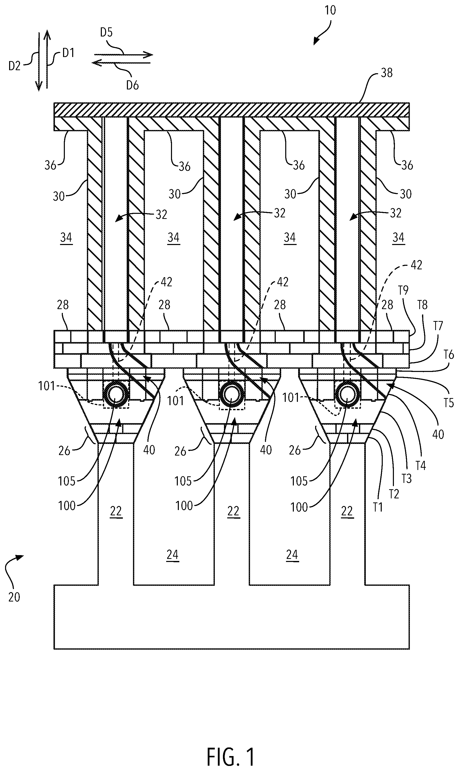
is an exemplary cross-sectional view of a coke oven battery in accordance with a first embodiment of the present invention;
is a partial perspective view of the coke oven battery shown in ;
A is a perspective view of a first embodiment of a corbel shown in ;
B is a skeleton perspective view of the corbel shown in A ;
C is a perspective view of an alternative embodiment of the corbel shown in A and 3 B ;
D is a top plan view of two corbels shown in C ;
is an exemplary cross-sectional view of a coke oven battery in accordance with a second embodiment of the present invention;
is a partial perspective view of the coke oven battery shown in ;
A is a perspective view of a second embodiment of a corbel shown in ;
B is a skeleton perspective view of the corbel shown in A ;
C is a perspective view of an alternative embodiment of the corbel shown in A and 6 B ;
D is a skeleton perspective view of the corbel shown in C ;
E is a perspective of two corbels shown in A having alternating channels;
F is a top plan view of the two corbels shown in E ;
is an exemplary cross-sectional view of a coke oven battery in accordance with a third embodiment of the present invention;
is a partial perspective view of the coke oven battery shown in ;
A is a perspective view of a third embodiment of a corbel shown in ; and,
B is a skeleton perspective view of the corbel shown in A .
DETAILED DESCRIPTION
At the outset, it should be appreciated that like drawing numbers on different drawing views identify identical, or functionally similar, structural elements. It is to be understood that the claims are not limited to the disclosed aspects.
Furthermore, it is understood that this disclosure is not limited to the particular methodology, materials and modifications described and as such may, of course, vary. It is also understood that the terminology used herein is for the purpose of describing particular aspects only, and is not intended to limit the scope of the claims.
Unless defined otherwise, all technical and scientific terms used herein have the same meaning as commonly understood to one of ordinary skill in the art to which this disclosure pertains. It should be understood that any methods, devices or materials similar or equivalent to those described herein can be used in the practice or testing of the example embodiments. The assembly of the present disclosure could be driven by hydraulics, electronics, pneumatics, and/or springs.
It should be appreciated that the term “substantially” is synonymous with terms such as “nearly,” “very nearly,” “about,” “approximately,” “around,” “bordering on,” “close to,” “essentially,” “in the neighborhood of,” “in the vicinity of,” etc., and such terms may be used interchangeably as appearing in the specification and claims. It should be appreciated that the term “proximate” is synonymous with terms such as “nearby,” “close,” “adjacent,” “neighboring,” “immediate,” “adjoining,” etc., and such terms may be used interchangeably as appearing in the specification and claims. The term “approximately” is intended to mean values within ten percent of the specified value.
It should be understood that use of “or” in the present application is with respect to a “non-exclusive” arrangement, unless stated otherwise. For example, when saying that “item x is A or B,” it is understood that this can mean one of the following: (1) item x is only one or the other of A and B; (2) item x is both A and B. Alternately stated, the word “or” is not used to define an “exclusive or” arrangement. For example, an “exclusive or” arrangement for the statement “item x is A or B” would require that x can be only one of A and B. Furthermore, as used herein, “and/or” is intended to mean a grammatical conjunction used to indicate that one or more of the elements or conditions recited may be included or occur. For example, a device comprising a first element, a second element and/or a third element, is intended to be construed as any one of the following structural arrangements: a device comprising a first element; a device comprising a second element; a device comprising a third element; a device comprising a first element and a second element; a device comprising a first element and a third element; a device comprising a first element, a second element and a third element; or, a device comprising a second element and a third element.
Moreover, as used herein, the phrases “comprises at least one of” and “comprising at least one of” in combination with a system or element is intended to mean that the system or element includes one or more of the elements listed after the phrase. For example, a device comprising at least one of: a first element; a second element; and, a third element, is intended to be construed as any one of the following structural arrangements: a device comprising a first element; a device comprising a second element; a device comprising a third element; a device comprising a first element and a second element; a device comprising a first element and a third element; a device comprising a first element, a second element and a third element; or, a device comprising a second element and a third element. A similar interpretation is intended when the phrase “used in at least one of:” is used herein.
It should be noted that the term “channel” (used in accordance with the components indicated by reference numerals 40 , 250 , and 350 ) is substantially the same as the phrase “vertically-angular channel”. As such, the terms may be interchangeably used. However, it should also be noted that the component indicated by the reference numeral 40 is not a component of the present invention, whereas components indicated by the reference numerals 250 and 350 are components of the present invention.
It should also be noted that the term “vertical through-bore” is used in accordance with the components indicated by reference numerals 42 , 110 , 110 A, 110 B, 210 A, 210 B, 310 A, and 310 B. However, it should be further noted that the component indicated by reference numeral 42 is not a component of the present invention, whereas the components indicated by reference numerals 110 , 110 A, 110 B, 210 A, 210 B, 310 A, and 310 B are components of the present invention.
Coke Oven Battery
Referring now to the figures, the following description should be taken in view of , 4 - 5 and 7 - 8 , as these illustrations generally illustrate a cross-sectional view of a coke oven battery and a partial perspective of the same, respectively. Specifically, generally illustrate a coke oven battery having the first embodiment of the present invention therein (corbel 100 ), where generally illustrate a coke oven battery having the second embodiment of the present invention therein (corbel 200 ), and generally illustrate a coke oven battery having the third embodiment of the present invention therein (corbel 300 ). The aforementioned illustrations generally depict the same components of a coke oven battery less structural differences provided by the alternative structural configurations of the various embodiments of the present invention. It should be noted that these illustrations of coke oven battery 10 are merely exemplary and one having ordinary skill in the art would understand that , 4 - 5 and 7 - 8 are merely representative to illustrate the structural benefits of utilizing corbels 100 , 200 , and 300 therein.
, 4 , and 7 are cross-sectional views of coke oven battery 10 , in accordance with corbels 100 , 200 , and 300 , respectively. Coke oven battery 10 generally comprises regenerator 20 and one or more ovens 34 .
Regenerator 20 comprises a plurality of piers or pillars 22 , which are spaced apart to form regenerator regions 24 . In some embodiments, each of pillars 22 comprise a plurality of bricks, modules, and/or blocks. Foundations 26 sit atop pillars 22 . Foundations 26 generally support corbels 100 , 200 , and 300 —either directly, or indirectly. Typically, foundation 26 comprises a plurality of bricks, modules, and/or blocks, i.e., a variety of structural components. In some embodiments, foundation 26 comprises a plurality of blocks arranged in a plurality of tiers, for example, two tiers T 1 and T 2 as shown in , or four tiers T 1 - 4 as shown in .
Corbels 100 , 200 , and 300 are arranged on top of pillars 22 and support the oven section of coke oven battery 10 . Specifically, corbels 100 , 200 , and 300 support floor 28 , heating walls 30 , and coal placed in ovens 34 , allowing air to flow between flues 32 and regenerator 20 , and also allowing gas to be injected into flues 32 . For example, gas is injected into corbels 100 , 200 , and 300 horizontally via horizontal through-bores 105 , 205 , and 305 of gunblock sections 101 , 102 , and 103 , respectively, and flows vertically through vertical through-bores 110 and 42 (of corbel 100 , where vertical through-bore 42 is not a component of corbel 100 but is in fluid communication with vertical through-bore 110 ), 210 A and 210 B (of corbel 200 ), 310 A and 310 B (of corbel 300 ) into flues 32 . As discussed herein, corbel 100 may have a pair of vertical through-bores, 110 A and 110 B (as shown in C ), which are in fluid communication with vertical through-bores 42 of coke oven battery 10 (shown in ). Air flows up through channels 40 , channels 250 (of corbel 200 ) and/or 350 (of corbel 300 ) and into flues 32 where it mixes with the fuel and combusts to heat heating walls 30 , thus cooking the coal arranged in ovens 34 transforming it into coke. Exhaust gasses are created from such combustion, these hot exhaust gases may flow down through channels 40 (of coke oven battery 10 when corbel 100 is used therein), 250 (of corbel 200 ) and 350 (of corbel 300 ) and into regenerator regions 24 , thereby preheating the incoming gas and/or air. Preheating gas and/or air as it flows into flues prior to combustion is desirable because it produces more efficient vaporization and higher combustion efficiency than cold fuel. It should be appreciated and understand by those having ordinary skill in the art that in some arrangements, coke oven battery 10 further comprises shut-off means (not illustrated) operatively arranged to selectively shut off the gas flow through one or more of the vertical through-bores. Since through-bores 110 (of corbel 100 ), through-bores 110 A and 110 B (of an alternatively configured corbel 100 ), 210 A and 210 B (of corbel 200 ), 310 A and 310 B (of corbel 300 ) are preferably associated with different flues 32 , such shut-off means (e.g., valves) allow the operator to control the temperature in each flue 32 and thus ovens 34 . Corbels 100 , 200 , and 300 will be described in greater detail, infra.
Floor 28 is arranged on and/or engaged with corbels 100 , 200 , and 300 (either directly or indirectly). Floor 28 is operatively arranged to support the coal in ovens 34 . In some embodiments, floor 28 comprises a plurality of blocks. Floor 28 may comprise a plurality of blocks arranged in a plurality of tiers, for example, six tiers T 4 - 9 in , or three tiers T 7 - 9 in . Heating walls 30 are arranged on corbels 100 , 200 , and 300 and/or floor 28 and comprise flues 32 arranged therein. Flues 32 are in fluid communication with through-bores 110 (of corbel 100 via vertical through-bore 42 ), 210 A and 210 B (of corbel 200 ), 310 A and 310 B (of corbel 300 ), and channels 40 , 250 , and 350 . Oven ceiling or ceilings 36 are arranged proximate the, or on, top of heating walls 30 . Thus, coking ovens 34 are formed by floor 28 , heating walls 30 , and oven ceiling 36 . Battery top 38 is arranged on top of heating walls 30 and may enclose flues 32 . In some embodiments, each flue 32 is in fluid communication with one channel ( 40 , 250 and/or 350 ) and at least one vertical through-bore, for example, vertical through-bores 42 , 210 A, and/or 310 A. In some embodiments, and as shown in , each flue 32 is in fluid communication with vertical through-bores 210 A or 310 A, vertical through-bores 210 B or 310 B (of an adjacently arranged corbel), and one channel ( 250 or 350 ). Specifically, one flue 32 is aligned with, in order in direction D 3 , vertical through-bore 210 B (or 310 B)—of a first corbel, channel 250 (or 350 )—of a second corbel arranged adjacently to the first corbel, and vertical through-bore 210 A (or 310 A)—of the second corbel. As discussed supra and shown in , it should be appreciated that corbel 100 may be alternatively arranged with to two (2) vertical through-bores and confine to the aforementioned arrangement-less the inclusion of a channel within corbel 100 , i.e., channel 40 is not a component of corbel 100 as shown in .
The arrangement of having a gas injection hole on either side of an air injection passageway provides a desirable combustion mixture of air and fuel. In some configurations, as shown in , heating walls 30 may be arranged solely on top of corbels 200 and 300 , namely, on a top surface. In some embodiments, heating walls 30 may be arranged at least partially on corbels 200 and 300 and at least partially on floor 28 . In some embodiments, heating walls 30 may be arranged solely on floor 28 .
Corbel: First Embodiment
The follow description pertains to the first embodiment of the present invention and should be taken in view of D , which illustrate a cross-sectional view of a coke oven battery in accordance with corbel 100 , a partial perspective view of the same, a front perspective view, a skeleton perspective view, an alternative embodiment of corbel 100 , and a top view of corbel 100 and an adjacent corbel 100 , respectively.
Corbel 100 generally comprises gunblock section 101 , base 102 , top end 102 A, first end 103 , second end 104 , through-bore 105 having first opening 106 and second opening 107 , first side 108 , second side 109 , vertical through-bore 110 . Gunblock section 101 includes the horizontal gas line, through-bore 105 , defined by first opening 106 arranged within first end 103 and second opening 107 arranged within second end 104 . Vertical through-bore 110 is in fluid communication with through-bore 105 and has an opening arranged within top end 102 A.
First side 108 is defined by tapered portion 120 A which extends from base 102 . Tapered portion 120 A terminates at shoulder 122 A. Extending from shoulder 122 A is first side 124 A of gunblock section 101 . Groove 126 A is disposed within shoulder 122 A is arranged to extend from first end 103 to second end 104 .
Second side 109 is defined by tapered portion 120 B which extends from base 102 . Tapered portion 120 B terminates at shoulder 122 B. Extending from shoulder 122 B is first side 124 B of gunblock section 101 . Groove 126 B is disposed within shoulder 122 B and is arranged to extend from first end 103 to second end 104 .
In an alternative embodiment of corbel 100 , illustrated in C , corbel 100 may have first vertical through-bore 110 A and second vertical through-bore 110 B, where each of through-bores 110 A and 110 B having openings arranged within top end 102 A and are both in fluid communication with through-bore 105 .
In some embodiments, through-bore 105 includes recess 106 A and lip 107 A, where recess 106 A is disposed proximate first opening 106 and lip 107 A extends from second opening 107 . As generally illustrated in D , lip 107 A of corbel 100 is arranged to be seated within recess 106 A of adjacent corbel 100 ′—creating a more efficient seal of through-bore 105 of corbel 100 and through-bore 105 of adjacent corbel 100 ′, thereby preventing and/or limiting gas leakage therebetween. It should be appreciated that the above-described arrangements of through-bore 105 of corbel 100 and through-bore 105 of adjacent corbel 100 ′ may also apply to corbels 200 and 300 (shown in A )—thereby preventing and/or limiting gas leakage therebetween.
It should be appreciated that an important aspect of corbel 100 is its configuration provides the tiers between foundation 26 and floor 28 , specifically the tiers proximate foundation 26 (T 3 ), as well as a portion of tier T 4 —as shown in . Specifically, corbel 100 provides tier T 3 and a portion of tier T 4 , in a single, integrally formed block. By providing a 30 portion of tier T 4 , and foundation 26 (which may be inclusive of tier T 3 ), a stronger and easier connection between corbel 100 and foundation 26 is formed. In some embodiments, base 102 of corbel 100 could also include tiers T 1 and T 2 , thereby eliminating the need for foundation 26 , as shown in .
It should be further appreciated that grooves 126 A and 126 B provide mating locations for respective protrusions arranged on the lower surfaces of blocks (tier T 4 ) placed on shoulders 122 A and 122 B, thereby preventing displacement of those blocks in directions D 5 and D 6 , i.e., similar to a tongue and groove connection. In some embodiments, grooves 126 A and 126 B could have perpendicularly arranged portions extending therefrom, i.e., cross-shaped, further preventing displacement of blocks, arranged thereon, in directions D 3 -D 6 .
It should also be appreciated that tapered portions 120 A and 120 B of corbel 100 , when arranged next to tapered portions 120 A and 120 b of an adjacent corbel 100 , assists in direct air into channel 40 (i.e., air traveling in direction D 1 ). It should also be appreciated that in some embodiments, corbel 100 may not comprise tapered portions 120 A and 120 B, whereas sides 108 and 109 are substantially planar surfaces which extend down to base 102 .
Corbel: Second Embodiment
The following description pertains to the second embodiment of the present invention and should be taken in view of F , which illustrate a cross-sectional view of a coke oven battery in accordance with corbel 200 , a partial perspective view of the same, a front perspective view, a skeleton perspective view, a perspective view of an alternative embodiment of corbel 200 , a skeleton perspective view of the alternative embodiment of corbel 200 , a perspective view of two abutting corbels 200 having alternating channels, and a top plan view of two abutting corbels 200 having alternating channels, respectively.
Corbel 200 generally comprises gunblock section 201 , base 202 , top end 202 A, first end 203 , second end 204 , through-bore 205 having first opening 206 and second opening 207 , first side 208 , second side 209 , first vertical through-bore 210 A, second vertical through-bore 210 B, and channel 250 . Gunblock section 201 includes the horizontal gas line, through-bore 205 , defined by first opening 206 arranged within first end 203 and second opening 207 arranged within second end 204 . First vertical through-bore 210 A and second vertical through-bore 210 B are in fluid communication with through-bore 205 and both have openings arranged within top end 202 A. Specifically, the openings of first vertical through-bore 210 A and second vertical through-bore 210 B are located within recesses 230 A and 230 B arranged within top end 202 A, respectively.
First side 208 is defined by tapered portion 240 A which extends from base 202 . Tapered portion 240 A terminates at first planar end 241 A. First planar end 241 A terminates at first ledge 242 A. Second planar end 243 A extends from first ledge 242 A. Second planar end 243 A terminates at second ledge 244 A. Third planar end 245 A extends from second ledge 244 A is. Third planar end 245 A terminates at top end 202 A.
Second side 209 is defined by tapered portion 240 B which extends from base 202 . Tapered portion 240 B terminates at first planar end 241 B. First planar end 241 B terminates at first ledge 242 B. Second planar end 243 B extends from first ledge 242 B. Second planar end 243 B terminates at second ledge 244 B. Third planar end 245 B extends from second ledge 244 B. Third planar end 245 B terminates at top end 202 A.
Channel 250 is disposed within first end 203 of corbel 200 , having an open portion on first end 203 . Channel 250 has two ends, the first end is disposed within recess 230 A and the second end is disposed within tapered portion 240 A, first planar end 241 A, and first ledge 242 A of first side 208 . It should be appreciated that channel 250 may alternatively be arranged to have its second end disposed within second side 209 (i.e., within tapered portion 240 B, first planar end 241 B, and first ledge 242 B) of corbel 200 —as illustrated in E and 6 F . It should be noted that the aforementioned configuration—alternatively arranged channels—may also apply to corbel 300 . As generally illustrated in F , the open portion of channel 250 (arranged on first end 203 ) is arranged to be closed, covered, and/sealed, by second end 204 of adjacent corbel 200 ′ that is abutting first end 203 of corbel 200 having channel 250 therein.
In some embodiments, channel 250 may not include an open portion disposed within first end 203 . As shown in C and 6 D , channel 250 may be disposed within corbel 200 . Corbel 200 may be utilized as an end corbel, or bookend, for a plurality of corbels that are abutted and formed together. The aforementioned configuration may also apply to corbel 300 .
It should be appreciated that an important aspect of corbel 200 is its configuration provides the tiers between foundation 26 and floor 28 , specifically the tiers proximate foundation 26 (T 3 and T 4 ), as well as the tiers proximate floor 28 (T 5 and T 6 )—as shown in . Specifically, corbel 200 provides tiers T 3 through T 6 , in a single, integrally formed block providing a stronger and easier connection between corbel 200 and foundation 26 , and eliminating seams created by individual blocks. Corbel 200 also provides for portions of tiers T 7 through T 9 . In some embodiments, base 202 of corbel 200 could also include tiers T 1 and T 2 , thereby eliminating the need for foundation 26 , as shown in .
Tier T 7 is arranged to be supported by first ledge 242 A (and/or first ledge 242 B). The respective block of tier T 7 is specifically arranged to be placed on first ledge 242 A (and/or first ledge 242 B) and abut second planar end 243 A (and/or second planar end 243 B), where second planar end 243 A prevents the block of tier T 7 from moving in directions D 5 or D 6 .
Floor 28 , comprising tier T 8 and/or T 9 , is arranged to be supported by second ledge 244 A (and/or second ledge 244 B). The respective block, or blocks, of floor 28 , are specifically arranged to be placed on second ledge 244 A (and/or second ledge 244 B) and abut third planar end 245 A (and/or third planar end 245 B), where third planar end 245 A prevents the respective block, or blocks of floor 28 (tier T 8 and/or T 9 ) from moving in direction D 5 or D 6 .
The arrangement of corbel 200 provides for engagement and support of various tiers of floor 28 at different locations. This allows not only for increased support strength of floor 28 , but also for easy repair of floor 28 . For example, due to loading and unloading of coal/coke from ovens 34 , over time floor 28 exhibits damage thereto. Typically, this damage occurs on the top layer of floor, namely, tier T 9 . The design of corbel 200 (i.e., the support of two or more layers of floor 28 ) allows for tier T 9 to be easily removed and a new tier T 9 placed, without having to remove any other tier of floor 28 . Since the entirety of floor 28 does not need to be replaced, battery 10 down time and labor cost is saved.
Since corbel 200 generally comprises tiers T 3 through T 6 and portions of tiers T 7 through T 9 , existing seams created by the plurality of blocks that once comprised these tiers are eliminated—thereby eliminating potential leak points of gas, and/or heat.
Corbel: Third Embodiment
The follow description pertains to the third embodiment of the present invention and should be taken in view of B , which illustrate a cross-sectional view of a coke oven battery in accordance with corbel 300 , a partial perspective view of the same, a front perspective view and a skeleton perspective view of corbel 300 , respectively.
Corbel 300 generally comprises gunblock section 301 , top end 302 A, bottom end 302 B, first end 303 , second end 304 , through-bore 305 having first opening 306 and second opening 307 , first side 308 , second side 309 , first vertical through-bore 310 A, second vertical through-bore 310 B, and channel 350 . Gunblock section 301 includes the horizontal gas line, through-bore 305 , defined by first opening 306 arranged within first end 303 and second opening 307 arranged within second end 304 . First vertical through-bore 310 A and second vertical through-bore 310 B are in fluid communication with through-bore 305 and both have openings arranged within top end 302 A. Specifically, the openings of first vertical through-bore 310 A and second vertical through-bore 310 B located within recesses 330 A and 330 B arranged within top end 302 A, respectively.
First side 308 is defined by tapered portion 340 A which terminates at first planar end 341 A. First planar end 341 terminates at first ledge 342 A. Second planar end 343 A extends from first ledge 342 A. Second planar end 343 A terminates at second ledge 344 A. Third planar end 345 A extends from second ledge 344 A. Third planar end 345 A terminates at top end 302 A. First side 308 also includes base 360 A arranged proximate to bottom end 302 B. Protrusion 362 A extends from base 360 A and is further arranged to extend along base 360 A from first end 303 to second end 304 .
Second side 309 is defined by tapered portion 340 B which terminates at first planar end 341 B. First planar end 341 B terminates at first ledge 342 B. Second planar end 343 B extends from first ledge 342 B. Second planar end 343 B terminates at second ledge 344 B. Third planar end 345 B extends from second ledge 344 B. Third planar end 345 B terminates at top end 302 A. Second side 309 also includes base 360 B arranged proximate to bottom end 302 B. Protrusion 362 B extends from base 360 B and is further arranged to extend along base 360 B from first end 303 to 20 ) second end 304 .
Channel 350 is disposed within first end 303 of corbel 300 , having an open portion on first end 303 . Channel 350 has two ends, the first end is disposed within recess 330 A and the second end is disposed within tapered portion 340 A, first planar end 341 A, and first ledge 342 A of first side 308 . It should be appreciated that channel 350 may alternatively be arranged to have its second end disposed within second side 309 (i.e., within tapered portion 340 B, first planar end 341 B, and first ledge 342 B). The open portion of channel 350 is arranged to be closed and/or sealed by second end 304 of an adjacent corbel 300 that is abutting first end 303 of corbel 300 having channel 350 therein. Alternatively, channel 350 may be alternatively arranged within corbel 300 in a substantially similar arrangement of channel 250 of corbel 200 illustrated in E .
It should be noted that protrusions 362 A and 362 B are operatively arranged to engage recesses in foundation 26 . The engagement between protrusions 362 A and 362 B and the recesses in foundation 26 help with alignment and securement of corbel 300 during installation. Protrusions 362 A and 362 B forms a portion of tier T 4 and engages tier T 4 of foundation 26 , as shown in . The arrangement of protrusions 362 A and 362 B, extending from bases 360 A and 360 B and engaged with foundation 26 , provides for added securement of corbel 300 to foundation 26 . Protrusions 362 A and 362 B increase the surface area with which corbel 300 can be secured to foundation 26 and further eliminate shifting of corbel 300 in directions D 5 and D 6 .
It should be appreciated that an important aspect of corbel 300 is that its configuration provides the intermediate tiers between foundation 26 and floor 28 , as well as a portion of tier T 4 and possible tier T 3 (as shown in ). Specifically, corbel 300 provides tiers T 4 - 6 in a single, integrally formed block. By providing a portion of tier T 4 , namely, foundation 26 , a stronger and easier connection between corbel 300 and foundation 26 is formed.
Tier T 7 is arranged to be supported by first ledge 342 A (and/or first ledge 342 B). The respective block of tier T 7 is specifically arranged to be placed on first ledge 342 A (and/or first ledge 342 B) and abut second planar end 343 A (and/or second planar end 343 B), where second planar end 343 A prevents the block of tier T 7 from moving in direction D 5 or D 6 .
Floor 28 , comprising tier T 8 and/or T 9 , is arranged to be supported by second ledge 344 A (and/or second ledge 344 B). The respective block, or blocks, of floor 28 , are specifically arranged to be placed on second ledge 344 A (and/or second ledge 344 B) and abut third planar end 345 A (and/or third planar end 345 B), where third planar end 345 A prevents the respective block, or blocks of floor 28 (tier T 8 and/or T 9 ) from moving in direction D 5 or D 6 .
The arrangement of corbel 300 provides for engagement and support of various tiers of floor 28 at different locations. This allows not only for increased support strength of floor 28 , but also for easy repair of floor 28 . For example, due to loading and unloading of coal/coke from ovens 34 , over time floor 28 exhibits damage thereto. Typically, this damage occurs on the top layer of floor 28 , namely, tier T 9 . The design of corbel 300 (i.e., the support of two or more layers of floor 28 ) allows for tier T 9 to be easily removed and a new tier T 9 placed, without having to remove any other tier of floor 28 . Since the entirety of floor 28 does not need to be replaced, battery 10 down time and labor cost is saved.
Since corbel 300 generally comprises tiers T 5 and T 6 and portions of tiers T 4 and T 7 through T 9 , existing seams created by the plurality of blocks that once comprised these tiers are eliminated—eliminating potential leak points of gas, and/or heat.
The following description should be taken in view of all of the aforementioned figures. Tapered portions 120 A and 120 B (of corbel 100 ), 240 A and 240 B (of corbel 200 ), and 340 A and 340 B (or corbel 300 ) form a V-shape when combined with a tapered portion of an adjacent corbel. This V-shape configuration funnels air, traveling in direction D 1 , into channels 40 (of coke oven 10 having corbel 100 therein), 250 (of corbel 200 ), and 350 (of corbel 300 ).
In a preferred embodiment, the horizontal through-bore of the respective gunblock sections of corbels 100 , 200 , 300 will have a first end and a second end, defined by a respective opening. One of the openings will have a recessed portion and the opposite opening will have a lip portion, or protruding portion, extending therefrom. The recess and lip are arranged to facilitate easy connection between two corbels, whereas the lip portion of the horizontal through-bore is arranged to be seated within the recessed portion of a horizontal through-bore of an adjacently placed corbel, as discussed supra. This arrangement increases the sealed nature of fluidly-connected horizontal through-bores of respective gunblock sections.
It will be appreciated that various aspects of the invention and other features and functions, or alternatives thereof, may be desirably combined into many other different systems or applications. Various presently unforeseen or unanticipated alternatives, modifications, variations, or improvements therein may be subsequently made by those skilled in the art which are also intended to be encompassed by the following claims.
LIST OF REFERENCE NUMERALS
•
• 10 Coke oven battery • 20 Regenerator • 22 Pier or pillar • 24 Regenerator region • 26 Foundation • 28 Floor • 30 Heating wall • 32 Flue • 34 Oven • 36 Oven ceiling • 38 Battery top • 40 Channel of coke oven battery 10 • 42 Vertical through-bore of coke oven battery 10 • 100 Corbel • 101 Gunblock section of corbel 100 • 102 Base of corbel 100 • 102 A Top end of corbel 100 • 103 First end of corbel 100 • 104 Second end of corbel 100 • 105 Through-bore of gunblock section 101 • 106 First opening of through-bore 105 • 106 A Recess of first opening 106 • 107 Second opening of through-bore 105 • 107 A Lip of second opening 107 • 108 First side of corbel 100 • 109 Second side of corbel 100 • 110 Vertical through-bore of gunblock section 101 • 120 A Tapered portion of side 108 • 120 B Tapered portion of side 109 • 122 A Shoulder of side 108 • 122 B Shoulder of side 109 • 124 A First side of gunblock section 101 • 124 B Second side of gunblock section 101 • 126 A Groove of shoulder 122 A • 126 B Groove of shoulder 122 B • 200 Corbel • 201 Gunblock section of corbel 200 • 202 Base of corbel 200 • 202 A Top end of corbel 200 • 203 First end of corbel 200 • 204 Second end of corbel 200 • 205 Through-bore of gunblock section 201 • 206 First opening of through-bore 205 • 206 A Recess of first opening 206 • 207 Second opening of through-bore 205 • 207 A Lip of second opening 207 • 208 First side of corbel 200 • 209 Second side of corbel 200 • 210 A First vertical through-bore of gunblock section 201 • 210 B Second vertical through-bore of gunblock section 201 • 230 A First recess of top end 202 A • 230 B Second recess of top end 202 A • 240 A Tapered portion of side 208 • 240 B Tapered portion of side 209 • 241 A First planar end of side 208 • 241 B First planar end of side 209 • 242 A First ledge of side 208 • 242 B First ledge of side 209 • 243 A Second planar end of side 208 • 243 B Second planar end of side 209 • 244 A Second ledge of side 208 • 244 B Second ledge of side 209 • 245 A Third planar end of side 208 • 245 B Third planar end of side 209 • 250 Channel of corbel 200 • 300 Corbel • 301 Gunblock section of corbel 300 • 302 A Top end of corbel 300 • 302 B Bottom end of corbel 300 • 303 First end of corbel 300 • 304 Second end of corbel 300 • 305 Through-bore of gunblock section 301 • 306 First opening of through-bore 305 • 307 Second opening of through-bore 305 • 308 First side of corbel 300 • 309 Second side of corbel 300 • 310 A First vertical through-bore of gunblock section 301 • 310 B Second vertical through-bore of gunblock section 301 • 330 A First recess of top end 302 A • 330 B Second recess of top end 302 A • 340 A Tapered portion of side 308 • 340 B Tapered portion of side 309 • 341 A First planar end of side 308 • 341 B First planar end of side 309 • 342 A First ledge of side 308 • 342 B First ledge of side 309 • 343 A Second planar end of side 308 • 343 B Second planar end of side 309 • 344 A Second ledge of side 308 • 344 B Second ledge of side 309 • 345 A Third planar end of side 308 • 345 B Third planar end of side 309 • 350 Channel of corbel 300 • 360 A Base of side 308 • 360 B Base of side 309 • 362 A Protrusion of base 360 A • 362 B Protrusion of base 360 B • D 1 Direction • D 2 Direction • D 3 Direction • D 4 Direction • D 5 Direction • D 6 Direction • T 1 Tier • T 2 Tier • T 3 Tier • T 4 Tier • T 5 Tier • T 6 Tier • T 7 Tier • T 8 Tier • T 9 Tier
Figures (12)
Citations
This patent cites (21)
- US1528808
- US1739929
- US1754131
- US1775494
- US2132522
- US2294005
- US4069633
- US4364798
- US4565605
- US5061527
- US5137603
- US5676540
- US7827689
- US8266853
- US8640635
- US2010/0287871
- US2016/0264870
- US2016/0281983
- US0116178
- US155 316
- US2016 222758