Abstract
A vehicle includes: a pair of coupling brackets which face side surfaces of the battery and are fixed to inner wall surfaces of the pair of side frames, a support bracket which is coupled to inclined portions of the coupling brackets by fastening members, pin members which protrude from the inclined portions, a positioning hole with which the pin members are positioned, and a guide hole that communicates with the positioning hole and has a larger diameter than the positioning hole.
Claims (10)
1. A battery fixing structure for fixing a battery between a pair of side frames of a vehicle body, the battery fixing structure comprising: a pair of first brackets facing side surfaces of the battery and fixed to an inner wall surface of each of the pair of side frames; a second bracket which supports a bottom surface of the battery and is coupled, by a fastening member, to an inclined portion inclined with respect to a vertical direction of the pair of first brackets; a pin member protruding from the inclined portion of the first brackets; a positioning hole provided in the second bracket and in which the pin member is positioned; and a guide hole that communicates with the positioning hole in the second bracket and has a larger diameter than the positioning hole.
Show 9 dependent claims
2. The battery fixing structure according to claim 1 , wherein the guide hole is an elongated hole whose longitudinal direction extends along the vertical direction.
3. The battery fixing structure according to claim 1 , wherein the inclined portion includes an inclined surface inclined such that a distal end of the first brackets faces the center in a vehicle width direction of the vehicle body, and the pin member protrudes in the normal direction of the inclined surface.
4. The battery fixing structure according to claim 1 , wherein the second bracket is coupled to the inclined portion by a plurality of fastening members arranged at predetermined intervals, and the positioning hole and the guide hole are positioned between the plurality of fastening members.
5. The battery fixing structure according to claim 1 , wherein an outer circumferential surface of the pin member includes a groove along the circumferential direction, and a width of the groove is greater than a thickness of the second bracket.
6. The battery fixing structure according to claim 1 , wherein an outer circumferential surface of the pin member includes a groove along the circumferential direction, and the groove is formed at a position where the groove of the pin can be engaged with an edge of the guide hole.
7. The battery fixing structure according to claim 1 , wherein the second bracket includes: a support portion that supports the bottom surface of the battery; and a bent portion bent from an end portion of the support portion and coupled to the inclined portion.
8. The battery fixing structure according to claim 7 , wherein the bent portion is in contact with an inclined surface of the inclined portion, and the pin member protrudes in the normal direction from the inclined surface.
9. The battery fixing structure according to claim 1 , wherein the guide hole is positioned above the positioning hole in the vertical direction.
10. The battery fixing structure according to claim 1 , wherein the pin member is positioned by the positioning hole after being inserted into the guide hole when the battery is fixed to the side frames in an inverted state.
Full Description
Show full text →
CROSS-REFERENCE TO RELATED APPLICATIONS
The present application claims priority to Japanese Patent Applications number 2022-39869, filed on Mar. 15, 2022 contents of which are incorporated herein by reference in their entirety.
BACKGROUND OF THE INVENTION
The present disclosure relates to a battery fixing structure that fixes a battery to a vehicle body frame. In a vehicle having a frame structure such as a truck, a battery is fixed to a side frame or the like via a bracket.
In view of workability in fixing a battery, there has been proposed a system in which one bracket among a plurality of brackets is fixed to a side frame, and the other bracket is coupled to the one bracket with a fastening member while supporting the battery. In this case, the battery may fall off if the fastening member coupling these two brackets is loosened.
The present disclosure focuses on this point, and its object is to prevent a battery from falling off due to looseness of a fastening member.
An aspect of the present disclosure provides a battery fixing structure for fixing a battery between a pair of side frames of a vehicle body, the battery fixing structure including: a pair of first brackets facing side surfaces of the battery and fixed to an inner wall surface of each of the pair of side frames; a second bracket which supports a bottom surface of the battery and is coupled, by a fastening member, to an inclined portion inclined with respect to a vertical direction of the pair of first brackets; a pin member protruding from the inclined portion of one of the first brackets; a positioning hole provided in the second bracket and in which the pin member is positioned; and a guide hole that communicates with the positioning hole in the second bracket and has a larger diameter than the positioning hole.
BRIEF DESCRIPTION OF THE DRAWINGS
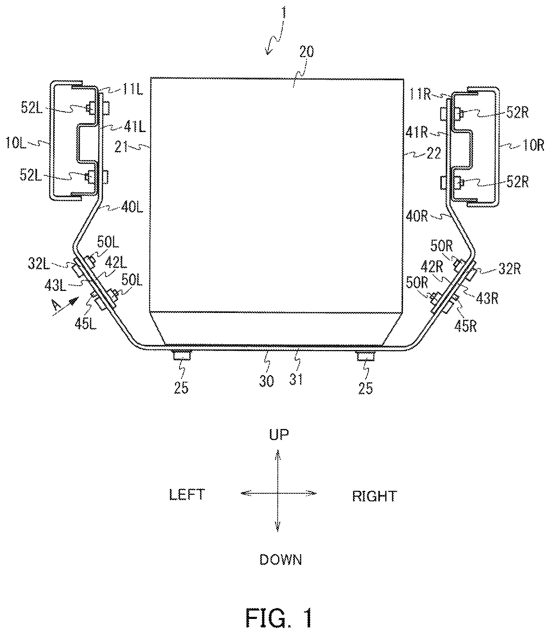
is a schematic diagram for illustrating a vehicle 1 having a fixing structure for a battery 20 according to an embodiment.
is an enlarged schematic diagram showing a portion viewed in a direction of an arrow A shown in .
is a schematic diagram showing a state in which the battery 20 is mounted in an inverted state.
A and 4 B are each a schematic diagram for illustrating a state in which a pin member 45 R is inserted through a guide hole 36 .
is a schematic diagram for illustrating a state in which a pin member 45 L is engaged with the guide hole 36 .
DETAILED DESCRIPTION OF THE INVENTION
Hereinafter, the present disclosure will be described through exemplary embodiments, but the following exemplary embodiments do not limit the invention according to the claims, and not all of the combinations of features described in the exemplary embodiments are necessarily essential to the solution means of the invention.
<Fixing Structure for a Battery>
A battery fixing structure according to an embodiment of the present disclosure will be described by referring to to 3 .
is a schematic diagram for illustrating a vehicle 1 having a fixing structure for a battery 20 according to the embodiment. is an enlarged schematic diagram showing a portion viewed in a direction of an arrow A shown in . is a schematic diagram showing a state in which the battery 20 is mounted in an inverted state.
As shown in , the vehicle 1 includes a pair of side frames 10 L and 10 R, the battery 20 , a support bracket 30 , and a pair of coupling brackets 40 L and 40 R. In the present embodiment, the coupling brackets 40 L and 40 R correspond to a pair of first brackets, and the support bracket 30 corresponds to a second bracket.
The pair of side frames 10 L and 10 R are provided along a front-rear direction of the vehicle 1 . That is, the longitudinal direction of the side frames 10 L and 10 R is along the front-rear direction. Here, the side frames 10 L and 10 R each have a closed cross section.
The battery 20 is a high-voltage storage battery mounted on the vehicle 1 , which is an electric vehicle. As shown in , the battery 20 is disposed between the pair of side frames 10 L and 10 R. A side surface 21 of the battery 20 faces the side frame 10 L, and a side surface 22 faces the side frame 10 R. The battery 20 is fixed to the side frames 10 L and 10 R via the support bracket 30 and coupling brackets 40 L and 40 R. When the battery 20 is mounted, the battery 20 is fixed to the side frames 10 L and 10 R in an inverted state, as shown in .
As shown in , a pair of coupling brackets 40 L and 40 R are disposed symmetrically on respective sides of the battery 20 along the vertical direction. The coupling bracket 40 L is opposed to the side surface 21 of the battery 20 , and the coupling bracket 40 R is opposed to the side surface 22 of the battery 20 . An upper end of the coupling bracket 40 L is fixed to an inner wall surface 11 L of the side frame 10 L by a fastening member 52 L, and an upper end of the coupling bracket 40 R is fixed to an inner wall surface 11 R of the side frame 10 R by a fastening member 52 R. The inner wall surfaces 11 L and 11 R are inner surfaces of the pair of side frames 10 L and 10 R in a vehicle width direction. Further, a lower end of the coupling bracket 40 L is fixed to a bent portion 32 L of the support bracket 30 by the fastening member 50 L, and a lower end of the coupling bracket 40 R is fixed to the bent portion 32 R of the support bracket 30 by the fastening member 50 R.
The coupling bracket 40 L includes a fixing portion 41 L, an inclined portion 42 L, and a pin member 45 L. As shown in , the fixing portion 41 L is coupled to the inner wall surface 11 L of the side frame 10 L. Specifically, the fixing portion 41 L is fixed to the inner wall surface 11 L by a plurality of fastening members 52 L. The fixing portion 41 L is positioned along the vertical direction.
As shown in , the inclined portion 42 L is a distal end of a portion extending in an approximate L-shape from the fixing portion 41 L. The inclined portion 42 L is formed to be inclined with respect to the vertical direction. The inclined portion 42 L has an inclined surface 43 L inclined such that the distal end thereof faces the center in the vehicle width direction.
As shown in , the pin member 45 L is provided such that it protrudes from the inclined portion 42 L. Specifically, the pin member 45 L protrudes in the normal direction of the inclined surface 43 L of the inclined portion 42 L. A groove 46 L (see ) along the circumferential direction is formed on an outer peripheral surface of the pin member 45 L. The width of the groove 46 L is greater than the thickness of the support bracket 30 , for example.
The coupling bracket 40 R includes a fixing portion 41 R, an inclined portion 42 R, and a pin member 45 R. As shown in , the fixing portion 41 R is coupled to the inner wall surface 11 R of the side frame 10 R. Specifically, the fixing portion 41 R is fixed to the inner wall surface 11 R by a plurality of fastening members 52 R. The fixing portion 41 R is positioned along the vertical direction.
As shown in , the inclined portion 42 R is a distal end of a portion extending in an approximate L-shape from the fixing portion 41 R. The inclined portion 42 R is formed to be inclined with respect to the vertical direction. The inclined portion 42 R has an inclined surface 43 R inclined such that the distal end thereof faces the center in the vehicle width direction.
As shown in , the pin member 45 R is provided such that it protrudes from the inclined portion 42 R. Specifically, the pin member 45 R protrudes in the normal direction of the inclined surface 43 R of the inclined portion 42 R. A groove 46 R (see ) along the circumferential direction is formed on an outer circumferential surface of the pin member 45 R. The width of the groove 46 R is greater than the thickness of the support bracket 30 , for example.
The support bracket 30 supports the battery 20 . The support bracket 30 is coupled to the inclined portion 42 L of the coupling bracket 40 L by the plurality of fastening members 50 L, and is coupled to the inclined portion 42 R of the coupling bracket 40 R by the plurality of fastening members 50 R. The support bracket 30 includes a support portion 31 and the bent portions 32 L and 32 R, as show in .
The support portion 31 is a central portion of the support bracket 30 . The support portion 31 supports a bottom surface of the battery 20 . The support portion 31 is fixed to the bottom surface of the battery 20 by a plurality of fastening members 25 .
The bent portion 32 L is a portion bent from the left end of the support portion 31 . The bent portion 32 L is in contact with the inclined surface 43 L of the inclined portion 42 L. The bent portion 32 L is coupled to the inclined portion 42 L of the coupling bracket 40 L. Specifically, the bent portion 32 L is fixed to the inclined portion 42 L by the plurality of fastening members 50 L arranged at predetermined intervals, as shown in .
The bent portion 32 L has a plurality of through holes 38 (see A and 4 B ) through which bolts of the plurality of fastening members 50 L are inserted. The bent portion 32 L is in contact with the inclined portion 42 L from which the pin member 45 L protrudes. The bent portion 32 L has a hole portion 34 ( ) through which the pin member 45 L of the coupling bracket 40 L is inserted and positioned. The hole portion 34 is positioned at the center of the plurality of through holes 38 .
The hole portion 34 includes a positioning hole 35 and a guide hole 36 , as shown in . The positioning hole 35 and the guide hole 36 are positioned between the plurality of fastening members 50 L. The hole portion 34 has a so-called key-hole shape in which the positioning hole 35 and the guide hole 36 communicate with each other. The guide hole 36 is positioned above the positioning hole 35 in the vertical direction.
The positioning hole 35 is a hole by which the pin member 45 is positioned, as shown in . A diameter of the positioning hole 35 is approximately the same as a diameter of the pin member 45 L.
The guide hole 36 functions as a guide for inserting the pin member 45 L into the hole portion 34 when the battery 20 is mounted. A diameter of the guide hole 36 is larger than the diameter of the positioning hole 35 . The guide hole 36 is an elongated hole whose longitudinal direction extends in the vertical direction. This facilitates insertion of the pin member 45 L through the guide hole 36 .
Similarly to the bent portion 32 L, the bent portion 32 R also has a hole portion 34 having the positioning hole 35 and the guide hole 36 . Since the hole portion 34 of the bent portion 32 R has the same configuration as the hole portion 34 of the bent portion 32 L described above, detailed description thereof will be omitted.
A flow of mounting the battery 20 on the vehicle 1 will be described below with reference to , 4 A, and 4 B . A and 4 B are each a schematic diagram for illustrating a state in which the pin member 45 R is inserted through the guide hole 36 . First, the side frames 10 L and 10 R are inverted. Next, the coupling brackets 40 L and 40 R are fixed to the side frames 10 L and 10 R. That is, the coupling bracket 40 L is fixed to the side frame 10 L by the fastening member 52 L, and the coupling bracket 40 R is fixed to the side frame 10 R by the fastening member 52 R. The present disclosure is not limited to the above, and the side frames 10 L and 10 R may be inverted after the coupling brackets 40 L and 40 R are first fixed to the side frames 10 L and 10 R.
Next, the battery 20 to which the support bracket 30 is fixed by the fastening members 25 is lowered, in an inverted state, from above the side frames 10 L and 10 R, as shown in . Then, the bent portions 32 L and 32 R of the support bracket 30 approach the coupling brackets 40 L and 40 R (see A ).
Thereafter, the pin members 45 L and 45 R are inserted through the guide holes 36 of the bent portions 32 L and 32 R of the support bracket 30 . For example, the pin member 45 R is inserted through the guide hole 36 of the bent portion 32 R, as shown in B . Since the diameter of the guide hole 36 is sufficiently larger than the diameter of the pin member 45 R, the pin member 45 R can be easily inserted through the guide hole 36 even with positional deviation between the pin member 45 R and the guide hole 36 .
When the battery 20 is further lowered, the pin members 45 L and 45 R are each positioned by engaging with a respective positioning hole 35 that communicates with a guide hole 36 . In this manner, when the battery 20 is fixed to the side frames 10 L and 10 R in the inverted state, the pin members 45 L and 45 R are each positioned by a positioning hole 35 after being inserted into a guide hole 36 . The support bracket 30 and the coupling brackets 40 L and 40 R are fixed by fastening the fastening members 50 L and 50 R in a state where the pin members 45 L and 45 R are each positioned in a positioning hole 35 . Thereafter, an operation of mounting the battery 20 is completed by returning the battery 20 to a non-inverted state, which is a state of being used, to be fixed to the side frames 10 L and 10 R.
In a state where the fastening of the fastening members 50 L and 50 R, which fix the coupling brackets 40 L and 40 R and the support bracket 30 , is insufficient, the fastening members 50 L and 50 R may be loosened and come off. On the other hand, in the present embodiment, since the guide holes 36 communicate with the positioning holes 35 in an upward direction, even if either of the fastening members 50 L and 50 R comes off, the pin members 45 L and 45 R are engaged with the guide holes 36 , thereby preventing the battery 20 from falling off
is a schematic diagram for illustrating a state in which the pin member 45 L is engaged with the guide hole 36 . Here, it is assumed that a plurality of fastening members 50 L that fix the coupling bracket 40 L and the support bracket 30 shown in are loosened and came off. In such a case, the bent portion 32 L of the support bracket 30 moves downward with respect to the coupling bracket 40 L. With this movement of the bent portion 32 L, the hole portion 34 also moves downward with respect to the pin member 45 L, and the pin member 45 L is hooked on the upper end of the guide hole 36 , as shown in . Specifically, the groove formed on the outer peripheral surface of the pin member 45 L is hooked on the upper end of the guide hole 36 . That is, the groove of the pin member 45 is formed at a position where it can be engaged with the edge of the guide hole 36 . This prevents the bent portion 32 L from moving downward and prevents the battery 20 from falling off.
In the above description, cases where the fastening member 50 L came off have been described. In a case where the fastening member 50 R comes off, the downward movement of the bent portion 32 R can be restricted due to the pin member 45 R hooking on the guide hole 36 of the bent portion 32 R, and therefore the falling off of the battery 20 can be prevented.
Effect of the Present Embodiment
The vehicle 1 of the embodiment described above includes the pair of coupling brackets 40 L and 40 R fixed to the side surface of the side frame 10 R and the side surface of the side frame 10 L, and a support bracket 30 supporting the battery 20 and fixed to (i) the inclined portion 42 L of the coupling bracket 40 L by the fastening member 50 L and (ii) the inclined portion 42 R of the coupling bracket 40 R by the fastening member 50 R. The coupling bracket 40 L has the pin member 45 L protruding from the inclined portion 42 L, and the coupling bracket 40 R has the pin member 45 R protruding from the inclined portion 42 R. Also, the support bracket 30 includes the positioning holes 35 with which the pin members 45 L and 45 R are positioned, and the guide holes 36 which communicate with the positioning holes 35 . The guide hole 36 has a larger diameter than the positioning hole 35 . In this way, when the battery 20 is mounted in the inverted state, the pin members 45 L and 45 R are inserted into the guide holes 36 and then positioned by the positioning holes 35 , whereby the battery 20 can be easily positioned at a desired position. On the other hand, when one of the fastening members 50 L and 50 R (here, the fastening member 50 L) is loosened and comes off, the pin member 45 L is hooked on the upper end of the guide hole 36 when the support bracket 30 moves downward with respect to the coupling bracket 40 L, thereby preventing the battery 20 from falling off
The present disclosure has been described above on the basis of the exemplary embodiments. The technical scope of the present disclosure is not limited to the scope explained in the above embodiments, and it is obvious to those skilled in the art that various changes and modifications within the scope of the invention may be made. An aspect to which such changes and modifications are added can be included in the technical scope of the present disclosure is obvious from the description of the claims.
Figures (5)
Citations
This patent cites (28)
- US4013300
- US4754827
- US7398849
- US8122989
- US8372530
- US8517131
- US8596682
- US8927128
- US8950536
- US9276243
- US9484562
- US10086880
- US10305151
- US10391881
- US10919398
- US11040610
- US12172509
- US12220979
- US2022/0416348
- US2023/0299410
- US238383
- USS37-007721
- USS57-045453
- USH02-121461
- USH04-129343
- USH08-324453
- US2017-065381
- US2018-103765