Liquid Discharging Head and Liquid Discharging Apparatus
Abstract
a first flow path communicating with the first common flow path; a second flow path communicating with the first common flow path at a position different from a position at which the first flow path communicates with the first common flow path; a third flow path communicating with the second common flow path; and a fourth flow path communicating with the second common flow path at a position different from a position at which the third flow path communicates with the second common flow path. In a first mode: through the first flow path, a liquid is supplied to the first common flow path; through the second flow path, the liquid is collected from the first common flow path; through the third flow path, the liquid is supplied to the second common flow path; and through the fourth flow path, the liquid is collected from the second common flow path.
Claims (13)
1. A liquid discharging head comprising: a plurality of individual flow paths corresponding to a plurality of nozzles; a first common flow path communicating with one side of the plurality of individual flow paths in common; a second common flow path communicating with another side of the plurality of individual flow paths in common; a first flow path communicating with the first common flow path; a second flow path communicating with the first common flow path at a position different from a position at which the first flow path communicates with the first common flow path; a third flow path communicating with the second common flow path; and a fourth flow path communicating with the second common flow path at a position different from a position at which the third flow path communicates with the second common flow path; wherein in a first mode through the first flow path, a liquid is supplied to the first common flow path, through the second flow path, the liquid is collected from the first common flow path, through the third flow path, the liquid is supplied to the second common flow path, and through the fourth flow path, the liquid is collected from the second common flow path.
Show 12 dependent claims
2. The liquid discharging head according to claim 1 , wherein the plurality of individual flow paths are placed in first direction; the first flow path communicates with the first common flow path at an end on one side in the first direction; and the second flow path communicates with the first common flow path at an end on another side in the first direction.
3. The liquid discharging head according to claim 2 , wherein: the third flow path communicates with the second common flow path at an end on the one side in the first direction; and the fourth flow path communicates with the second common flow path at an end on the another side in the first direction.
4. The liquid discharging head according to claim 2 , wherein: the third flow path communicates with the second common flow path at an end on the another side in the first direction; and the fourth flow path communicates with the second common flow path at an end on the one side in the first direction.
5. The liquid discharging head according to claim 1 , wherein the liquid discharging head fills the liquid in the first mode.
6. The liquid discharging head according to claim 5 , wherein a nozzle surface in which the plurality of nozzles are formed is sealed in the first mode.
7. The liquid discharging head according to claim 1 , wherein in a second mode through the first flow path, the liquid is supplied to the first common flow path, through the second flow path, the liquid is supplied to the first common flow path, through the third flow path, the liquid is collected from the second common flow path, and through the fourth flow path, the liquid is collected from the second common flow path.
8. The liquid discharging head according to claim 7 , wherein the liquid discharging head discharges the liquid in the second mode.
9. The liquid discharging head according to claim 7 , wherein a supply amount by which the liquid is supplied from the first flow path to the first common flow path per unit time in the first mode is greater than the supply amount by which the liquid is supplied from the first flow path to the first common flow path per unit time in the second mode.
10. The liquid discharging head according to claim 7 , wherein a supply amount by which the liquid is supplied from the first flow path to the first common flow path per unit time in the first mode is smaller than the supply amount by which the liquid is supplied from the first flow path to the first common flow path per unit time in the second mode.
11. The liquid discharging head according to claim 1 , wherein a supply amount by which the liquid is supplied from the first flow path to the first common flow path per unit time in the first mode is greater than the supply amount by which the liquid is supplied from the third flow path to the second common flow path per unit time in the first mode.
12. The liquid discharging head according to claim 1 , wherein in a third mode through the first flow path, the liquid is collected from the first common flow path, through the second flow path, the liquid is supplied to the first common flow path, through the third flow path, the liquid is collected from the second common flow path, and through the fourth flow path, the liquid is supplied to the second common flow path.
13. A liquid discharging apparatus comprising: the liquid discharging head according to claim 1 ; and a control device that controls the liquid discharging head in the first mode.
Full Description
Show full text →
The present application is based on, and claims priority from JP Application Serial Number 2022-116599, filed Jul. 21, 2022, the disclosure of which is hereby incorporated by reference herein in its entirety.
BACKGROUND
1. Technical Field
The present disclosure relates to a liquid discharging head and a liquid discharging apparatus.
2. Related Art
A liquid discharging apparatus such as an ink jet printer fills a liquid such as ink in a liquid discharging head and then discharges the liquid from the liquid discharging head. In a technology proposed for this type of liquid discharging head, a liquid is circulated in flow paths formed in the liquid discharging head to prevent a bubble from staying in the liquid and also to prevent the liquid from becoming more viscous. JP-A-2020-199695, for example, describes a technology related to a liquid discharging head that has: a plurality of individual flow paths corresponding to a plurality of nozzles; a common supply flow path communicating with one side of the plurality of individual flow paths in common; a common collection flow path communicating with another side of the plurality of individual flow paths in common; two supply ports through which the liquid is supplied to the common supply flow path; and two collection ports through which the liquid is collected from the common collection flow path. After the liquid is supplied from the two supply ports through the common supply flow path to the plurality of individual flow paths, the liquid is collected from the two collection ports through the common collection flow path.
In the technology in related art, however, the individual flow path has a higher flow path resistance than common flow paths such as the common supply flow path and common collection flow path, so there has been the risk that a bubble in a common flow path does not flow into an individual flow path but stays in the common flow path.
To address the above problem, a liquid discharging head of the present disclosure has: a plurality of individual flow paths corresponding to a plurality of nozzles; a first common flow path communicating with one side of the plurality of individual flow paths in common; a second common flow path communicating with another side of the plurality of individual flow paths in common; a first flow path communicating with the first common flow path; a second flow path communicating with the first common flow path at a position different from a position at which the first flow path communicates with the first common flow path; a third flow path communicating with the second common flow path; and a fourth flow path communicating with the second common flow path at a position different from a position at which the third flow path communicates with the second common flow path. In a first mode: through the first flow path, a liquid is supplied to the first common flow path; through the second flow path, the liquid is collected from the first common flow path; through the third flow path, the liquid is supplied to the second common flow path; and through the fourth flow path, the liquid is collected from the second common flow path.
A liquid discharging apparatus of the present disclosure has: the liquid discharging head described above; and a control device that controls the liquid discharging head in the first mode.
BRIEF DESCRIPTION OF THE DRAWINGS
illustrates an example of the structure of a liquid discharging apparatus according to an embodiment of the present disclosure.
illustrates an example of the structure of an ink supply device.
is an exploded perspective view illustrating an example of the structure of a liquid discharging head.
is a sectional view illustrating the example of the structure of the liquid discharging head.
is another sectional view illustrating the example of the structure of the liquid discharging head.
is a flowchart illustrating an example of operation of the liquid discharging apparatus.
illustrates an example of operation of the liquid discharging head in an ink filling mode.
illustrates an example of operation of the liquid discharging head in a reversed filling mode.
illustrates an example of operation of the liquid discharging head in a print mode.
illustrates an example of operation of the liquid discharging head in an ink filling mode in variation 1.
DESCRIPTION OF EXEMPLARY EMBODIMENTS
An embodiment of the present disclosure will be described below with reference to the drawings. The dimensions and scales of individual sections and portions in the drawings differ from their actual dimensions and scales, as appropriate. Since the embodiment described below is a preferred specific example in the present disclosure, various limitations that are desirable from a technical viewpoint have been added. However, the scope of the present disclosure is not limited to these forms unless, in the explanation below, there is a particular description that limits the present disclosure.
A. Embodiment
A liquid discharging apparatus 100 according to this embodiment will be described below.
1. Overview of the Liquid Discharging Apparatus
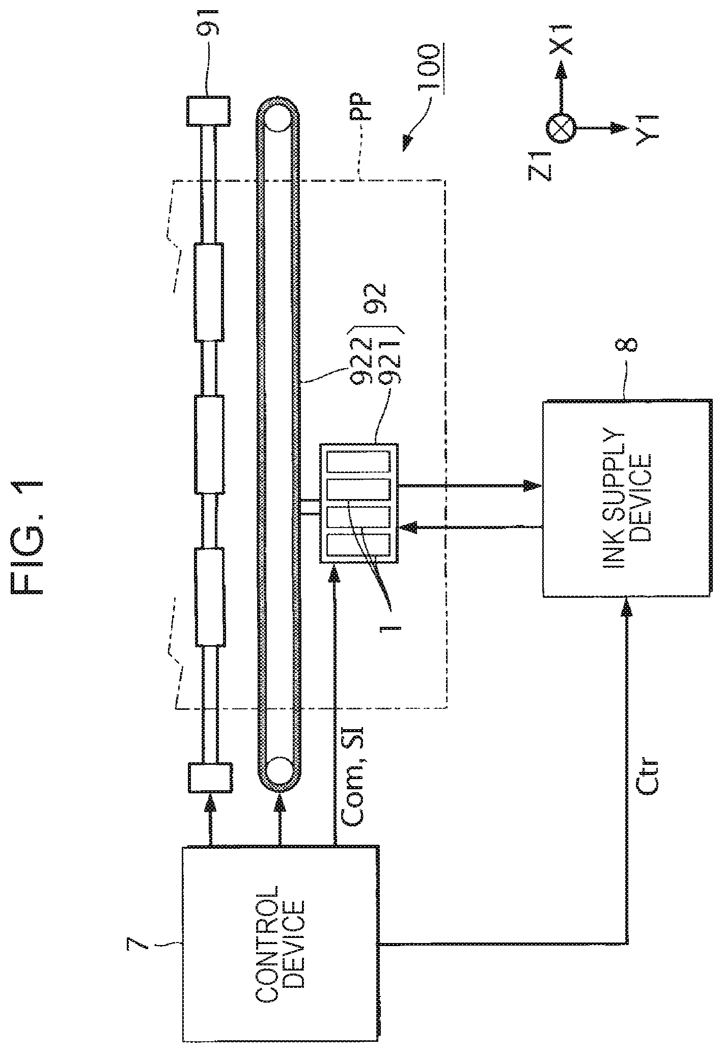
illustrates an example of the structure of the liquid discharging apparatus 100 according to this embodiment.
The liquid discharging apparatus 100 is an ink jet printing apparatus that discharges ink to a medium PP. The medium PP is typically a print sheet. However, a resin film, a fabric, and any other target eligible for printing can be used as the medium PP. Ink is an example of a liquid.
The liquid discharging apparatus 100 has a plurality of liquid discharging heads 1 , a control device 7 , an ink supply device 8 , a movement mechanism 91 , and a transport mechanism 92 .
The control device 7 includes a processing circuit such as, for example, a central processing unit (CPU) or a field-programmable gate array (FPGA) and a storage circuit such as a semiconductor memory. The control device 7 controls elements in the liquid discharging apparatus 100 .
The movement mechanism 91 transports the medium PP in the Y1 direction along the Y-axis under control of the control device 7 . The Y1 direction along the Y-axis and the Y2 direction opposite to the Y1 direction will be collectively referred to below as the Y-axis direction. The X1 direction along the X-axis crossing the Y-axis and the X2 direction opposite to the X1 direction will be collectively referred to below as the X-axis direction. The Z1 direction along the Z-axis crossing the X-axis and Y-axis and the Z2 direction opposite to the Z1 direction will be collectively referred to below as the Z-axis direction. When the inner product of a vector starting from one object and terminating at another object and a vector oriented in the X1 direction is positive, this is represented below as an object being present on the X1 side with respect to one object. Similarly, when the inner product of a vector starting from one object and terminating at another object and a vector oriented in the X2 direction is positive, this is represented below as an object being present on the X2 side with respect to one object. This is also true for the Y1 side, Y2 side, the Z1 side, and Z2 side.
In this embodiment, the X-axis, Y-axis, and Z-axis will be assumed to be mutually orthogonal, as an example. However, the present disclosure is not limited to this type of aspect. The X-axis, Y-axis, and Z-axis only need to cross one another.
The transport mechanism 92 bidirectionally moves the plurality of liquid discharging heads 1 in the X1 direction and X2 direction, under control of the control device 7 . The transport mechanism 92 has a storage case 921 in which the plurality of liquid discharging heads 1 are stored, and also has an endless belt 922 to which the storage case 921 is fixed. An ink supply device 8 may be stored in the storage case 921 together with the liquid discharging heads 1 .
The control device 7 supplies, to the liquid discharging heads 1 , a driving signal Com that drives the liquid discharging heads 1 and a control signal SI that controls the liquid discharging heads 1 . Each liquid discharging head 1 is driven in response to the driving signal Com under control of the control signal SI so as to discharge ink in the Z1 direction from part or all of a plurality of nozzles N provided in the liquid discharging head 1 . That is, the liquid discharging head 1 discharges ink from part of all of the plurality of nozzles N in conjunction with the transport of the medium PP by the movement mechanism 91 and the bidirectional movement of the liquid discharging heads 1 by the transport mechanism 92 , so that the discharged ink lands on the front surface of the medium PP and a desired image is formed on the front surface of the medium PP. The nozzle N will be described below with reference to .
The ink supply device 8 holds ink. The ink supply device 8 also supplies ink held in the ink supply device 8 to the liquid discharging heads 1 in response to a control signal Ctr supplied from the control device 7 . The ink supply device 8 also collects ink from the liquid discharging heads 1 in response to a control signal Ctr supplied from the control device 7 and causes the collected ink to flow back to the liquid discharging heads 1 .
In this embodiment, it will be assumed as an example that the ink supply device 8 holds four types of inks in cyan, magenta, yellow, and black. It will be also assumed as an example that the liquid discharging apparatus 100 has four liquid discharging heads 1 in correspondence to the four types of inks. To simplify the description below, however, attention will be focused on one of the four types of inks held in the ink supply device 8 and on a liquid discharging head 1 corresponding to the one type of ink, the liquid discharging head 1 being one of the four liquid discharging heads 1 included in the liquid discharging apparatus 100 .
2. Overview of the Ink Supply Device
The ink supply device 8 will be outlined below with reference to .
illustrates the ink supply device 8 .
As illustrated in , the ink supply device 8 has an ink holding container 81 , an ink supply container 82 , a pump G 0 , a pump G 11 , a pump G 12 , a pump G 21 , and a pump G 22 .
The ink holding container 81 holds ink. Possible examples of the ink holding container 81 include a cartridge attachable to and detachable from the liquid discharging apparatus 100 , a bag-shaped ink pack formed from a flexible film, and an ink tank that can be replenished with ink.
The pump G 0 supplies ink held in the ink holding container 81 to the ink supply container 82 in response to a control signal Ctr supplied from the control device 7 .
The ink supply container 82 temporarily holds ink supplied from the ink holding container 81 and ink collected from the liquid discharging head 1 .
The pump G 11 supplies ink held in the ink supply container 82 to the liquid discharging head 1 through a circulation flow path J 11 in response to a control signal Ctr supplied from the control device 7 . The pump G 11 also collects ink from the liquid discharging head 1 through the circulation flow path J 11 and supplies the collected ink to the ink supply container 82 , in response to a control signal Ctr supplied from the control device 7 . The circulation flow path J 11 is coupled to a coupling port H 11 formed in the liquid discharging head 1 . That is, through the circulation flow path J 11 and coupling port H 11 , the pump G 11 supplies ink to the liquid discharging head 1 and collects ink from the liquid discharging head 1 . The circulation flow path J 11 is an example of a first flow path.
The pump G 12 supplies ink held in the ink supply container 82 to the liquid discharging head 1 through a circulation flow path J 12 in response to a control signal Ctr supplied from the control device 7 . The pump G 12 also collects ink from the liquid discharging head 1 through the circulation flow path J 12 and supplies the collected ink to the ink supply container 82 , in response to a control signal Ctr supplied from the control device 7 . The circulation flow path J 12 is coupled to a coupling port H 12 formed in the liquid discharging head 1 . That is, through the circulation flow path J 12 and coupling port H 12 , the pump G 12 supplies ink to the liquid discharging head 1 and collects ink from the liquid discharging head 1 . The circulation flow path J 12 is an example of a second flow path.
The pump G 21 supplies ink held in the ink supply container 82 to the liquid discharging head 1 through a circulation flow path J 21 in response to a control signal Ctr supplied from the control device 7 . The pump G 21 also collects ink from the liquid discharging head 1 through the circulation flow path J 21 and supplies the collected ink to the ink supply container 82 , in response to a control signal Ctr supplied from the control device 7 . The circulation flow path J 21 is coupled to a coupling port H 21 formed in the liquid discharging head 1 . That is, through the circulation flow path J 21 and coupling port H 21 , the pump G 21 supplies ink to the liquid discharging head 1 and collects ink from the liquid discharging head 1 . The circulation flow path J 21 is an example of a third flow path.
The pump G 22 supplies ink held in the ink supply container 82 to the liquid discharging head 1 through a circulation flow path J 22 in response to a control signal Ctr supplied from the control device 7 . The pump G 22 also collects ink from the liquid discharging head 1 through the circulation flow path J 22 and supplies the collected ink to the ink supply container 82 , in response to a control signal Ctr supplied from the control device 7 . The circulation flow path J 22 is coupled to a coupling port H 22 formed in the liquid discharging head 1 . That is, through the circulation flow path J 22 and coupling port H 22 , the pump G 22 supplies ink to the liquid discharging head 1 and collects ink from the liquid discharging head 1 . The circulation flow path J 22 is an example of a fourth flow path.
3. Outline of the Liquid Discharging Head
The liquid discharging head 1 will be outlined below with reference to to 5 .
is an exploded perspective view illustrating the liquid discharging head 1 . is a sectional view taken along line IV-IV in . is a sectional view taken along line V-V in .
As illustrated in to 5 , the liquid discharging head 1 has a nozzle substrate 21 , compliance sheets CS 1 and CS 2 , a communication plate 22 , a pressure chamber substrate 23 , a vibration plate 24 , a sealing substrate 25 , a flow path forming substrate 26 , and a wiring board 4 .
As illustrated in , the nozzle substrate 21 is a plate-like member that is elongated in the Y-axis direction and extends substantially in parallel to an XY plane. Here, the phrase “substantially parallel” indicates not only that the nozzle substrate 21 is completely parallel to an XY plane but also that when error is taken into consideration, the nozzle substrate 21 can be regarded to be parallel to an XY plane. In this embodiment, the phrase “substantially parallel” indicates that when an error of about 10% is taken into consideration, the nozzle substrate 21 can be regarded to be parallel to an XY plane. The nozzle substrate 21 is manufactured by, for example, using a semiconductor manufacturing technology such as etching to process a monocrystalline silicon substrate. In the manufacturing of the nozzle substrate 21 , however, any known material and any known manufacturing method may be used.
M nozzles N are formed in the nozzle substrate 21 , M being a natural number greater than or equal to 2. Each nozzle N is a through-hole formed in the nozzle substrate 21 . In this embodiment, it will be assumed that the M nozzles N are arranged in the nozzle substrate 21 so as to extend in the Y-axis direction. In the description below, a row of the M nozzles N extending in the Y-axis direction may be referred to as a nozzle row Ln.
As illustrated in to 5 , the communication plate 22 is disposed on the Z2 side with respect to the nozzle substrate 21 . The communication plate 22 is a plate-like member that is elongated in the Y-axis direction and extends substantially in parallel to an XY plane. The communication plate 22 is manufactured by, for example, using a semiconductor manufacturing technology to process a monocrystalline silicon substrate. In the manufacturing of the communication plate 22 , however, any known material and any known manufacturing method may be used.
In the communication plate 22 , flow paths for ink are formed.
Specifically, in the communication plate 22 , one common flow path BB 1 and one common flow path BB 2 are formed so as to extend in the Y-axis direction, the common flow path BB 2 being on the X2 side with respect to the common flow path BB 1 . In the communication plate 22 , one common flow path BA 1 and one common flow path BA 2 are also formed so as to extend in the Y-axis direction, the common flow path BA 1 being between the common flow path BB 1 and the common flow path BB 2 , the common flow path BA 2 being between the common flow path BA 1 and the common flow path BB 2 .
In the communication plate 22 , M coupling flow paths BK 1 , M coupling flow paths BK 2 , M coupling flow paths BR 1 , M coupling flow paths BR 2 , and M nozzle flow paths BN are also formed in correspondence to the M nozzles N.
The coupling flow path BK 1 is formed on the X2 side with respect to the common flow path BB 1 and on the Z2 side with respect to the common flow path BA 1 so as to extend in the Z-axis direction and communicate with the common flow path BA 1 . The coupling flow path BR 1 is formed on the X2 side with respect to the coupling flow path BK 1 so as to extend in the Z-axis direction. The coupling flow path BK 2 is formed on the X1 side with respect to the common flow path BB 2 and on the Z2 side with respect to the common flow path BA 2 so as to extend in the Z-axis direction ands communicate with the common flow path BA 2 . The coupling flow path BR 2 is formed on the X2 side with respect to the common flow path BR 1 and on the X1 side with respect to the coupling flow path BK 2 so as to extend in the Z-axis direction. The nozzle flow path BN is formed between the coupling flow path BR 1 and the coupling flow path BR 2 so as to communicate with the common flow path BR 1 and common flow path BR 2 and communicate with the nozzle N corresponding to the nozzle flow path BN.
In the description below, the common flow path BA 1 and common flow path BA 2 may be collectively referred to as the common flow path BA; the common flow path BB 1 and common flow path BB 2 may be collectively referred to as the common flow path BB; the coupling flow path BK 1 and coupling flow path BK 2 may be collectively referred to as the coupling flow path BK; and the coupling flow path BR 1 and coupling flow path BR 2 may be collectively referred to as the coupling flow path BR.
As illustrated in to 5 , the pressure chamber substrate 23 is disposed on the Z2 side with respect to the communication plate 22 . The pressure chamber substrate 23 is a plate-like member that is elongated in the Y-axis direction and extends substantially in parallel to an XY plane. The pressure chamber substrate 23 is manufactured by, for example, using a semiconductor manufacturing technology to process a monocrystalline silicon substrate. In the manufacturing of the pressure chamber substrate 23 , however, any known material and any known manufacturing method may be used.
In the pressure chamber substrate 23 , flow paths for ink are formed. Specifically, in the pressure chamber substrate 23 , M pressure chambers CV 1 and M pressure chambers CV 2 are formed in correspondence to the M nozzles N. The pressure chamber CV 1 is formed on the Z2 side with respect to the coupling flow path BK 1 and on the Z2 side with respect to the coupling flow path BR 1 so as to extend in the X-axis direction and communicate with the coupling flow path BK 1 and coupling flow path BR 1 . The pressure chamber CV 2 is formed on the Z2 side with respect to the coupling flow path BK 2 and on the Z2 side with respect to the coupling flow path BR 2 so as to extend in the X-axis direction and communicate with the coupling flow path BK 2 and coupling flow path BR 2 .
In the description below, the pressure chamber CV 1 and pressure chamber CV 2 may be collectively referred to as the pressure chamber CV.
In the description below, the coupling flow path BK 1 , the pressure chamber CV 1 communicating with the coupling flow path BK 1 , the coupling flow path BR 1 communicating with the pressure chamber CV 1 , the nozzle flow path BN communicating with the coupling flow path BR 1 , the coupling flow path BR 2 communicating with the nozzle flow path BN, the pressure chamber CV 2 communicating with the coupling flow path BR 2 , and the coupling flow path BK 2 communicating with the pressure chamber CV 2 may be collectively referred to as the individual flow path RK. In the description below, the individual flow path RK corresponding to an m-th nozzle N of the M nozzles N may be referred to as the individual flow path RK[m]. The variable m is a natural number greater than or equal to 1 and smaller than or equal to M. In this embodiment, the M individual flow paths RK[ 1 ] to RK[M] corresponding to the M nozzles N are placed in the Y-axis direction.
As illustrated in to 5 , the vibration plate 24 is disposed on the Z2 side with respect to the pressure chamber substrate 23 . The vibration plate 24 is a plate-like member that is elongated in the Y-axis direction and extends substantially in parallel to an XY plane. The vibration plate 24 can elastically vibrate. The vibration plate 24 has, for example, an elastic film formed from silicon oxide and an insulator film formed from zirconium oxide.
As illustrated in to 5 , on the Z2 side with respect to the vibration plate 24 , M piezoelectric elements PZ 1 are provided in correspondence to the M pressure chambers CV 1 and M piezoelectric elements PZ 2 are provided in correspondence to the M pressure chambers CV 2 . In the description below, the piezoelectric element PZ 1 and piezoelectric element PZ 2 may be collectively referred to as the piezoelectric element PZ. The piezoelectric element PZ is a passive element that deforms in response to a change in the potential of the driving signal Com. Specifically, the piezoelectric element PZ is driven and deforms in response to a change in the potential of the driving signal Com. The vibration plate 24 vibrates by being triggered by the deformation of the piezoelectric element PZ. When the vibration plate 24 vibrates, pressure in the pressure chamber CV varies. When pressure in the pressure chamber CV varies, ink in the pressure chamber CV is discharged from the nozzle N through the coupling flow path BR and nozzle flow path BN.
As illustrated in to 5 , the sealing substrate 25 is provided on the Z2 side with respect to the pressure chamber substrate 23 to protect the M piezoelectric elements PZ 1 and M piezoelectric elements PZ 2 . The sealing substrate 25 is a plate-like member that is elongated in the Y-axis direction and extends substantially in parallel to an XY plane. The sealing substrate 25 is manufactured by, for example, using a semiconductor manufacturing technology to process a monocrystalline silicon substrate. In the manufacturing of the sealing substrate 25 , however, any known material and any known manufacturing method may be used.
A recess that covers the M piezoelectric elements PZ 1 and a recess that covers the M piezoelectric elements PZ 2 are formed in the Z1-side surface of the two surfaces of the sealing substrate 25 , the two surfaces having a normal in the Z-axis direction. A sealing space formed between the vibration plate 24 and the sealing substrate 25 so as to cover the M piezoelectric elements PZ 1 will be referred to below as a sealing space SP 1 . Similarly, a sealing space formed between the vibration plate 24 and the sealing substrate 25 so as to cover the M piezoelectric elements PZ 2 will be referred to below as a sealing space SP 2 . In the description below, the sealing space SP 1 and sealing space SP 2 may be collectively referred to as the sealing space SP. The sealing space SP seals the piezoelectric elements PZ to prevent them from being affected by moisture or the like and undergoing alteration.
A through-hole 250 is formed in the sealing substrate 25 . The through-hole 250 is positioned between the sealing space SP 1 and the sealing space SP 2 when the sealing substrate 25 is viewed in the Z1 direction. The through-hole 250 extends from the Z1-side surface of the sealing substrate 25 to the Z2-side surface of the sealing substrate 25 . The wiring board 4 is inserted into the through-hole 250 .
As illustrated in to 5 , the flow path forming substrate 26 is disposed on the Z2 side with respect to the communication plate 22 . The flow path forming substrate 26 is a plate-like member that is elongated in the Y-axis direction and extends substantially in parallel to an XY plane. The flow path forming substrate 26 is manufactured by, for example, injection-molding a resin material. In the manufacturing of the flow path forming substrate 26 , however, any known material and any known manufacturing method may be used.
In the flow path forming substrate 26 , flow paths for ink are formed.
Specifically, in the flow path forming substrate 26 , one common flow path BC 1 and one common flow path BC 2 are formed so as to extend in the Y-axis direction. The common flow path BC 1 is formed on the Z2 side with respect to the common flow path BB 1 so as to communicate with the common flow path BB 1 . The common flow path BC 2 is formed on the Z2 side with respect to the common flow path BB 2 and on the X2 side with respect to the common flow path BC 1 so as to communicate with the common flow path BB 2 . In the description below, the common flow path BC 1 and common flow path BC 2 may be collectively referred to as the common flow path BC.
In the description below, the common flow path BA 1 , the common flow path BB 1 communicating with the common flow path BA 1 , and the common flow path BC 1 communicating with the common flow path BB 1 may be collectively referred to as the common flow path R 1 . In the description below, the common flow path BA 2 , the common flow path BB 2 communicating with the common flow path BA 2 , and the common flow path BC 2 communicating with the common flow path BB 2 may be collectively referred to as the common flow path R 2 . In the description below, the common flow path R 1 and common flow path R 2 may be collectively referred to as the common flow path R. The common flow path R 1 is an example of a first common flow path, and the common flow path R 2 is an example of a second common flow path.
At the flow path forming substrate 26 , the coupling port H 11 and coupling port H 12 , which communicate with the common flow path BC 1 , as well as the coupling port H 21 and coupling port H 22 , which communicate with the common flow path BC 2 , are disposed.
Ink is supplied from the ink supply container 82 through the circulation flow path J 11 and coupling port H 11 to the common flow path R 1 including the common flow path BC 1 . Part of the ink held in the common flow path R 1 is collected in the ink supply container 82 through the circulation flow path J 11 and coupling port H 11 . Similarly, ink is supplied from the ink supply container 82 through the circulation flow path J 12 and coupling port H 12 to the common flow path R 1 including the common flow path BC 1 . Part of ink held in the common flow path R 1 is collected in the ink supply container 82 through the circulation flow path J 12 and coupling port H 12 . Similarly, ink is supplied from the ink supply container 82 through the circulation flow path J 21 and coupling port H 21 to the common flow path R 2 including the common flow path BC 2 . Part of ink held in the common flow path R 2 is collected in the ink supply container 82 through the circulation flow path J 21 and coupling port H 21 . Similarly, ink is supplied from the ink supply container 82 through the circulation flow path J 22 and coupling port H 22 to the common flow path R 2 including the common flow path BC 2 . Part of ink held in the common flow path R 2 is collected in the ink supply container 82 through the circulation flow path J 22 and coupling port H 22 .
Part of the ink supplied to the common flow path R 1 is filled in the pressure chamber CV 1 through the coupling flow path BK 1 . When the piezoelectric element PZ 1 is driven in response to a driving signal Com, part of the ink filled in the pressure chamber CV 1 is discharged from the nozzle N through the coupling flow path BR 1 . Part of the ink supplied to the pressure chamber CV 1 is filled in the pressure chamber CV 2 through the coupling flow path BR 1 , nozzle flow path BN, and coupling flow path BR 2 . When the piezoelectric element PZ 2 is driven in response to a driving signal Com, part of the ink filled in the pressure chamber CV 2 is discharged from the nozzle N through the coupling flow path BR 2 .
A through-hole 260 is formed in the flow path forming substrate 26 . The through-hole 260 is positioned between the common flow path BC 1 and the common flow path BC 2 when the flow path forming substrate 26 is viewed in the Z1 direction. The through-hole 260 extends from the Z1-side surface of the flow path forming substrate 26 to the Z2-side surface of the flow path forming substrate 26 . The wiring board 4 is inserted into the through-hole 260 .
As illustrated in to 5 , the wiring board 4 is mounted on the Z2-side surface of the two surfaces of the vibration plate 24 , the two surfaces having a normal in the Z-axis direction. The wiring board 4 is a component that electrically couples the liquid discharging head 1 to the control device 7 . A preferable example of the wiring board 4 is a flexible wiring board such as a flexible printed circuit (FPC) or flexible flat cable (FFC). An integrated circuit 40 is mounted on the wiring board 4 . The integrated circuit 40 is an electric circuit that switches between supply and non-supply of a driving signal Com to the piezoelectric element PZ 1 under control of the control signal SI.
As illustrated in to 5 , the compliance sheet CS 1 is disposed on the Z1 side with respect to the communication plate 22 and on the X1 side with respect to the nozzle substrate 21 so as to cover the common flow path BA 1 and common flow path BB 1 . Similarly, the compliance sheet CS 2 is disposed on the Z1 side with respect to the communication plate 22 and on the X2 side with respect to the nozzle substrate 21 so as to cover the common flow path BA 2 and common flow path BB 2 . In the description below, the compliance sheet CS 1 and compliance sheet CS 2 may be collectively referred to as the compliance sheet CS. The compliance sheet CS is a plate-like member that is elongated in the Y-axis direction and extends substantially in parallel to an XY plane. The compliance sheet CS, which is formed from an elastic material, eliminates variations in the pressure of ink in the common flow path BA and coupling flow path BK.
Although not illustrated, the liquid discharging head 1 has a cap that seals a nozzle surface NP, which is the Z1-side surface of the two surfaces of the nozzle substrate 21 , the two surfaces having a normal in the Z-axis direction. The cap seals the nozzle surface NP of the nozzle substrate 21 , in which nozzles N are formed, during a period in which ink is not discharged from nozzles N.
4. Operation of the Liquid Discharging Head
Operation of the liquid discharging head 1 will be described below with reference to to 9 .
is a flowchart illustrating an example of operation of the liquid discharging apparatus 100 . Processing illustrated in the flowchart in is started when, for example, the liquid discharging apparatus 100 is powered on.
When the liquid discharging apparatus 100 is powered on, the control device 7 controls the ink supply device 8 so that the liquid discharging head 1 operates in an ink filling mode (S 11 ), as illustrated in . The ink filling mode is an operation mode, of the liquid discharging head 1 , in which ink is filled in the pressure chamber CV in the liquid discharging head 1 .
illustrates an example of operation of the liquid discharging head in the ink filling mode. Specifically, illustrates flows of ink in the common flow path R and individual flow path RK when the liquid discharging head 1 is planarly viewed in the Z1 direction. In and to 10 , which will be referenced later, the coupling flow path BK is drawn so as to extend in the X-axis direction for convenience of illustration. However, in the liquid discharging head 1 , the coupling flow path BK extends in the Z-axis direction. In and to 10 , which will be referenced later, the value M is assumed to be 8, as an example.
In the ink filling mode: through the circulation flow path J 11 , ink is supplied to the common flow path R 1 ; through the circulation flow path J 12 , ink is collected from the common flow path R 1 ; through the circulation flow path J 21 , ink is supplied to the common flow path R 2 ; and through the circulation flow path J 22 , ink is collected from the common flow path R 2 ; as illustrated in . In the ink filling mode, therefore, ink flows in the common flow path R 1 in the Y1 direction as indicated by the arrow EA 1 ; and ink flows in the common flow path R 2 in the Y1 direction as indicated by the arrow EA 2 .
In the ink filling mode in this embodiment, it will be assumed that a supply amount PA 11 by which ink is supplied from the circulation flow path J 11 to the common flow path R 1 is greater than a supply amount PA 21 by which ink is supplied from the circulation flow path J 21 to the common flow path R 2 . In the ink filling mode in this embodiment, therefore, ink in the individual flow path RK[m] flows from the common flow path R 1 to the common flow path R 2 in the X2 direction, as indicated by the arrow FA[m]. Thus, ink is filled in the pressure chamber CV 1 and pressure chamber CV 2 included in the individual flow path RK[m].
In the ink filling mode in this embodiment, it will be assumed as an example that a collection amount PA 12 by which ink is collected from the common flow path R 1 through the circulation flow path J 12 is greater than a collection amount PA 22 by which ink is collected from the common flow path R 2 through the circulation flow path J 22 . However, the present disclosure is not limited to this type of aspect.
In this embodiment, it will be also assumed as an example that the following relation holds among the supply amount PA 11 , supply amount PA 21 , collection amount PA 12 , and collection amount PA 22 : PA 11 −PA 12 >PA 21 −PA 22 . In the ink filling mode in this embodiment, therefore, ink in the individual flow path RK[m] flows from the common flow path R 1 to the common flow path R 2 in the X2 direction, as indicated by the arrow FA[m]. Thus, ink is filled in the pressure chamber CV 1 and pressure chamber CV 2 included in the individual flow path RK[m].
In this embodiment, the circulation flow path J 11 communicates with the common flow path R 1 at the Y2-side end of the common flow path R 1 in the Y-axis direction, and the circulation flow path J 12 communicates with the common flow path R 1 at the Y1-side end of the common flow path R 1 in the Y-axis direction, as illustrated in . In the ink filling mode in this embodiment, therefore, it is possible to preferably restrain a bubble from staying in the common flow path R 1 at an end of the circulation flow path J 11 , the end being more on the Y2 side than the communication portion of the circulation flow path J 11 is, or at an end of the circulation flow path J 12 , the end being more on the Y1 side than the communication portion of the circulation flow path J 12 is, unlike an aspect in which, for example, the circulation flow path J 11 communicates with the common flow path R 1 at the central portion of the common flow path R 1 in the Y-axis direction and the circulation flow path J 12 communicates with the common flow path R 1 at the central portion of the common flow path R 1 in the Y-axis direction. In this embodiment, the Y-axis direction, that is, the Y1 direction and Y2 direction, is an example of a first direction; the Y2 side is an example of one side in the first direction; and the Y1 side is an example of another side in the first direction.
In this embodiment, the circulation flow path J 21 communicates with the common flow path R 2 at the Y2-side end of the common flow path R 2 in the Y-axis direction, and the circulation flow path J 22 communicates with the common flow path R 2 at the Y1-side end of the common flow path R 2 in the Y-axis direction, as illustrated in . In the ink filling mode in this embodiment, therefore, it is possible to preferably restrain a bubble from staying in the common flow path R 2 at an end of the circulation flow path J 21 , the end being more on the Y2 side than the communication portion of the circulation flow path J 21 is, or at an end of the circulation flow path J 22 , the end being more on the Y1 side than the communication portion of the circulation flow path J 22 is, unlike an aspect in which, for example, the circulation flow path J 21 communicates with the common flow path R 2 at the central portion of the common flow path R 2 in the Y-axis direction and the circulation flow path J 22 communicates with the common flow path R 2 at the central portion of the common flow path R 2 in the Y-axis direction.
In the ink filling mode in this embodiment, ink flows in the individual flow path RK[m] as indicated by the arrow FA[m]. In addition, ink circulates in the common flow path R 1 as indicated by the arrow EA 1 , and also circulates in the common flow path R 2 as indicated by the arrow EA 2 .
An aspect in which ink flows in so-called cavity circulation will now be considered as a reference example. In cavity circulation, the circulation flow path J 12 and circulation flow path J 21 in are not present in; ink supplied from the circulation flow path J 11 is discharged from the circulation flow path J 22 through the common flow path R 1 , individual flow path RK[m], and common flow path R 2 . Generally, the individual flow path RK[m] has a smaller cross-sectional area, and thereby has a higher flow path resistance than the common flow path R 1 and common flow path R 2 . Therefore, in an aspect in which ink circulates from the common flow path R 1 through the individual flow path RK[m] to the common flow path R 2 as in the reference example, when ink flows from the common flow path R 1 to the individual flow path RK[m], a bubble in the ink may not flow into the individual flow path RK[m] but may stay in the common flow path R 1 . Therefore, in the aspect in which ink circulates from the common flow path R 1 through the individual flow path RK[m] to the common flow path R 2 as in the reference example, a bubble is highly likely to stay in the common flow path R 1 .
In contrast to this, in the ink filling mode in this embodiment, ink is circulated in the common flow path R 1 and is also circulated in the common flow path R 2 . This can suppress the possibility that a bubble stays in the common flow path R 1 , unlike the reference example.
Referring again to , the control device 7 decides whether the liquid discharging head 1 has received a print command to execute print processing for forming an image on a medium PP from, for example, a device outside the liquid discharging head 1 (S 12 ).
When the decision result in step S 12 is No, the control device 7 causes the process to proceed to step S 11 .
When the decision result in step S 12 is Yes, the control device 7 controls the ink supply device 8 so that the liquid discharging head 1 operates in a reversed filling mode (S 13 ). The reversed filling mode is an operation mode, of the liquid discharging head 1 , in which ink is filled in the pressure chamber CV in the liquid discharging head 1 .
illustrates operation of the liquid discharging head 1 in the reversed filling mode. Specifically, illustrates flows of ink in the common flow path R and individual flow path RK when the liquid discharging head 1 is planarly viewed in the Z1 direction, as in .
In the reversed filling mode: through the circulation flow path J 11 , ink is collected from the common flow path R 1 ; through the circulation flow path J 12 , ink is supplied to the common flow path R 1 ; through the circulation flow path J 21 , ink is collected from the common flow path R 2 ; and through the circulation flow path J 22 , ink is supplied to the common flow path R 2 ; as illustrated in . In the reversed filling mode, therefore, ink flows in the common flow path R 1 in the Y2 direction as indicated by the arrow EB 1 ; and ink flows in the common flow path R 2 in the Y2 direction as indicated by the arrow EB 2 .
In the reversed filling mode in this embodiment, it will be assumed that a supply amount PB 12 by which ink is supplied from the circulation flow path J 12 to the common flow path R 1 is greater than a supply amount PB 22 by which ink is supplied from the circulation flow path J 22 to the common flow path R 2 . In the reversed filling mode in this embodiment, therefore, ink in the individual flow path RK[m] flows from the common flow path R 1 to the common flow path R 2 in the X2 direction, as indicated by the arrow FB[m]. Thus, ink is filled in the pressure chamber CV 1 and pressure chamber CV 2 included in the individual flow path RK[m].
In the reversed filling mode in this embodiment, it will be assumed as an example that a collection amount PB 11 by which ink is collected from the common flow path R 1 through the circulation flow path J 11 is greater than a collection amount PB 21 by which ink is collected from the common flow path R 2 through the circulation flow path J 21 . However, the present disclosure is not limited to this type of aspect.
In this embodiment, it will be also assumed as an example that the following relation holds among the supply amount PB 12 , supply amount PB 22 , collection amount PB 11 , and collection amount PB 21 : PB 12 −PB 11 >PB 22 −PB 21 . In the reversed filling mode in this embodiment, therefore, ink in the individual flow path RK[m] flows from the common flow path R 1 to the common flow path R 2 in the X2 direction, as indicated by the arrow FB[m]. Thus, ink is filled in the pressure chamber CV 1 and pressure chamber CV 2 included in the individual flow path RK[m].
Thus, in the ink filling mode in this embodiment, the liquid discharging head 1 fills ink in the pressure chamber CV while causing ink in the common flow path R to flow in the Y1 direction. In addition, in the reversed filling mode, the liquid discharging head 1 fills ink in the pressure chamber CV while causing ink in the common flow path R to flow in the Y2 direction. In this embodiment, therefore, it is possible to reduce the possibility that a bubble stays in the common flow path R when compared with an aspect in which ink in the common flow path R flows only in one direction as in an aspect in which, for example, only one of the filling of ink in the pressure chamber CV in the ink filling mode and the filling of ink in the pressure chamber CV in the reversed filling mode is performed.
Referring again to , the control device 7 controls the liquid discharging apparatus 100 so that the cap is removed from the nozzle surface NP (S 14 ).
The control device 7 then controls the ink supply device 8 so that the liquid discharging head 1 operates in a print mode (S 20 ). The print mode is an operation mode, of the liquid discharging head 1 , in which ink filled in the pressure chamber CV in the liquid discharging head 1 is discharged from the nozzle N.
illustrates operation of the liquid discharging head 1 in the print mode. Specifically, illustrates flows of ink in the common flow path R and individual flow path RK when the liquid discharging head 1 is planarly viewed in the Z1 direction, as in .
As illustrated in , the control device 7 controls the ink supply device 8 in the print mode so that: through the circulation flow path J 11 , ink is supplied to the common flow path R 1 ; through the circulation flow path J 12 , ink is supplied to the common flow path R 1 ; through the circulation flow path J 21 , ink is collected from the common flow path R 2 ; and through the circulation flow path J 22 , ink is collected from the common flow path R 2 (S 21 ). In the print mode, therefore, ink in the common flow path R 1 flows toward the individual flow path RK[m] as indicated by the arrow EC 1 ; and ink in the common flow path R 2 flows toward the circulation flow path J 21 and circulation flow path J 22 as indicated by the arrow EC 2 .
In the print mode in this embodiment, it will be assumed that the following relation holds among a supply amount PC 11 by which ink is supplied from the circulation flow path J 11 to the common flow path R 1 , a supply amount PC 12 by which ink is supplied from the circulation flow path J 12 to the common flow path R 1 , a collection amount PC 21 by which ink is collected from the common flow path R 2 through the circulation flow path J 21 , and a collection amount PC 22 by which ink is collected from the common flow path R 2 through the circulation flow path J 22 : PC 11 +PC 12 >PC 21 +PC 22 . In the individual flow path RK[m] in the print mode in this embodiment, ink flows from the common flow path R 1 to the common flow path R 2 in the X2 direction as indicated by the arrow FC[m]. Thus, ink is filled in the pressure chamber CV 1 and pressure chamber CV 2 included in the individual flow path RK[m].
In this embodiment, it will be assumed as an example that the following relation holds among the supply amount PA 11 , supply amount PB 12 , and supply amount PC 11 : PA 11 =PB 12 <PC 11 .
Referring again to , the control device 7 drives one or both of the piezoelectric element PZ 1 and piezoelectric element PZ 2 in the print mode to discharge, from the nozzle N, one or both of ink filled in the pressure chamber CV 1 and ink filled in the pressure chamber CV 2 (S 22 ).
The control device 7 then controls the liquid discharging apparatus 100 so that the cap is attached to the nozzle surface NP (S 31 ), as illustrated in .
Finally, the control device 7 decides whether a termination condition for the operation of the liquid discharging apparatus 100 has been satisfied (S 32 ). An example of the termination condition may be that the liquid discharging apparatus 100 has been powered off.
When the decision result in step S 32 is No, the control device 7 causes the process to proceed to step S 11 .
When the decision result in step S 32 is Yes, the control device 7 terminates the series of processing illustrated in .
5. Conclusion in the Embodiment
As described above, the liquid discharging head 1 in this embodiment has: M individual flow paths RK corresponding to M nozzles N; a common flow path R 1 communicating with one side of the M individual flow paths RK in common; a common flow path R 2 communicating with another side of the M individual flow paths RK in common; a circulation flow path J 11 communicating with the common flow path R 1 ; a circulation flow path J 12 communicating with the common flow path R 1 at a position different from a position at which the circulation flow path J 11 communicates with the common flow path R 1 ; a circulation flow path J 21 communicating with the common flow path R 2 ; and a circulation flow path J 22 communicating with the common flow path R 2 at a position different from a position at which the circulation flow path J 21 communicates with the common flow path R 2 . In an ink filling mode: through the circulation flow path J 11 , ink is supplied to the common flow path R 1 ; through the circulation flow path J 12 , ink is collected from the common flow path R 1 ; through the circulation flow path J 21 , ink is supplied to the common flow path R 2 ; and through the circulation flow path J 22 , ink is collected from the common flow path R 2 . In this embodiment, the ink filling mode is an example of a first mode.
Thus, in this embodiment, it is possible to circulate, in the common flow path R 1 , ink from the circulation flow path J 11 to the circulation flow path J 12 . In this embodiment, therefore, it is possible to restrain a bubble from staying in the common flow path R 1 , unlike so-called cavity circulation in which, for example, the common flow path R 1 communicates with only the circulation flow path J 11 , the common flow path R 2 communicates with only the circulation flow path J 22 , and ink supplied from the circulation flow path J 11 to the common flow path R 1 is collected from the circulation flow path J 22 through the individual flow path RK and common flow path R 2 .
In the liquid discharging head 1 in this embodiment, the M individual flow paths RK are placed in the Y-axis direction; the circulation flow path J 11 communicates with the common flow path R 1 at the Y2-side end in the Y-axis direction, and the circulation flow path J 12 communicates with the common flow path R 1 at the Y1-side end in the Y-axis direction.
In this embodiment, therefore, it is possible to restrain a bubble from staying in the common flow path R 1 , unlike an aspect in which, for example, the circulation flow path J 11 communicates with the common flow path R 1 at a central portion in the Y-axis direction and the circulation flow path J 12 communicates with the common flow path R 1 at the central portion in the Y-axis direction.
In the liquid discharging head 1 in this embodiment, the circulation flow path J 21 communicates with the common flow path R 2 at the Y2-side end in the Y-axis direction, and the circulation flow path J 22 communicates with the common flow path R 2 at the Y1-side end in the Y-axis direction.
In this embodiment, therefore, it is possible to even amounts of ink flowing in the M individual flow paths RK[ 1 ] to RK[M] in the ink filling mode, unlike an aspect in which, for example, the circulation flow path J 21 communicates with the common flow path R 2 at the Y1-side end in the Y-axis direction and the circulation flow path J 22 communicates with the common flow path R 2 at the Y2-side end in the Y-axis direction. In this embodiment, this enables ink to be filled in the M individual flow paths RK[ 1 ] to RK[M] without any insufficiency or oversufficiency.
In the liquid discharging head 1 in this embodiment, the ink filling mode is an operation mode in which ink is filled in the liquid discharging head 1 .
In the liquid discharging head 1 in this embodiment, the nozzle surface NP in which the M nozzles N are formed is sealed in the ink filling mode.
In this embodiment, therefore, it is possible to restrain ink in the liquid discharging head 1 from being dried in a period during which ink is filled in the liquid discharging head 1 .
In a print mode in the liquid discharging head 1 in this embodiment: through the circulation flow path J 11 , ink is supplied to the common flow path R 1 ; through the circulation flow path J 12 , ink is supplied to the common flow path R 1 ; through the circulation flow path J 21 , ink is collected from the common flow path R 2 ; and through the circulation flow path J 22 , ink is collected from the common flow path R 2 . In this embodiment, the print mode is an example of a second mode.
That is, in this embodiment, since, in the print mode, ink is supplied from the common flow path R 1 to the individual flow path RK[m] and ink in the individual flow path RK[m] is collected from the common flow path R 2 , the difference between pressure to be applied to ink in the common flow path R 1 and pressure to be applied to ink in the common flow path R 2 can be made greater than in the ink filling mode. This enables ink to be efficiently supplied to the individual flow path RK[m].
In the liquid discharging head 1 in this embodiment, the print mode is an operation mode in which the liquid discharging head 1 discharges ink.
In the liquid discharging head 1 in this embodiment, the supply amount PA 11 by which ink is supplied from the circulation flow path J 11 to the common flow path R 1 per unit time in the ink filling mode is smaller than the supply amount PC 11 by which ink is supplied from the circulation flow path J 11 to the common flow path R 1 per unit time in the print mode.
In this embodiment, therefore, it is possible to make the amount of power consumption involved in driving the pump G 11 smaller than when the supply amount PA 11 from the circulation flow path J 11 in the ink filling mode is greater than the supply amount PC 11 from the circulation flow path J 11 in the print mode.
In the liquid discharging head 1 in this embodiment, the supply amount PA 11 by which ink is supplied from the circulation flow path J 11 to the common flow path R 1 per unit time in the ink filling mode is greater than the supply amount PA 21 by which ink is supplied from the circulation flow path J 21 to the common flow path R 2 per unit time in ink filling mode.
In this embodiment, therefore, it is possible to fill ink in the individual flow path RK in the ink filling mode.
In a reversed filling mode in the liquid discharging head 1 in this embodiment, through the circulation flow path J 11 , ink is collected from the common flow path R 1 ; through the circulation flow path J 12 , ink is supplied to the common flow path R 1 ; through the circulation flow path J 21 , ink is collected from the common flow path R 2 ; and through the circulation flow path J 22 , ink is supplied to the common flow path R 2 . In this embodiment, the reversed filling mode is an example of a third mode.
That is, in this embodiment, the direction of an ink flow in the common flow path R 1 is reversed between the ink filling mode and the reversed filling mode, and the direction of an ink flow in the common flow path R 2 is also reversed between the ink filling mode and the reversed filling mode. In this embodiment, therefore, it is possible to reduce the possibility that a bubble stays in the common flow path R 1 or common flow path R 2 when compared with, for example, an aspect in which ink in the common flow path R 1 flows only in one direction and an aspect in which ink in the common flow path R 2 flows only in one direction.
B. Variations
The embodiment exemplified above can be varied in various ways. Aspects of specific variations will be exemplified below. Any two or more aspects selected from the exemplary examples described below can be appropriately combined within a range in which any mutual contradiction does not occur.
Variation 1
In the embodiment described above, it has been exemplified that in the ink filling mode and reversed filling mode, a match is made between the ink flow direction in the common flow path R 1 and the ink flow direction in the common flow path R 2 . However, the present disclosure is not limited to this type of aspect. In one or both of the ink filling mode and reversed filling mode, ink in the common flow path R 1 and ink in the common flow path R 2 may flow in mutually opposite directions.
illustrates operation of the liquid discharging head 1 in the ink filling mode in this variation. Specifically, illustrates flows of ink in the common flow path R and individual flow path RK when the liquid discharging head 1 is planarly viewed in the Zz direction, as in .
In the ink filling mode in this variation: through the circulation flow path J 11 , ink is supplied to the common flow path R 1 ; through the circulation flow path J 12 , ink is collected from the common flow path R 1 ; through the circulation flow path J 21 , ink is collected from the common flow path R 2 ; and through the circulation flow path J 22 , ink is supplied to the common flow path R 2 ; as illustrated in . In the ink filling mode in this variation, therefore, ink flows in the common flow path R 1 in the Y1 direction as indicated by the arrow ED 1 ; and ink flows in the common flow path R 2 in the Y2 direction as indicated by the arrow ED 2 .
In this variation, the circulation flow path J 22 is an example of a third flow path, and the circulation flow path J 21 is an example of a fourth flow path.
In the ink filling mode in this variation, it will be assumed that the following relation holds among a supply amount PD 11 by which ink is supplied from the circulation flow path J 11 to the common flow path R 1 , a supply amount PD 12 by which ink is collected from the common flow path R 1 through the circulation flow path J 12 , a supply amount PD 22 by which ink is supplied from the circulation flow path J 22 to the common flow path R 2 , and a supply amount PD 21 by which ink is collected from the common flow path R 2 through the circulation flow path J 21 : PD 11 −PD 12 >PD 22 −PD 21 . In the ink filling mode in this variation, therefore, ink in the individual flow path RK[m] flows from the common flow path R 1 to the common flow path R 2 in the X2 direction, as indicated by the arrow FD[m]. Thus, ink is filled in the pressure chamber CV 1 and pressure chamber CV 2 included in the individual flow path RK[m].
Thus, in the liquid discharging head 1 in this variation, the circulation flow path J 22 , through which ink is supplied to the common flow path R 2 , communicates with the common flow path R 2 at the Y1-side end in the Y-axis direction; and the circulation flow path J 21 , through which ink is collected from the common flow path R 2 , communicates with the common flow path R 2 at the Y2-side end in the Y-axis direction.
In this variation, therefore, it is possible to supply ink to, for example, the M individual flow paths RK[ 1 ] to RK[M] sequentially, starting from the individual flow paths RK[ 1 ] and terminating at the individual flow paths RK[M].
Variation 2
In the embodiment and variation 1 described above, it has been exemplified that the supply amount PA 11 by which ink is supplied from the circulation flow path J 11 to the common flow path R 1 per unit time in the ink filling mode is smaller than the supply amount PC 11 by which ink is supplied from the circulation flow path J 11 to the common flow path R 1 per unit time in the print mode. However, the present disclosure is not limited to this type of aspect. For example, the supply amount PA 11 by which ink is supplied from the circulation flow path J 11 to the common flow path R 1 per unit time in the ink filling mode may be equal to the supply amount PC 11 by which ink is supplied from the circulation flow path J 11 to the common flow path R 1 per unit time in the print mode.
Alternatively, for example, the supply amount PA 11 by which ink is supplied from the circulation flow path J 11 to the common flow path R 1 per unit time in the ink filling mode may be greater than the supply amount PC 11 by which ink is supplied from the circulation flow path J 11 to the common flow path R 1 per unit time in the print mode.
In this case, in the ink filling mode, a sufficient amount of ink is supplied to the common flow path R 1 , so a sufficient amount of ink can be supplied to the individual flow path RK, which has a higher flow path resistance than the common flow path R 1 , as well.
Variation 3
In the embodiment and variations 1 and 2 described above, it has been exemplified that the liquid discharging head 1 operates in three operation modes, ink filling mode, reversed filling mode, and print mode. However, the present disclosure is not limited to this type of aspect. It is only necessary that the liquid discharging head 1 can operate in at least two operation modes, ink filling mode and print mode.
Variation 4
In the embodiment and variations 1 to 3 described above, it has been exemplified that a single individual flow path RK includes two pressure chambers CV, CV 1 and CV 2 . However, the present disclosure is not limited to this type of aspect. A single individual flow path RK may include only a single pressure chamber CV.
Variation 5
In the embodiment and variations 1 to 4 described above, the liquid discharging apparatus 100 has been exemplified that is a serial liquid discharging apparatus in which the storage case 921 with liquid discharging heads 1 mounted in it is bidirectionally moved in the X-axis direction. However, the present disclosure is not limited to this type of aspect. The liquid discharging apparatus 100 may be a line liquid discharging apparatus in which a plurality of nozzles N are provided across the width of the medium PP.
Variation 6
The liquid discharging apparatus 100 exemplified in the embodiment and variations 1 to 5 described above can be applied not only to devices specific to printing but also to various other devices including a facsimile machine and a copying machine. Of course, applications of the liquid discharging apparatus 100 of the present disclosure are not limited to printing. For example, when the liquid discharging apparatus 100 is a type that discharges a color material solution, the liquid discharging apparatus 100 is used as a manufacturing apparatus that forms color filters for liquid crystal display devices. In another example, when the liquid discharging apparatus 100 is a type that discharges a conductive material solution, the liquid discharging apparatus 100 is used as a manufacturing apparatus that forms wires and electrodes on wiring boards.
Figures (10)
Citations
This patent cites (4)
- US11104134
- US11260661
- US11951740
- US2020-199695