Methods of Using Stiffening Elements That Comprise One or More Integral Current Flowpaths
Abstract
A stiffening element that includes one or more integral current flowpaths may include: a first layer including carbon-fiber-reinforced thermoplastic plies; a second layer including one or more glass-fiber-reinforced thermoplastic plies; and/or a third layer including aluminum. The third layer may form an outer surface of the stiffening element. The third layer may form at least part of the one or more integral current flowpaths. A method of using a stiffening element that comprises one or more integral current flowpaths as part of a current return network for a stiffened structure may include: selecting the stiffening element that includes a first layer including carbon-fiber-reinforced thermoplastic plies, a second layer including one or more glass-fiber-reinforced thermoplastic plies, and/or a third layer including aluminum; and/or routing current from the current return network through the one or more integral current flowpaths of the selected stiffening element.
Claims (21)
1. A method of using a stiffening element in a stiffened structure in which the stiffening element comprises one or more integral current flowpaths as part of a current return network for the stiffened structure, the method comprising: selecting the stiffening element comprising a first layer that comprises a first aluminum layer, a second layer adjacent to the first layer that comprises one or more first glass-fiber-reinforced thermoplastic plies, a third layer adjacent to the second layer and opposite to the first layer that comprises one or more carbon-fiber-reinforced thermoplastic plies, a fourth layer adjacent to the third layer and opposite to the second layer that comprises one or more second glass-fiber-reinforced thermoplastic plies, and a fifth layer adjacent to the fourth layer and opposite to the third layer that comprises a second aluminum layer, wherein the first layer is configured to form an outer surface of the stiffening element, and wherein the first layer is configured to form at least part of the one or more integral current flowpaths of the selected stiffening element; and configuring the stiffening element to route current from the current return network for the stiffened structure through the one or more integral current flowpaths of the selected stiffening element to replace at least a part of the current return network of the stiffened structure, wherein current-carrying capacity through the stiffening element is provided by the one or more integral current flowpaths of the stiffening element itself and are not reliant upon other components of the current return network of the stiffened structure, wherein the second layer is configured to prevent interaction between the first layer and the third layer, wherein the third layer comprises woven carbon fibers, and wherein the fourth layer is configured to prevent interaction between the third layer and the fifth layer.
10. A method of using a stiffening element in a stiffened structure in which the stiffening element comprises one or more integral current flowpaths as part of a current return network for the stiffened structure, the method comprising: selecting the stiffening element comprising a first layer that comprises an aluminum layer, a second layer adjacent to the first layer that comprises one or more first glass-fiber-reinforced thermoplastic plies, a third layer adjacent to the second layer and opposite to the first layer that comprises one or more carbon-fiber-reinforced thermoplastic plies, and a fourth layer adjacent to the third layer and opposite to the second layer that comprises one or more second glass-fiber-reinforced thermoplastic plies, wherein the first layer is configured to form an outer surface of the stiffening element, and wherein the first layer is configured to form at least part of the one or more integral current flowpaths; and configuring the stiffening element to route current from the current return network for the stiffened structure through the one or more integral current flowpaths of the selected stiffening element to replace one or more dedicated current return network components or structures of the stiffened structure, wherein current-carrying capacity through the stiffening element is provided by the one or more integral current flowpaths of the stiffening element itself and are not reliant upon other components of the current return network of the stiffened structure, wherein the second layer is configured to prevent interaction between the first layer and the third layer.
17. A method of using a stiffening element in a stiffened structure in which the stiffening element comprises two or more integral current flowpaths as part of a current return network for the stiffened structure, the method comprising: selecting the stiffening element comprising a first layer that comprises an aluminum layer, a second layer adjacent to the first layer that comprises one or more glass-fiber-reinforced thermoplastic plies, and a third layer adjacent to the second layer and opposite to the first layer that comprises one or more carbon-fiber-reinforced thermoplastic plies, wherein the first layer is configured to form an outer surface of the stiffening element, and wherein the first layer is configured to form at least part of the two or more integral current flowpaths; and configuring the stiffening element to route current from the current return network for the stiffened structure through the two or more integral current flowpaths of the selected stiffening element to replace at least a part of the current return network of the stiffened structure, wherein current-carrying capacity through the stiffening element is provided by the two or more integral current flowpaths are provided by of the stiffening element itself and are not reliant upon other components of the current return network of the stiffened structure, wherein the second layer is configured to prevent interaction between the first layer and the third layer, and wherein the two or more integral flowpaths are independent from each other.
Show 18 dependent claims
2. The method of claim 1 , wherein the first layer directly contacts the second layer, and wherein the first aluminum layer is a 1100 series aluminum alloy.
3. The method of claim 1 , wherein the second layer directly contacts the third layer, and wherein the stiffening element comprises two or more integral current flowpaths, wherein the two or more integral flowpaths are independent from each other.
4. The method of claim 1 , wherein the third layer directly contacts the fourth layer, and wherein the current flow in the one or more integral current flowpaths are parallel.
5. The method of claim 1 , wherein the fourth layer directly contacts the fifth layer, and wherein the second aluminum layer is a 1100 series aluminum alloy.
6. The method of claim 1 , wherein the stiffening element further comprises an additional layer between the first and second layers, and wherein the additional layer is an adhesive layer.
7. The method of claim 1 , wherein the stiffening element further comprises an additional layer between the second and third layers, and wherein the additional layer is an adhesive layer.
8. The method of claim 1 , wherein the stiffening element further comprises an additional layer between the third and fourth layers, and wherein the additional layer is an adhesive layer.
9. The method of claim 1 , wherein the stiffening element further comprises an additional layer between the fourth and fifth layers, and wherein the additional layer is an adhesive layer.
11. The method of claim 10 , wherein the first layer directly contacts the second layer, wherein the current return network is configured to include one or more non-structural extrusions comprising low resistivity aluminum, and wherein configuring the stiffening element to route current from the current return network for the stiffened structure through the one or more integral current flowpaths of the selected stiffening element replaces one or more of the non-structural extrusions in the current return network of the stiffened structure.
12. The method of claim 10 , wherein the second layer directly contacts the third layer.
13. The method of claim 10 , wherein the third layer directly contacts the fourth layer.
14. The method of claim 10 , wherein the stiffening element further comprises an additional layer between the first and second layers, and wherein the additional layer is an adhesive layer.
15. The method of claim 10 , wherein the stiffening element further comprises an additional layer between the second and third layers, and wherein the additional layer is an adhesive layer.
16. The method of claim 10 , wherein the stiffening element further comprises an additional layer between the third and fourth layers, and wherein the additional layer is an adhesive layer.
18. The method of claim 17 , wherein the first layer directly contacts the second layer.
19. The method of claim 17 , wherein the second layer directly contacts the third layer.
20. The method of claim 17 , wherein the stiffening element further comprises an additional layer between the first and second layers, and wherein the additional layer is an adhesive layer.
21. The method of claim 17 , wherein the stiffening element further comprises an additional layer between the second and third layers, and wherein the additional layer is an adhesive layer.
Full Description
Show full text →
CROSS-REFERENCE TO RELATED APPLICATION(S)
This application is a divisional application of U.S. patent application Ser. No. 15/708,894 (“the '894 application ”), filed on Sep. 19, 2017, in the U.S. Patent and Trademark Office (“USPTO”), and published as U.S. Patent Publication No. 2018/0162103 A1 on Jun. 14, 2018. The '894 application is a continuation-in-part of U.S. patent application Ser. No. 15/378,931, filed on Dec. 14, 2016, in the USPTO, published as U.S. Patent Publication No. 2018/0162101 A1 on Jun. 14, 2018, and issued as U.S. Pat. No. 11,077,644 B2 on Aug. 3, 2021; and is a continuation-in-part of U.S. patent application Ser. No. 15/378,982, filed on Dec. 14, 2016, in the USPTO, published as U.S. Patent Publication No. 2018/0162102 A1 on Jun. 14, 2018, and issued as U.S. Pat. No. 11,014,337 B2 on May 25, 2021. The entire contents of all of these applications, publications, and patents are incorporated herein by reference.
FIELD
The subject matter described herein generally relates to stiffening elements and methods of using stiffening elements. More particularly, the subject matter disclosed herein relates to stiffening elements that comprise one or more integral current flowpaths. The subject matter disclosed herein also relates to methods of using stiffening elements that comprise one or more integral current flowpaths as part of current return networks for stiffened structures.
BACKGROUND
Stiffening elements may comprise fiber-reinforced thermoplastic prepreg plies. The fiber-reinforced thermoplastic prepreg plies may be, for example, glass-fiber-reinforced thermoplastic prepreg plies. The fiber-reinforced thermoplastic prepreg plies may be, for example, carbon-fiber-reinforced thermoplastic prepreg plies.
Stiffening elements also may comprise, for example, aluminum, glass composite, and/or carbon composite layers. The glass composite layer(s) may comprise the glass-fiber-reinforced thermoplastic prepreg plies. The carbon composite layer(s) may comprise the carbon-fiber-reinforced thermoplastic prepreg plies. Such stiffening elements may fall, for example, in the fiber metal laminate (“FML”) category. FMLs may exhibit specific advantages when compared to simple metal structures. Such advantages may include, for example, improved resistance to corrosion, fatigue, fire, and/or impact. In addition or in the alternative, such advantages may include, for example, integral electromagnetic effects (“EME”) conductivity. In addition or in the alternative, such advantages may include, for example, specialized strength properties and/or reduced weight per given volume.
Many industries, such as the aerospace, automotive, defense, electronics, maritime, and rail-transport industries, continually seek to push the boundaries of what has come before in structures such as aircraft, bridges, buildings, cars, locomotives, missiles, rockets, ships, stiffening elements, submarines, submersibles, towers, train cars, and trucks. In particular, as cost and weight reduction may be primary factors, relatively inexpensive, lighter composite materials may be substituted for relatively more expensive, heavier metals in those structures. But the composite materials may not be able to be used in the same manner as the metals, particularly with regard to electrical functions. Thus, there is a need for improved structures, such as stiffening elements.
SUMMARY
The present disclosure is directed to stiffening elements and methods of using stiffening elements.
In some examples, a stiffening element that comprises one or more integral current flowpaths may comprise: a first layer comprising a plurality of carbon-fiber-reinforced thermoplastic plies; a second layer, adjacent to the first layer, comprising one or more glass-fiber-reinforced thermoplastic plies; and/or a third layer, adjacent to the second layer and opposite to the first layer, comprising aluminum. The third layer may be configured to form an outer surface of the stiffening element. The third layer may be configured to form at least part of the one or more integral current flowpaths.
In some examples, the third layer may comprise 1000 series aluminum alloy.
In some examples, the third layer may comprise 1100 aluminum alloy.
In some examples, the plurality of carbon-fiber-reinforced thermoplastic plies may comprise thermoplastic resin.
In some examples, the thermoplastic resin may comprise polyetheretherketone (“PEEK”) or polyetherketoneketone (“PEKK”).
In some examples, the one or more glass-fiber-reinforced thermoplastic plies may comprise thermoplastic resin.
In some examples, the thermoplastic resin may comprise PEEK or PEKK.
In some examples, the plurality of carbon-fiber-reinforced thermoplastic plies may comprise first thermoplastic resin, the one or more glass-fiber-reinforced thermoplastic plies may comprise second thermoplastic resin, and/or the first thermoplastic resin may be the same as the second thermoplastic resin.
In some examples, the plurality of carbon-fiber-reinforced thermoplastic plies may comprise first thermoplastic resin, the one or more glass-fiber-reinforced thermoplastic plies may comprise second thermoplastic resin, and/or the first thermoplastic resin may differ from the second thermoplastic resin.
In some examples, a stiffening element that comprises one or more integral current flowpaths may comprise: a first layer comprising a first aluminum layer; a second layer, adjacent to the first layer, comprising one or more first glass-fiber-reinforced thermoplastic plies; a third layer, adjacent to the second layer and opposite to the first layer, comprising a plurality of carbon-fiber-reinforced thermoplastic plies; a fourth layer, adjacent to the third layer and opposite to the second layer, comprising one or more second glass-fiber-reinforced thermoplastic plies; and/or a fifth layer, adjacent to the fourth layer and opposite to the third layer, comprising a second aluminum layer. The fifth layer may be configured to form a first outer surface of the stiffening element. The fifth layer may be configured to form at least part of the one or more integral current flowpaths.
In some examples, the first layer may be configured to form a second outer surface of the stiffening element.
In some examples, the first and second aluminum layers may comprise a same aluminum alloy.
In some examples, the first and second aluminum layers may comprise different aluminum alloys.
In some examples, the first layer may be configured to form at least part of the one or more integral current flowpaths.
In some examples, the first layer may be configured to form at least part of a first flowpath of the one or more integral current flowpaths, the fifth layer may be configured to form at least part of a second flowpath of the one or more integral current flowpaths, and/or the first flowpath may differ from the second flowpath.
In some examples, current flow in the first flowpath may be substantially parallel to and in a same direction as current flow in the second flowpath.
In some examples, current flow in the first flowpath may be substantially parallel to but in an opposite direction from current flow in the second flowpath.
In some examples, a method of using a stiffening element that comprises one or more integral current flowpaths as part of a current return network for a stiffened structure may comprise: selecting the stiffening element comprising a first layer that comprises a first aluminum layer, a second layer adjacent to the first layer that comprises one or more first glass-fiber-reinforced thermoplastic plies, a third layer adjacent to the second layer and opposite to the first layer that comprises a plurality of carbon-fiber-reinforced thermoplastic plies, a fourth layer adjacent to the third layer and opposite to the second layer that comprises one or more second glass-fiber-reinforced thermoplastic plies, a fifth layer adjacent to the fourth layer and opposite to the third layer that comprises a second aluminum layer, wherein the fifth layer is configured to form a first outer surface of the stiffening element, and wherein the fifth layer is configured to form at least part of the one or more integral current flowpaths; and/or routing current from the current return network through the one or more integral current flowpaths of the selected stiffening element.
In some examples, the routing of the current from the current return network may comprise routing the current from the current return network through the fifth layer.
In some examples, the stiffening element may comprise first and second integral current flowpaths, and/or the routing of the current from the current return network may comprise routing the current from the current return network through the first and second integral current flowpaths.
In some examples, current flow in the first integral current flowpath may be substantially parallel to and in a same direction as current flow in the second integral current flowpath, or the current flow in the first integral current flowpath may be substantially parallel to but in an opposite direction from the current flow in the second integral current flowpath.
In some examples, a stiffening element that comprises one or more integral current flowpaths may comprise: a first layer comprising a plurality of carbon-fiber-reinforced thermoplastic plies configured to form a first surface and a second surface, where the first surface is opposite to the second surface; a second layer, adjacent to the first surface, comprising one or more first glass-fiber-reinforced thermoplastic plies; a third layer, adjacent to the second surface, comprising one or more second glass-fiber-reinforced thermoplastic plies; a fourth layer, adjacent to the second layer and opposite to the first layer, comprising a first aluminum layer; and/or a fifth layer, adjacent to the third layer and opposite to the first layer, comprising a second aluminum layer. The fourth layer may be configured to form a first outer surface of the stiffening element. The fourth layer may be configured to form at least part of the one or more integral current flowpaths.
In some examples, the fifth layer may be configured to form a second outer surface of the stiffening element.
In some examples, the first and second aluminum layers may comprise a same aluminum alloy.
In some examples, the first and second aluminum layers may comprise different aluminum alloys.
In some examples, the fifth layer may be configured to form at least part of the one or more integral current flowpaths.
In some examples, the fourth layer may be configured to form at least part of a first flowpath of the one or more integral current flowpaths, the fifth layer may be configured to form at least part of a second flowpath of the one or more integral current flowpaths, and/or the first flowpath may be different from the second flowpath.
In some examples, current flow in the first flowpath may be substantially parallel to and in a same direction as current flow in the second flowpath.
In some examples, current flow in the first flowpath may be substantially parallel to but in an opposite direction from current flow in the second flowpath.
In some examples, a method of using a stiffening element that comprises one or more integral current flowpaths as part of a current return network for a stiffened structure may comprise: selecting the stiffening element comprising a first layer that comprises a plurality of carbon-fiber-reinforced thermoplastic plies configured to form a first surface and a second surface where the first surface is opposite to the second surface, a second layer adjacent to the first surface that comprises one or more first glass-fiber-reinforced thermoplastic plies, a third layer adjacent to the second surface that comprises one or more second glass-fiber-reinforced thermoplastic plies, a fourth layer adjacent to the second layer and opposite to the first layer that comprises a first aluminum layer, and a fifth layer adjacent to the third layer and opposite to the first layer that comprises a second aluminum layer, wherein the fourth layer is configured to form a first outer surface of the stiffening element, and wherein the fourth layer is configured to form at least part of the one or more integral current flowpaths; and/or routing current from the current return network through the one or more integral current flowpaths of the selected stiffening element.
In some examples, the routing of the current from the current return network may comprise routing the current from the current return network through the fourth layer.
In some examples, the stiffening element may comprise first and second integral current flowpaths, and/or the routing of the current from the current return network may comprise routing the current from the current return network through the first and second integral current flowpaths.
In some examples, current flow in the first integral current flowpath may be substantially parallel to and in a same direction as current flow in the second integral current flowpath, or the current flow in the first integral current flowpath may be substantially parallel to but in an opposite direction from the current flow in the second integral current flowpath.
In some examples, a method of using a stiffening element that comprises one or more integral current flowpaths as part of a current return network for a stiffened structure may comprise: selecting the stiffening element comprising a first layer comprising a plurality of carbon-fiber-reinforced thermoplastic plies, a second layer adjacent to the first layer comprising one or more glass-fiber-reinforced thermoplastic plies, and a third layer adjacent to the second layer and opposite to the first layer comprising aluminum, wherein the third layer is configured to form an outer surface of the stiffening element, and wherein the third layer is configured to form at least part of the one or more integral current flowpaths; and/or routing current from the current return network through the one or more integral current flowpaths of the selected stiffening element.
In some examples, the routing of the current from the current return network may comprise routing the current from the current return network through the third layer.
It is to be understood that both the foregoing general description and the following detailed description are exemplary and explanatory only, and are not restrictive of the present teachings, as claimed.
DRAWINGS
The above and/or other aspects and advantages will become more apparent and more readily appreciated from the following detailed description of examples, taken in conjunction with the accompanying drawings, in which:
A shows a stiffening element, according to some examples of the disclosed stiffening elements;
B shows a stiffening element, according to some examples of the disclosed stiffening elements;
C shows a stiffening element, according to some examples of the disclosed stiffening elements;
D shows a stiffening element, according to some examples of the disclosed stiffening elements;
E shows a stiffening element, according to some examples of the disclosed stiffening elements;
A shows laying up a first layer on a mold tool, according to some examples of the disclosed stiffening elements;
B shows laying up a second layer on the first layer of A , according to some examples of the disclosed stiffening elements;
C shows laying up a third layer on the second layer of B , according to some examples of the disclosed stiffening elements;
D shows a stack comprising a first carbon composite layer, a first glass composite layer, a second carbon composite layer, a second glass composite layer, and/or an aluminum layer, according to some examples of the disclosed stiffening elements;
A shows a temperature versus time profile for consolidating one or more thermoplastic prepreg plies at a temperature sufficient to soften an aluminum layer, or for adjusting the temperature and pressure of a stack, according to some examples of the disclosed stiffening elements;
B shows a pressure versus time profile for consolidating one or more thermoplastic prepreg plies at a temperature sufficient to soften an aluminum layer, or for adjusting the temperature and pressure of a stack, according to some examples of the disclosed stiffening elements;
C shows a temperature and pressure versus time profile for consolidating one or more thermoplastic prepreg plies at a temperature sufficient to soften an aluminum layer, or for adjusting the temperature and pressure of a stack, according to some examples of the disclosed stiffening elements; and
shows a stiffening element, according to some examples of the disclosed stiffening elements.
DETAILED DESCRIPTION
Exemplary aspects will now be described more fully with reference to the accompanying drawings. Examples of the disclosure, however, may be embodied in many different forms and should not be construed as being limited to the examples set forth herein. Rather, these examples are provided so that this disclosure will be thorough and complete, and will fully convey the scope to those skilled in the art. In the drawings, some details may be simplified and/or may be drawn to facilitate understanding rather than to maintain strict structural accuracy, detail, and/or scale. For example, the thicknesses of layers and regions may be exaggerated for clarity.
It will be understood that when an element is referred to as being “on,” “connected to,” “electrically connected to,” or “coupled to” to another component, it may be directly on, connected to, electrically connected to, or coupled to the other component or intervening components may be present. In contrast, when a component is referred to as being “directly on,” “directly connected to,” “directly electrically connected to,” or “directly coupled to” another component, there are no intervening components present. As used herein, the term “and/or” includes any and all combinations of one or more of the associated listed items.
It will be understood that although the terms first, second, third, etc., may be used herein to describe various elements, components, regions, layers, and/or sections, these elements, components, regions, layers, and/or sections should not be limited by these terms. These terms are only used to distinguish one element, component, region, layer, and/or section from another element, component, region, layer, and/or section. For example, a first element, component, region, layer, or section could be termed a second element, component, region, layer, or section without departing from the teachings of examples.
Spatially relative terms, such as “beneath,” “below,” “lower,” “above,” “upper,” and the like may be used herein for ease of description to describe the relationship of one component and/or feature to another component and/or feature, or other component(s) and/or feature(s), as illustrated in the drawings. It will be understood that the spatially relative terms are intended to encompass different orientations of the device in use or operation in addition to the orientation(s) depicted in the figures.
The terminology used herein is for the purpose of describing particular examples only and is not intended to be limiting of examples. As used herein, the singular forms “a,” “an,” and “the” are intended to include the plural forms as well, unless the context clearly indicates otherwise. It will be further understood that the terms “comprises,” “comprising,” “includes,” and/or “including,” when used in this specification, specify the presence of stated features, integers, steps, operations, elements, and/or components, but do not preclude the presence or addition of one or more other features, integers, steps, operations, elements, components, and/or groups thereof.
Unless otherwise defined, all terms (including technical and scientific terms) used herein have the same meaning as commonly understood by one of ordinary skill in the art to which examples belong. It will be further understood that terms, such as those defined in commonly used dictionaries, should be interpreted as having a meaning that is consistent with their meaning in the context of the relevant art and should not be interpreted in an idealized or overly formal sense unless expressly so defined herein.
As discussed above, many industries continually seek to push the boundaries of what has come before in structures such as aircraft, bridges, buildings, cars, locomotives, missiles, rockets, ships, stiffening elements, submarines, submersibles, towers, train cars, and trucks. In particular, as cost and weight reduction may be primary factors, relatively inexpensive, lighter composite materials may be substituted for relatively more expensive, heavier metals in those structures. The relatively lighter composite materials may be equally strong or even stronger than the relatively heavier metals, but the composite materials may not be able to be used in the same manner as the metals, particularly with regard to electrical functions.
In response to these and related concerns, some industries (e.g., aerospace) may incorporate additional current flowpaths into their products (e.g., aircraft). For example, concerns due to the substitution of composite materials for conductive aluminum and other metallic structures in an aircraft may be addressed using a current return network (“CRN”). Such a CRN, for example, may internally connect various preexisting metallic structures distributed in the aircraft with wiring so as to provide, for example, EME conductivity (e.g., protection from high-intensity radiated fields (“HIRF”), lightning-strike protection (“LSP”)) as part of an airframe electrical grounding system (e.g., metallic ground plane), although potentially adding weight and complexity. Such a CRN may include multiple paths, connected in parallel, to provide redundant current flowpaths. The multiple paths may be separated within the aircraft to provide additional protection against internal or external threats (e.g., upper crown and lower bilge area of main fuselage, leading and trailing edges of wings).
Portions of such CRNs may be fabricated, for example, with aluminum extrusions. Such aluminum extrusions may be made with non-structural-grade aluminum having relatively low resistivity values, as opposed to relatively higher resistivity values often associated with structural-grade aluminum. However, the aluminum extrusions made with non-structural-grade aluminum may not be as structurally efficient and stiff (e.g., self-supporting) as some traditional composite materials. But traditional composite materials may not be as electrically conductive as such aluminum extrusions made with non-structural-grade aluminum.
In response to these and related concerns in the aerospace industry and other industries, the present disclosure is directed to stiffening elements. Such stiffening elements may be lightweight, strong, and corrosion resistant, and may comprise one or more integral current return flowpaths. An overall modulus of elasticity for the stiffening elements, for example, may be greater than or equal to 5×10 6 pounds per square inch and less than or equal to 20×10 6 pounds per square inch. Non-rigid joints and attachments (e.g., fasteners, splice plates, collared bolts) for such stiffening elements, and conductivity between sections (e.g., electrical jumper straps), may accommodate thermal expansion and flexure.
As known to one of ordinary skill in the art, traditional CRNs may comprise, for example, a combination of systems structures, aluminum structures, titanium structures, and/or dedicated CRN components. The disclosed stiffening elements may replace at least such dedicated CRN components and/or such aluminum structures. In addition or in the alternative, the disclosed stiffening elements may be used to render a CRN independent of such systems structures and/or titanium structures.
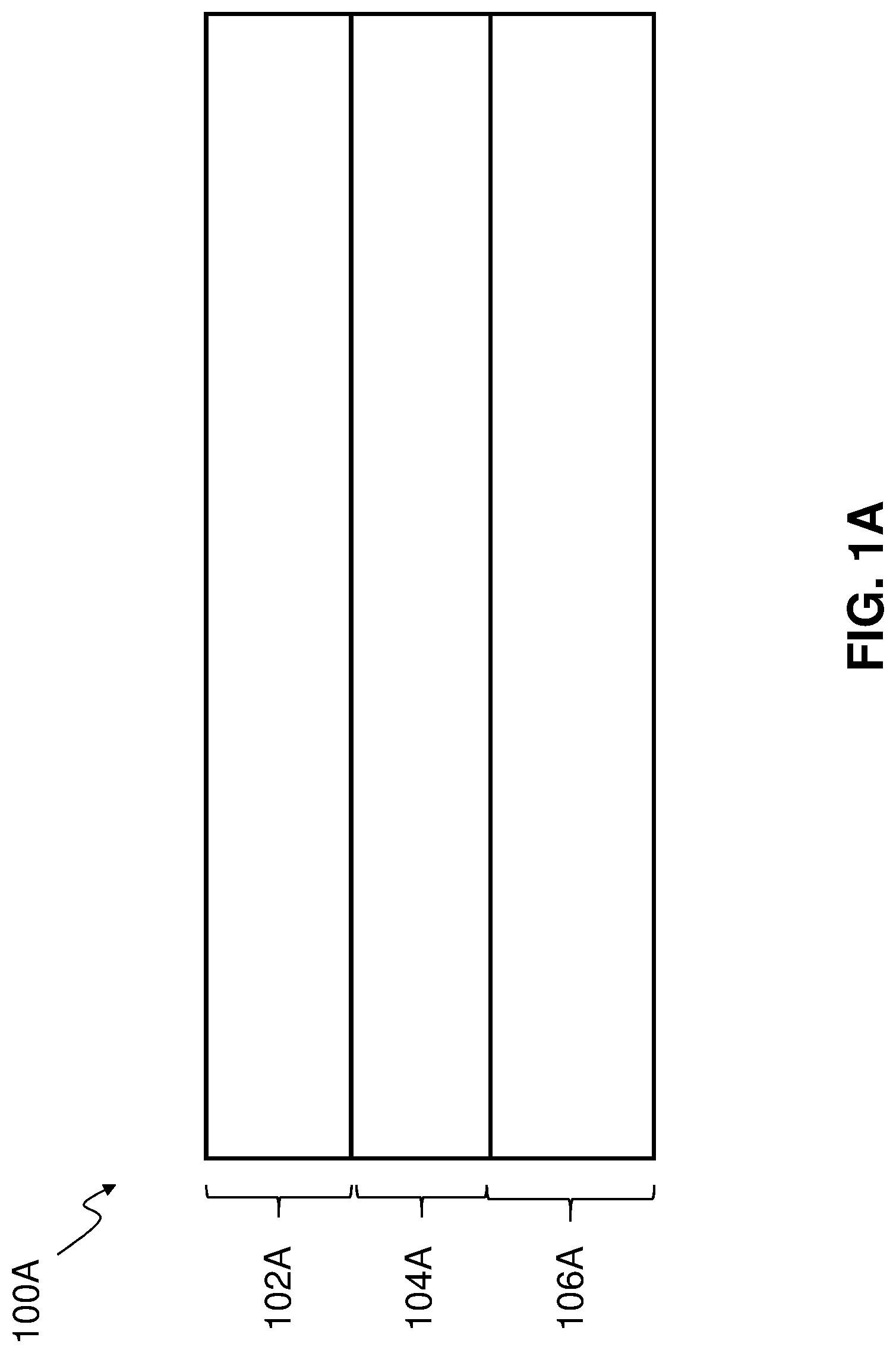
A shows stiffening element 100 A, according to some examples of the disclosed stiffening elements. As shown in A , stiffening element 100 A comprises: aluminum layer 102 A; glass composite layer 104 A adjacent to aluminum layer 102 A; and carbon composite layer 106 A adjacent to glass composite layer 104 A, and opposite to aluminum layer 102 A.
Glass composite layer 104 A may comprise one or more glass-fiber-reinforced thermoplastic prepreg plies. Carbon composite layer 106 A may comprise one or more carbon-fiber-reinforced thermoplastic prepreg plies.
As used herein, the term “prepreg” is an abbreviation for “pre-impregnated” composite fibers in which a matrix material, such as thermoplastic resin, is already present in the fiber reinforcement before molding occurs. Prepreg manufacturing techniques may be employed to manufacture composite parts for a variety of commercial uses including, for example, the manufacture of aircraft and/or spacecraft.
As used herein, the term “prepreg plies” includes both prepreg fabrics and prepreg tapes.
Stiffening element 100 A may provide, for example, reduced weight per given volume as compared to simple metal structures.
Aluminum layer 102 A may be configured to form the outer surface of stiffening element 100 A or an outer surface of stiffening element 100 A. Heat transfer via conduction, convection, and/or radiation near and/or at outer surfaces of a stiffening element (e.g., stiffening element 100 A) may limit potential heating damage to the stiffening element.
Stiffening element 100 A may comprise one or more integral current flowpaths. Aluminum layer 102 A may be configured to form at least part of the one or more integral current flowpaths.
As used herein, the term “integral current flowpath” means that the current flowpath is provided by stiffening element 100 A itself, and is not reliant upon other components, particularly other metallic components that might add weight to stiffening element 100 A (e.g., added copper foil or mesh). The EME conductivity also is not reliant upon, for example, ply-integrated interwoven wires (e.g., interwoven wire fabric), conductive nonwoven veils, conductive paints, or conductive surfacing films.
Aluminum layer 102 A, glass composite layer 104 A, and carbon composite layer 106 A may have the same or different thicknesses.
Aluminum layer 102 A may or may not have aluminum sublayers; glass composite layer 104 A may or may not have glass composite sublayers; and/or carbon composite layer 106 A may or may not have carbon composite sublayers.
As used herein, the term “aluminum” means the metallic element of atomic number 13 , including any isotopes thereof.
As used herein, the term “alloy” means a solid or liquid mixture of two or more metals, or of one or more metals with one or more nonmetallic elements, as in carbon steels.
As used herein, the term “layer” means a thickness of material laid on, formed on, or spread over a surface, body, or portion of a surface or body. A layer may cover the surface, body, or portion of the surface or body, or form an overlying part or segment of material that covers the surface, body, or portion of the surface or body. A layer may have constant or variable thickness.
As used herein, the term “aluminum layer” means a layer comprising aluminum. An aluminum layer may comprise, for example, pure aluminum, an aluminum alloy, or some other substance that comprises aluminum. The aluminum layer may comprise, for example, 1100 series aluminum (e.g., a commercially pure alloy of aluminum, such as 1100-O, 1100-H12, 1100-H14, 1100-H16, 1100-H18, 1100-H22, 1100-H24, 1100-H26, 1100-H28, 1100-H112, or 1100-H113 aluminum according to the International Alloy Designation System (“IADS”)). More generally, the aluminum layer may comprise, for example, a 1000 series aluminum alloy (e.g., aluminum alloy 1050, 1060, 1100, 1145, 1199, 1200, 1230, or 1350 according to IADS); a 2000 series aluminum alloy (e.g., aluminum alloy 2008, 2011, 2014, 2017, 2018, 2024, 2025, 2036, 2048, 2090, 2117, 2124, 2127, 2195, 2218, 2219, 2224, 2319, 2324, 2524, or 2618 according to IADS); a 3000 series aluminum alloy (e.g., aluminum alloy 3003, 3004, 3005, 3102, or 3105 according to IADS); a 5000 series aluminum alloy (e.g., aluminum alloy 5005, 5050, 5052, 5056, 5059, 5083, 5086, 5154, 5182, 5183, 5252, 5254, 5356, 5357, 5454, 5456, 5457, 5554, 5556, 5652, 5654, 5657, or 5754 according to IADS); a 6000 series aluminum alloy (e.g., aluminum alloy 6003, 6005, 6005A, 6009, 6010, 6013, 6016, 6053, 6060, 6061, 6062, 6063, 6066, 6070, 6082, 6101 (e.g., 6101-H111, 6101-T 64), 6105, 6111, 6151, 6162, 6201, 6205, 6253, 6262, 6351, 6463, or 6951 according to IADS); or a 7000 series aluminum alloy (e.g., aluminum alloy 7001, 7005, 7008, 7022, 7039, 7049, 7050, 7055, 7068, 7072, 7075, 7076, 7079, 7108, 7116, 7129, 7150, 7175, 7178, or 7475 according to IADS).
The pure aluminum, aluminum alloys, and/or other substances that comprise aluminum discussed above may be compatible with high-temperature processing (e.g., at temperatures required for thermoplastic processing or consolidation, such as ≥600° F., ≥650° F., ≥675° F., or ≥700° F., but less than the melting temperature of the pure aluminum, aluminum alloys, and/or other substances that comprise aluminum). For example, the pure aluminum, aluminum alloys, and/or other substances that comprise aluminum discussed above may exhibit low yield strength(s) (e.g., ≤7.2×10 3 pounds per square inch gage (“psig”), ≤5.8×10 3 psig, ≤5.1×10 3 psig, or ≤4.3×10 3 psig), helping to reduce residual thermal stresses in other layers during and/or after cooldown. Other factors may help to reduce residual thermal stresses in other layers during and/or after cooldown, such as the thickness of the pure aluminum, aluminum alloys, and/or other substances that comprise aluminum discussed above; the existence and number of sublayers of the pure aluminum, aluminum alloys, and/or other substances that comprise aluminum discussed above; and/or whether the pure aluminum, aluminum alloys, and/or other substances that comprise aluminum discussed above are in direct contact with a specific adjacent layer (e.g., a glass composite layer).
The pure aluminum, aluminum alloys, and/or other substances that comprise aluminum discussed above may exhibit high electrical conductivity (e.g., ≥45% per the International Annealed Copper Standard (“IACS”), ≥50% IACS, ≥55% IACS, or ≥57% IACS), helping to conduct electricity (e.g., power returns, steady state current returns, fault current returns) and/or to provide integral electromagnetic effects (“EME”) conductivity (e.g., protection from high-intensity radiated fields (“HIRF”), lightning-strike protection (“LSP”)), for example, in weight-efficient composite aircraft structures. Other factors may help to conduct electricity and/or to provide integral EME conductivity, such as the thickness of the pure aluminum, aluminum alloys, and/or other substances that comprise aluminum discussed above; the existence and number of sublayers of the pure aluminum, aluminum alloys, and/or other substances that comprise aluminum discussed above; and/or whether the pure aluminum, aluminum alloys, and/or other substances that comprise aluminum discussed above are in direct contact with an airframe electrical grounding system (e.g., metallic ground plane).
In addition to conductivity and resistivity, other material properties (e.g., corrosion resistance) and physical dimensions (e.g., cross-sectional area) may be important in ensuring that stiffening elements have the required level of current handling capability.
As used herein, the term “integral EME conductivity” means that the EME conductivity is provided by stiffening element 100 A itself, and is not reliant upon other components, particularly other metallic components that might add weight to stiffening element 100 A (e.g., added copper foil or mesh). The EME conductivity also is not reliant upon, for example, ply-integrated interwoven wires (e.g., interwoven wire fabric), conductive nonwoven veils, conductive paints, or conductive surfacing films.
The pure aluminum, aluminum alloys, and/or other substances that comprise aluminum discussed above may exhibit high thermal conductivity (e.g., ≥70 British thermal units/hour-foot-degree Fahrenheit (“BTU/hr-ft-° F.”), ≥85 BTU/hr-ft-° F., ≥100 BTU/hr-ft-° F., ≥115 BTU/hr-ft-° F., or ≥130 BTU/hr-ft-° F., helping to transfer, dissipate, and/or distribute thermal energy of the stiffening elements. Other factors may help to transfer, dissipate, and/or distribute thermal energy, such as the thickness of the pure aluminum, aluminum alloys, and/or other substances that comprise aluminum discussed above; the existence and number of sublayers of the pure aluminum, aluminum alloys, and/or other substances that comprise aluminum discussed above; and/or whether the pure aluminum, aluminum alloys, and/or other substances that comprise aluminum discussed above are in direct contact with a specific adjacent layer and/or an airframe electrical grounding system (e.g., metallic ground plane).
Surfaces of the aluminum layer may undergo surface preparation, such as alkaline degreasing, chromic acid anodizing or other anodizing processing, priming (e.g., with BR 127 corrosion-inhibiting primer), sol-gel, and/or pickling in chromic-sulfuric acid. The surfaces also may be roughened, for example, by abrasion. Such surface preparation may enhance bonding between the aluminum layer(s) and other layers.
The aluminum layer(s) may be depended on to provide current-carrying capacity for the stiffening element. Generally, in such cases, the number and/or thickness of the aluminum layer(s) are greater than when the aluminum layer(s) are not depended on to provide current-carrying capacity.
The aluminum layer(s) may be depended on to provide integral EME conductivity for the stiffening element. Generally, in such cases, the number and/or thickness of the aluminum layer(s) are greater than when the aluminum layer(s) are not depended on to provide integral EME conductivity.
The aluminum layer(s) may be depended on to provide thermal conductivity for the stiffening element. For example, the thermal conductivity may assist in a heat sink function via a CRN. Generally, in such cases, the number and/or thickness of the aluminum layer(s) are greater than when the aluminum layer(s) are not depended on to provide thermal conductivity.
The aluminum layer(s) may be depended on to provide significant structural support. Generally, in such cases, the number and/or thickness of the aluminum layer(s) are greater than when the aluminum layer(s) are not depended on to provide significant structural support. Whether or not depended on to provide significant structural support, thicknesses of the aluminum layer(s) may be, for example, ≥0.005 inches and ≤0.020 inches (e.g., 0.005 inches, 0.010 inches, 0.015 inches, or 0.020 inches). When depended on to provide significant structural support, thicknesses of the aluminum layer(s) may be even greater than 0.0020 inches.
As used herein, the term “composite” means a mixture or mechanical combination on a macroscale of two or more materials that are solid in the finished state, are mutually insoluble, and differ in chemical nature.
As used herein, the term “tenacity” means the strength per unit weight of a fiber, typically expressed in grams per denier.
As used herein, the term “fiber” means a fundamental form of solid (usually crystalline) characterized by relatively high tenacity and an extremely high ratio of length to diameter (e.g., several hundred or more to one). Semisynthetic fibers include inorganic substances extruded in fibrous form using, for example, carbon or glass. Synthetic fibers include substances extruded in fibrous form using, for example, high polymers.
As used herein, the term “glass” means a non-crystalline, amorphous solid. The glass may comprise, for example, a ceramic material comprising a mixture of silica, soda ash, and lime. The glass may comprise, for example, one or more of C-glass, E-glass, S-glass, or T-glass. The glass may be, for example, in the form of glass fibers (e.g., fiberglass). The glass may comprise, for example, S-2 glass (e.g., S-2 glass fibers).
The glass fibers may be woven or nonwoven (e.g., chopped, matted, or randomly oriented). The strength of the woven fibers may vary with the type of weave and/or the orientation of the woven fibers (e.g., if the woven fibers are oriented in parallel, the strength of the woven fibers as a group should be greater in directions parallel to that orientation). The type of weave may be, for example, a plain weave (e.g., 1×1), a twill weave (e.g., 2×2), a basket weave, a fish weave, a harness weave, a leno weave, a satin weave, or a unidirectional weave.
As used herein, the term “matrix” means a substance used to hold together strength members of a composite, where the substance is one of the two or more materials of the composite.
As used herein, the term “resin” means a semisolid or solid complex amorphous mix of organic compounds.
As used herein, the term “monomer” means a molecule or compound, usually comprising carbon, and of relatively low molecular weight and simple structure.
As used herein, the term “polymer” means a macromolecule formed by the chemical union of five or more identical monomers. A polymer may be, for example, inorganic or organic. An organic polymer may be, for example, natural or synthetic (e.g., man-made). A synthetic organic polymer may be, for example, thermoplastic or thermosetting.
As used herein, the term “high polymer” means an organic polymer having a molecular weight ≥5,000 grams/mole.
As used herein, the term “thermoplastic” means a high polymer, as defined above, that softens when exposed to heat and returns to its original condition when cooled to room temperature. A thermoplastic polymer may be, for example, amorphous or semi-crystalline. A thermoplastic polymer may comprise, for example, one or more of polyaryletherketone (“PAEK”), polyetherimide (“PEI”), or polyphenylene sulfide (“PPS”). A polyaryletherketone may comprise, for example, one or more of polyetherketone (“PEK”), polyetheretherketone (“PEEK”), polyetherketoneketone (“PEKK”), polyetheretherketoneketone (“PEEKK”), or polyetherketoneetherketoneketone (“PEKEKK”).
As used herein, the term “thermosetting polymer” means a high polymer, as defined above, that crosslinks upon the application of heat, and solidifies or “sets” irreversibly.
As used herein, the term “glass composite layer” means a layer comprising a composite that comprises glass. The glass may be, for example, in the form of glass fibers. The glass fibers in the glass composite layer may have no specific orientation (e.g., omnidirectional) or may be oriented in one or more directions (e.g., unidirectional, bidirectional, or multidirectional). The glass fibers may be aligned, continuous, and/or unidirectional.
A glass composite layer comprises, for example, a matrix. The matrix may comprise, for example, resin. The resin may comprise, for example, a thermoplastic polymer. The thermoplastic polymer may comprise, for example, one or more of PEEK (PEEK has a relatively high glass transition temperature (about 290° F.) and melting temperature (about 650° F.), allowing for high-temperature processing), PEKK (PEKK has a relatively high glass transition temperature (about 315° F.) and melting temperature (about 640° F.), allowing for high-temperature processing), or other thermoplastic polymers. A glass composite layer may comprise, for example, glass-fiber-reinforced polymer(s). A glass composite layer may comprise, for example, glass-fiber-reinforced thermoplastic polymer(s).
The thermoplastic resin of the one or more glass-fiber-reinforced thermoplastic prepreg plies provides binding for the glass fibers. The thermoplastic resin may exhibit a sufficiently high glass transition temperature, continuous service temperature, and/or crystallite melting point so as to allow the aluminum layer(s) (e.g., aluminum layer 102 A) to be softened for molding, shaping, and/or other processes associated with manufacture of the stiffening element(s).
The glass composite layer(s) may be depended on to provide significant structural support. Generally, in such cases, the number and/or thickness of the glass composite layer(s) are greater than when the glass composite layer(s) are not depended on to provide significant structural support.
Whether or not depended on to provide significant structural support, thicknesses of the glass composite layer(s) may be, for example, ≥0.0020 inches and ≤0.0080 inches (e.g., 0.0020 inches, 0.0025 inches, 0.0030 inches, 0.0035 inches, 0.0040 inches, 0.0045 inches, 0.0050 inches, 0.0055 inches, 0.0060 inches, 0.0065 inches, 0.0070 inches, 0.0075 inches, or 0.0080 inches). When depended on to provide significant structural support, thicknesses of the glass composite layer(s) may be even greater than 0.0080 inches.
Whether or not depended on to provide significant structural support, thicknesses of the sublayers of the glass composite layer(s) may be, for example, ≥0.0020 inches and ≤0.0040 inches (e.g., 0.0020 inches, 0.0025 inches, 0.0030 inches, 0.0035 inches, or 0.0040 inches). When depended on to provide significant structural support, thicknesses of the glass composite sublayer(s) may be even greater than 0.0040 inches.
As used herein, the term “adjacent” means “near or directly contacting.”
Resin of the glass composite layer may directly bond the aluminum layer and the glass composite layer (e.g., aluminum layer 102 A and glass composite layer 104 A). In such cases, glass composite layer 104 A may be adjacent to aluminum layer 102 A, and may directly contact aluminum layer 102 A.
An additional layer (not shown) may be between aluminum layer 102 A and glass composite layer 104 A. In such cases, glass composite layer 104 A may be adjacent to aluminum layer 102 A, but may not directly contact aluminum layer 102 A. The additional layer may improve the bonding of aluminum layer 102 A and glass composite layer 104 A. The additional layer may at least partially decouple effects (e.g., thermal contraction, thermal expansion, strains, or stresses) associated with the bonding of aluminum layer 102 A and glass composite layer 104 A.
The additional layer may be, for example, an adhesive layer. Care should be taken during selection of material(s) for such an additional layer because, for example, some adhesives comprise silver or other elements or compounds that may interact with aluminum layer 102 A and/or glass composite layer 104 A via one or more interaction mechanisms (e.g., galvanic corrosion).
As used herein, the term “carbon” means the nonmetallic element of atomic number 6 , including any isotopes thereof.
As used herein, the term “carbon composite layer” means a layer comprising a composite that comprises carbon. The carbon may be, for example, in the form of carbon fibers. The carbon fibers in the carbon composite layer may have no specific orientation (e.g., omnidirectional) or may be oriented in one or more directions (e.g., unidirectional, bidirectional, or multidirectional). The carbon fibers may be aligned, continuous, and/or unidirectional.
The carbon fibers may be woven. The strength of the woven fibers may vary with the type of weave and/or the orientation of the woven fibers (e.g., if the woven fibers are oriented in parallel, the strength of the woven fibers as a group should be greater in directions parallel to that orientation). The type of weave may be, for example, a plain weave (e.g., 1×1), a twill weave (e.g., 2×2), a basket weave, a fish weave, a harness weave, a leno weave, a satin weave, or a unidirectional weave.
A carbon composite layer comprises, for example, a matrix. The matrix may comprise, for example, resin. The resin may comprise, for example, a thermoplastic polymer. The thermoplastic polymer may comprise, for example, one or more of PEEK, PEKK, or other thermoplastic polymers. A carbon composite layer may comprise, for example, carbon-fiber-reinforced polymer(s). A carbon composite layer may comprise, for example, carbon-fiber-reinforced thermoplastic polymer(s).
The thermoplastic resin of the one or more carbon-fiber-reinforced thermoplastic prepreg plies provides binding for the carbon fibers. The thermoplastic resin may exhibit a sufficiently high glass transition temperature, continuous service temperature, and/or crystallite melting point so as to allow the aluminum layer(s) (e.g., aluminum layer 102 A) to be softened for molding, shaping, and/or other processes associated with manufacture of the stiffening element(s).
The carbon composite layer(s) may be depended on to provide significant structural support. Generally, in such cases, the number and/or thickness of the carbon composite layer(s) are greater than when the carbon composite layer(s) are not depended on to provide significant structural support.
Whether or not depended on to provide significant structural support, thicknesses of the carbon composite layer(s) may be, for example, ≥0.0400 inches and ≤0.1000 inches (e.g., 0.0400 inches, 0.0432 inches, 0.0440 inches, 0.0450 inches, 0.0500 inches, 0.0550 inches, 0.0600 inches, 0.0650 inches, 0.0700 inches, 0.0750 inches, 0.0800 inches, 0.0850 inches, 0.0900 inches, 0.0950 inches, 0.1000 inches). When depended on to provide significant structural support, thicknesses of the carbon composite layer(s) may be even greater than 0.0800 inches.
Whether or not depended on to provide significant structural support, thicknesses of the sublayers of the carbon composite layer(s) may be, for example, ≥0.0040 inches and ≤0.0080 inches (e.g., 0.0040 inches, 0.0044 inches, 0.0045 inches, 0.0050 inches, 0.0054 inches, 0.0055 inches, 0.0060 inches, 0.0065 inches, 0.0070 inches, 0.0075 inches, or 0.0080 inches). When depended on to provide significant structural support, thicknesses of the carbon composite sublayer(s) may be even greater than 0.0080 inches.
The one or more glass-fiber-reinforced thermoplastic prepreg plies may comprise first thermoplastic resin, the one or more carbon-fiber-reinforced thermoplastic prepreg plies may comprise second thermoplastic resin, and the first thermoplastic resin may be the same as the second thermoplastic resin. When the first thermoplastic resin is the same as the second thermoplastic resin, manufacture of the stiffening element(s) may be simplified, and the bonding between the one or more glass-fiber-reinforced thermoplastic prepreg plies and the one or more carbon-fiber-reinforced thermoplastic prepreg plies may be more uniform and/or more stable over time due, for example, to compatibility of the first and second thermoplastic resins.
The one or more glass-fiber-reinforced thermoplastic prepreg plies may comprise first thermoplastic resin, the one or more carbon-fiber-reinforced thermoplastic prepreg plies may comprise second thermoplastic resin, and the first thermoplastic resin may differ from the second thermoplastic resin. When the first thermoplastic resin differs from the second thermoplastic resin, more design options may be available during manufacture of the stiffening element(s), and the bonding between the one or more glass-fiber-reinforced thermoplastic prepreg plies and the one or more carbon-fiber-reinforced thermoplastic prepreg plies may be stronger initially and/or over time, particularly if the first and second thermoplastic resins are selected for mutual chemical compatibility.
The glass composite layer(s) may be configured to prevent interaction (e.g., direct) between the aluminum layer and the carbon composite layer (e.g., glass composite layer 104 A may be configured to prevent interaction between aluminum layer 102 A and carbon composite layer 106 A). The glass composite layer(s) may be configured to prevent galvanic corrosion due to interaction (e.g., direct or indirect) between the aluminum layer and the carbon composite layer (e.g., glass composite layer 104 A may be configured to prevent galvanic corrosion due to interaction between aluminum layer 102 A and carbon composite layer 106 A).
The glass composite layer(s) may be configured to reduce thermal stress, during cooldown (e.g., during a consolidation process), due to differences in thermal contraction between the aluminum layer and the carbon composite layer (e.g., glass composite layer 104 A may be configured to reduce thermal stress, during cooldown, due to differences in thermal contraction between aluminum layer 102 A and carbon composite layer 106 A), for example, by at least partially decoupling the effects of thermal contraction in the aluminum and carbon composite layers and/or through effects associated with orientation of glass fibers in the glass composite layer(s). The glass composite layer(s) may be configured to reduce residual thermal stress, after cooldown (e.g., after a consolidation process), due to differences in thermal contraction, during cooldown, between the aluminum layer and the carbon composite layer (e.g., glass composite layer 104 A may be configured to reduce residual thermal stress, after cooldown, due to differences in thermal contraction, during cooldown, between aluminum layer 102 A and carbon composite layer 106 A), for example, by at least partially decoupling the effects of thermal contraction in the aluminum and carbon composite layers and/or through effects associated with orientation of glass fibers in the glass composite layer(s).
One or more glass composite layers may be configured to reduce thermal stress, both during and after cooldown, functioning as a compliant layer or layers. This compliant functioning helps to avoid separation of adjacent layers due to the build-up of stress near, at, or across boundaries between the adjacent layers.
Resin of the glass composite layer may directly bond the glass composite layer and the carbon composite layer (e.g., glass composite layer 104 A and carbon composite layer 106 A). In such cases, glass composite layer 104 A may be adjacent to carbon composite layer 106 A, and may directly contact carbon composite layer 106 A.
Resin of the carbon composite layer may directly bond the glass composite layer and the carbon composite layer (e.g., glass composite layer 104 A and carbon composite layer 106 A). In such cases, glass composite layer 104 A may be adjacent to carbon composite layer 106 A, and may directly contact carbon composite layer 106 A.
Resins of the glass and carbon composite layers may directly bond the glass composite layer and the carbon composite layer (e.g., glass composite layer 104 A and carbon composite layer 106 A). In such cases, glass composite layer 104 A may be adjacent to carbon composite layer 106 A, and may directly contact carbon composite layer 106 A.
An additional layer (not shown) may be between glass composite layer 104 A and carbon composite layer 106 A. In such cases, glass composite layer 104 A may be adjacent to carbon composite layer 106 A, but may not directly contact carbon composite layer 106 A. The additional layer may improve the bonding of glass composite layer 104 A and carbon composite layer 106 A. The additional layer may at least partially decouple effects (e.g., thermal contraction, thermal expansion, strains, or stresses) associated with the bonding of glass composite layer 104 A and carbon composite layer 106 A.
The additional layer may be, for example, an adhesive layer. Care should be taken during selection of material(s) for such an additional layer because, for example, some adhesives comprise elements or compounds that may interact with glass composite layer 104 A and/or carbon composite layer 106 A via one or more interaction mechanisms.
One or more layers may be between a given aluminum layer and a given carbon composite layer. The one or more layers may comprise, for example, glass composite layer(s) and/or adhesive layer(s). The one or more layers may be configured to prevent interaction (e.g., direct) between the aluminum layer(s) and the carbon composite layer(s) (e.g., configured to prevent interaction between aluminum layer 102 A and carbon composite layer 106 A). The one or more layers may be configured to prevent galvanic corrosion due to interaction (e.g., direct or indirect) between the aluminum layer(s) and the carbon composite layer(s) (e.g., configured to prevent galvanic corrosion due to interaction between aluminum layer 102 A and carbon composite layer 106 A).
B shows stiffening element 100 B, according to some examples of the disclosed stiffening elements. As shown in B , stiffening element 100 B comprises: aluminum layer 102 B; glass composite layer 104 B adjacent to aluminum layer 102 B; and carbon composite layer 106 B adjacent to glass composite layer 104 B, and opposite to aluminum layer 102 B.
Glass composite layer 104 B may comprise one or more glass-fiber-reinforced thermoplastic prepreg plies. Carbon composite layer 106 B may comprise one or more carbon-fiber-reinforced thermoplastic prepreg plies.
Aluminum layer 102 B may comprise a plurality of aluminum sublayers 102 B 1 , 102 B 2 , 102 B 3 , 102 B 4 (e.g., 102 B 1 , 102 B 2 , . . . , 102 Bn). The number (n) of aluminum sublayers may be, for example, 2, 3, 4, 5, 6, or more sublayers.
Aluminum layer 102 B, glass composite layer 104 B, and carbon composite layer 106 B may have the same or different thicknesses. Similarly, plurality of aluminum sublayers 102 B 1 , 102 B 2 , 102 B 3 , 102 B 4 may have the same or different thicknesses.
Aluminum layer 102 B (e.g., aluminum sublayer 102 B 1 ) may be configured to form the outer surface of stiffening element 100 B or an outer surface of stiffening element 100 B.
Stiffening element 100 B may comprise one or more integral current flowpaths. Aluminum layer 102 B (e.g., one or more of aluminum sublayers 102 B 1 , 102 B 2 , 102 B 3 , or 102 B 4 ) may be configured to form at least part of the one or more integral current flowpaths.
C shows stiffening element 100 C, according to some examples of the disclosed stiffening elements. As shown in C , stiffening element 100 C comprises: aluminum layer 102 C; glass composite layer 104 C adjacent to aluminum layer 102 C; and carbon composite layer 106 C adjacent to glass composite layer 104 C, and opposite to aluminum layer 102 C.
Glass composite layer 104 C may comprise one or more glass-fiber-reinforced thermoplastic prepreg plies. Carbon composite layer 106 C may comprise one or more carbon-fiber-reinforced thermoplastic prepreg plies.
Glass composite layer 104 C may comprise a plurality of glass composite sublayers 104 C 1 , 104 C 2 , 104 C 3 , 104 C 4 (e.g., 104 C 1 , 104 C 2 , . . . , 104 Cn). The number (n) of glass composite sublayers may be, for example, 2, 3, 4, 5, 6, 7, 8, 9, 10, 11, 12, or more sublayers.
Aluminum layer 102 C, glass composite layer 104 C, and carbon composite layer 106 C may have the same or different thicknesses. Similarly, plurality of glass composite sublayers 104 C 1 , 104 C 2 , 104 C 3 , 104 C 4 may have the same or different thicknesses.
Aluminum layer 102 C may be configured to form the outer surface of stiffening element 100 C or an outer surface of stiffening element 100 C.
Stiffening element 100 C may comprise one or more integral current flowpaths. Aluminum layer 102 C may be configured to form at least part of the one or more integral current flowpaths.
D shows stiffening element 100 D, according to some examples of the disclosed stiffening elements. As shown in D , stiffening element 100 D comprises: aluminum layer 102 D; glass composite layer 104 D adjacent to aluminum layer 102 D; and carbon composite layer 106 D adjacent to glass composite layer 104 D, and opposite to aluminum layer 102 D.
Glass composite layer 104 D may comprise one or more glass-fiber-reinforced thermoplastic prepreg plies. Carbon composite layer 106 D may comprise one or more carbon-fiber-reinforced thermoplastic prepreg plies.
Carbon composite layer 106 D may comprise a plurality of carbon composite sublayers 106 D 1 , 106 D 2 , 106 D 3 , 106 D 4 (e.g., 106 D 1 , 106 D 2 , . . . , 106 Dn). The number (n) of carbon composite sublayers may be, for example, 2, 3, 4, 5, 6, 7, 8, 9, 10, 11, 12, 13, 14, 15, 16, 17, 18, 19, 20, 21, 22, 23, 24, 25, 26, 27, 28, 29, 30, 31, 32, or more sublayers (e.g., 8, 16, 24, 32, 40, or 64 sublayers).
Aluminum layer 102 D, glass composite layer 104 D, and carbon composite layer 106 D may have the same or different thicknesses. Similarly, plurality of carbon composite sublayers 106 D 1 , 106 D 2 , 106 D 3 , 106 D 4 may have the same or different thicknesses.
Aluminum layer 102 D may be configured to form the outer surface of stiffening element 100 D or an outer surface of stiffening element 100 D.
Stiffening element 100 D may comprise one or more integral current flowpaths. Aluminum layer 102 D may be configured to form at least part of the one or more integral current flowpaths.
E shows stiffening element 100 E, according to some examples of the disclosed stiffening elements. As shown in E , stiffening element 100 E comprises: aluminum layer 102 E; glass composite layer 104 E adjacent to aluminum layer 102 E; and carbon composite layer 106 E adjacent to glass composite layer 104 E, and opposite to aluminum layer 102 E.
Glass composite layer 104 E may comprise one or more glass-fiber-reinforced thermoplastic prepreg plies. Carbon composite layer 106 E may comprise one or more carbon-fiber-reinforced thermoplastic prepreg plies.
Aluminum layer 102 E may comprise a plurality of aluminum sublayers 102 E 1 , 102 E 2 (e.g., 102 E 1 , 102 E 2 , . . . , 102 En). The number (n) of aluminum sublayers may be, for example, 2, 3, 4, 5, 6, or more sublayers. Glass composite layer 104 E may comprise a plurality of glass composite sublayers 104 E 1 , 104 E 2 , 104 E 3 , 104 E 4 (e.g., 104 E 1 , 104 E 2 , . . . , 104 Eo). The number (o) of glass composite sublayers may be, for example, 2, 3, 4, 5, 6, 7, 8, 9, 10, 11, 12, or more sublayers. Carbon composite layer 106 E may comprise a plurality of carbon composite sublayers 106 E 1 , 106 E 2 , 106 E 3 (e.g., 106 E 1 , 106 E 2 , . . . , 106 Ep). The number (p) of carbon composite sublayers may be, for example, 2, 3, 4, 5, 6, 7, 8, 9, 10, 11, 12, 13, 14, 15, 16, 17, 18, 19, 20, 21, 22, 23, 24, 25, 26, 27, 28, 29, 30, 31, 32, or more sublayers (e.g., 8, 16, 24, 32, 40, or 64 sublayers).
The number of aluminum sublayers may be the same as or differ from the number of glass composite sublayers. The number of aluminum sublayers may be the same as or differ from the number of carbon composite sublayers. The number of glass composite sublayers may be the same as or differ from the number of carbon composite sublayers.
Aluminum layer 102 E, glass composite layer 104 E, and carbon composite layer 106 E may have the same or different thicknesses. Plurality of plurality of aluminum sublayers 102 E 1 , 102 E 2 may have the same or different thicknesses. Plurality of glass composite sublayers 104 E 1 , 104 E 2 , 104 E 3 , 104 E 4 may have the same or different thicknesses. Plurality of carbon composite sublayers 106 E 1 , 106 E 2 , 106 E 3 may have the same or different thicknesses.
Aluminum layer 102 E (e.g., aluminum sublayer 102 E 1 ) may be configured to form the outer surface of stiffening element 100 E or an outer surface of stiffening element 100 E.
Stiffening element 100 E may comprise one or more integral current flowpaths. Aluminum layer 102 E (e.g., one or both of aluminum sublayers 102 E 1 or 102 E 2 ) may be configured to form at least part of the one or more integral current flowpaths.
The glass composite layer (e.g., glass composite layer 104 A, 104 B, 104 C, 104 D, 104 E) may comprise first thermoplastic resin. The first thermoplastic resin may comprise PEEK. The first thermoplastic resin may comprise PEKK. the first thermoplastic resin may comprise one or more of PAEK, PEI, or PPS. The first thermoplastic resin may comprise, for example, one or more of PAEK, PEEK, PEEKK, PEI, PEK, PEKEKK, PEKK, or PPS. The carbon composite layer (e.g., carbon composite layer 106 A, 106 B, 106 C, 106 D, 106 E) may comprise second thermoplastic resin. The second thermoplastic resin may comprise PEEK. The second thermoplastic resin may comprise PEKK. The second thermoplastic resin may comprise one or more of PAEK, PEI, or PPS. The second thermoplastic resin may comprise, for example, one or more of PAEK, PEEK, PEEKK, PEI, PEK, PEKEKK, PEKK, or PPS. The first thermoplastic resin may be the same as the second thermoplastic resin. The first thermoplastic resin may differ from the second thermoplastic resin.
A shows stiffening element 200 A, according to some examples of the disclosed stiffening elements. As shown in A , stiffening element 200 A comprises: first aluminum layer 202 A; first glass composite layer 204 A adjacent to first aluminum layer 202 A; first carbon composite layer 206 A adjacent to first glass composite layer 204 A, and opposite to first aluminum layer 202 A; and second glass composite layer 208 A adjacent to first carbon composite layer 206 A, and opposite to first glass composite layer 204 A.
First aluminum layer 202 A may be configured to form the outer surface of stiffening element 200 A or an outer surface of stiffening element 200 A.
Stiffening element 200 A may comprise one or more integral current flowpaths. Aluminum layer 202 A may be configured to form at least part of the one or more integral current flowpaths.
First aluminum layer 202 A may comprise a plurality of first aluminum sublayers (not shown). The number of first aluminum sublayers may be, for example, 2, 3, 4, 5, 6, or more sublayers. First glass composite layer 204 A may comprise a plurality of first glass composite sublayers (not shown). The number of first glass composite sublayers may be, for example, 2, 3, 4, 5, 6, 7, 8, 9, 10, 11, 12, or more sublayers. Each or all of the first glass composite sublayers may comprise one or more glass-fiber-reinforced thermoplastic prepreg plies. First carbon composite layer 206 A may comprise a plurality of first carbon composite sublayers (not shown). The number of first carbon composite sublayers may be, for example, 2, 3, 4, 5, 6, 7, 8, 9, 10, 11, 12, 13, 14, 15, 16, 17, 18, 19, 20, 21, 22, 23, 24, 25, 26, 27, 28, 29, 30, 31, 32, or more sublayers (e.g., 8, 16, 24, 32, 40, or 64 sublayers). Each or all of the first carbon composite sublayers may comprise one or more carbon-fiber-reinforced thermoplastic prepreg plies.
Second glass composite layer 208 A may comprise a plurality of second glass composite sublayers (not shown). The number of second glass composite sublayers may be, for example, 2, 3, 4, 5, 6, 7, 8, 9, 10, 11, 12, or more sublayers. Each or all of the sublayers may comprise one or more glass-fiber-reinforced thermoplastic prepreg plies.
First glass composite layer 204 A may comprise one or more first glass-fiber-reinforced thermoplastic prepreg plies which, in turn, may comprise first thermoplastic resin. First carbon composite layer 206 A may comprise one or more first carbon-fiber-reinforced thermoplastic prepreg plies which, in turn, may comprise second thermoplastic resin. Second glass composite layer 208 A may comprise one or more second glass-fiber-reinforced thermoplastic prepreg plies which, in turn, may comprise third thermoplastic resin. The first thermoplastic resin may be the same as or differ from the second thermoplastic resin. The first thermoplastic resin may be the same as or differ from the third thermoplastic resin. The second thermoplastic resin may be the same as or differ from the third thermoplastic resin.
The first thermoplastic resin may comprise PEEK. The first thermoplastic resin may comprise PEKK. The first thermoplastic resin may comprise one or more of PAEK, PEI, or PPS. The first thermoplastic resin may comprise, for example, one or more of PAEK, PEEK, PEEKK, PEI, PEK, PEKEKK, PEKK, or PPS. The second thermoplastic resin may comprise PEEK. The second thermoplastic resin may comprise PEKK. The second thermoplastic resin may comprise one or more of PAEK, PEI, or PPS. The second thermoplastic resin may comprise, for example, one or more of PAEK, PEEK, PEEKK, PEI, PEK, PEKEKK, PEKK, or PPS. The third thermoplastic resin may comprise PEEK. The third thermoplastic resin may comprise PEKK. The third thermoplastic resin may comprise one or more of PAEK, PEI, or PPS. The third thermoplastic resin may comprise, for example, one or more of PAEK, PEEK, PEEKK, PEI, PEK, PEKEKK, PEKK, or PPS.
B shows stiffening element 200 B, according to some examples of the disclosed stiffening elements. As shown in B , stiffening element 200 B comprises: first aluminum layer 202 B; first glass composite layer 204 B adjacent to first aluminum layer 202 B; first carbon composite layer 206 B adjacent to first glass composite layer 204 B, and opposite to first aluminum layer 202 B; second glass composite layer 208 B adjacent to first carbon composite layer 206 B, and opposite to first glass composite layer 204 B; and second aluminum layer 210 B adjacent to second glass composite layer 208 B, and opposite to first carbon composite layer 206 B.
First glass composite layer 204 B may comprise one or more glass-fiber-reinforced thermoplastic prepreg plies. First carbon composite layer 206 B may comprise one or more carbon-fiber-reinforced thermoplastic prepreg plies. Second glass composite layer 208 B may comprise one or more glass-fiber-reinforced thermoplastic prepreg plies.
First aluminum layer 202 B may be configured to form the outer surface of stiffening element 200 B or an outer surface of stiffening element 200 B. Second aluminum layer 210 B may be configured to form the outer surface of stiffening element 200 B or an outer surface of stiffening element 200 B. First aluminum layer 202 B may be configured to form a first outer surface of stiffening element 200 B, while second aluminum layer 210 B may be configured to form a second outer surface of stiffening element 200 B. The first outer surface of stiffening element 200 B may be substantially parallel to the second outer surface of stiffening element 200 B.
Stiffening element 200 B may comprise one or more integral current flowpaths. First aluminum layer 202 B may be configured to form at least part of the one or more integral current flowpaths. Second aluminum layer 210 B may be configured to form at least part of the one or more integral current flowpaths.
First aluminum layer 202 B may be configured to form a first flowpath of the one or more integral current flowpaths. Second aluminum layer 210 B may be configured to form a second flowpath of the one or more integral current flowpaths. The first flowpath may differ from the second flowpath (e.g., independent from each other). The first and second flowpaths may be part of a same integral current flowpath.
Current flow in the first flowpath may be substantially parallel to current flow in the second flowpath. Current flow in the first flowpath may be substantially in a same direction as current flow in the second flowpath. Current flow in the first flowpath may be substantially in an opposite direction from current flow in the second flowpath. Current flow in the first flowpath may be substantially parallel to and in a same direction as current flow in the second flowpath. Current flow in the first flowpath may be substantially parallel to but in an opposite direction from current flow in the second flowpath.
First aluminum layer 202 B may comprise a plurality of first aluminum sublayers (not shown). The number of first aluminum sublayers may be, for example, 2, 3, 4, 5, 6, or more sublayers. First glass composite layer 204 B may comprise a plurality of first glass composite sublayers (not shown). The number of first glass composite sublayers may be, for example, 2, 3, 4, 5, 6, 7, 8, 9, 10, 11, 12, or more sublayers. Each or all of the first glass composite sublayers may comprise one or more glass-fiber-reinforced thermoplastic prepreg plies. First carbon composite layer 206 B may comprise a plurality of first carbon composite sublayers (not shown). The number of first carbon composite sublayers may be, for example, 2, 3, 4, 5, 6, 7, 8, 9, 10, 11, 12, 13, 14, 15, 16, 17, 18, 19, 20, 21, 22, 23, 24, 25, 26, 27, 28, 29, 30, 31, 32, or more sublayers (e.g., 8, 16, 24, 32, 40, or 64 sublayers). Each or all of the first carbon composite sublayers may comprise one or more carbon-fiber-reinforced thermoplastic prepreg plies.
Second aluminum layer 210 B may comprise a plurality of second aluminum sublayers (not shown). The number of second aluminum sublayers may be, for example, 2, 3, 4, 5, 6, or more sublayers.
First aluminum layer 202 B and second aluminum layer 210 B may comprise the same aluminum alloy. First aluminum layer 202 B and second aluminum layer 210 B may comprise different aluminum alloys.
C shows stiffening element 200 C, according to some examples of the disclosed stiffening elements. As shown in C , stiffening element 200 C comprises: first aluminum layer 202 C; first glass composite layer 204 C adjacent to first aluminum layer 202 C; first carbon composite layer 206 C adjacent to first glass composite layer 204 C, and opposite to first aluminum layer 202 C; second glass composite layer 208 C adjacent to first carbon composite layer 206 C, and opposite to first glass composite layer 204 C; and second carbon composite layer 212 C adjacent to second glass composite layer 208 C, and opposite to first carbon composite layer 206 C.
First aluminum layer 202 C may comprise a plurality of first aluminum sublayers (not shown). The number of first aluminum sublayers may be, for example, 2, 3, 4, 5, 6, or more sublayers. First glass composite layer 204 C may comprise a plurality of first glass composite sublayers (not shown). The number of first glass composite sublayers may be, for example, 2, 3, 4, 5, 6, 7, 8, 9, 10, 11, 12, or more sublayers. Each or all of the first glass composite sublayers may comprise one or more glass-fiber-reinforced thermoplastic prepreg plies. First carbon composite layer 206 C may comprise a plurality of first carbon composite sublayers (not shown). The number of first carbon composite sublayers may be, for example, 2, 3, 4, 5, 6, 7, 8, 9, 10, 11, 12, 13, 14, 15, 16, 17, 18, 19, 20, 21, 22, 23, 24, 25, 26, 27, 28, 29, 30, 31, 32, or more sublayers (e.g., 8, 16, 24, 32, 40, or 64 sublayers). Each or all of the first carbon composite sublayers may comprise one or more carbon-fiber-reinforced thermoplastic prepreg plies.
Second carbon composite layer 212 C may comprise a plurality of second carbon composite sublayers (not shown). The number of second carbon composite sublayers may be, for example, 2, 3, 4, 5, 6, 7, 8, 9, 10, 11, 12, 13, 14, 15, 16, 17, 18, 19, 20, 21, 22, 23, 24, 25, 26, 27, 28, 29, 30, 31, 32, or more sublayers (e.g., 8, 16, 24, 32, 40, or 64 sublayers). Each or all of the sublayers may comprise one or more carbon-fiber-reinforced thermoplastic prepreg plies.
First glass composite layer 204 C may comprise one or more first glass-fiber-reinforced thermoplastic prepreg plies which, in turn, may comprise first thermoplastic resin. First carbon composite layer 206 C may comprise one or more first carbon-fiber-reinforced thermoplastic prepreg plies which, in turn, may comprise second thermoplastic resin. Second glass composite layer 208 C may comprise one or more second glass-fiber-reinforced thermoplastic prepreg plies which, in turn, may comprise third thermoplastic resin. Second carbon composite layer 212 C may comprise one or more second carbon-fiber-reinforced thermoplastic prepreg plies which, in turn, may comprise fourth thermoplastic resin. The first thermoplastic resin may be the same as or differ from the second thermoplastic resin. The first thermoplastic resin may be the same as or differ from the third thermoplastic resin. The first thermoplastic resin may be the same as or differ from the fourth thermoplastic resin. The second thermoplastic resin may be the same as or differ from the third thermoplastic resin. The second thermoplastic resin may be the same as or differ from the fourth thermoplastic resin. The third thermoplastic resin may be the same as or differ from the fourth thermoplastic resin.
The first thermoplastic resin may comprise PEEK. The first thermoplastic resin may comprise PEKK. The first thermoplastic resin may comprise one or more of PAEK, PEI, or PPS. The first thermoplastic resin may comprise, for example, one or more of PAEK, PEEK, PEEKK, PEI, PEK, PEKEKK, PEKK, or PPS. The second thermoplastic resin may comprise PEEK. The second thermoplastic resin may comprise PEKK. The second thermoplastic resin may comprise one or more of PAEK, PEI, or PPS. The second thermoplastic resin may comprise, for example, one or more of PAEK, PEEK, PEEKK, PEI, PEK, PEKEKK, PEKK, or PPS. The third thermoplastic resin may comprise PEEK. The third thermoplastic resin may comprise PEKK. The third thermoplastic resin may comprise one or more of PAEK, PEI, or PPS. The third thermoplastic resin may comprise, for example, one or more of PAEK, PEEK, PEEKK, PEI, PEK, PEKEKK, PEKK, or PPS. The fourth thermoplastic resin may comprise PEEK. The fourth thermoplastic resin may comprise PEKK. The fourth thermoplastic resin may comprise one or more of PAEK, PEI, or PPS. The fourth thermoplastic resin may comprise, for example, one or more of PAEK, PEEK, PEEKK, PEI, PEK, PEKEKK, PEKK, or PPS.
D shows stiffening element 200 D, according to some examples of the disclosed stiffening elements. As shown in D , stiffening element 200 D may comprise: first aluminum layer 202 D; first glass composite layer 204 D adjacent to first aluminum layer 202 D; first carbon composite layer 206 D adjacent to first glass composite layer 204 D, and opposite to first aluminum layer 202 D; second glass composite layer 208 D adjacent to first carbon composite layer 206 D, and opposite to first glass composite layer 204 D; second aluminum layer 210 D adjacent to second glass composite layer 208 D, and opposite to first carbon composite layer 206 D; third glass composite layer 214 D adjacent to second aluminum layer 210 D, and opposite to second glass composite layer 208 D; second carbon composite layer 216 D adjacent to third glass composite layer 214 D, and opposite to second aluminum layer 210 D; fourth glass composite layer 218 D adjacent to second carbon composite layer 216 D, and opposite to third glass composite layer 214 D; and third aluminum layer 220 D adjacent to fourth glass composite layer 218 D, and opposite to second carbon composite layer 216 D.
Each of the aluminum layers may comprise a plurality of aluminum sublayers (not shown). The number of aluminum sublayers may be, for example, 2, 3, 4, 5, 6, or more sublayers. Each of the glass composite layers may comprise a plurality of glass composite sublayers (not shown). The number of glass composite sublayers may be, for example, 2, 3, 4, 5, 6, 7, 8, 9, 10, 11, 12, or more sublayers. Each of the carbon composite layers may comprise a plurality of carbon composite sublayers (not shown). The number of carbon composite sublayers may be, for example, 2, 3, 4, 5, 6, 7, 8, 9, 10, 11, 12, 13, 14, 15, 16, 17, 18, 19, 20, 21, 22, 23, 24, 25, 26, 27, 28, 29, 30, 31, 32, or more sublayers (e.g., 8, 16, 24, 32, 40, or 64 sublayers).
First aluminum layer 202 D may be configured to form the outer surface of stiffening element 200 D or an outer surface of stiffening element 200 D. Third aluminum layer 220 D may be configured to form the outer surface of stiffening element 200 D or an outer surface of stiffening element 200 D. First aluminum layer 202 D may be configured to form a first outer surface of stiffening element 200 D, while third aluminum layer 220 D may be configured to form a second outer surface of stiffening element 200 D. The first outer surface of stiffening element 200 D may be substantially parallel to the second outer surface of stiffening element 200 D.
Stiffening element 200 D may comprise one or more integral current flowpaths. First aluminum layer 202 D may be configured to form at least part of the one or more integral current flowpaths. Second aluminum layer 210 D may be configured to form at least part of the one or more integral current flowpaths. Third aluminum layer 220 D may be configured to form at least part of the one or more integral current flowpaths.
First aluminum layer 202 D may be configured to form a first flowpath of the one or more integral current flowpaths. Third aluminum layer 220 D may be configured to form a second flowpath of the one or more integral current flowpaths. The first flowpath may differ from the second flowpath (e.g., independent from each other). The first and second flowpaths may be part of a same integral current flowpath.
Current flow in the first flowpath may be substantially parallel to current flow in the second flowpath. Current flow in the first flowpath may be substantially in a same direction as current flow in the second flowpath. Current flow in the first flowpath may be substantially in an opposite direction from current flow in the second flowpath. Current flow in the first flowpath may be substantially parallel to and in a same direction as current flow in the second flowpath. Current flow in the first flowpath may be substantially parallel to but in an opposite direction from current flow in the second flowpath.
First aluminum layer 202 D may be configured to form a first flowpath of the one or more integral current flowpaths. Second aluminum layer 210 D may be configured to form a second flowpath of the one or more integral current flowpaths. Third aluminum layer 220 D may be configured to form a third flowpath of the one or more integral current flowpaths. The first flowpath may differ from the second flowpath (e.g., independent from each other), the first flowpath may differ from the third flowpath (e.g., independent from each other), and second flowpath may differ from the third flowpath (e.g., independent from each other).
Current flow in any of the first, second, or third flowpaths may be substantially parallel to current flow in either of the other two flowpaths. Current flow in any of the first, second, or third flowpaths may be substantially in a same direction as current flow in either of the other two flowpaths. Current flow in any of the first, second, or third flowpaths may be substantially in an opposite direction from current flow in either of the other two flowpaths. Current flow in any of the first, second, or third flowpaths may be substantially parallel to and in a same direction as current flow in in either of the other two flowpaths. Current flow in any of the first, second, or third flowpaths may be substantially parallel to but in an opposite direction from current flow in either of the other two flowpaths.
First aluminum layer 202 D and second aluminum layer 210 D may comprise the same aluminum alloy. First aluminum layer 202 D and third aluminum layer 220 D may comprise the same aluminum alloy. Second aluminum layer 210 D and third aluminum layer 220 D may comprise the same aluminum alloy. First aluminum layer 202 D, second aluminum layer 210 D, and third aluminum layer 220 D may comprise the same aluminum alloy.
First aluminum layer 202 D and second aluminum layer 210 D may comprise different aluminum alloys. First aluminum layer 202 D and third aluminum layer 220 D may comprise different aluminum alloys. Second aluminum layer 210 D and third aluminum layer 220 D may comprise different aluminum alloys. First aluminum layer 202 D, second aluminum layer 210 D, and third aluminum layer 220 D each may comprise different aluminum alloys.
Each or all of the glass composite layers may comprise one or more glass-fiber-reinforced thermoplastic prepreg plies which, in turn, may comprise first thermoplastic resin. The first thermoplastic resin may comprise PEEK. The first thermoplastic resin may comprise PEKK. The first thermoplastic resin may comprise one or more of PAEK, PEI, or PPS. The first thermoplastic resin may comprise one or more of PAEK, PEEK, PEEKK, PEI, PEK, PEKEKK, PEKK, or PPS. The first thermoplastic resin may be the same as or differ from the thermoplastic resin in any other glass or carbon composite layer(s).
Each or all of the carbon composite layers may comprise one or more carbon-fiber-reinforced thermoplastic prepreg plies which, in turn, may comprise second thermoplastic resin. In each or all of the carbon composite layers, the second thermoplastic resin may comprise PEEK. In each or all of the carbon composite layers, the second thermoplastic resin may comprise PEKK. In each or all of the carbon composite layers, the second thermoplastic resin may comprise one or more of PAEK, PEI, or PPS. In each or all of the carbon composite layers, the second thermoplastic resin may comprise one or more of PAEK, PEEK, PEEKK, PEI, PEK, PEKEKK, PEKK, or PPS. In each of the carbon composite layers, the second thermoplastic resin may be the same as or differ from the thermoplastic resin in any other carbon or glass composite layer(s).
E shows stiffening element 200 E, according to some examples of the disclosed stiffening elements. As shown in E , stiffening element 200 E may comprise: first aluminum layer 202 E; first glass composite layer 204 E adjacent to first aluminum layer 202 E; first carbon composite layer 206 E adjacent to first glass composite layer 204 E, and opposite to first aluminum layer 202 E; second glass composite layer 208 E adjacent to first carbon composite layer 206 E, and opposite to first glass composite layer 204 E; second carbon composite layer 212 E adjacent to second glass composite layer 208 E, and opposite to first carbon composite layer 206 E; third glass composite layer 222 E adjacent to second carbon composite layer 212 E, and opposite to second glass composite layer 208 E; third carbon composite layer 224 E adjacent to third glass composite layer 222 E, and opposite to second carbon composite layer 212 E; and/or fourth glass composite layer 226 E adjacent to third carbon composite layer 224 E, and opposite to third glass composite layer 222 E.
First aluminum layer 202 E may comprise a plurality of first aluminum sublayers (not shown). The number of first aluminum sublayers may be, for example, 2, 3, 4, 5, 6, or more sublayers. Each of the glass composite layers may comprise a plurality of glass composite sublayers (not shown). The number of glass composite sublayers may be, for example, 2, 3, 4, 5, 6, 7, 8, 9, 10, 11, 12, or more sublayers. Each of the carbon composite layers may comprise a plurality of carbon composite sublayers (not shown). The number of carbon composite sublayers may be, for example, 2, 3, 4, 5, 6, 7, 8, 9, 10, 11, 12, 13, 14, 15, 16, 17, 18, 19, 20, 21, 22, 23, 24, 25, 26, 27, 28, 29, 30, 31, 32, or more sublayers (e.g., 8, 16, 24, 32, 40, or 64 sublayers).
Each or all of the glass composite layers may comprise one or more glass-fiber-reinforced thermoplastic prepreg plies which, in turn, may comprise first thermoplastic resin. In each or all of the glass composite layers, the first thermoplastic resin may comprise PEEK. In each or all of the glass composite layers, the first thermoplastic resin may comprise PEKK. In each or all of the glass composite layers, the first thermoplastic resin may comprise one or more of PAEK, PEI, or PPS. In each or all of the glass composite layers, the first thermoplastic resin may comprise one or more of PAEK, PEEK, PEEKK, PEI, PEK, PEKEKK, PEKK, or PPS. In each of the glass composite layers, the first thermoplastic resin may be the same as or differ from the thermoplastic resin in any other glass or carbon composite layer(s).
Each or all of the carbon composite layers may comprise one or more carbon-fiber-reinforced thermoplastic prepreg plies which, in turn, may comprise second thermoplastic resin. In each or all of the carbon composite layers, the second thermoplastic resin may comprise PEEK. In each or all of the carbon composite layers, the second thermoplastic resin may comprise PEKK. In each or all of the carbon composite layers, the second thermoplastic resin may comprise one or more of PAEK, PEI, or PPS. In each or all of the carbon composite layers, the second thermoplastic resin may comprise one or more of PAEK, PEEK, PEEKK, PEI, PEK, PEKEKK, PEKK, or PPS. In each of the carbon composite layers, the second thermoplastic resin may be the same as or differ from the thermoplastic resin in any other carbon or glass composite layer(s).
A shows laying up a first layer on a mold tool (e.g., a mandrel), according to some examples of the disclosed stiffening elements. As shown in A , first layer 302 may be laid up on mold tool 300 . Mold tool 300 may be of substantially any shape. First layer 302 may comprise, for example, an aluminum layer, a glass composite layer, or a carbon composite layer. To facilitate subsequent removal of a stiffening element from mold tool 300 , a parting film or similar may be used between mold tool 300 and first layer 302 . First layer 302 may comprise two or more sublayers (not shown).
B shows laying up a second layer on the first layer of A , according to some examples of the disclosed stiffening elements. As shown in B , second layer 304 may be laid up on first layer 302 to form a first portion of stack 318 (see D ). Second layer 304 may comprise, for example, an aluminum layer, a glass composite layer, or a carbon composite layer, provided that an aluminum layer does not directly contact a carbon composite layer (due to galvanic corrosion concerns). Second layer 304 may comprise two or more sublayers (not shown). The shape of second layer 304 may be the same as or differ from the shape of first layer 302 . The thickness of second layer 304 may be the same as or differ from the thickness of first layer 302 .
Stack 318 may include an additional layer (not shown) between first layer 302 and second layer 304 . The additional layer may improve the bonding of first layer 302 and second layer 304 . The additional layer may be, for example, an adhesive layer. In such cases, second layer 304 may be adjacent to first layer 302 , but may not directly contact first layer 302 . Care should be taken during selection of material(s) for such an additional layer because, for example, some material(s) comprise elements or compounds that may interact with first layer 302 and/or second layer 304 via one or more interaction mechanisms.
C shows laying up a third layer on the second layer of B , according to some examples of the disclosed stiffening elements. As shown in C , third layer 306 may be laid up on second layer 304 to form a second portion of stack 318 . Third layer 306 may comprise, for example, an aluminum layer, a glass composite layer, or a carbon composite layer, as long as an aluminum layer does not directly contact a carbon composite layer (due to galvanic corrosion concerns). Third layer 306 may comprise two or more sublayers (not shown). The shape of third layer 306 may be the same as or differ from the shape of first layer 302 . The thickness of third layer 306 may be the same as or differ from the thickness of first layer 302 . The shape of third layer 306 may be the same as or differ from the shape of second layer 304 . The thickness of third layer 306 may be the same as or differ from the thickness of second layer 304 .
Stack 318 may include an additional layer (not shown) between second layer 304 and third layer 306 . The additional layer may improve the bonding of second layer 304 and third layer 306 . The additional layer may be, for example, an adhesive layer. In such cases, third layer 306 may be adjacent to second layer 304 , but may not directly contact second layer 304 . Care should be taken during selection of material(s) for such an additional layer because, for example, some material(s) comprise elements or compounds that may interact with second layer 304 and/or third layer 306 via one or more interaction mechanisms.
In addition to addressing galvanic corrosion concerns, a glass composite layer also may function as a compliant layer, reducing strain within and/or stress between layers adjacent to the glass composite layer (e.g., an aluminum layer on one side and a carbon fiber layer on the other). Such a compliant layer may at least partially decouple effects (e.g., thermal contraction, thermal expansion, strains, or stresses) associated with the layers adjacent to the glass composite layer, and/or reduce strain within and/or stress between layers through effects associated with orientation of glass fibers in the glass composite layer(s).
The addition of layers may continue until a desired stacking of layers is achieved. The laying up may be done manually and/or automatically.
Surfaces of aluminum layers may undergo surface preparation, such as alkaline degreasing, chromic acid anodizing or other anodizing processing, priming (e.g., with BR 127 corrosion-inhibiting primer), sol-gel, and/or pickling in chromic-sulfuric acid. The surfaces also may be roughened, for example, by abrasion.
Stack 318 may be bagged (e.g., vacuum bag) on the mold tool (e.g., a mandrel).
The stacking and consolidating may use stationary compression molding (e.g., autoclave) or continuous compression molding (“CCM”) (e.g., out-of-autoclave or vacuum-bag-only). These techniques may allow stiffening elements to be formed in a single manufacturing operation, such as a single-step CCM thermoplastic consolidation process.
D shows stack 318 comprising a first carbon composite layer, a first glass composite layer, a second carbon composite layer, a second glass composite layer, and/or an aluminum layer, according to some examples of the disclosed stiffening elements. As shown in D , first carbon composite layer 308 may be laid up on mold tool 300 , first glass composite layer 310 may be laid up on first carbon composite layer 308 , second carbon composite layer 312 may be laid up on first glass composite layer 310 , second glass composite layer 314 may be laid up on second carbon composite layer 312 , and/or aluminum layer 316 may be laid up on second glass composite layer 314 to achieve stack 318 .
First glass composite layer 310 may be adjacent to first carbon composite layer 308 , second carbon composite layer 312 may be adjacent to first glass composite layer 310 , second glass composite layer 314 may be adjacent to second carbon composite layer 312 , and/or aluminum layer 316 may be adjacent to second glass composite layer 314 .
One or more of first carbon composite layer 308 , first glass composite layer 310 , second carbon composite layer 312 , second glass composite layer 314 , or aluminum layer 316 may comprise two or more sublayers (not shown).
Stack 318 may include additional layer(s) (not shown) between first carbon composite layer 308 and first glass composite layer 310 ; between first glass composite layer 310 and second carbon composite layer 312 ; between second carbon composite layer 312 and second glass composite layer 314 ; and/or between second glass composite layer 314 and aluminum layer 316 . The additional layer(s) may improve the bonding of associated adjacent layers. The additional layer(s) may be, for example, adhesive layer(s). In such cases, layers may be adjacent to each other, but may not directly contact each other. Care should be taken during selection of material(s) for such additional layer(s) because, for example, some material(s) comprise elements or compounds that may interact with other layers via one or more interaction mechanisms.
One or both of first glass composite layer 310 or second glass composite layer 314 may comprise one or more thermoplastic prepreg plies. The one or more thermoplastic prepreg plies may be consolidated at a temperature sufficient to soften aluminum layer 316 . The consolidating of the one or more thermoplastic prepreg plies may be conducted, for example, in an autoclave.
The consolidating of the one or more thermoplastic prepreg plies of one or both of first glass composite layer 310 or second glass composite layer 314 comprises raising a temperature of the one or more thermoplastic prepreg plies to ≥600° F., ≥650° F., ≥675° F., or ≥700° F. (e.g., 707° F.±9° F. or 710° F.±10° F.); raising a pressure of the one or more thermoplastic prepreg plies to ≥50 psig, ≥100 psig, ≥150 psig, ≥200 psig, ≥250 psig, or ≤300 psig (e.g., 100 psig±5 psig or 290 psig minimum); and/or holding the temperature and pressure for ≥5 minutes, ≥10 minutes, ≥15 minutes, or ≥20 minutes (e.g., 20 minutes+15 minutes/−5 minutes). For example, the temperature of the one or more thermoplastic prepreg plies may be raised to 710° F.±10° F., the pressure adjusted to 100 psig±5 psig, and then the temperature and pressure may be held within those ranges for 20 minutes+15 minutes/−5 minutes. For example, the temperature of the one or more thermoplastic prepreg plies may be raised to 707° F.±9° F., the pressure adjusted to 290 psig minimum, and then the temperature and pressure may be held within those temperature and pressure ranges for 6 minutes minimum.
The consolidating of the one or more thermoplastic prepreg plies of one or both of first glass composite layer 310 or second glass composite layer 314 comprises raising a temperature of stack 318 to ≥600° F., ≥650° F., ≥675° F., or ≥700° F. (e.g., 707° F.±9° F. or 710° F.±10° F.); raising a pressure of stack 318 to ≥50 psig, ≥100 psig, ≥150 psig, ≥200 psig, ≥250 psig, or ≤300 psig (e.g., 100 psig±5 psig or 290 psig minimum); and/or holding the temperature and pressure for ≥5 minutes, ≥10 minutes, ≥15 minutes, or ≥20 minutes (e.g., 20 minutes+15 minutes/−5 minutes). For example, the temperature of stack 318 may be raised to 710° F.±10° F., the pressure adjusted to 100 psig±5 psig, and then the temperature and pressure may be held within those temperature and pressure ranges for 20 minutes+15 minutes/−5 minutes. For example, the temperature of stack 318 may be raised to 707° F.±9° F., the pressure adjusted to 290 psig minimum, and then the temperature and pressure may be held within those temperature and pressure ranges for 6 minutes minimum.
One or both of first carbon composite layer 308 or second carbon composite layer 312 may comprise one or more thermoplastic prepreg plies. The one or more thermoplastic prepreg plies may be consolidated at a temperature sufficient to soften aluminum layer 316 . The consolidating of the one or more thermoplastic prepreg plies may be conducted, for example, in an autoclave.
The consolidating of the one or more thermoplastic prepreg plies of one or both of first carbon composite layer 308 or second carbon composite layer 312 comprises raising a temperature of the one or more thermoplastic prepreg plies to ≥600° F., ≥650° F., ≥675° F., or ≥700° F. (e.g., 707° F.±9° F. or 710° F.±10° F.); raising a pressure of the one or more thermoplastic prepreg plies to ≥50 pounds per square inch gage (“psig”), ≥100 psig, ≥150 psig, ≥200 psig, ≥250 psig, or ≤300 psig (e.g., 100 psig±5 psig or 290 psig minimum); and/or holding the temperature and pressure for ≥5 minutes, ≥10 minutes, ≥15 minutes, or ≥20 minutes (e.g., 20 minutes+15 minutes/−5 minutes). For example, the temperature of the one or more thermoplastic prepreg plies may be raised to 710° F.±10° F., the pressure adjusted to 100 psig±5 psig, and then the temperature and pressure may be held within those ranges for 20 minutes+15 minutes/−5 minutes. For example, the temperature of the one or more thermoplastic prepreg plies may be raised to 707° F.±9° F., the pressure adjusted to 290 psig minimum, and then the temperature and pressure may be held within those temperature and pressure ranges for 6 minutes minimum.
The consolidating of the one or more thermoplastic prepreg plies of one or both of first carbon composite layer 308 or second carbon composite layer 312 comprises raising a temperature of stack 318 to ≥600° F., ≥650° F., ≥675° F., or ≥700° F. (e.g., 707° F.±9° F. or 710° F.±10° F.); raising a pressure of stack 318 to ≥50 psig, ≥100 psig, ≥150 psig, ≥200 psig, ≥250 psig, or ≤300 psig (e.g., 100 psig±5 psig or 290 psig minimum); and/or holding the temperature and pressure for ≥5 minutes, ≥10 minutes, ≥15 minutes, or ≥20 minutes (e.g., 20 minutes+15 minutes/−5 minutes). For example, the temperature of stack 318 may be raised to 710° F.±10° F., the pressure adjusted to 100 psig±5 psig, and then the temperature and pressure may be held within those temperature and pressure ranges for 20 minutes+15 minutes/−5 minutes. For example, the temperature of stack 318 may be raised to 707° F.±9° F., the pressure adjusted to 290 psig minimum, and then the temperature and pressure may be held within those temperature and pressure ranges for 6 minutes minimum.
Such thermoplastic prepreg plies may be produced in advance and stored, for example, on rolls with backing paper. Prepreg tapes for thermoplastic prepreg plies, if unidirectional, may be produced, for example, by extrusion or pultrusion.
The thermoplastic prepreg plies may be dried (e.g., in an oven) prior to consolidation. For example, the thermoplastic prepreg plies may be dried at 250° F. for a minimum of 10 hours prior to consolidation.
One or both of first glass composite layer 310 or second glass composite layer 314 may comprise first thermoplastic resin. The temperature and pressure of stack 318 may be adjusted so as to consolidate stack 318 when forming a stiffening element. The adjusting of the temperature and pressure of stack 318 comprises raising a temperature of the first thermoplastic resin to ≥600° F., ≥650° F., ≥675° F., or ≥700° F. (e.g., 707° F.±9° F. or 710° F.±10° F.); raising a pressure of the first thermoplastic resin to ≥50 psig, ≥100 psig, ≥150 psig, ≥200 psig, ≥250 psig, or ≤300 psig (e.g., 100 psig±5 psig or 290 psig minimum); and/or holding the temperature and pressure for ≥5 minutes, ≥10 minutes, ≥15 minutes, or ≥20 minutes (e.g., 20 minutes+15 minutes/−5 minutes). For example, the temperature of the first thermoplastic resin may be raised to 710° F.±10° F., the pressure adjusted to 100 psig±5 psig, and then the temperature and pressure may be held within those ranges for 20 minutes+15 minutes/−5 minutes. For example, the temperature of the first thermoplastic resin may be raised to 707° F.±9° F., the pressure adjusted to 290 psig minimum, and then the temperature and pressure may be held within those temperature and pressure ranges for 6 minutes minimum.
One or both of first carbon composite layer 308 or second carbon composite layer 312 may comprise second thermoplastic resin. The temperature and pressure of the second thermoplastic resin may be adjusted so as to consolidate stack 318 when forming a stiffening element. The adjusting of the temperature and pressure of stack 318 comprises raising a temperature of the second thermoplastic resin to ≥600° F., ≥650° F., ≥675° F., or ≥700° F. (e.g., 707° F.±9° F. or 710° F.±10° F.); raising a pressure of the second thermoplastic resin to ≥50 psig, ≥100 psig, ≥150 psig, ≥200 psig, ≥250 psig, or ≤300 psig (e.g., 100 psig±5 psig or 290 psig minimum); and/or holding the temperature and pressure for ≥5 minutes, ≥10 minutes, ≥15 minutes, or ≥20 minutes (e.g., 20 minutes+15 minutes/−5 minutes). For example, the temperature of the second thermoplastic resin may be raised to 710° F.±10° F., the pressure adjusted to 100 psig±5 psig, and then the temperature and pressure may be held within those ranges for 20 minutes+15 minutes/−5 minutes. For example, the temperature of the second thermoplastic resin may be raised to 707° F.±9° F., the pressure adjusted to 290 psig minimum, and then the temperature and pressure may be held within those temperature and pressure ranges for 6 minutes minimum.
A temperature versus time profile for consolidating the one or more thermoplastic prepreg plies at a temperature sufficient to soften aluminum layer 316 , or for adjusting the temperature and pressure of stack 318 so as to consolidate stack 318 may comprise three phases: a heat-up phase (generally positive slope), a hold phase (generally zero slope), and a cooldown phase (generally negative slope). In the heat-up phase, the heat-up rate may take on almost any value (e.g., in ° F./minute). In the hold phase, the temperature and pressure may be held substantially constant within prescribed bands or above prescribed minimums. In the cooldown phase, the cooldown rate (e.g., in ° F./minute) may be limited, for example, by concerns regarding thermally induced stress, crystallinity issues, and/or equipment limitations. In addition or in the alternative, the pressure band may need to be maintained until the temperature is significantly reduced.
A shows a temperature versus time profile for consolidating one or more thermoplastic prepreg plies at a temperature sufficient to soften an aluminum layer, or for adjusting the temperature and pressure of a stack so as to consolidate the stack when forming a stiffening element, according to some examples of the disclosed stiffening elements. As shown in A , in the heat-up phase, the heat-up rate may take on almost any value; in the hold phase, the consolidation temperature (e.g., T Consolidation ) may be held substantially constant within a prescribed band (e.g., 707° F.±9° F. or 710° F.±10° F.); and in the cooldown phase, the cooldown rate may be limited (e.g., 100° F./minute) until the temperature is significantly reduced (e.g., until the temperature is ≤250° F.).
B shows a pressure versus time profile for consolidating one or more thermoplastic prepreg plies at a temperature sufficient to soften an aluminum layer, or for adjusting the temperature and pressure of a stack so as to consolidate the stack when forming a stiffening element, according to some examples of the disclosed stiffening elements. As shown in B , in the heat-up phase, the pressure is low; in the hold phase, the consolidation pressure (e.g., P Consolidation ) may be held substantially constant within a prescribed band (e.g., 100 psig±5 psig for 20 minutes+15 minutes/−5 minutes or 290 psig minimum for 6 minutes minimum); and in the cooldown phase, the pressure band may need to be maintained until the temperature is significantly reduced (e.g., 100 psig±5 psig or 290 psig minimum until the temperature is 250° F.).
As shown in B , the pressure increase to the adjusted pressure and/or the pressure decrease from the adjusted pressure may be relatively rapid. The pressure increase to the adjusted pressure and/or the pressure decrease from the adjusted pressure may be relatively slow, so that the leading and/or trailing edges of the pressure graph have a more gradual slope. The pressure increase to the adjusted pressure and/or the pressure decrease from the adjusted pressure may be conducted in a series of smaller steps.
C shows a temperature and pressure versus time profile for consolidating one or more thermoplastic prepreg plies at a temperature sufficient to soften an aluminum layer, or for adjusting the temperature and pressure of a stack, according to some examples of the disclosed stiffening elements. As shown in C , in the heat-up phase, the heat-up rate may take on almost any value; in the hold phase, the consolidation temperature (e.g., T Consolidation ) and the consolidation pressure (e.g., P Consolidation ) may be held substantially constant within prescribed bands or above prescribed minimums (e.g., 707° F.±9° F. and 290 psig minimum for 6 minutes minimum); and in the cooldown phase, the cooldown rate may be limited (e.g., ≤108° F./minute) until the temperature is significantly reduced (e.g., until the temperature is ≤410° F.) and/or the pressure minimum may need to be maintained until the temperature is significantly reduced (e.g., 290 psig minimum until the temperature is ≤248° F.).
During the heat-up phase, the heat-up may be paused to allow temperatures to stabilize and/or standardize, and then the heat-up may continue (e.g., effectively creating a soaking or pre-consolidation step or steps in the heat-up profile at a dwell temperature, not shown). Similarly, during the cooldown phase, the cooldown may be paused to allow temperatures to stabilize and/or standardize, and then the cooldown may continue (e.g., effectively creating a soaking or post-consolidation step or steps in the cooldown profile, not shown).
Stiffening elements with a variety of component cross-sectional shapes may be produced. The stiffening elements may have, for example, cross-sections that are round and solid (e.g., a rod), round and hollow (e.g., a tube), rectangular and solid, or rectangular and hollow. The stiffening elements may have, for example, cross-sections that resemble blades, hats, the Greek capital letter Ω, and/or the English capital letters C, I, L, T, U, or Z.
Example 1
A 4-layer stack may comprise: an aluminum layer (layer 1), two glass composite layers (sublayers 2-3 and 12-13), and a carbon composite layer (sublayers 4-11). The carbon composite layer may exhibit quasi-isotropic strength properties. Per the table below, each glass composite layer comprises two sublayers, and the carbon composite layer comprises eight sublayers.
Layer
Layer Layer Thickness
Number Composition (inches)
1 Aluminum 0.0100
2 Glass Composite 0.0035
3 Glass Composite 0.0035
4 Carbon Composite 0.0055
5 Carbon Composite 0.0055
6 Carbon Composite 0.0055
7 Carbon Composite 0.0055
8 Carbon Composite 0.0055
9 Carbon Composite 0.0055
10 Carbon Composite 0.0055
11 Carbon Composite 0.0055
12 Glass Composite 0.0035
13 Glass Composite 0.0035
Total N/A 0.0680
Example 2
A 4-layer stack may comprise: an aluminum layer (layer 1), two glass composite layers (sublayers 2-3 and 20-21), and a carbon composite layer (sublayers 4-19). The carbon composite layer may exhibit quasi-isotropic strength properties. Per the table below, each glass composite layer comprises two sublayers, and the carbon composite layer comprises sixteen sublayers.
Layer
Layer Layer Thickness
Number Composition (inches)
1 Aluminum 0.0100
2 Glass Composite 0.0025
3 Glass Composite 0.0025
4 Carbon Composite 0.0054
5 Carbon Composite 0.0054
6 Carbon Composite 0.0054
7 Carbon Composite 0.0054
8 Carbon Composite 0.0054
9 Carbon Composite 0.0054
10 Carbon Composite 0.0054
11 Carbon Composite 0.0054
12 Carbon Composite 0.0054
13 Carbon Composite 0.0054
14 Carbon Composite 0.0054
15 Carbon Composite 0.0054
16 Carbon Composite 0.0054
17 Carbon Composite 0.0054
18 Carbon Composite 0.0054
19 Carbon Composite 0.0054
20 Glass Composite 0.0025
21 Glass Composite 0.0025
Total N/A 0.1064
Example 3
A 4-layer stack may comprise: an aluminum layer (layer 1), two glass composite layers (sublayers 2-3 and 12-13), and a carbon composite layer (sublayers 4-11). The carbon composite layer may exhibit quasi-isotropic strength properties. Per the table below, each glass composite layer comprises two sublayers, and the carbon composite layer comprises eight sublayers.
Layer
Layer Layer Thickness
Number Composition (inches)
1 Aluminum 0.0100
2 Glass Composite 0.0035
3 Glass Composite 0.0035
4 Carbon Composite 0.0075
5 Carbon Composite 0.0075
6 Carbon Composite 0.0075
7 Carbon Composite 0.0075
8 Carbon Composite 0.0075
9 Carbon Composite 0.0075
10 Carbon Composite 0.0075
11 Carbon Composite 0.0075
12 Glass Composite 0.0035
13 Glass Composite 0.0035
Total N/A 0.0840
Example 4
A 4-layer stack may comprise: an aluminum layer (layer 1), two glass composite layers (layers 2 and 11), and a carbon composite layer (sublayers 3-10). The carbon composite layer may exhibit quasi-isotropic strength properties. Per the table below, each glass composite layer comprises one layer, and the carbon composite layer comprises eight sublayers.
Layer
Layer Layer Thickness
Number Composition (inches)
1 Aluminum 0.0100
2 Glass Composite 0.0035
3 Carbon Composite 0.0075
4 Carbon Composite 0.0075
5 Carbon Composite 0.0075
6 Carbon Composite 0.0075
7 Carbon Composite 0.0075
8 Carbon Composite 0.0075
9 Carbon Composite 0.0075
10 Carbon Composite 0.0075
11 Glass Composite 0.0035
Total N/A 0.0770
E-glass, S-glass, and/or S-2 glass fibers (e.g., 933 S-2 glass fibers), for example, for glass composite layers may be commercially available, for example, from AGY of Aiken, South Carolina, under the trade name S-2 Glass®.
Carbon fibers (e.g., AS4D 4000 carbon fibers, IM7 (HS-CP-5000) carbon fibers), for example, for carbon composite layers may be commercially available, for example, from Hexcel Corporation of Stamford, Connecticut, under the trade name HexTow®.
shows stiffening element 500 , according to some examples of the disclosed stiffening elements. Stiffening element 500 may be lightweight, strong, and comprise one or more integral current return flowpaths. Thus, stiffening element 500 may be used as a lightweight strength member, while also being incorporated into a CRN, among other uses.
Stiffening element 500 may have a cross-section that resembles the English capital letter “I”. Stiffening element 500 may have, for example, another shape, such as a cross-section that resembles a blade, a hat, the Greek capital letter Ω, or the English capital letter C, L, T, U, or Z.
As shown in , the upper-left branch of stiffening element 500 comprises (from top down): first aluminum layer 502 ; first glass composite layer 504 adjacent to first aluminum layer 502 ; first carbon composite layer 506 adjacent to first glass composite layer 504 , and opposite to first aluminum layer 502 ; second glass composite layer 508 A adjacent to first carbon composite layer 506 , and opposite to first glass composite layer 504 ; and second aluminum layer 510 A adjacent to second glass composite layer 508 A, and opposite to first carbon composite layer 506 . Any of these layers may have the same thickness as or a different thickness from any other of these layers.
As also shown in , the upper-right branch of stiffening element 500 comprises (from top down): first aluminum layer 502 ; first glass composite layer 504 adjacent to first aluminum layer 502 ; first carbon composite layer 506 adjacent to first glass composite layer 504 , and opposite to first aluminum layer 502 ; second glass composite layer 508 B adjacent to first carbon composite layer 506 , and opposite to first glass composite layer 504 ; and second aluminum layer 510 B adjacent to second glass composite layer 508 B, and opposite to first carbon composite layer 506 . Any of these layers may have the same thickness as or a different thickness from any other of these layers.
As also shown in , the lower-left branch of stiffening element 500 comprises (from bottom up): third aluminum layer 512 ; third glass composite layer 514 adjacent to third aluminum layer 512 ; second carbon composite layer 516 adjacent to third glass composite layer 514 , and opposite to third aluminum layer 512 ; second glass composite layer 508 A adjacent to second carbon composite layer 516 , and opposite to third glass composite layer 514 ; and second aluminum layer 510 A adjacent to second glass composite layer 508 A, and opposite to second carbon composite layer 516 . Any of these layers may have the same thickness as or a different thickness from any other of these layers.
As also shown in , the lower-right branch of stiffening element 500 comprises (from bottom up): third aluminum layer 512 ; third glass composite layer 514 adjacent to third aluminum layer 512 ; second carbon composite layer 516 adjacent to third glass composite layer 514 , and opposite to third aluminum layer 512 ; second glass composite layer 508 B adjacent to second carbon composite layer 516 , and opposite to third glass composite layer 514 ; and second aluminum layer 510 B adjacent to second glass composite layer 508 B, and opposite to second carbon composite layer 516 . Any of these layers may have the same thickness as or a different thickness from any other of these layers.
As also shown in , the central branch of stiffening element 500 comprises (from left to right): second aluminum layer 510 A; second glass composite layer 508 A adjacent to second aluminum layer 510 A; first carbon composite sublayer 506 - 3 A adjacent to second glass composite layer 508 A, and opposite to second aluminum layer 510 A; third carbon composite sublayer 518 - 1 (part of third carbon composite layer 518 ) adjacent to first carbon composite sublayer 506 - 3 A, and opposite to second glass composite layer 508 A; third carbon composite sublayer 518 - 2 (part of third carbon composite layer 518 ) adjacent to third carbon composite sublayer 518 - 1 , and opposite to first carbon composite sublayer 506 - 3 A; first carbon composite sublayer 506 - 3 B adjacent to third carbon composite sublayer 518 - 2 , and opposite to third carbon composite sublayer 518 - 1 ; second glass composite layer 508 B adjacent to first carbon composite sublayer 506 - 3 B, and opposite to third carbon composite sublayer 518 - 2 ; and second aluminum layer 510 B adjacent to second glass composite layer 508 B, and opposite to first carbon composite sublayer 506 - 3 B. Any of these layers may have the same thickness as or a different thickness from any other of these layers.
First glass composite layer 504 may comprise one or more glass-fiber-reinforced thermoplastic prepreg plies. First carbon composite layer 506 may comprise one or more carbon-fiber-reinforced thermoplastic prepreg plies. Second glass composite layer 508 A/B may comprise one or more glass-fiber-reinforced thermoplastic prepreg plies. Third glass composite layer 514 may comprise one or more glass-fiber-reinforced thermoplastic prepreg plies. Second carbon composite layer 516 may comprise one or more carbon-fiber-reinforced thermoplastic prepreg plies. Third carbon composite layer 518 may comprise one or more carbon-fiber-reinforced thermoplastic prepreg plies.
First aluminum layer 502 may comprise a plurality of first aluminum sublayers 502 - 1 , 502 - 2 (e.g., 502 - 1 , 502 - 2 , . . . , 502 - n ). The number (n) of first aluminum sublayers may be, for example, 2, 3, 4, 5, 6, or more sublayers.
First glass composite layer 504 may comprise a plurality of first glass composite sublayers (e.g., 504 - 1 , 504 - 2 , . . . , 504 - o ). The number (o) of first glass composite sublayers may be, for example, 2, 3, 4, 5, 6, 7, 8, 9, 10, 11, 12, or more sublayers.
First carbon composite layer 506 may comprise a plurality of first carbon composite sublayers 506 - 1 , 506 - 2 , 506 - 3 A/B (e.g., 506 - 1 , 506 - 2 , . . . , 506 - p ). The number (p) of first carbon composite sublayers may be, for example, 2, 3, 4, 5, 6, 7, 8, 9, 10, 11, 12, 13, 14, 15, 16, 17, 18, 19, 20, 21, 22, 23, 24, 25, 26, 27, 28, 29, 30, 31, 32, or more sublayers (e.g., 8, 16, 24, 32, 40, or 64 sublayers).
Second glass composite layer 508 A/B may comprise a plurality of second glass composite sublayers (e.g., 508 A/B- 1 , 508 A/B- 2 , . . . , 508 A/B-q). The number (q) of second glass composite sublayers may be, for example, 2, 3, 4, 5, 6, 7, 8, 9, 10, 11, 12, or more sublayers.
Second aluminum layer 510 A/B may comprise a plurality of second aluminum sublayers (e.g., 510 A/B- 1 , 510 A/B- 2 , . . . , 510 A/B-r). The number (r) of second aluminum sublayers may be, for example, 2, 3, 4, 5, 6, or more sublayers.
Third aluminum layer 512 may comprise a plurality of third aluminum sublayers 512 - 1 , 512 - 2 (e.g., 512 - 1 , 512 - 2 , . . . , 512 - s ). The number (s) of third aluminum sublayers may be, for example, 2, 3, 4, 5, 6, or more sublayers.
Third glass composite layer 514 may comprise a plurality of third glass composite sublayers (e.g., 514 - 1 , 514 - 2 , . . . , 514 - t ). The number (t) of third glass composite sublayers may be, for example, 2, 3, 4, 5, 6, 7, 8, 9, 10, 11, 12, or more sublayers.
Second carbon composite layer 516 may comprise a plurality of second carbon composite sublayers 516 - 1 , 516 - 2 (e.g., 516 - 1 , 516 - 2 , . . . , 516 - u ). The number (u) of second carbon composite sublayers may be, for example, 2, 3, 4, 5, 6, 7, 8, 9, 10, 11, 12, 13, 14, 15, 16, 17, 18, 19, 20, 21, 22, 23, 24, 25, 26, 27, 28, 29, 30, 31, 32, or more sublayers (e.g., 8, 16, 24, 32, 40, or 64 sublayers).
Third carbon composite layer 518 may comprise a plurality of third carbon composite sublayers 518 - 1 , 518 - 2 (e.g., 518 - 1 , 518 - 2 , . . . , 518 - v ). The number (v) of third carbon composite sublayers may be, for example, 2, 3, 4, 5, 6, 7, 8, 9, 10, 11, 12, 13, 14, 15, 16, 17, 18, 19, 20, 21, 22, 23, 24, 25, 26, 27, 28, 29, 30, 31, 32, or more sublayers (e.g., 8, 16, 24, 32, 40, or 64 sublayers).
First aluminum layer 502 may be configured to form the outer surface of stiffening element 500 or an outer surface of stiffening element 500 . Second aluminum layer 510 A/B (second aluminum layer 510 A, second aluminum layer 510 B, or both) may be configured to form the outer surface of stiffening element 500 or an outer surface of stiffening element 500 . Third aluminum layer 512 may be configured to form the outer surface of stiffening element 500 or an outer surface of stiffening element 500 .
Any of first aluminum layer 502 , second aluminum layer 510 A/B (second aluminum layer 510 A, second aluminum layer 510 B, or both), or third aluminum layer 512 may be configured to form a first outer surface of stiffening element 500 , while any other of first aluminum layer 502 , second aluminum layer 510 A/B (second aluminum layer 510 A, second aluminum layer 510 B, or both), or third aluminum layer 512 may be configured to form a second outer surface of stiffening element 500 . For example, first aluminum layer 502 may be configured to form a first outer surface of stiffening element 500 , while third aluminum layer 512 may be configured to form a second outer surface of stiffening element 500 . In another example, second aluminum layer 510 A may be configured to form a first outer surface of stiffening element 500 , while second aluminum layer 510 B may be configured to form a second outer surface of stiffening element 500 .
Stiffening element 500 may comprise one or more integral current flowpaths. First aluminum layer 502 may be configured to form at least part of the one or more integral current flowpaths. Second aluminum layer 510 A/B (second aluminum layer 510 A, second aluminum layer 510 B, or both) may be configured to form at least part of the one or more integral current flowpaths. Third aluminum layer 512 may be configured to form at least part of the one or more integral current flowpaths.
Any of first aluminum layer 502 , second aluminum layer 510 A/B (second aluminum layer 510 A, second aluminum layer 510 B, or both), or third aluminum layer 512 may be configured to form a first flowpath of the one or more integral current flowpaths, while any other of first aluminum layer 502 , second aluminum layer 510 A/B (second aluminum layer 510 A, second aluminum layer 510 B, or both), or third aluminum layer 512 may be configured to form a second flowpath of the one or more integral current flowpaths. The first flowpath may differ from the second flowpath (e.g., independent from each other). The first and second flowpaths may be part of a same integral current flowpath.
Various combinations of first aluminum layer 502 , second aluminum layer 510 A/B (second aluminum layer 510 A, second aluminum layer 510 B, or both), or third aluminum layer 512 may be configured to form one or multiple (two, three, or four) flowpaths of the one or more integral current flowpaths. The multiple flowpaths may differ from each other (e.g., independent from each other). Two or more of the multiple flowpaths may be part of a same integral current flowpath.
Current flow in any one of the multiple flowpaths may be substantially parallel to current flow in any other of the multiple flowpaths. Current flow in any one of the multiple flowpaths may be substantially in a same direction as current flow in any other of the multiple flowpaths. Current flow in any one of the multiple flowpaths may be substantially in an opposite direction from current flow in any other of the multiple flowpaths. Current flow in any one of the multiple flowpaths may be substantially parallel to and in a same direction as current flow in any other of the multiple flowpaths. Current flow in any one of the multiple flowpaths may be substantially parallel to but in an opposite direction from current flow in any other of the multiple flowpaths.
Each of first aluminum layer 502 , second aluminum layer 510 A/B (second aluminum layer 510 A, second aluminum layer 510 B, or both), or third aluminum layer 512 may comprise the same aluminum alloy as any other of first aluminum layer 502 , second aluminum layer 510 A/B (second aluminum layer 510 A, second aluminum layer 510 B, or both), or third aluminum layer 512 . Each of first aluminum layer 502 , second aluminum layer 510 A/B (second aluminum layer 510 A, second aluminum layer 510 B, or both), or third aluminum layer 512 may comprise a different aluminum alloy than any other of first aluminum layer 502 , second aluminum layer 510 A/B (second aluminum layer 510 A, second aluminum layer 510 B, or both), or third aluminum layer 512 .
Stiffening element 500 may comprise an additional layer (not shown) between the layers discussed above. When an additional layer is between two other layers, the two other layers may be adjacent to each other, but not in direct contact. The additional layer may improve the bonding of the two other layers. The additional layer may at least partially decouple effects (e.g., thermal contraction, thermal expansion, strains, or stresses) associated with the bonding of the two other layers.
The additional layer may comprise, for example, an adhesive layer. Care should be taken during selection of material(s) for such an additional layer because, for example, some adhesives comprise silver or other elements or compounds that may interact with, for example, aluminum, carbon, or glass via one or more interaction mechanisms (e.g., galvanic corrosion).
The additional layer may comprise, for example, a so-called “radius filler” to fill in gaps between the two other layers associated with, for example, a bend or corner in stiffening element 500 .
Methods of using stiffening element 500 , for example, as part of a current return network for a stiffened composite structure, may comprise: selecting stiffening element 500 that comprises one or more integral current flowpaths; and routing current from the current return network through the one or more integral current flowpaths of stiffening element 500 .
In the methods of using stiffening element 500 , the routing of the current from the current return network comprises routing the current from the current return network through first aluminum layer 502 , second aluminum layer 510 A/B (second aluminum layer 510 A, second aluminum layer 510 B, or both), and/or third aluminum layer 512 .
In the methods of using stiffening element 500 , stiffening element 500 may comprise multiple (e.g., two, three, or four) integral current flowpaths. The routing of the current from the current return network may comprise routing the current from the current return network through the two, three, or four integral current flowpaths. For example, in a three-integral-current-flowpath case, current may be routed in a first direction through second aluminum layer 510 A/B, and in a second direction through both first aluminum layer 502 and third aluminum layer 512 . In another example, in a four-integral-current-flowpath case, current may be routed in a first direction through second aluminum layer 510 A, in a second direction through second aluminum layer 510 B, in a third direction through first aluminum layer 502 , and in a fourth direction through third aluminum layer 512 .
In the methods of using stiffening element 500 , current flow in one integral current flowpath may be substantially parallel to and in a same direction as current flow in any other integral current flowpath. In addition or in the alternative, current flow in one integral current flowpath may be substantially parallel to but in an opposite direction from current flow in any other integral current flowpath.
Although examples have been shown and described in this specification and figures, it would be appreciated that changes may be made to the illustrated and/or described examples without departing from their principles and spirit, the scope of which is defined by the following claims and their equivalents.
Figures (18)
Citations
This patent cites (72)
- US3341052
- US3691000
- US4532169
- US4540624
- US4820568
- US4867091
- US5039571
- US5066536
- US5227216
- US5417385
- US5688426
- US6037060
- US6468613
- US6641893
- US6966402
- US7087317
- US8632653
- US8678267
- US8962130
- US9027820
- US9090028
- US9090043
- US9253823
- US9358764
- US10053203
- US2002/0157859
- US2004/0087232
- US2005/0175813
- US2005/0271859
- US2006/0143920
- US2006/0236652
- US2008/0185478
- US2009/0029113
- US2009/0261199
- US2010/0068497
- US2010/0127564
- US2010/0264266
- US2011/0052910
- US2011/0278395
- US2012/0177872
- US2012/0258323
- US2013/0052897
- US2013/0196121
- US2013/0233972
- US2013/0242487
- US2013/0316148
- US2014/0167500
- US2014/0329069
- US2016/0016381
- US2017/0101168
- US2017/0284099
- US2018/0162101
- US2018/0162102
- US2018/0162103
- US2018/0346093
- US2021/0268772
- US2021/0323274
- US2022/0161522
- US103237646
- US103338925
- US2647486
- USH08309926
- US2008016962
- US2010241101
- US2013249441
- US2014195990
- US2016036955
- USWO-2004071761
- US2009/096059
- US2011/064263
- US2012/073775
- US2016/082599