Traffic Signal Lamp, Traffic Signal System and Lamp-state Detection Method Using the Same
Abstract
A traffic signal lamp includes a plurality of light-emitting devices. Each light-emitting device includes a light-emitting element, a power distribution module, a power module, a controller and a measuring element. The power module is configured for converting an alternating current (AC) into a direct current (DC) and supplying the DC to the light-emitting element and the power distribution module. The measuring element is electrically coupled to the power distribution module and the light-emitting element. The controller is electrically coupled to the power distribution module and the measuring element. When a selected-one of the light-emitting devices receives the AC, the power distribution modules of the selected-one provides the DC to the controller and the measuring element of the selected-one and the power distribution module of the others of the light-emitting devices.
Claims (21)
1. A traffic signal lamp, comprising: a plurality of light-emitting devices each comprising: a light-emitting element configured to emit light; a power distribution module; a power module configured to convert an alternating current into a direct current and supplying the direct current to the light-emitting element and the power distribution module; a measuring element electrically coupled to the power distribution module and the light-emitting element; and a controller electrically coupled to the power distribution module and the measuring element; wherein when a selected-one of the light-emitting devices receives the alternating current, the power distribution module of the selected one supplies the direct current to the controller and the measuring element of the selected one and the power distribution modules of the others of the light-emitting devices; wherein color of the light of the light-emitting element of one of the light-emitting devices is different from color of the light of the light-emitting element of another of the light-emitting devices.
7. A traffic signal lamp, comprising: a plurality of light-emitting devices each comprising: a light-emitting element; a power module configured to convert an alternating current into a first direct current and supply the first direct current to the light-emitting element; a measuring element electrically coupled to the light-emitting element and the power module; and a controller electrically coupled to the measuring element; and a power distribution module configured to receive the alternating current and convert the alternating current into a second direct current and supply the second direct current to a power stabilization module; wherein the power stabilization module is configured to store the second direct current as a storage current and supply the storage current to the controller and the measuring element of each light-emitting device; wherein color of the light of the light-emitting element of one of the light-emitting devices is different from color of the light of the light-emitting element of another of the light-emitting devices.
12. A lamp-state detection method of a traffic signal lamp, comprising: when a selected-one of a plurality of light-emitting devices receives an alternating current, converting the alternating current into a direct current by a power module of the selected-one, wherein each light-emitting device further comprises a light-emitting element configured to emit light, and color of the light of the light-emitting element of one of the light-emitting devices is different from color of the light of the light-emitting element of another of the light-emitting devices; providing the direct current to a light-emitting element and a power distribution module of the selected-one by the power module of the selected-one; and providing the direct current to the controller and the measuring element of the selected-one and the power distribution modules of the others of the light-emitting devices by the power distribution module of the selected-one.
18. A lamp-state detection method of the traffic signal lamp, comprising: when a selected-one of a plurality of light-emitting devices receives an alternating current, converting the alternating current into a first direct current by a power module of the selected-one, wherein each light-emitting device further comprises a light-emitting element configured to emit light, and color of the light of the light-emitting element of one of the light-emitting devices is different from color of the light of the light-emitting element of another of the light-emitting devices; providing the first direct current to the light-emitting element of the selected one by the power module of the selected-one; converting the alternating current into a second direct current by a power distribution module; providing the second direct current to a power stabilization module by the power distribution module; storing the second direct current as a storage current by the power stabilization module; and providing the storage current to the controller and the measuring element of each light-emitting device by the power distribution module.
Show 17 dependent claims
2. The traffic signal lamp as claimed in claim 1 , wherein the power distribution module of each light-emitting device is electrically coupled to a power stabilization module; the power distribution module of the selected-one is configured to supply the direct current to the power stabilization module for being stored.
3. The traffic signal lamp as claimed in claim 1 , wherein the power distribution module of each light-emitting device is electrically coupled to a power stabilization module; when all light-emitting devices do not receive the alternating current, the power stabilization module supplies a storage current to the power distribution modules of all light-emitting devices.
4. The traffic signal lamp as claimed in claim 1 , wherein the controller of each light-emitting device is configured to: receive a driving information detected by the corresponding measuring element; obtain a difference between the driving information and a driving default value; determine whether the difference exceeds a driving allowable range; and generate a driving abnormal signal when the difference exceeds the driving allowable range.
5. The traffic signal lamp as claimed in claim 1 , wherein the controller of each light-emitting device is configured to: receive a luminance information of the corresponding light-emitting element; obtain a difference between the luminance information and a luminance preset value; determine whether the difference exceeds a luminance allowable range; and generate a luminance abnormal signal when the difference exceeds the luminance allowable range.
6. The traffic signal lamp as claimed in claim 1 , further comprising: a wireless communication module electrically coupled to the power distribution module of each light-emitting device and a power stabilization module; wherein the power distribution module of the selected-one supplies the direct current to the wireless communication module when the selected-one of the light-emitting devices receives the alternating current; wherein the power stabilization module supplies a storage current to the wireless communication module when all of the light-emitting devices do not receive the alternating current.
8. The traffic signal lamp as claimed in claim 7 , further comprising: a wireless communication module electrically coupled to the power stabilization module; wherein the power stabilization module is further configured to supply the storage current to the wireless communication module.
9. The traffic signal lamp as claimed in claim 7 , wherein the controller of each light-emitting device is configured to: receive a driving information detected by the corresponding measuring element; obtain a difference between the driving information and a driving default value; determine whether the difference exceeds a driving allowable range; and generate a driving abnormal signal when the difference exceeds the driving allowable range.
10. The traffic signal lamp as claimed in claim 7 , wherein the controller of each light-emitting device is configured to: receive a luminance information of the corresponding light-emitting element; obtain a difference between the luminance information and a luminance preset value; determine whether the difference exceeds a luminance allowable range; and generate a luminance abnormal signal when the difference exceeds the luminance allowable range.
11. A traffic signal system, comprising: a traffic signal lamp as claimed in claim 1 ; and a traffic light controller is configured to supply the alternating current to the traffic signal lamp.
13. The lamp-state detection method as claimed in claim 12 , further comprising: providing the direct current to the power stabilization module for being stored by the power distribution module of the selected-one.
14. The lamp-state detection method as claimed in claim 12 , further comprising: when all of the light-emitting devices do not receive the alternating current, the power stabilization module supplies a storage current to the power distribution modules of all of the light-emitting devices.
15. The lamp-state detection method as claimed in claim 12 , further comprising: receiving a driving information detected by the corresponding measuring element; obtaining a difference between the driving information and a driving default value; determine whether the difference exceeds a driving allowable range; and generate a driving abnormal signal when the difference exceeds the driving allowable range.
16. The lamp-state detection method as claimed in claim 12 , further comprising: receiving a luminance information of the corresponding light-emitting element; obtaining a difference between the luminance information and a luminance preset value; determining whether the difference exceeds a luminance allowable range; and generating a luminance abnormal signal when the difference exceeds the luminance allowable range.
17. The lamp-state detection method as claimed in claim 12 , further comprising: when the selected-one of the light-emitting devices receives the alternating current, providing the direct current to the wireless communication module by the power distribution module of the selected-one; and when all of the light-emitting devices do not receive the alternating current, providing a storage current to the wireless communication module by the power stabilization module; wherein the wireless communication module is electrically coupled to the power distribution module and the power stabilization module of each light-emitting device.
19. The lamp-state detection method as claimed in claim 18 , further comprising: providing the storage current to the wireless communication module by the power stabilization module.
20. The lamp-state detection method as claimed in claim 18 , further comprising: receiving a driving information detected by the corresponding measuring element; obtaining a difference between the driving information and a driving default value; determining whether the difference exceeds a driving allowable range; and generating a driving abnormal signal when the difference exceeds the driving allowable range.
21. The lamp-state detection method as claimed in claim 18 , further comprising: receiving a luminance information of the corresponding light-emitting element; obtaining a difference between the luminance information and a luminance preset value; determining whether the difference exceeds a luminance allowable range; and generating a luminance abnormal signal when the difference exceeds the luminance allowable range.
Full Description
Show full text →
This application claims the benefit of U.S. provisional application Ser. No. 63/349,167, filed Jun. 6, 2022, and the benefit of People's Republic of China application Serial No. 202211550600.6, filed Dec. 5, 2022, the subject matters of which are incorporated herein by reference.
BACKGROUND OF THE INVENTION
Field of the Invention
The invention relates in general to a traffic signal lamp, a traffic signal system and a lamp-state detection method using the same.
Description of the Related Art
Currently, when the traffic light is damaged, pedestrian informs the authority of the damage information, and then the authority notify the maintenance personnel to carry out inspection and maintenance on the spot. However, the period from the traffic light being broken to the maintenance being completed could cause many problems in traffic control. Therefore, proposing an efficient method for detecting the status of traffic light is one of the directions of continuous efforts of the industry in this technical field.
SUMMARY OF THE INVENTION
The present invention provides a traffic signal lamp, a traffic signal system and a lamp-state detection method using the same capable of resolving the above problems.
According to an embodiment of the present invention, a traffic signal lamp is provided. The traffic signal lamp includes a plurality of light-emitting devices. Each light-emitting device includes a light-emitting element, a power distribution module, a power module, a measuring element and a controller. The power module is configured to convert an alternating current into a direct current and supplying the direct current to the light-emitting element and the power distribution module. The measuring element is electrically coupled to the power distribution module and the light-emitting element. The controller is electrically coupled to the power distribution module and the measuring element. When a selected-one of the light-emitting devices receives the alternating current, the power distribution module of the selected one supplies the direct current to the controller and the measuring element of the selected one and the power distribution modules of the others of the light-emitting devices.
According to another embodiment of the present invention, a traffic signal lamp is provided. The traffic signal lamp includes a plurality of light-emitting devices and a power distribution module. Each light-emitting device includes a light-emitting element, a power module, a measuring element and a controller. The power module is configured to convert an alternating current into a first direct current and supply the first direct current to the light-emitting element. The measuring element is electrically coupled to the light-emitting element and the power module. The controller is electrically coupled to the measuring element. The power distribution module is configured to receive the alternating current and convert the alternating current into a second direct current and supply the second direct current to a power stabilization module. Wherein the power distribution module is configured to store the second direct current as a storage current and supply the storage current to the controller and the measuring element of each light-emitting device.
According to another embodiment of the present invention, a traffic signal system is provided. The traffic signal system includes a traffic signal lamp described above and a traffic light controller. The traffic light controller is configured to supply the alternating current to the traffic signal lamp.
According to another embodiment of the present invention, a lamp-state detection method of a traffic signal lamp is provided. The lamp-state detection method includes the following steps: when a selected-one of the light-emitting devices receives an alternating current, converting the alternating current into a direct current by a power module of the selected-one; providing the direct current to a light-emitting element and a power distribution module of the selected-one by the power module of the selected-one; and providing the direct current to the controller and the measuring element of the selected-one and the power distribution modules of the others of the light-emitting devices by the power distribution module of the selected-one.
According to another embodiment of the present invention, a lamp-state detection method of a traffic signal lamp is provided. The lamp-state detection method includes the following steps: when a selected-one of the light-emitting devices receives an alternating current, converting the alternating current into a first direct current by a power module of the selected-one; providing the first direct current to the light-emitting element of the selected one by the power module of the selected-one; converting the alternating current into a second direct current by a power distribution module; providing the second direct current to a power stabilization module by the power distribution module; storing the second direct current as a storage current by the power stabilization module; and providing the storage current to the controller and the measuring element of each light-emitting device by the power distribution module.
The above and other aspects of the invention will become better understood with regard to the following detailed description of the preferred but non-limiting embodiment (s). The following description is made with reference to the accompanying drawings.
BRIEF DESCRIPTION OF THE DRAWINGS
A shows a schematic diagram of a traffic light controller of a traffic signal system supplying power to a light-emitting device 111 according to an embodiment of the present invention;
B shows a schematic diagram of the traffic light controller of A supplying power to a light-emitting device 112 ;
C shows a schematic diagram of the traffic light controller of A supplying power to a light-emitting device 113 ;
D shows a schematic diagram of a power stabilization module of A supplying power to the light-emitting devices;
E shows a timing diagram of the traffic light controller of A controlling a traffic signal lamp;
A shows a schematic diagram of a traffic light controller of a traffic signal system supplying power to a light-emitting device 211 according to another embodiment of the present invention;
B shows a schematic diagram of the traffic light controller of A supplying power to the light-emitting device 212 ;
C shows a schematic diagram of the traffic light controller of A supplying power to the light-emitting device 213 ;
shows a flow chart of the lamp-state detection method of the traffic signal lamp of the traffic signal system in A to 1 D ; and
shows a flow chart of the lamp-state detection method of the traffic signal lamp of the traffic signal system in A to 2 C .
DETAILED DESCRIPTION OF THE INVENTION
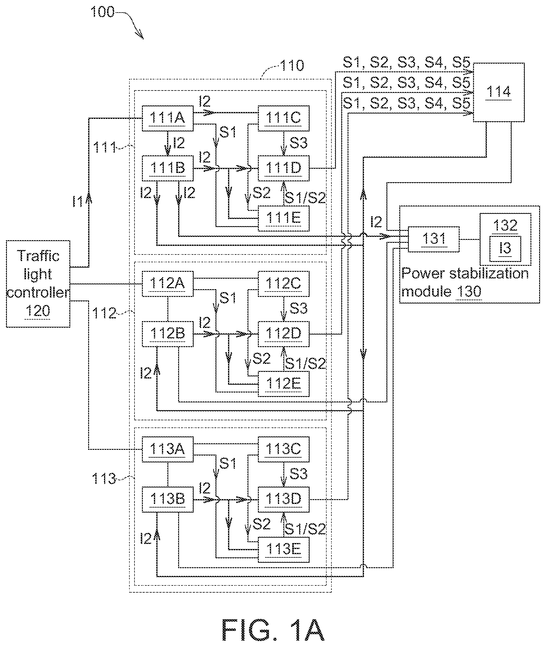
Referring to A to 1 E , A shows a schematic diagram of a traffic light controller 120 of a traffic signal system 100 supplying power to a light-emitting device 111 according to an embodiment of the present invention, B shows a schematic diagram of the traffic light controller 120 of A supplying power to a light-emitting device 112 , C shows a schematic diagram of the traffic light controller 120 of A supplying power to a light-emitting device 113 , D shows a schematic diagram of a power stabilization module 130 of A supplying power to the light-emitting devices 111 to 113 , and E shows a timing diagram of the traffic light controller 120 of A controlling a traffic signal lamp 110 .
As shown in A to 1 C , the traffic signal system 100 includes a traffic signal lamp 110 , a traffic light controller 120 and a power stabilization module 130 . The traffic signal lamp 110 includes a plurality of light-emitting devices 111 to 113 and a wireless communication module 114 . Each of the light-emitting devices 111 to 113 includes a light-emitting element, a power distribution module, a power module, a controller and a measuring element. In each light-emitting device, the power module is configured to convert an alternating current I 1 (for example, supply mains) into a direct current I 2 and supply the direct current I 2 to the light-emitting element and the power distribution module. The controller is electrically coupled to the power distribution module. The measuring element is electrically coupled to the power distribution module and the power module. When a selected-one of the light-emitting devices receive the alternating current I 1 , the power distribution modules of the selected-one supplies the direct current I 2 to the controller and the measuring element of the selected-one and the power distribution modules of the others of the light-emitting devices. As a result, as long as any one of the light-emitting devices 111 to 113 receives the alternating current I 1 (is powered), the controllers and measuring element of the others light-emitting devices could be powered to normally operate.
Taking the light-emitting device 111 as an example, as shown in A , the light-emitting device 111 includes a power module 111 A, a power distribution module 111 B, a light-emitting element 111 C, a controller 111 D and a measuring element 111 E. When the light-emitting device 111 (the selected-one) receives the alternating current I 1 (corresponding to a driving interval T 111 in E ), the power module 111 A could convert the alternating current I 1 into the direct current I 2 and supply the direct current I 2 to the light-emitting element 111 C and the power distribution module 111 B. The controller 111 D is electrically coupled to the power distribution module 111 B and the measuring element 111 E. The measuring element 111 E is electrically coupled to the power distribution module 111 B and the power module 111 A. When the light-emitting device 111 (the selected-one) receives the alternating current I 1 , the power distribution module 111 B of the light-emitting device 111 supplies the direct current I 2 to the controller 111 D and the measuring element 111 E and the power distribution modules 112 B and 113 B of the other light-emitting devices 112 and 113 . As a result, as long as the light-emitting device 111 is powered, the controllers 112 D to 113 D and the measuring elements 112 E to 113 E of the other light-emitting devices 112 to 113 could be powered to operate normally.
The measuring element 111 E could measure the driving information S 1 and S 2 . The driving information S 1 includes, for example, current data of the alternating current I 1 received by the power module 111 A, and the driving information S 2 includes, for example, voltage data and/or current data of the direct current I 2 that drives the light-emitting element 111 C.
As shown in B , the light-emitting device 112 includes a power module 112 A, a power distribution module 112 B, a light-emitting element 112 C, a controller 112 D and a measuring element 112 E. After the light-emitting device 112 receives the alternating current I 1 (corresponding to a driving interval T 112 in E ), the flow of the alternating current I 1 through the light-emitting device 112 is similar to that of the light-emitting device 111 described above, and it will not be repeated here. As a result, as long as the light-emitting device 112 is powered, the controllers 111 D, 113 D and the measuring elements 111 E, 113 E of the other light-emitting devices 111 and 113 could be powered to operate normally. Similarly, the measuring element 112 E could measure the driving information S 1 and S 2 . The driving information S 2 includes, for example, current data of the alternating current I 1 received by the power module 112 A, and the driving information S 2 includes, for example, voltage data and/or current data of the direct current I 2 that drives the light-emitting element 112 C.
As shown in C , the light-emitting device 113 includes a power module 113 A, a power distribution module 113 B, a light-emitting element 113 C, a controller 113 D and a measuring element 113 E. After the light-emitting device 113 (the selected-one) receives the alternating current I 1 (corresponding to a driving interval T 113 in E ), the flow of the alternating current I 1 through the light-emitting device 113 is similar to that of the light-emitting device 111 described above, and it will not be repeated here. As a result, as long as the light-emitting device 113 is powered, the controllers 111 D, 112 D and the measuring elements 111 E, 112 E of the other light-emitting devices 111 and 112 could be powered to operate normally. Similarly, the measuring element 113 E could measure the driving information S 1 and S 2 . The driving information S 2 includes, for example, current data of the alternating current I 1 received by the power module 113 A, and the driving information S 2 includes, for example, voltage data and/or current data of the direct current I 2 that drives the light-emitting element 113 C.
The aforementioned controller is, for example, a physical circuit formed by at least one semiconductor manufacturing process. The aforementioned measuring element is, for example, a sensor, which could obtain or detect driving information S 1 and S 2 .
In an embodiment, the light-emitting elements of each light-emitting device could emit different colors of light. For example, the light-emitting element 111 C of the light-emitting device 111 could emit one of red light, orange light and green light, the light-emitting element 112 C of the light-emitting device 112 could emit another of red light, orange light and green light, and the light-emitting element 113 C could emit the other of red light, orange light and green light. In addition, the embodiment of the present invention does not limit the number of light-emitting devices, and it could be less than 3 or more than 3. In another embodiment, the color of light emitted by the light-emitting element could be light other than red light, orange light and green light.
As shown in A , in each light-emitting device, the light-emitting element is electrically coupled to the controller for transmitting the luminance information of the light-emitting element to the controller.
Taking the light-emitting device 111 as an example, as shown in A , the light-emitting element 111 C is electrically coupled to the controller 111 D, and could transmit the luminance information S 3 of the light-emitting element 111 C to the controller 111 D. Taking the light-emitting device 112 as an example, as shown in B , the light-emitting element 112 C is electrically coupled to the controller 112 D, and could transmit the luminance information S 3 of the light-emitting element 112 C to the controller 112 D. Taking the light-emitting device 113 as an example, as shown in C , the light-emitting element 113 C is electrically coupled to the controller 113 D, and could transmit the light emitting brightness information S 3 of the light-emitting element 113 C to the controller 113 D.
The controller could transmit the received information to the wireless communication module 114 . Taking the light-emitting device 111 as an example, as shown in A , the controller 111 D could transmit the information to the wireless communication module 114 after receiving the driving information S 1 , S 2 and the luminance information S 3 of the light-emitting device 111 . Taking the light-emitting device 112 as an example, as shown in B , the controller 112 D could transmit the information to the wireless communication module 114 after receiving the driving information S 1 , S 2 and the luminance information S 3 of the light-emitting device 112 . Taking the light-emitting device 113 as an example, as shown in C , the controller 113 D could transmit the information to the wireless communication module 114 after receiving the driving information S 1 , S 2 and the luminance information S 3 of the light-emitting device 113 .
In each light-emitting device, the controller is configured to: receive the driving information detected by the corresponding measuring element; obtain a difference between the driving information and a driving default value; determine whether the difference exceeds a driving allowable range; and when the difference exceeds the driving allowable range, generate an abnormal signal. The aforementioned driving default values could be pre-stored in the controller. Alternatively, the driving default values could be stored in a memory and the controller could access the driving default values of the memory. The embodiment of the present invention does not limit the driving default value. The driving allowable range is, for example, a ratio of the driving default value, and the ratio is, for example, a real number ranging between 1% and 10%.
Taking the light-emitting device 111 as an example, as shown in A , the controller 111 D of the light-emitting device 111 is configured to: receive the driving information (S 1 and/or S 2 ) detected by the measuring element 111 E; obtain the difference between the driving information (S 1 and/or S 2 ) and the driving default value; determine whether the difference exceeds the driving allowable range; and when the difference exceeds the driving allowable range, generate a driving abnormal signal S 4 . When the difference does not exceed the driving allowable range, the controller 111 D could not generate the driving abnormal signal S 4 . In another embodiment, the controller 111 D could transmit the driving information (S 1 and/or S 2 ) to the wireless communication module 114 regardless of whether the difference exceeds the driving allowable range. As shown in B , the controller 112 D of the light-emitting device 112 could perform the same or similar actions, and it will not be repeated here. As shown in C , the controller 113 D of the light-emitting device 113 could perform the same or similar actions, and it will not be repeated here.
In each light-emitting device, the controller is further configured to: receive a luminance information of the corresponding light-emitting element; obtain a difference between the luminance information and a luminance preset value; determine whether the difference exceeds a luminance allowable range; and when the difference exceeds the luminance allowable range, generate a luminance abnormal signal. The above luminance preset value could be pre-stored in the controller; alternatively, the luminance preset value could be stored in a memory, and the controller could access the luminance preset value in the memory. The embodiments of the present invention do not limit the luminance preset value. The luminance allowable range is, for example, a ratio of the luminance preset value, wherein the ratio is, for example, a real number ranging between 1% and 10%.
Taking the light-emitting device 111 as an example, as shown in A , the controller 111 D of the light-emitting device 111 is further configured to: receive the luminance information S 3 of the light-emitting element 111 C; obtain the difference between the luminance information S 3 and the luminance preset value; determine whether the difference exceeds the luminance allowable range; and when the difference exceeds the luminance allowable range, generate the luminance abnormal signal S 5 . When the difference does not exceed the luminance allowable range, the controller 111 D could not generate the luminance abnormal signal S 5 . The controller 111 D could transmit the luminance abnormal signal S 5 to the wireless communication module 114 . In another embodiment, the controller 111 D could transmit the luminance information S 3 to the wireless communication module 114 regardless of whether the difference exceeds the luminance allowable range. As shown in B , the controller 112 D of the light-emitting device 112 could perform the same or similar actions, and it will not be repeated here. As shown in C , the controller 113 D of the light-emitting device 113 could perform the same or similar actions, and it will not be repeated here.
In addition to the above-mentioned information, the controller of each light-emitting device could also obtain, from the measuring element, the light-emitting element, the driving information S 1 and S 2 and/or the luminance information S 3 , information such as the light-emitting time of the light-emitting elements, damaged quantity of the of the light-emitting elements and/or damaged ratio of the of the light-emitting elements, and transmit such information to the wireless communication module 114 .
As described above, as long as the selected-one of the light-emitting devices is powered, the controllers and measuring elements of the other light-emitting devices could be powered. Thus, in the driving interval of the selected-one (is powered) of the light-emitting devices, the controller and measuring element of each light-emitting device could normally and constantly obtain the information of the light-emitting element and the power module.
As shown in A to 1 C , the wireless communication module 114 could, by using wireless communication technology, communicate with a management platform or an external electronic device (not shown), such as a server, a computer or a smart phone, etc. The wireless communication module 114 could transmit the received signals of each light-emitting device (for example, the driving information S 1 and S 2 , the luminance information S 3 , the driving abnormal signal S 4 and/or the luminance abnormal signal S 5 ) to the management platform and/or the external electronic device. The operator could monitor the actual status of the traffic signal lamp 110 through the management platform or an external electronic device.
As shown in A to 1 C , in each light-emitting device, when the light-emitting device (the selected-one) receives the alternating current I 1 (corresponding to the driving interval T 113 of E ), the power module could supply the direct current I 2 to the wireless communication module 114 for the normal operation of the wireless communication module 114 . For example, the signal (for example, the driving information S 1 and S 2 , the luminance information S 3 , the driving abnormal signal S 4 and/or the luminance abnormal signal S 5 ) received by each light-emitting device is transmitted to the management platform or an external electronic device.
As shown in E , the traffic light controller 120 could output a driving signal D, so that the light-emitting elements of each light-emitting device of the traffic signal lamp 110 are enabled to emit light in the corresponding driving interval (the driving interval of the selected-one) (it does not emit light in the non-corresponding driving interval). C only shows one driving period T, but the driving signal D could have multiple continuous driving periods T or multiple driving periods T with different time lengths. In one driving cycle T of the driving signal D, the driving interval T 111 represents the driving time of the traffic light controller 120 for the light-emitting device 111 , the driving interval T 112 represents the driving time of the traffic light controller 120 for the light-emitting device 112 , and the driving interval T 113 represents the driving time of the traffic light controller 120 for the light-emitting device 113 . in addition, although not shown, there is a short power supply interval T s between two adjacent driving intervals, and in the power supply interval T s , the light-emitting device is not powered. However, in the power supply interval T s , the power stabilization module 130 could supply power to each light-emitting device to maintain its normal operation. Further examples are described below.
As shown in A to 1 C , the power distribution module of each light-emitting device is electrically coupled to the power stabilization module 130 . For example, the power distribution module 111 B of the light-emitting device 111 , the power distribution module 112 B of the light-emitting device 112 and the power distribution module 113 B of the light-emitting device 113 are electrically coupled to the power stabilization module 130 . The power distribution module could supply the direct current I 2 to the power stabilization module 130 for being stored. For example, when the traffic light controller 120 supplies the alternating current I 1 to the light-emitting device 111 (as shown in A ), the power distribution module 111 B of the light-emitting device 111 could supply the direct current I 2 to the power stabilization module 130 for being stored. When the traffic light controller 120 supplies the alternating current I 1 to the light-emitting device 112 (as shown in B ), the power distribution module 112 B of the light-emitting device 112 could supply the direct current I 2 to the power stabilization module 130 for being stored. When the traffic light controller 120 supplies the alternating current I 1 to the light-emitting device 113 (as shown in C ), the power distribution module 113 B of the light-emitting device 113 could supply the direct current I 2 to the power stabilization module 130 for being stored.
As shown in A to 1 C , the power stabilization module 130 includes a power output unit 131 and a power storage unit 132 . The power output unit 131 is electrically coupled to the power storage unit 132 . The power output unit 131 could supply the direct current I 2 to the power storage unit 132 for being stored (storage current I 3 ). The power output unit 131 is a physical circuit formed by, for example, at least one semiconductor manufacturing process, and the power storage unit 132 is, for example, a battery.
As shown in D , when all light-emitting devices 111 to 113 do not receive the alternating current I 1 (for example, in the power supply interval T s of E ), the power supply stabilization module 130 could supply the storage current I 3 (for example, direct current) to the power distribution modules 111 B to 113 B of all light-emitting devices 111 to 113 . As a result, even if all light-emitting devices 111 to 113 are not driven by the alternating current I 1 within the power supply interval T s , the power stabilization module 130 is still powered to operate normally.
As shown in D , after the power distribution modules 111 B to 113 B receive the storage current I 3 , the power distribution modules 111 B to 113 B could supply power to the controller, measuring element and wireless communication module by using the methods described for A to 1 C . Taking the light-emitting device 111 as an example, as shown in A , after the power distribution module 111 B receives the storage current I 3 , the power distribution module 111 B could supply the storage current I 3 to the controller 111 D and the measuring element 111 E, and the controller 111 D and measuring element 111 E could perform the same actions as described for A . Taking the light-emitting device 112 as an example, as shown in B , after the power distribution module 112 B receives the storage current I 3 , the power distribution module 112 B could supply the storage current I 3 to the controller 112 D and the measuring element 112 E, and the controller 112 D and measuring element 112 E could perform the same actions as described for A . Taking the light-emitting device 113 as an example, as shown in C , after the power distribution module 113 B receives the storage current I 3 , the power distribution module 113 B could supply the storage current I 3 to the controller 113 D and the measuring element 113 E, and the controller 113 D and measuring element 113 E could perform the same actions as described for A .
As shown in D , when all light-emitting devices 111 to 113 do not receive the alternating current I 1 (for example, in the power supply interval T s of E ), the power supply stabilization module 130 could supply the storage current I 3 (for example, the direct current) to the wireless communication module 114 for the normal operation of the wireless communication module 114 . For example, the received signal (for example, the driving information S 1 and S 2 , the luminance information S 3 , the driving abnormal signal S 4 and/or the luminance abnormal signal S 5 ) of each light-emitting device is transmitted to the management platform or an external electronic device. As a result, even if all light-emitting devices 111 to 113 are not driven by the alternating current I 1 within the power supply interval T s , the power stabilization module 130 still supplies power to the wireless communication module 114 so that the wireless communication module 114 could operate normally.
To sum up, no matter whether the traffic signal lamp 110 is driven by the alternating current I 1 or not, the measuring element and the controller of each light-emitting device of the traffic signal lamp 110 could constantly be in the powered state. In addition, when the selected-one of the light-emitting devices of the traffic signal lamp 110 is driven by the alternating current I 1 , the selected-one supplies power to its own controller and the measuring element as well as the controller and the measuring element of other light-emitting devices. When the traffic signal lamp 110 is not driven by the alternating current I 1 , the power supply stabilization module 130 supplies power to the controller and the measuring element of each light-emitting device.
Furthermore, it takes a period of time for the measuring element and the controller to start from the unpowered state to the normal operation state, and such period of time causes a detection empty-window period. Since the measuring element and the controller of each light-emitting device in the embodiments of the present invention could be constantly powered, they could constantly be in the normal operation state, and accordingly it could avoid the detection empty-window period. In addition, conventional measuring element and controller need enough power to be the normal operation state from the unpowered state, and thus the controller can't operate if the power supply time is very short (for example, the driving interval T 112 in E ). However, since the measuring element and the controller of the embodiment of the present invention could constantly be in the powered state, it is not required to consider whether the time required for enabling is sufficient.
Referring to A to 2 C , A shows a schematic diagram of a traffic light controller 120 of a traffic signal system 200 supplying power to a light-emitting device 211 according to another embodiment of the present invention, B shows a schematic diagram of the traffic light controller 120 of A supplying power to the light-emitting device 212 , and C shows a schematic diagram of the traffic light controller 120 of A supplying power to the light-emitting device 213 . The traffic signal system 200 includes the traffic signal lamp 210 , the traffic light controller 120 and the power stabilization module 130 . The traffic signal lamp 210 includes a plurality of the light-emitting devices 211 to 213 , the wireless communication module 114 and a power distribution module 215 . The power distribution module 215 is, for example, a physical circuit formed by at least one semiconductor manufacturing process.
It is different from the aforementioned traffic signal system 100 , the controller and the measuring element of each light-emitting device in the traffic signal system 200 of the embodiment of the present invention are uniformly powered by the power supply stabilization module 130 , and it will be further described below.
As shown in A to 2 C , the light-emitting devices 211 to 213 each includes the light-emitting element, the power module, the controller, and the measuring element, wherein the power module could convert the alternating current I 1 into a first direct current I 21 and transmit the first direct current I 21 to the light-emitting element, and the measuring element is electrically coupled to the light-emitting element and the power module. The power distribution module 215 is configured to convert the alternating current I 1 into a second direct current I 22 and transmit the second direct current I 22 to the power stabilization module 130 . The power distribution module 130 is configured to store the second direct current I 22 as the storage current I 3 , and supply the storage current I 3 to the controller and the measuring element of each light-emitting device. As a result, the controller and the measuring element of each light-emitting device could constantly receive the power supplied by the power stabilization module 130 , and thus could operate normally.
Taking the light-emitting device 211 as an example, as shown in A , the light-emitting device 211 includes the power module 111 A, the light-emitting element 111 C, the controller 111 D and the measuring element 111 E. The power module 111 A could convert the alternating current I 1 into the first direct current I 21 and supply the first direct current I 21 to the light-emitting element 111 C. The measuring element 111 E is electrically coupled to the power module 111 A and the light-emitting element 111 C. The power distribution module 215 is configured to convert the alternating current I 1 into the second direct current I 22 and supply the second direct current I 22 to the power stabilization module 130 . The power stabilization module 130 is configured to store the second direct current I 22 as the storage current I 3 , and supply the storage current I 3 to the controllers 111 D to 113 D and the measuring elements 111 E to 113 E of the light-emitting devices 211 to 213 . As a result, the controllers 111 D to 113 D and the measuring elements 111 E to 113 E of the light-emitting devices 111 to 113 could constantly receive power supplied by the power stabilization module 130 , and could operate constantly and normally.
Taking the light-emitting device 212 as an example, as shown in B , the light-emitting device 212 includes the power module 112 A, the light-emitting element 112 C, the controller 112 D and the measuring element 112 E. The measuring element 112 E is electrically coupled to the power module 112 A and the light-emitting element 112 C. The power module 112 A, the measuring element 112 E, and the light-emitting element 112 C could perform similar or identical actions, and it will not be repeated here. As a result, the controllers 111 D to 113 D and the measuring elements 111 E to 113 E of the light-emitting devices 211 to 213 could constantly receive power supplied by the power stabilization module 130 , and could operate constantly and normally.
Taking the light-emitting device 213 as an example, as shown in C , the light-emitting device 213 includes the power module 113 A, the light-emitting element 113 C, the controller 113 D and the measuring element 113 E. The measuring element 113 E is electrically coupled to the power module 113 A and the light-emitting element 113 C. The power module 113 A, the measuring element 113 E, and the light-emitting element 113 C could perform similar or identical actions, and it will not be repeated here. As a result, the controllers 111 D to 113 D and the measuring elements 111 E to 113 E of the light-emitting devices 211 to 213 could constantly receive power supplied by the power stabilization module 130 , and could operate constantly and normally.
In the present embodiment, the power distribution module 215 could convert the alternating current I 1 into the second direct current I 22 . However, in another embodiment, the power distribution module 215 could not have the function of converting AC to DC; correspondingly, the traffic signal system 200 further includes a power module (not shown) connecting the power distribution module 215 with the traffic light controller 120 for converting the alternating current I 1 supplied by the traffic light controller 120 into the second direct current I 22 and supply the second direct current I 22 to the power stabilization module 130 .
In addition, the power stabilization module 130 could supply the storage current I 3 to the wireless communication module 114 , in addition to uniformly supplying power to the controller and the measuring element of each light-emitting device of the traffic signal system 200 .
Referring to , shows a flow chart of the lamp-state detection method of the traffic signal lamp of the traffic signal system 100 in A to 1 D .
In step S 110 , when the selected-one of the light-emitting devices 111 to 113 receives the alternating current I 1 , the power module of the selected-one converts the alternating current I 1 into the direct current I 2 .
In step S 120 , the power module of the selected-one supplies the direct current I 2 to the light-emitting element and the power distribution module of the selected-one.
In step S 130 , the power distribution module of the selected-one supplies the direct current I 2 to the controller and the measuring element of the selected-one and the power distribution modules of the others of the light-emitting devices 111 to 113 .
Other embodiments of the lamp-state detection method of the traffic signal lamp of the traffic signal system 100 according to the embodiment of the present invention have been described above, and it will not be repeated here.
Referring to , shows a flow chart of the lamp-state detection method of the traffic signal lamp of the traffic signal system 200 in A to 2 C .
In step S 210 , when the selected-one of the light-emitting devices 211 to 213 receives the alternating current I 1 , the power module of the selected-one converts the alternating current I 1 into the first direct current I 21 .
In step S 220 , the power module of the selected-one supplies the first direct current I 21 to the light-emitting element of the selected-one.
In step S 230 , the power distribution module 215 converts the alternating current I 1 into the second direct current I 22 .
In step S 240 , the power distribution module 215 supplies the second direct current I 22 to the power stabilization module 130 .
In step S 250 , the power distribution module 130 stores the second direct current I 22 as the storage current I 3 .
In step S 260 , the power stabilization module 130 supplies the storage current I 3 to the controller and measuring element of each light-emitting device. Furthermore, the power stabilization module 130 supplies the storage current I 3 to the controllers 111 D to 113 D and measuring elements 111 E to 113 E of the light-emitting devices 211 to 213 .
Other embodiments of the lamp-state detection method of the traffic signal lamp of the traffic signal system 200 according to the embodiment of the present invention have been described above, and it will not be repeated here.
To sum up, the embodiment of the present invention proposes a traffic signal lamp, a traffic signal system and a lamp-state detection method using the same, the controller and/or the measurement of each light-emitting device of the traffic signal lamp could be constantly powered and could operate normally, regardless of whether the enabling time is sufficient. In an embodiment, when the selected-one of the light-emitting devices receive the alternating current, the selected-one supplies power to the controllers and/or the measuring elements of all light-emitting devices, and charge the power stabilization module at the same time. When all light-emitting devices do not receive the alternating current, the power stabilization module supplies power (the storage current) to the controllers and/or the measuring elements of all light-emitting devices. In another embodiment, when the selected-one of the light-emitting devices receive the alternating current, the selected-one charge the power distribution module, and the power distribution module uniformly supplies power (the storage current) to the controllers and/or the measuring element of all light-emitting devices. As a result, all light-emitting devices could be constantly powered, so that their components (for example, the measuring element and/or the controller, etc.) could operate constantly normally.
While the invention has been described by way of example and in terms of the preferred embodiment (s), it is to be understood that the invention is not limited thereto. Based on the technical features embodiments of the present invention, a person ordinarily skilled in the art will be able to make various modifications and similar arrangements and procedures without breaching the spirit and scope of protection of the invention. Therefore, the scope of protection of the present invention should be accorded with what is defined in the appended claims.
Figures (9)
Citations
This patent cites (1)
- USWO-2011/030920